jurandir primo, p - perse - publique-se - publicar seu ... · o objetivo deste livro é descrever...
TRANSCRIPT
Jurandir Primo, P.E

Welding Technology and Inspection Procedures-AWS D1.1
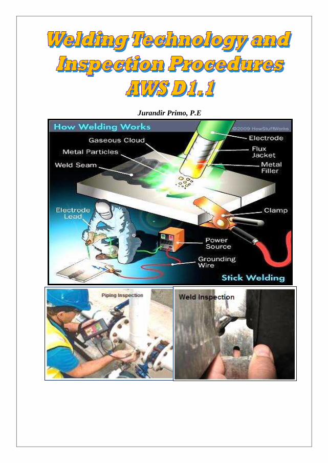
Welding Technology and Inspection Procedures –AWS D1.1
Jurandir Primo
Copyright @ 2012
1ª edição – junho de 2012
Capa:
Jurandir Primo – Sorocaba/SP
Primo, Jurandir
Welding Technology and Inspection Procedures –AWS D1.1
Índice para pesquisas: Soldagem.
ISBN:
Livro no sistema de auto publicação cuja edição, revisão, diagramação e capa foram
selecionadas pelo próprio autor, para não encarecer a obra e facilitar a compra, a
todos os estudantes e interessados em assuntos técnicos e engenharia de
equipamentos.
Portanto, qualquer pessoa pode ter esse livro, sem necessidade de copiar, digitalizar
ou utilizar outros processos de reprodução, porque foi executado para custar menos
que o valor de uma pizza.
No entanto, o autor permite que todas as partes do livro possam ser copiadas ou
reproduzidas para fundamentos educacionais, instrutivos e treinamento técnico.
Para adquirir esta ou outras publicações do autor, enviar solicitação para:

Jurandir Primo
©2011 Jurandir Primo Page 3
of 167
PREFÁCIO:
O objetivo deste livro é descrever de forma didática e resumida os diversos
processos de soldagem e o métodos para inspeção conforme AWS D1. 1,
cujos tópicos poderão servir de pesquisa a estudantes e interessados em
conhecer as origens e fundamentos da tecnologia e engenharia.
Devido as facilidades atuais de comunicação existentes, os futuros técnicos
e engenheiros poderão, com certeza, ser melhores que as gerações
passadas, no entanto, mais que tudo, deverão ser respeitadas pelo esforço
de contribuir para as novas realidades.
O autor compreende perfeitamente ente, que não é um escritor especialista
e está aberto a críticas construtivas e sugestões para melhoria desse livro.
Esse livro serve para todos que, assim como eu, vieram das pequenas para
as grandes cidades, para estudar, trabalhar, enfrentar todos os tipos de
dificuldades e mesmo sem o preparo dos modernos programas de
computador, ainda hoje, procuram contribuir para as necessidades de
instrução e educação para todos os níveis sociais, que devem ser os valores
verdadeiros de democracia, evolução e progresso em qualquer país.
Welding Technology and Inspection Procedures-AWS D1.1
Esse livro é parte de uma série de publicações para as diversas áreas de
Engenharia:
ASME – Vasos de Pressão;
Automação & Sistemas;
Bombas Centrífugas;
Cabeamento & Fibras Óticas;
Compressores de Ar;
END - Ensaios não Destrutivos;
Fibras Ópticas;
Gerenciamento de Projetos;
Hidráulica;
HVAC – Ar Condicionado;
Instrumentação;
Óleo & Gás – Perfuração e Produção
Pavimentação Asfáltica;
Pintura Industrial;
Pneumática;
PLC & Controle de Sistemas Fieldbus;
Selos Mecânicos;
Tecnologia de Soldagem;
Testes, Inspeção & Comissionamento;
Torres de Resfriamento;
Transportadores de Correia e Corrente;
Trocadores de Calor;
Tubulação Industrial;
Válvulas Industriais;
Ventilação Industrial;
Outros...

Jurandir Primo
©2011 Jurandir Primo Page 5
of 167
Contents:
I. INTRODUCTION
II. MAIN WELD JOINT TYPES
III. JOINT DESIGN AND WELD PREPARATION
IV. STANDARDS FOR WELDING POSITIONS
V. WELDING SYMBOLS
VI. WELDING PROCESSES
VII. WELDING OF STEELS
VIII. WELDING FOR JOISTS AND MACHINING RAILS
IX. BOILERMAKER
X. WELDING OF RAILS, CAST AND WROUGHT STEELS
XI. NONDESTRUCTIVE TESTING
XII. WELDING INSPECTION PROCEDURES
XIII. WELDING FAILURES
XIV. WELDING TEST COUPON PROCEDURES
XV. WELDING ELECTRODES AND PREHEAT REQUIREMENTS
XVI. CLASSIFICATION OF ELECTRODES
XVII. MECHANICAL PROPERTIES
XVIII. DESTRUCTIVE TESTING
XIX. INSPECTION OF WELD PROFILES
XX. LEAK TESTS
XXI. HYDROSTATIC AND PNEUMATIC TESTS
XXII. LEVELS OF CERTIFICATION
XXIII. WELDING INSPECTOR KNOWLEDGES
XXIV. WELDING PROCEDURE SPECIFICATION
XXV. WELDING EQUIPMENT
XXVI. SAFETY PRECAUTIONS
XXVII. CODES AND STANDARDS
XXVIII. NONDESTRUCTIVE EXAMINATIONS ASME SECTION-V
XXIX. ASME B31.3 & API-570 NONDESTRUCTIVE TESTING
XXX. REFERENCES

Welding Technology and Inspection Procedures-AWS D1.1
To :
All teachers of my childhood , since my first letters ,
elementary, high school and college ;
All who, with absolute sincerity, fights for social justice
and life environment;
Everyone that has gone, but came to this planet as
missionaries of Education.

Jurandir Primo
©2011 Jurandir Primo Page 7
of 167
I - INTRODUCTION
This book is short and very practical for students, welders, technicians, welding
inspectors and engineers the way anyone can research some subject in a timely manner
to carry a work without wasting too much his precious time.
It covers the main manufacturing welding processes, materials and inspection
procedures according to AWS D1.1 and ASME Section IX, commonly used for field
construction projects:
The main welding processes are:
SMAW (shielded metal arc), GMAW (gas metal arc), GTAW (gas tungsten arc),
FCAW (flux-cored arc), SAW (submerged arc), CAW (carbon arc) PAW (plasma
arc) and EGW (electrogas welding).
Metallurgy is not the scope and is limited in selecting welding processes, materials,
and inspection procedures for the common construction applications.
II – MAIN WELD JOINT TYPES
The five main types of joints for welding are the butt joint, lap joint, corner joint, T
joint, and edge joint. Each of these joints can be welded in different ways and with a
variety of welding processes.
1. Square-Groove Welds
The square-groove weld on one side of the joint is generally limited to thin sheet-metal
sections. The maximum (max) thickness for these welds is 1/16 in. (1.6 mm). Shown
here, left to right, are a butt joint, a corner joint, and an edge-flange type of edge
joint.
A backing strip is sometimes used on the opposite side of a square-groove weld. The
backing strip keeps the molten weld metal from falling through and permits the use of
more heat which results in better fusion. The welder can make a strong square-groove
weld that completely penetrates the joint.
Welding Technology and Inspection Procedures-AWS D1.1
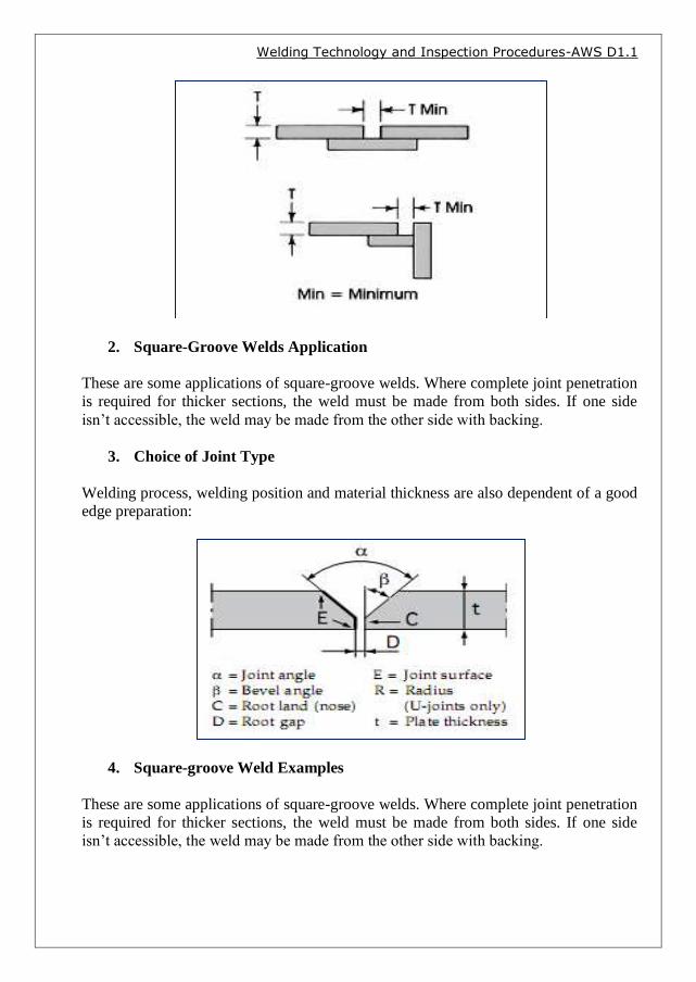
2. Square-Groove Welds Application
These are some applications of square-groove welds. Where complete joint penetration
is required for thicker sections, the weld must be made from both sides. If one side
isn’t accessible, the weld may be made from the other side with backing.
3. Choice of Joint Type
Welding process, welding position and material thickness are also dependent of a good
edge preparation:
4. Square-groove Weld Examples
These are some applications of square-groove welds. Where complete joint penetration
is required for thicker sections, the weld must be made from both sides. If one side
isn’t accessible, the weld may be made from the other side with backing.

Jurandir Primo
©2011 Jurandir Primo Page 9
of 167
5. Single-V Joints
Joints for single-V-groove welds are prepared as shown below. Generally, the
included angle of the V is about 60 °. For horizontal welding, the joint is modified to
help keep the molten weld metal from running out of the groove.
Welding Technology and Inspection Procedures-AWS D1.1
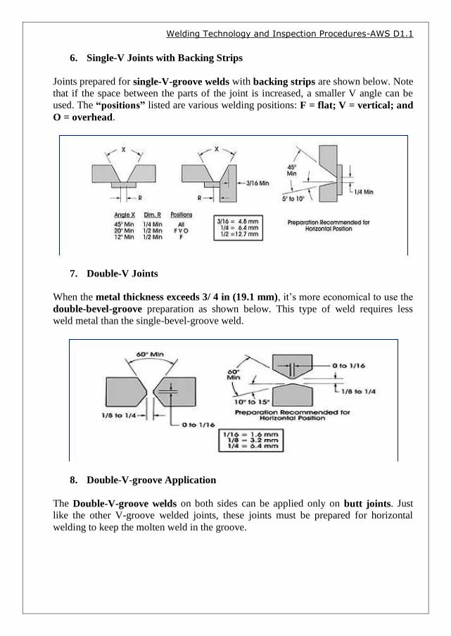
6. Single-V Joints with Backing Strips
Joints prepared for single-V-groove welds with backing strips are shown below. Note
that if the space between the parts of the joint is increased, a smaller V angle can be
used. The “positions” listed are various welding positions: F = flat; V = vertical; and
O = overhead.
7. Double-V Joints
When the metal thickness exceeds 3/ 4 in (19.1 mm), it’s more economical to use the
double-bevel-groove preparation as shown below. This type of weld requires less
weld metal than the single-bevel-groove weld.
8. Double-V-groove Application
The Double-V-groove welds on both sides can be applied only on butt joints. Just
like the other V-groove welded joints, these joints must be prepared for horizontal
welding to keep the molten weld in the groove.

Jurandir Primo
©2011 Jurandir Primo Page 11
of 167
9. V-groove Weld Penetration
The V-groove weld is used on relatively thick metals and becomes difficult to obtain
complete joint penetration by welding in only one side. Then, either welding from both
sides or welding with a backing strip is usually necessary for thorough penetration.

Welding Technology and Inspection Procedures-AWS D1.1
10. Single-Bevel-Groove
Joints for single-bevel-groove welds on one or both sides are easier and more
economical to prepare than joints with V-groove welds. Only one of the joint edges has
to be beveled in preparation for the weld.
11. Single-Bevel-Groove with Backing Strips
When applying the single-bevel-groove welds on one side, use a backing strip to
help achieve complete joint penetration. Note the three different methods of
preparing corner joints.
12. Single-Bevel-Groove Weld Penetration
Bevel-groove welds with partial and complete joint penetration are below. Welds can
be made from one or both sides, because it’s difficult to ensure complete joint
penetration from one side only. Consequently, to obtain complete penetration and
maximum strength, backing strips must be used.
Jurandir Primo
©2011 Jurandir Primo Page 13
of 167
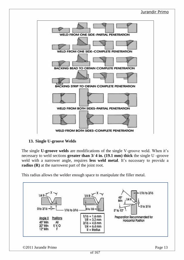
13. Single U-groove Welds
The single U-groove welds are modifications of the single V-groove weld. When it’s
necessary to weld sections greater than 3/ 4 in. (19.1 mm) thick the single U -groove
weld with a narrower angle, requires less weld metal. It’s necessary to provide a
radius (R) at the narrowest part of the joint root.
This radius allows the welder enough space to manipulate the filler metal.

Welding Technology and Inspection Procedures-AWS D1.1
14. Double U-groove Welds
The joints shown below are prepared for double-U-groove welds. This weld is used on
metal thicknesses exceeding 11⁄2 in. (38.1 mm). Preparation of the edges is the same
as for the single U-groove weld except that the grooves are prepared on both sides of
the plate edges.
15. Single J-groove Welds
The J-groove is similar in shape to the U-groove but half of its dimension. Just like
the single-U-groove weld, the single-J-groove weld is used with metal thicknesses
above 3⁄4 in (19.1 mm).
16. Double J-groove Welds
The Double-J-groove welds on both sides have the same basic applications as the
double-bevel groove welds. The J-groove welds are used on thicknesses greater than
1 ½ in. (38.1 mm).

Jurandir Primo
©2011 Jurandir Primo Page 15
of 167
17. U-groove and J-groove Welds Application
The U-groove welds are designed to save filler metal when thick sections are welded
greater than 3/ 4 in. (19.1 mm) thick. Shown here are typical examples of welded U-
grooved butt and corner joints.
18. Groove Design According to Metal Thickness