conexÃo
TRANSCRIPT
The aim of this feature is to share up-dates, design tips and answers to queries. The Steel Construction Instituteprovides items which, it is hoped, will prove useful to the industry.
ADVISORY DESK
AD 266 Shear Connection in composite beamsFollowing some recent questions on the requirements given in BS 5950-3: 1990 for the design of the shear connection in compositebeams, a clarification of three major issues is given in this advisory deskarticle. These issues are:
• Effective breadth of the concrete flange (BS 5950-3: 1990 Clause 4.6)• Partial shear connection (BS 5950-3: 1990 Clause 5.5)• Transverse reinforcement (BS 5950-3: 1990 Clause 5.6)
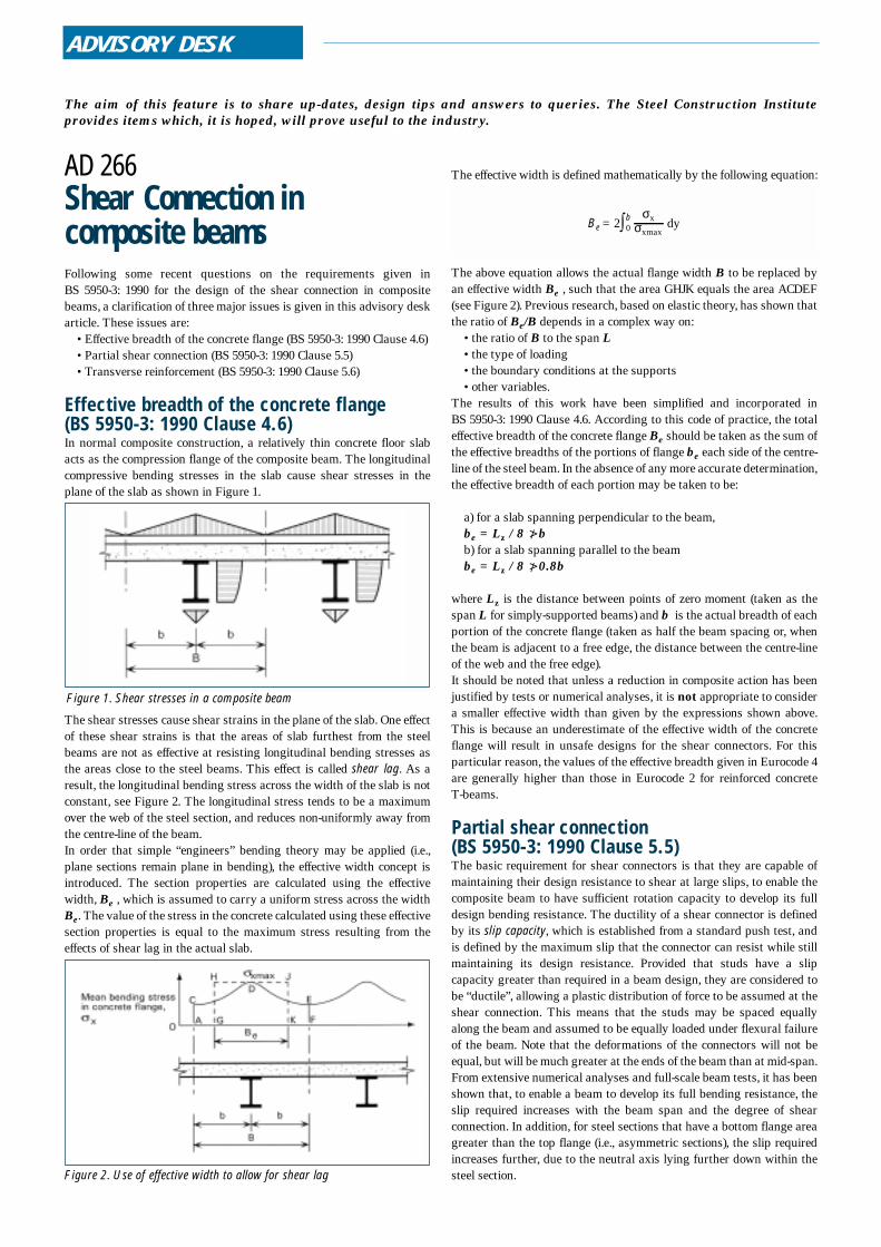
Effective breadth of the concrete flange (BS 5950-3: 1990 Clause 4.6)In normal composite construction, a relatively thin concrete floor slabacts as the compression flange of the composite beam. The longitudinalcompressive bending stresses in the slab cause shear stresses in theplane of the slab as shown in Figure 1.
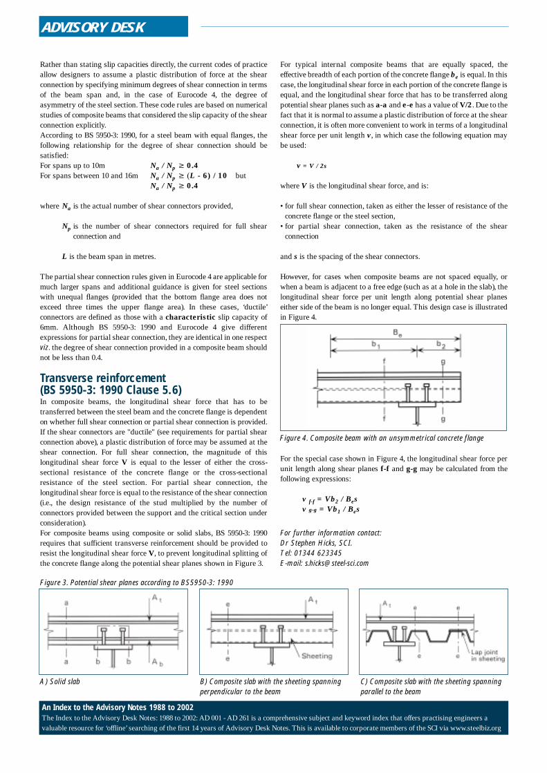
The shear stresses cause shear strains in the plane of the slab. One effectof these shear strains is that the areas of slab furthest from the steelbeams are not as effective at resisting longitudinal bending stresses asthe areas close to the steel beams. This effect is called shear lag. As aresult, the longitudinal bending stress across the width of the slab is notconstant, see Figure 2. The longitudinal stress tends to be a maximumover the web of the steel section, and reduces non-uniformly away fromthe centre-line of the beam. In order that simple “engineers” bending theory may be applied (i.e.,plane sections remain plane in bending), the effective width concept isintroduced. The section properties are calculated using the effectivewidth, Be , which is assumed to carry a uniform stress across the widthBe. The value of the stress in the concrete calculated using these effectivesection properties is equal to the maximum stress resulting from theeffects of shear lag in the actual slab.
The effective width is defined mathematically by the following equation:
The above equation allows the actual flange width B to be replaced byan effective width Be , such that the area GHJK equals the area ACDEF(see Figure 2). Previous research, based on elastic theory, has shown thatthe ratio of Be/B depends in a complex way on:
• the ratio of B to the span L• the type of loading • the boundary conditions at the supports • other variables.
The results of this work have been simplified and incorporated in BS 5950-3: 1990 Clause 4.6. According to this code of practice, the totaleffective breadth of the concrete flange Be should be taken as the sum ofthe effective breadths of the portions of flange be each side of the centre-line of the steel beam. In the absence of any more accurate determination,the effective breadth of each portion may be taken to be:
a) for a slab spanning perpendicular to the beam,be = Lz / 8 >bb) for a slab spanning parallel to the beambe = Lz / 8 >0.8b
where Lz is the distance between points of zero moment (taken as thespan L for simply-supported beams) and b is the actual breadth of eachportion of the concrete flange (taken as half the beam spacing or, whenthe beam is adjacent to a free edge, the distance between the centre-lineof the web and the free edge).It should be noted that unless a reduction in composite action has beenjustified by tests or numerical analyses, it is not appropriate to considera smaller effective width than given by the expressions shown above.This is because an underestimate of the effective width of the concreteflange will result in unsafe designs for the shear connectors. For thisparticular reason, the values of the effective breadth given in Eurocode 4are generally higher than those in Eurocode 2 for reinforced concrete T-beams.
Partial shear connection (BS 5950-3: 1990 Clause 5.5)The basic requirement for shear connectors is that they are capable ofmaintaining their design resistance to shear at large slips, to enable thecomposite beam to have sufficient rotation capacity to develop its fulldesign bending resistance. The ductility of a shear connector is definedby its slip capacity, which is established from a standard push test, andis defined by the maximum slip that the connector can resist while stillmaintaining its design resistance. Provided that studs have a slipcapacity greater than required in a beam design, they are considered tobe “ductile”, allowing a plastic distribution of force to be assumed at theshear connection. This means that the studs may be spaced equallyalong the beam and assumed to be equally loaded under flexural failureof the beam. Note that the deformations of the connectors will not beequal, but will be much greater at the ends of the beam than at mid-span.From extensive numerical analyses and full-scale beam tests, it has beenshown that, to enable a beam to develop its full bending resistance, theslip required increases with the beam span and the degree of shearconnection. In addition, for steel sections that have a bottom flange areagreater than the top flange (i.e., asymmetric sections), the slip requiredincreases further, due to the neutral axis lying further down within thesteel section.
σxmax
σxBe = 2 dyb0
Figure 1. Shear stresses in a composite beam
Figure 2. Use of effective width to allow for shear lag
/
/
ADVISORY DESK
Rather than stating slip capacities directly, the current codes of practiceallow designers to assume a plastic distribution of force at the shearconnection by specifying minimum degrees of shear connection in termsof the beam span and, in the case of Eurocode 4, the degree ofasymmetry of the steel section. These code rules are based on numericalstudies of composite beams that considered the slip capacity of the shearconnection explicitly. According to BS 5950-3: 1990, for a steel beam with equal flanges, thefollowing relationship for the degree of shear connection should besatisfied:For spans up to 10m Na / Np ≥ 0.4For spans between 10 and 16m Na / Np ≥ (L - 6) / 10 but
Na / Np ≥ 0.4
where Na is the actual number of shear connectors provided,
Np is the number of shear connectors required for full shearconnection and
L is the beam span in metres.
The partial shear connection rules given in Eurocode 4 are applicable formuch larger spans and additional guidance is given for steel sectionswith unequal flanges (provided that the bottom flange area does notexceed three times the upper flange area). In these cases, ‘ductile’connectors are defined as those with a characteristic slip capacity of6mm. Although BS 5950-3: 1990 and Eurocode 4 give differentexpressions for partial shear connection, they are identical in one respectviz. the degree of shear connection provided in a composite beam shouldnot be less than 0.4.
Transverse reinforcement (BS 5950-3: 1990 Clause 5.6)In composite beams, the longitudinal shear force that has to betransferred between the steel beam and the concrete flange is dependenton whether full shear connection or partial shear connection is provided.If the shear connectors are "ductile" (see requirements for partial shearconnection above), a plastic distribution of force may be assumed at theshear connection. For full shear connection, the magnitude of thislongitudinal shear force V is equal to the lesser of either the cross-sectional resistance of the concrete flange or the cross-sectionalresistance of the steel section. For partial shear connection, thelongitudinal shear force is equal to the resistance of the shear connection(i.e., the design resistance of the stud multiplied by the number ofconnectors provided between the support and the critical section underconsideration). For composite beams using composite or solid slabs, BS 5950-3: 1990requires that sufficient transverse reinforcement should be provided toresist the longitudinal shear force V, to prevent longitudinal splitting ofthe concrete flange along the potential shear planes shown in Figure 3.
For typical internal composite beams that are equally spaced, theeffective breadth of each portion of the concrete flange be is equal. In thiscase, the longitudinal shear force in each portion of the concrete flange isequal, and the longitudinal shear force that has to be transferred alongpotential shear planes such as a-a and e-e has a value of V/2. Due to thefact that it is normal to assume a plastic distribution of force at the shearconnection, it is often more convenient to work in terms of a longitudinalshear force per unit length v, in which case the following equation maybe used:
v = V / 2s
where V is the longitudinal shear force, and is:
• for full shear connection, taken as either the lesser of resistance of theconcrete flange or the steel section,
• for partial shear connection, taken as the resistance of the shearconnection
and s is the spacing of the shear connectors.
However, for cases when composite beams are not spaced equally, orwhen a beam is adjacent to a free edge (such as at a hole in the slab), thelongitudinal shear force per unit length along potential shear planeseither side of the beam is no longer equal. This design case is illustratedin Figure 4.
For the special case shown in Figure 4, the longitudinal shear force perunit length along shear planes f-f and g-g may be calculated from thefollowing expressions:
v f-f = Vb2 / Besv g-g = Vb1 / Bes
For further information contact:Dr Stephen Hicks, SCI.Tel: 01344 623345E-mail: [email protected]
Figure 4. Composite beam with an unsymmetrical concrete flange
B) Composite slab with the sheeting spanningperpendicular to the beam
C) Composite slab with the sheeting spanningparallel to the beam
A) Solid slab
An Index to the Advisory Notes 1988 to 2002The Index to the Advisory Desk Notes: 1988 to 2002: AD 001 - AD 261 is a comprehensive subject and keyword index that offers practising engineers avaluable resource for ‘offline’ searching of the first 14 years of Advisory Desk Notes. This is available to corporate members of the SCI via www.steelbiz.org
Figure 3. Potential shear planes according to BS5950-3: 1990