ger^encia de redes distribu da e con av el baseada em ... · ele e usado pelos gerentes para...
TRANSCRIPT

Universidade Federal de Minas Gerais
Instituto de Ciencias Exatas
Departamento de Ciencia da Computacao
Gerencia de Redes Distribuıda e Confiavel
Baseada em Grupos de Agentes
Aldri Luiz dos Santos
Belo Horizonte
18 de Junho de 2004
ALDRI LUIZ DOS SANTOS
Gerencia de Redes Distribuıda e Confiavel
Baseada em Grupos de Agentes
Tese Apresentada ao Curso de Pos-Graduacao
em Ciencia da Computacao da Universidade
Federal de Minas Gerais, Como Requisito Par-
cial para A Obtencao do Grau de Doutor em
Ciencia da Computacao.
Belo Horizonte
Junho de 2004

ALDRI LUIZ DOS SANTOS
Reliable Distributed Network Management
Based on Agent Clusters
Thesis Presented to the Graduate Course in
Computer Science of the Federal University
of Minas Gerais, as Partial Requirement to
Obtain the Degree of Doctor in Computer
Science.
Belo Horizonte
June, 2004

Acknowledgements
First of all, I’d like to thank to my advisor, Prof. Elias P. Duarte Jr. I thank his for
the discussions, criticism, and for teaching me the universe of network managements and
distributed systems. I also thank his for the discussions on how to write a paper. I very
grateful for believe in my potential and for his patience with me. I am also testimony of
his efforts to create conditions to my participation in conferences. Moreover, without his
support, I would never get to go to Japan.
I would like to thank to my co-advisor, Prof. Jose M. S. Nogueira. I thank his efforts
to accept me as graduate student. His knowledge in network management is immense. I
very grateful for his suggests and comments in my research and for his comments in my
write style. I hope improving over time.
I would like to thank to the DCC at UFMG to participate of this great department, I
could learn and watch the way of carry out research of many professors during my course.
I would like to express my gratitude to all people of Dept. of Informatics of Federal
University of Parana. During all my PhD Course I had the support of them. In special, I
would like to acknowledge the following person: Prof. Roberto Hexsel, my Master advice,
Prof. Alexandre Direne, Prof. Olga Belon,
During the summer of 2001 I had the pleasure to meet and work with Prof. Glenn
Mansfield. I want to work with you and return to Japan many times.
During my period in Sendai was wonderful and I had the opportunity to meet extraor-
dinary friends. Clecio Lima, Solange Sakuma, Angela Negreiro , and Lilian Tsuruta. Their
support was fundamental to become my season in Japan so special.
i

To my friend Luis Bona, thanks for your support all time.
And also to all people from Manaus. In special to Fabıola Nakamura, Eduardo Naka-
mura, and Jose P. Q. Neto. Believe, I’ll never forget the classification exam.
To people from ATM laboratory: Isabela, Lula, Daniel, Emanoel, Marcio CM, Loius,
and others, thanks so much.
A special thanks to Michele Nogueira Lima, I do not have words to say how much you
are special for me. I love you.
ii

Resumo Estendido
O documento desta tese foi originalmente redigido em ingles. Para estar em conformi-
dade com as normas da Universidade Federal de Minas Gerais, este resumo em portugues
faz uma exposicao abreviada de cada um dos capıtulos que compoe esta tese.
Capıtulo 1 – Introducao
Gerencia de falhas e uma das funcoes chaves dos sistemas de gerencia de redes integradas.
A finalidade da gerencia de falhas e localizar, determinar as causas e, se possıvel, corrigir
falhas na rede. Particularmente, sistemas de gerencia de falhas devem ser capazes de
funcionar corretamente na presenca de falhas na rede.
Esta tese apresenta a especificacao de uma arquitetura de agrupamento de agentes para
o Simple Network Management Protocol (SNMP) que suporta replicacao dos objetos de
gerencia. Esta arquitetura pode ser aplicada a qualquer framework de gerencia distribuıda.
A maioria dos sistemas de monitoracao somente permite examinar os objetos de gerencia
de agentes livres de falhas. Os objetos de gerencia refletem o estado das entidades gerenci-
adas. Assim, a leitura da MIB (Management Information Base) de um agente falho muitas
vezes e util para se determinar a razao porque um determinado elemento da rede esta falho
ou inacessıvel. Neste trabalho descrevemos uma arquitetura para agrupamento de agentes
em clusters. Um cluster de agentes proporciona que objetos de gerencia sejam tolerantes
a falhas. Objetos replicados de um agente falho, que pertence a um cluster, podem ser
iii

acessados atraves de um chamado cluster par.
A arquitetura especificada e estruturada em tres camadas. A camada inferior cor-
responde aos objetos de gerencia nos elementos da rede chamados Agente. A camada
intermediaria contem as entidades de gerencia chamadas gerente de cluster que executam
a tarefa de monitorar um conjunto de objetos de gerencia a fim de mante-los replicados
e consistentes em outros clusters. Na camada superior sao definidos todos os clusters de
gerencia assim como o relacionamento entre esses clusters.
Esta arquitetura permite que diferentes mecanismos de comunicacao sejam utilizados
para enviar instancias dos objetos replicados entre os clusters. Nesta tese, propomos o uso
de protocolos para comunicacao de grupos, devido as suas propriedades e servicos como
multicast confiavel e gerencia de grupos, entre outros.
Como contribuicoes, esta tese apresenta:
• A definicao de uma arquitetura para gerencia de falhas de redes confiavel baseada na
replicacao dos dados de gerencia dos elementos de uma rede.
• A definicao de um framework SNMP de agrupamento de agentes para replicacao dos
dados de gerencia em grupos de agentes SNMP.
• A implementacao de uma ferramenta de gerencia de falhas de redes baseada no
framework SNMP de agrupamento de agentes.
• A publicacao de um Internet-Draft chamado A Clustering Architecture for Replicating
Managed Objects. Este Draft descreve os componentes da arquitetura de agrupamen-
tos de agentes SNMP.
Capıtulo 2 - Gerencia de Redes & O Framework SNMP
Gerencia de Rede e necessario para controlar e monitorar as operacoes da rede de acordo
com os requisitos dos usuarios. A Gerencia inclui a inicializacao, monitoracao e modi-
ficacoes tanto nos elementos de hardware quanto de software.
iv

A ISO (International Organization for Standardization) propos uma classificacao das
funcionalidades do gerenciamento de redes em cinco areas: falhas, desempenho, con-
figuracao, seguranca, e contabilizacao. Tais funcionalidades foram propostas como parte
da especificacao do gerenciamento de sistemas OSI (Open Systems Interconnection).
O SNMP (Simple Network Management Protocol) e o padrao de fato utilizado atual-
mente no gerenciamento das redes. SNMP e um framework aberto desenvolvido pela comu-
nidade TCP/IP que permite o gerenciamento integrado de redes altamente heterogeneas.
A arquitetura SNMP e originalmente baseada no paradigma gerente-agente, na qual a
rede e monitorada e controlada atraves de aplicacoes de gerenciamento chamadas gerentes
executando numa Estacao de Gerencia de Rede (Network Management Station), e agentes
executando no nos e dispositivos da rede.
Cada agente executando numa rede mantem informacoes de gerencia armazenadas
numa base de informacoes de gerencia local - MIB (Management Information Base). A
Estacao de Gerencia da Rede executa uma colecao de aplicacoes de gerencia que permite o
gerenciamento de falhas, desempenho, configuracao, seguranca, contabilizacao, entre out-
ras funcionalidades.
Informacoes de gerencia e um componente chave de qualquer sistema de gerencia de
rede. No framework SNMP, as informacoes sao estruturadas como uma colecao de objetos
de gerencia (managed objects) armazenada numa MIB. A SMI (Structure of Management
Information) defines as regras para descrever as informacoes de gerencia. A SMI define os
tipos de dados que podem ser usados numa MIB, e como tais informacoes sao representadas
e identificadas dentro da MIB.
O protocol SNMP e empregado pelas aplicacoes gerentes e agentes para comunicar
informacoes gerencia. Ele e usado pelos gerentes para consultar e controlar os agentes, e
pelos agentes para disparar traps e respostas as consultas executadas pelos gerentes. O
protocolo SNMP oferece uma colecao de operacoes a fim de comunicar as informacoes de
gerencia: Get, GetNext, Bulk, Set, Response, Trap.
Durante os anos 90, a IETF (Internet Engineering Task Force) definiu tres arquiteturas
de gerenciamento para a Internet, conhecidas como SNMPv1, SNMPv2, e SNMPv3. A
v
arquitetura SNMPv3, atualmente em uso, atende as necessidades de seguranca e escalabil-
idade exigidas pela comunidade Internet ao longo desses anos.
Capıtulo 3 - Replicacao & Comunicacao de Grupo
Um problema inerente aos sistemas distribuıdos e a potencial vulnerabilidade a falhas.
Contudo, em sistemas distribuıdos, e possıvel introduzir redundancia, e assim, tornar um
sistema como um todo mais confiavel do que as suas partes.
Num sistema de computacao distribuıda e impossıvel tolerar todos os tipos de falhas.
Assim, o objetivo da tolerancia a falhas e melhorar a confiabilidade e disponibilidade de
um sistema ao tolerar um numero especıfico de tipos de falhas.
Modelos de falha tem sido desenvolvidos para descrever de maneira abstrata os efeitos
dos tipos de falhas. Uma hierarquia dos modelos de falha foi desenvolvida para uso em
diversas areas de aplicacao e inclui os seguintes modelos: Bizantino, Bizantino com aut-
enticacao, desempenho, omissao, crash, e fail-stop. O modelo de falha mais amplo nesta
hierarquia e o modelo de falha Bizantino (Byzantine or Arbitrary). Neste modelo, os com-
ponentes falham de maneira arbitraria. Este modelo acomoda todas as possıveis causas de
falhas, incluindo falhas maliciosas. O modelo de falha fail-stop inclui ao modelo de falha
crash a suposicao que um componente falho e detectado pelos outros componentes. Alem
disso, um componente do sistema funciona corretamente ou nao funciona.
Redundancia e normalmente introduzida pela replicacao dos componentes ou servicos.
Embora replicacao seja um conceito intuitivo, sua implementacao em sistemas distribuıdos
requer tecnicas sofisticadas. Replicacao ativa e passiva sao as duas principais classes de
tecnicas de replicacao para assegurar consistencia entre as replicas. Tecnicas de replicacao
tais como coordinator-cohort, semi-passiva, e semi-ativa sao variantes das duas principais
classes.
A tecnica de replicacao passiva e tambem conhecida como a abordagem primary-backup.
Esta tecnica seleciona uma replica servidora para atuar como replica primaria, e as outras
replicas atuam como backup. Desta forma, a comunicacao entre uma aplicacao cliente e
vi
as replicas servidoras ocorre somente atraves da replica primaria.
Aplicacoes distribuıdas confiaveis devem assegurar que os servicos sejam oferecidos
mesmo em presenca de falhas. A abstracao de grupos de processos e uma possıvel abor-
dagem para construir sistemas confiaveis. Esta abordagem consiste de estruturar uma
aplicacao em grupos cooperantes de processos que se comunicam usando um servico mul-
ticast confiavel.
Sistemas de comunicacao de grupo proporcionam a abstracao de grupos de proces-
sos, sendo poderosas ferramentas para a construcao de aplicacoes distribuıdas tolerantes
a falhas. Diversos sistemas de comunicacao de grupos tem sido implementados e estao
disponıveis, tais como Transis, Horus, e Ensemble.
Nos consideramos que devido a natureza distribuıda dos atuais sistemas de gerencia
de redes e a abstracao de grupos cooperantes de processos e possıvel aplicar uma variacao
da tecnica de replicacao passiva para construir sistemas de gerencia de redes tolerantes
a falhas. Em particular, um grupo de agentes poderia ser estendido para enviar suas
informacoes, isto e, seus objetos de gerencias para outros agentes de forma a replicar suas
informacoes e tais agentes atuarem como replicas backups dos seus objetos de gerencia.
Nos definimos esta extensao da replicacao passiva para replicar objetos de gerencia como
replicacao passiva com permissao de operacao de leitura nas replicas backup.
Capıtulo 4 - Gerencia por Replicacao: Especificacao
Existem inumeras possibilidades de implementar redundancia em sistemas distribuıdos
com o objetivo de obter confiabilidade. Os recursos de comunicacao e processamento
disponıveis numa rede sao requisitos que devem ser considerados na definicao da estrategia
de redundancia a ser utilizada. A disponibilidade de tais recursos torna-se mais impor-
tante em situacoes de falhas, onde normalmente o comportamento da rede e afetado e a
quantidade de recursos de comunicacao e processamento e reduzida.
A abstracao logica de cluster para a arquitetura de agrupamentos de agentes leva
em consideracao a questao da escalabilidade e dos recursos necessarios para suportar a
vii

replicacao de objetos de gerencia e, assim, permitir a construcao de sistemas de moni-
toracao confiaveis.
Os seguintes requisitos operacionais sao identificados na arquitetura para replicacao de
objetos de gerencia a fim de alocar o mınimo de recursos da rede e, ao mesmo tempo,
garantir a distribuicao dos objetos replicados em lugares especıficos da rede.
• Flexibilidade: a arquitetura permite a definicao dos objetos de gerencia replicados
por um cluster; quais agentes sao seus agentes membros a serem monitorados, e os
lugares onde os objetos sao replicados.
• Disponibilidade: copias dos objetos de gerencia replicados sao mantidas em lugares
especıficos. Desta forma, enquanto houver uma copia dos objetos de gerencia que seja
accessıvel, ou seja, sem falhas, o acesso as informacoes desses objetos e garantido.
• Consistencia: os valores dos objetos de gerencia replicados em diferentes lugares da
rede devem estar consistentes com a copia original.
• Escalabilidade: o aumento do numero de objetos replicados ou dos agentes monitora-
dos requer a utilizacao de mais recursos da rede na replicacao dos objetos de gerencia.
Para diminuir os recursos utilizados e garantir a replicacao dos objetos, a arquitetura
permite a redefinicao ou a criacao de novos agrupamentos de agentes, assegurando a
escalabilidade da operacao de replicacao de objetos de gerencia.
O modelo da arquitetura de agrupamento de agentes para replicacao de objetos de
gerencia consiste de elementos de redes chamados nos, conectados numa rede. Nos nos
da rede ocorrem somente falhas do tipo fail-stop, isto e, um no so funciona quando nao
ha falhas. Tambem, assumimos que nao ocorre qualquer particionamento na rede, e que
o sistema e sıncrono. O modelo nao considera falhas nos links de comunicacao porque
tais falhas podem implicar que nos operacionais sejam considerados falhos e, assim, as
informacoes replicadas desses nos poderiam nao refletir a realidade.
No modelo, um certo no contem uma aplicacao gerente, e os demais nos contem uma
aplicacao agente. Tambem assumimos que o gerente e similar a qualquer gerente baseado
viii

no paradigma gerente-agente. O no gerente nunca falha e tem a capacidade de alguma
forma de detectar um no falho. O modelo tambem assume que certos nos com capacidade
de processamento e espaco de memoria podem ser expandidos para atuarem como gerente
de cluster. Um gerente de cluster e um agente com capacidade de monitoracao e coleta
de objetos de um grupo de agentes a fim de propaga-los para outros agentes, gerente de
cluster, com o objetivo de replica-los. As informacoes de gerencia sao mantidas em variaveis
chamadas objetos. Em particular, os agentes somente mantem informacoes locais sobre os
nos onde estao hospedados, enquanto os gerentes dos clusters mantem informacoes locais
e informacoes replicadas de outros agentes.
No modelo, clusters sao abstracoes logicas que o gerente define com o objetivo de
replicar as informacoes mantidas por um grupo de agentes. Cada cluster possui um gerente
de cluster. Como mencionado anteriormente, assumimos o modelo de falhas fail-stop e
tambem a existencia de um subsistema de comunicacao conectando os gerentes dos clusters
que proporciona a difusao das mensagens. A comunicacao entre os gerentes de cluster
requer servicos de grupo, tais como multicast confiavel e gerencia de grupos (membership),
para suportar a consistencia das informacoes replicadas. Uma possıvel solucao para obter
esses servicos, alem de implementa-los no sistema, e o uso de protocolos de comunicacao
de grupo.
Tres operacoes de comunicacao sao definidas de forma que o gerente de cluster de um
cluster possa desempenhar a tarefa de replicacao dos objetos do cluster e tambem receber
os objetos replicados de outros clusters: query, replicate, e receive. Em resumo, um gerente
de cluster possui dois tipos de comunicacao: a comunicacao gerente de cluster-agente e a
comunicacao gerente do cluster-gerente de cluster. A primeira e usada para monitorar os
agentes membros de um cluster, e a ultima e usada para replicar os objetos nos gerentes
dos clusters pares.
As informacoes replicadas no sistema de gerencia podem ser agrupadas em replicas,
visao de replicas, e instancias de replicas. Uma replica representa uma copia dos objetos
de um grupo de agentes monitorados por um gerente de cluster. Uma visao de replica
representa todas as copias do conjunto replica de um cluster espalhadas no sistema. Uma
ix
instancia de replicas representa o conjunto das replicas armazenadas em um cluster. Alem
da sua replica, um cluster pode manter copias das replicas de outros clusters.
Desta forma, o conjunto de todas as informacoes replicadas em um sistema de gerencia
usando a arquitetura de replicacao pode ser denotada atraves do conjunto de todas as
visoes de replicas ou atraves do conjunto de todas as instancias de replicas.
Capıtulo 5 - Um Framework SNMP para Replicacao
de Objetos em Grupos de Agentes
Este capıtulo apresenta um framework SNMP para agrupamentos de agentes para replicacao
de objetos de gerencia. O framework e definido como uma MIB (Management Information
Base) chamada Replic-MIB. Esta MIB permite a definicao e uso dos clusters de gerencia
assim como ocorre a replicacao dos objetos de gerencia entre os clusters. A MIB e dividida
em dois grupos: clusterDefinition e clusterReplica.
O grupo clusterDefinition consiste de quatro tabelas: clusterTable, memberTable, re-
pObjectTable, e peerTable. Essas tabelas sao empregadas na aplicacao de gerencia e nos
agentes a fim de definir e construir clusters de agentes. A tabela clusterTable contem a
definicao completa de todos os clusters, sendo mantida somente no gerente.
As tabelas memberTable, repObjectTable, e peerTable sao construıdas pelo gerente nos
agentes definidos como gerentes de cluster. A tabela memberTable contem informacoes
que especificam cada membro no cluster. A tabela repObjectTable contem a definicao dos
objetos de gerencia que serao replicados. A tabela peerTable define os gerentes de cluster
que atuam como clusters pares (peer clusters) mantendo copias dos objetos de gerencia
replicados.
O grupo clusterReplication consiste de uma unica tabela chamada replicaTable. Esta
tabela e automaticamente construıda nos gerentes de cluster, e mantem os objetos de
gerencia replicados de cada agente membro de um dado cluster assim como de outros
clusters definidos como clusters pares.
x
Capıtulo 6 - Uma Ferramenta SNMP Baseada em Agru-
pamento de Agentes
Este capıtulo apresenta uma ferramenta de gerencia de falhas construida baseada no frame-
work SNMP da arquitetura de agrupamento de agentes. A ferramenta permite acesso aos
objetos replicados de agentes falhos numa rede. A ferramenta foi implementada usando o
pacote NET-SNMP e o sistema de comunicacao de grupo chamado Ensemble, ambos de
domınio publico.
A ferramenta adiciona dois novos componentes ao sistema de gerencia baseado em
SNMP: gerente de cluster e a aplicacao de grupo mcluster. Um cluster monitora um
conjunto de objetos de um grupo de agentes atraves do seu gerente de cluster. Uma
aplicacao de grupo chamada mcluster suporta a capacidade de comunicacao confiavel entre
os gerentes de cluster a fim de garantir a replicacao dos dados.
A avaliacao da ferramenta foi realizada numa rede local e consistiu de um estudo do
consumo de recursos da rede, uma analise de desempenho, e uma breve analise da disponi-
bilidade da ferramenta.
O estudo do consumo de recursos da rede apresenta uma estimativa do espaco de
memoria para armazenar os objetos replicados e uma estimativa da largura de banda
necessaria para monitorar e replicar os objetos entre os clusters considerando diferentes
frequencias de monitoracao. A estimativa de espaco de memoria leva em conta a quantidade
bytes necessarias para guardar as informacoes de um objeto replicado.
A analise de desempenho da ferramenta examina a frequencia de atualizacao de alguns
objetos de gerencia normalmente encontrados nos sistemas de gerencia de redes, tais como
os objetos de gerencia dos grupos IP, TCP e UDP. Essa analise tem com objetivo determinar
qual intervalo tais objetos devem ser monitorados e replicados numa rede local. Alem disso,
a analise de desempenho tambem examina o impacto da replicacao dos objetos entre os
gerentes de cluster, mostrando o desempenho da aplicacao de grupo mcluster.
A analise de disponibilidade mostra o comportamento da aplicacao de grupo cluster na
xi

presenca de gerentes de cluster falhos. Em particular, o estudo verifica a latencia requerida
para propagar mensagens com objetos replicados para gerentes de cluster sujeito a falhas.
Capıtulo 7 - Conclusao
A pesquisa desta tese levou a diversas contribuicoes tais como o desenvolvimento de um
mecanismo para construir sistemas de gerencia de redes tolerantes a falhas, a especificacao
de um framework SNMP, e a implementacao e avaliacao de um prototipo.
Na tese, especificamos uma arquitetura para agrupamentos de agentes para replicacao
de objetos de gerencia. A arquitetura e estruturada em tres camadas. A arquitetura em
tres camadas proporciona escalabilidade e flexibilidade para replicar diferentes conjuntos de
objetos de gerencia. Esses fatores sao fundamentais para desenvolver um sistema tolerante
a falhas. Um grupo de agentes prover funcionalidades de objetos tolerantes a falhas ao
replicar os objetos para outros grupos de agentes.
O framework SNMP para a arquitetura de agrupamento de agentes especifica os objetos
de gerencia SNMP usados para construir grupos de agentes, monitorar subconjuntos de
objetos de gerencia SNMP, o armazenamento de tais objetos replicados e a replicacao desses
objetos em agentes SNMP denominados de gerentes de cluster. Uma MIB (Management
Information Base) chamada Replic-MIB descreve o uso de grupos de agentes e os objetos
de gerencia a ser implementado em cada entidade de gerenciamento de um sistema de
gerencia SNMP.
A ferramenta de gerencia de falhas SNMP construıda expande as funcionalidades dos
agentes SNMP para atuarem como gerentes de clusters. Uma infraestrutura de comu-
nicacao de grupo sob o nıvel de gerentes de cluster assegura a consistencia entre as copias
dos valores dos objetos de gerencia mantidos pelos gerentes de cluster. A ferramenta foi
avaliada numa rede local. A avaliacao mostrou o impacto da configuracao de clusters sobre
o consumo de recursos da rede e o desempenho da ferramenta. Como exemplo pratico de
uso, a ferramenta pode ser usada para determinar a ocorrencia de ataques de negacao de
servicos tais como ataques TCP SYN-Flooding.
xii

Alem das contribuicoes apresentadas acima, esta pesquisa tem levantado interessantes
questoes a serem estudadas, tais como implementar uma infraestrutura de comunicacao de
grupo usando o SNMP, implementar agregacao sobre os objetos replicados a fim de reduzir
o numero de consultas de monitoramento e consequentemente o consumo de largura de
banda, considerar outros tipos de falhas como as falhas de canais de dados nao consideradas
na arquitetura, entre outras questoes.
xiii
Abstract
Network management systems are essential when parts of the network are non-opera-
tional. Particularly, fault management applications must be able to work correctly in the
presence of network faults. Access to the management data of a crashed or unreachable
network element may help to determine why it is faulty. However, most network monitoring
systems only allow the examination of managed objects of fault-free agents. This work
presents a strategy for the construction of highly available network management systems.
The strategy employs data replication, a distributed and hierarchical organizational model,
and the clustering approach, which allows a logical division of networks, in order to reduce
the overhead of messages exchanged among network elements.
The first contribution of this thesis is the definition of an agent clustering architecture
for object replication. The architecture is structured in three layers. The lower layer
corresponds to typical agents at the network elements, which keep management objects
at their local MIB’s (Management Information Base). The middle layer corresponds to
management entities called cluster managers that have the task of monitoring agent’s
managed objects and replicating them in other clusters. The upper layer corresponds to
the manager entity that defines each cluster of agents as well as the relationship among
clusters. A cluster of agents provides fault-tolerant object functionality. In this way,
replicated managed objects of a crashed or unreachable agent that belongs to a given
cluster may be accessed through its cluster manager or one of its peer cluster managers.
The second contribution of this thesis is an SNMP agent clustering framework for
the Internet community. This SNMP framework describes a set of management objects
xiv
that supports the replication of managed objects. The MIB called ReplicMiB specifies
how to define cluster members, replicated objects, and peer clusters of a given cluster.
Furthermore, it introduces the compliance statements for the SNMP manager and cluster
manager entities, i.e. which management objects need to be implemented in these SNMP
entities. An example of the framework usage is introduced along with the description of
the MIB objects.
The third contribution of this thesis is a fault management tool based on the SNMP
agent clustering framework. The tool extends the functionalities of SNMP agents to object
replication and enables the access to management data replicated in the fault-free SNMP
agents. The tool was built using the NET-SNMP package and the Ensemble group commu-
nication toolkit. Changes in the internal structure allow the SNMP agents to play the role
of cluster managers. A group application called mcluster provides the insfrastructure for
reliable communication among cluster managers and ensures the consistency of replicated
managed objects. An extensive evaluation of the tool deployed at a local area network was
carried out. The evaluation consisted of a resource consumption analysis, a performance
analysis, and a brief study of the availability of managed objects in failure situations.
xv

Contents
List of Abbreviations xix
List of Figures xx
List of Tables xxii
1 Introduction 1
1.1 Problem Description . . . . . . . . . . . . . . . . . . . . . . . . . . . . . . 3
1.2 Solution Highlights and Contributions . . . . . . . . . . . . . . . . . . . . 4
1.3 Related Work . . . . . . . . . . . . . . . . . . . . . . . . . . . . . . . . . . 7
1.4 Thesis Organization . . . . . . . . . . . . . . . . . . . . . . . . . . . . . . . 16
2 Network Management & The SNMP Framework 17
2.1 Network Management . . . . . . . . . . . . . . . . . . . . . . . . . . . . . 18
2.2 SNMP Framework . . . . . . . . . . . . . . . . . . . . . . . . . . . . . . . 19
2.2.1 SNMP Architecture . . . . . . . . . . . . . . . . . . . . . . . . . . . 19
2.2.2 Structure of Management Information . . . . . . . . . . . . . . . . 22
2.2.3 The SNMP Protocol . . . . . . . . . . . . . . . . . . . . . . . . . . 25
2.2.4 Evolution of the SNMP . . . . . . . . . . . . . . . . . . . . . . . . . 26
2.3 Conclusion . . . . . . . . . . . . . . . . . . . . . . . . . . . . . . . . . . . . 27
3 Replication & Group Communication 28
3.1 Failure Models . . . . . . . . . . . . . . . . . . . . . . . . . . . . . . . . . 29
3.2 Replication Techniques . . . . . . . . . . . . . . . . . . . . . . . . . . . . . 30
3.2.1 Passive Replication . . . . . . . . . . . . . . . . . . . . . . . . . . . 30
3.2.2 Coordinator-Cohort . . . . . . . . . . . . . . . . . . . . . . . . . . . 31
3.2.3 Active Replication . . . . . . . . . . . . . . . . . . . . . . . . . . . 32
xvi

3.2.4 Semi-Passive Replication . . . . . . . . . . . . . . . . . . . . . . . . 33
3.2.5 Semi-Active Replication . . . . . . . . . . . . . . . . . . . . . . . . 34
3.3 Group Communication . . . . . . . . . . . . . . . . . . . . . . . . . . . . . 35
3.4 Passive Replication Applied to Managed Objects . . . . . . . . . . . . . . 36
3.5 Conclusion . . . . . . . . . . . . . . . . . . . . . . . . . . . . . . . . . . . . 37
4 Management by Replication: Specification 39
4.1 Requirements of the System . . . . . . . . . . . . . . . . . . . . . . . . . . 40
4.2 Specification . . . . . . . . . . . . . . . . . . . . . . . . . . . . . . . . . . . 41
4.2.1 Cluster . . . . . . . . . . . . . . . . . . . . . . . . . . . . . . . . . . 42
4.2.2 Cluster Manager Operation . . . . . . . . . . . . . . . . . . . . . . 43
4.2.3 Replicated Information . . . . . . . . . . . . . . . . . . . . . . . . . 44
4.3 Managed Objects Replication . . . . . . . . . . . . . . . . . . . . . . . . . 45
4.4 An Agent Clustering Architecture Using SNMP . . . . . . . . . . . . . . . 47
4.5 Conclusion . . . . . . . . . . . . . . . . . . . . . . . . . . . . . . . . . . . . 51
5 An SNMP Framework for Object Replication in Agent Clusters 53
5.1 The MIB for Replicating MO’s . . . . . . . . . . . . . . . . . . . . . . . . 53
5.2 Management Clusters . . . . . . . . . . . . . . . . . . . . . . . . . . . . . . 55
5.3 Cluster Members . . . . . . . . . . . . . . . . . . . . . . . . . . . . . . . . 58
5.4 Replicated Objects . . . . . . . . . . . . . . . . . . . . . . . . . . . . . . . 59
5.5 Peer Clusters . . . . . . . . . . . . . . . . . . . . . . . . . . . . . . . . . . 61
5.6 Keeping and Accessing Replicated Objects . . . . . . . . . . . . . . . . . . 62
5.7 Conclusion . . . . . . . . . . . . . . . . . . . . . . . . . . . . . . . . . . . . 65
6 An SNMP Tool Based on Agent Clustering 66
6.1 System Model . . . . . . . . . . . . . . . . . . . . . . . . . . . . . . . . . . 66
6.1.1 Cluster Manager Structure . . . . . . . . . . . . . . . . . . . . . . . 68
6.1.2 mcluster Structure . . . . . . . . . . . . . . . . . . . . . . . . . . . 69
6.1.3 Running the Tool . . . . . . . . . . . . . . . . . . . . . . . . . . . . 71
6.2 Evaluation of the Tool . . . . . . . . . . . . . . . . . . . . . . . . . . . . . 73
6.2.1 Impact on Network Resources . . . . . . . . . . . . . . . . . . . . . 73
6.2.2 Performance Analysis . . . . . . . . . . . . . . . . . . . . . . . . . . 77
6.2.3 Availability Analysis . . . . . . . . . . . . . . . . . . . . . . . . . . 88
6.3 Detection of TCP SYN-Flooding Attacks . . . . . . . . . . . . . . . . . . . 90
xvii
6.4 Conclusion . . . . . . . . . . . . . . . . . . . . . . . . . . . . . . . . . . . . 94
7 Conclusions 95
7.1 Goals and Results . . . . . . . . . . . . . . . . . . . . . . . . . . . . . . . . 95
7.2 Main Contributions . . . . . . . . . . . . . . . . . . . . . . . . . . . . . . . 96
7.3 Future Work and Applications . . . . . . . . . . . . . . . . . . . . . . . . . 97
A Replication MIB 112
B Usage of the SNMP Tool 133
C SNMP Objects Used in Performance Analysis 145
D Description of A TCP SYN-Flooding Attack 149
xviii
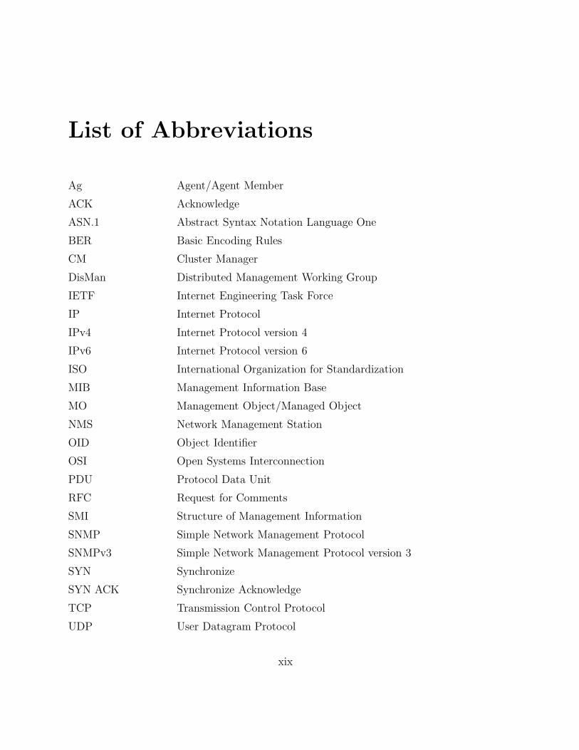
List of Abbreviations
Ag Agent/Agent Member
ACK Acknowledge
ASN.1 Abstract Syntax Notation Language One
BER Basic Encoding Rules
CM Cluster Manager
DisMan Distributed Management Working Group
IETF Internet Engineering Task Force
IP Internet Protocol
IPv4 Internet Protocol version 4
IPv6 Internet Protocol version 6
ISO International Organization for Standardization
MIB Management Information Base
MO Management Object/Managed Object
NMS Network Management Station
OID Object Identifier
OSI Open Systems Interconnection
PDU Protocol Data Unit
RFC Request for Comments
SMI Structure of Management Information
SNMP Simple Network Management Protocol
SNMPv3 Simple Network Management Protocol version 3
SYN Synchronize
SYN ACK Synchronize Acknowledge
TCP Transmission Control Protocol
UDP User Datagram Protocol
xix
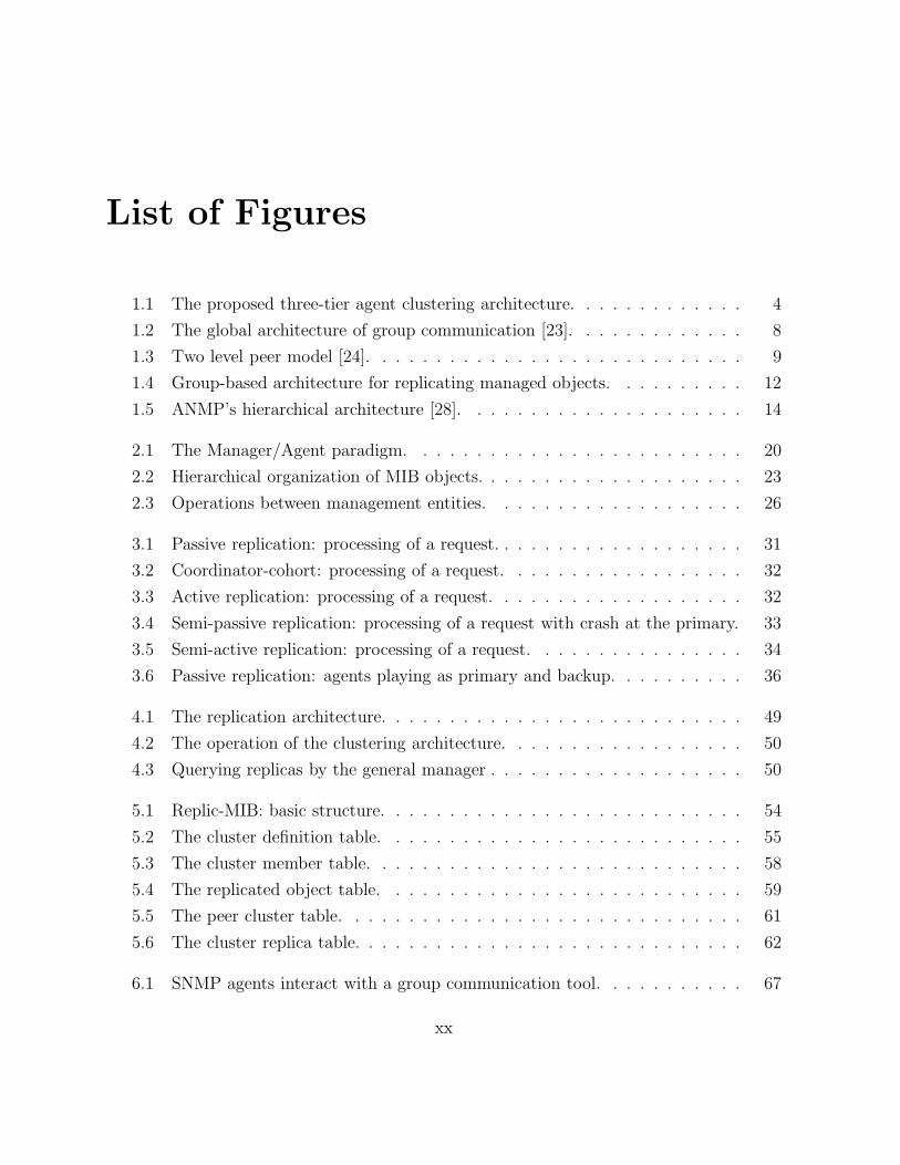
List of Figures
1.1 The proposed three-tier agent clustering architecture. . . . . . . . . . . . . 4
1.2 The global architecture of group communication [23]. . . . . . . . . . . . . 8
1.3 Two level peer model [24]. . . . . . . . . . . . . . . . . . . . . . . . . . . . 9
1.4 Group-based architecture for replicating managed objects. . . . . . . . . . 12
1.5 ANMP’s hierarchical architecture [28]. . . . . . . . . . . . . . . . . . . . . 14
2.1 The Manager/Agent paradigm. . . . . . . . . . . . . . . . . . . . . . . . . 20
2.2 Hierarchical organization of MIB objects. . . . . . . . . . . . . . . . . . . . 23
2.3 Operations between management entities. . . . . . . . . . . . . . . . . . . 26
3.1 Passive replication: processing of a request. . . . . . . . . . . . . . . . . . . 31
3.2 Coordinator-cohort: processing of a request. . . . . . . . . . . . . . . . . . 32
3.3 Active replication: processing of a request. . . . . . . . . . . . . . . . . . . 32
3.4 Semi-passive replication: processing of a request with crash at the primary. 33
3.5 Semi-active replication: processing of a request. . . . . . . . . . . . . . . . 34
3.6 Passive replication: agents playing as primary and backup. . . . . . . . . . 36
4.1 The replication architecture. . . . . . . . . . . . . . . . . . . . . . . . . . . 49
4.2 The operation of the clustering architecture. . . . . . . . . . . . . . . . . . 50
4.3 Querying replicas by the general manager . . . . . . . . . . . . . . . . . . . 50
5.1 Replic-MIB: basic structure. . . . . . . . . . . . . . . . . . . . . . . . . . . 54
5.2 The cluster definition table. . . . . . . . . . . . . . . . . . . . . . . . . . . 55
5.3 The cluster member table. . . . . . . . . . . . . . . . . . . . . . . . . . . . 58
5.4 The replicated object table. . . . . . . . . . . . . . . . . . . . . . . . . . . 59
5.5 The peer cluster table. . . . . . . . . . . . . . . . . . . . . . . . . . . . . . 61
5.6 The cluster replica table. . . . . . . . . . . . . . . . . . . . . . . . . . . . . 62
6.1 SNMP agents interact with a group communication tool. . . . . . . . . . . 67
xx

6.2 Cluster manager architecture. . . . . . . . . . . . . . . . . . . . . . . . . . 69
6.3 mcluster architecture. . . . . . . . . . . . . . . . . . . . . . . . . . . . . . . 70
6.4 A ReplicaTable row. . . . . . . . . . . . . . . . . . . . . . . . . . . . . . . 74
6.5 Set of IP objects: update frequency for 3 seconds of monitoring time. . . . 80
6.6 Set of TCP objects: update frequency for 3 seconds of monitoring time. . . 81
6.7 Set of UDP objects: update frequency for 3 seconds of monitoring time. . . 82
6.8 Latency of the ping-pong test. . . . . . . . . . . . . . . . . . . . . . . . . . 84
6.9 Latency required to the exchange of messages with 1 and 2 peer clusters. . 86
6.10 Latency required to the exchange of messages with 3 and 4 peer clusters. . 87
6.11 Latency required to the exchange of messages with 5 and 6 peer clusters. . 87
6.12 Average latency versus number of peer clusters. . . . . . . . . . . . . . . . 88
6.13 Exchange of messages among cluster managers with failure conditions. . . . 89
6.14 Three-way handshake. . . . . . . . . . . . . . . . . . . . . . . . . . . . . . 91
xxi
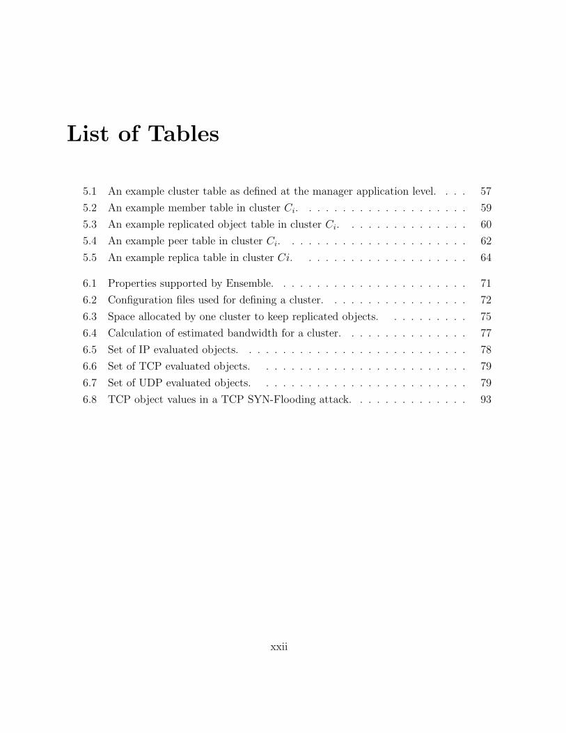
List of Tables
5.1 An example cluster table as defined at the manager application level. . . . 57
5.2 An example member table in cluster Ci. . . . . . . . . . . . . . . . . . . . 59
5.3 An example replicated object table in cluster Ci. . . . . . . . . . . . . . . 60
5.4 An example peer table in cluster Ci. . . . . . . . . . . . . . . . . . . . . . 62
5.5 An example replica table in cluster Ci. . . . . . . . . . . . . . . . . . . . 64
6.1 Properties supported by Ensemble. . . . . . . . . . . . . . . . . . . . . . . 71
6.2 Configuration files used for defining a cluster. . . . . . . . . . . . . . . . . 72
6.3 Space allocated by one cluster to keep replicated objects. . . . . . . . . . 75
6.4 Calculation of estimated bandwidth for a cluster. . . . . . . . . . . . . . . 77
6.5 Set of IP evaluated objects. . . . . . . . . . . . . . . . . . . . . . . . . . . 78
6.6 Set of TCP evaluated objects. . . . . . . . . . . . . . . . . . . . . . . . . 79
6.7 Set of UDP evaluated objects. . . . . . . . . . . . . . . . . . . . . . . . . 79
6.8 TCP object values in a TCP SYN-Flooding attack. . . . . . . . . . . . . . 93
xxii

Chapter 1
Introduction
Computer networks have become essential for enterprises and people. An adequate per-
formance of networks is often a pre-condition for the appropriate performance of the en-
terprises themselves. At the same time, networks are complex, being composed by both
hardware and software elements, and heterogeneous protocols produced by different orga-
nizations and vendors. Integrated network management systems include tools for network
monitoring and control of hardware, software elements, and heterogeneous protocols [1].
An efficient network management system must guarantee access to reliable information
to the managed components. The only way to maintain such information at the manager
application is the continuous monitoring of the system parameters that affect management
decisions [2]. The increasing complexity of managed network components and services
provided by such components may require monitoring more and more parameters.
A distributed three-layer architecture for distributed applications offers numerous ad-
vantages such as better scalability and availability. Using such kind of architecture, the
overall availability of a management system can be increased since different components of
the system may be executed at different locations. Besides, a failure of one of the compo-
nents would not imply the immediate unavailability of the whole service [3]. However, since
the dependencies among various components usually exist, even a single failure of a crucial
component may bring part of a management system to a halt or render it inaccurate.
1
2
The Simple Network Management Protocol (SNMP) is the management framework
standardized by the Internet Engineering Task Force (IETF) for IP networks [4, 5]. SNMP
is currently the de facto standard for network management and has been adopted by a
large number of organizations. Some of the issues that affect the scalability of monitoring
systems, such as the distance between the management station and the network elements,
have been addressed in the SNMP framework through the adoption of the three-tier archi-
tecture in the SNMP framework [6].
In a three-layer architecture, components in the middle layer can extend their func-
tionalities to perform activities previously executed only by the manager application. As
management activities are closer to the network elements, the traffic overhead on network
reduces, the control loops shortens, and new management activities can be included as
the replication of management data. Besides, middle-layer components of a management
system can operate in an autonomous manner. Thus, in case of given parts of a moni-
tored network becoming unavailable for some reason, operational management middle-layer
components can go on to monitor their partitions.
Replication is a natural manner to deal with failures. Many software replication tech-
niques have been proposed in order to provide the redundancy of both services and data
for distributed systems [7, 8, 9, 10]. Such techniques allow the operation of distributed sys-
tems even in presence of failures. While replication is a natural solution for fault-tolerance,
the implementation of a consistent replicated system is not so easy and requires certain
properties such as agreement and ordering [11].
Group communication is a communication infrastructure that offers high-level primi-
tives and has properties that allow the construction of fault-tolerant distributed systems
based on groups of cooperating processes [11, 12]. Group communication mechanisms
typically ensure agreement and ordering properties, among others. Agreement properties
ensure that all members agree on the delivery of some message, or on some value. Ordering
properties ensure that messages are delivered to all members in a certain order. Hence,
group communication can help in the design and implementation of distributed systems
that hold data, such as a network management system, for example.

1.1. Problem Description 3
As the functionality of network management systems includes fault and performance
management, among others, it is fundamental that these systems work correctly during the
occurrence of network faults even when some management components are faulty. Thus,
fault tolerance techniques have been applied in order to build reliable distributed network
management systems [13].
Fault management is one of the key functions of integrated network management sys-
tems. The purpose of fault management is to locate, determine the causes and, if possible,
correct network faults [1]. Different approaches have been proposed to accomplish this task,
including the application of system-level diagnosis for fault-tolerant network monitoring
[13, 14, 15], alarm correlation [16], and proactive fault detection [17], among others.
This work presents an agent clustering architecture that supports passive replication
[9] of managed objects. The architecture is introduced taking into consideration the widely
used SNMPv3 framework [4, 18]. However, the architecture is generic and can be applied
to any distributed management framework. Moreover, this work presents an SNMP frame-
work of the agent clustering architecture and a fault-tolerant fault management tool based
on this framework.
This chapter is organized as follows. First, we describe the problem addressed in our
work. Next, we introduce the proposed solution for the problem and the contributions of
this work. After, we present the related work. Finally, the organization of the remaining
chapters is presented.
1.1 Problem Description
The problem tackled in this work is to provide a reliable fault management mechanism
which allows a human manager to collect network information from a given network element
or set of network elements even if they have crashed or are unreachable.
Although there is a number of network monitoring systems, they usually only allow
the examination of managed objects of fault-free agents. However, as management objects
reflect the state of managed entities, it is often useful to examine the information at the
1.2. Solution Highlights and Contributions 4
MIB (Management Information Base) of a crashed agent with the purpose of determining
the reason why a given network element has crashed or is unreachable. Thus, the state
of the MIB’s objects may help the diagnosis process. Furthermore, there is currently no
standard way to examine MIB objects of faulty agents using SNMP, for instance.
1.2 Solution Highlights and Contributions
We present a new fault management architecture for the Internet standard Simple Network
Management Protocol (SNMP) based on agent clustering that supports passive replication
of managed objects. Specifically, this work has the purpose of defining a generic replication
architecture that can be applied to any distributed management framework.
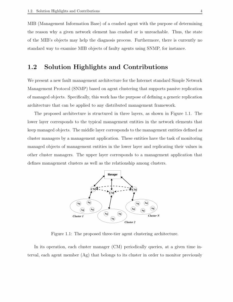
The proposed architecture is structured in three layers, as shown in Figure 1.1. The
lower layer corresponds to the typical management entities in the network elements that
keep managed objects. The middle layer corresponds to the management entities defined as
cluster managers by a management application. These entities have the task of monitoring
managed objects of management entities in the lower layer and replicating their values in
other cluster managers. The upper layer corresponds to a management application that
defines management clusters as well as the relationship among clusters.
Manager
Cluster 1 Cluster N
Cluster 2
Ag Ag
Ag Ag
Ag Ag
Ag
Ag
Ag Ag
Ag
CMCM
CM
Ag
Figure 1.1: The proposed three-tier agent clustering architecture.
In its operation, each cluster manager (CM) periodically queries, at a given time in-
terval, each agent member (Ag) that belongs to its cluster in order to monitor previously
1.2. Solution Highlights and Contributions 5
defined managed objects. A CM keeps at the local MIB instances of monitored objects
values and next replicates those values in other cluster managers which act as its peer
clusters.
The three-layer architecture allows the manager to query directly an specific agent in
order to obtain values of its objects or a given cluster manager and its peer clusters in
order to obtain values of replicated objects.
The clustering approach allows a specific cluster manager to keep replicated objects
from a number of other cluster managers, even if the set of replicated objects from each
one is different. Typically, a set of cluster managers replicate the same set of managed ob-
jects but it is possible to define different sets of managed objects for each cluster manager.
Thus, a cluster manager might be at the same time peer of a given cluster manager which
replicates only TCP (Transmission Control Protocol) objects, for example, and peer of an-
other cluster manager which replicates, for example, only UDP (User Datagram Protocol)
objects.
We propose the use of a group communication protocol [12, 20, 21] to guarantee the
consistency among replicated objects in peer clusters. Group communication protocols offer
properties and services, such as reliable multicast and group membership, among others,
that ensure the consistency of replicated data. However, the architecture allows the use of
different mechanisms to support the transmission of instances of replicated objects to the
peer cluster managers.
In summary, a cluster of agents provides fault-tolerant object functionality by replicat-
ing managed objects of a given collection of agents in agents that play the role of cluster
managers. In this way, the human manager or the manager application could access repli-
cated managed objects of a crashed agent of a given cluster through a peer cluster manager.
Furthermore, a cluster manager behaves as a cache of managed objects that may reduce
the impact of monitoring on network performance.

1.2. Solution Highlights and Contributions 6
The key contributions of this research are:
1. Definition of an architecture for reliable network fault management based on replica-
tion that allows the access to variables, i.e. replicated objects, of crashed or unreach-
able management entities. The architecture presents concepts of clustering and peers,
among others, in order to guarantee requirements such as scalability and consistency
of replicated data of network management systems.
2. Definition of an SNMP framework for replication of managed objects in SNMP agent
clusters. The framework specifies management objects that support the creation and
operation of agent groups, as well as the replication of managed objects in different
management entities. The MIB called Replic-MIB defines compliance modules for
both the SNMP manager and the cluster manager entities in a network management
system. Such modules define a collection of management objects for those SNMP
entities.
3. Implementation of a network fault management tool based on the agent clustering
framework. The tool was built using the public-domain NET-SNMP package [22]
and a group communication toolkit called Ensemble [21]. The tool extends new
functionalities to SNMP agents that allow the creation of SNMP agent clusters for
managed object replication. A group application called mcluster, which was built
using Ensemble, ensures a reliable communication facility among clusters.
4. Publication of an Internet-Draft named “A Clustering Architecture for Replicating
Managed Objects” as a Draft of the Distributed Management (DisMan) working group
[6] of the Internet Engineering Task Force (IETF). Particularly, the Draft describes
the components of the architecture, provides example of cluster configuration, and
the constraints and advices to the development of the architecture. An Internet-
Draft is the first step to propose an IETF standard to be published as an Request for
Comments (RFC) document. RFC documents are commonly adopted as standard
by Internet community.
1.3. Related Work 7
1.3 Related Work
A number of solutions have been proposed in the literature for the development of network
management systems. In this section, we present related work that has been shown to be
effective for building reliable distributed systems. Issues such as organizational models,
group communication facilities, and data replication, among others, are considered. We
describe the strategies of each related work and discuss how such approaches relate to the
present work.
1.3.1 A Group Communication Protocol for Distributed Network
Management Systems
Lee [23] introduces an efficient group communication protocol that provides ordered deliv-
ery of messages and supports overlapped grouping facility in a distributed network man-
agement system based on the hierarchical domain approach.
Guaranteeing reliable communication among the members of a group is one of the
problems that must be handled in designing fault tolerant distributed systems. Group
communication protocols provide a means for developing a reliable system without having
to build a number of underlying services such as multicast and membership. A reliable
group communication protocol typically guarantees the ordered delivery of messages among
the members of a group, but it also introduces protocol overhead in a system.
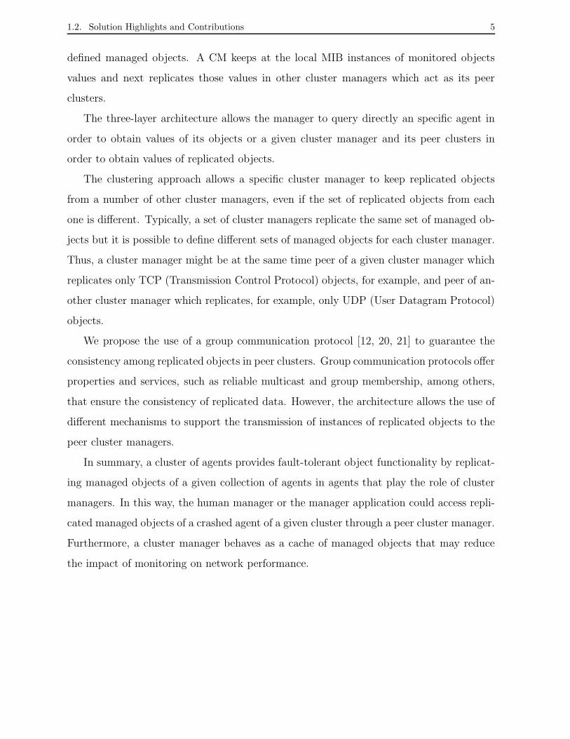
Lee has designed a distributed and hierarchical group communication protocol in which
the group communication function is split into three hierarchical entities called global group
manager (GGM), group communication daemon (GCD) and local group manager (LGM),
as shown in Figure 1.2. Such hierarchy helps to reduce the protocol overhead in supporting
an atomic and reliable group communication, even with the introduction of the overlapped
grouping concept, i.e. a given process may belong to two or more groups at the same time.
The GGM controls and manages all members of all groups through GCD or LGM
entities. A GCD resides in each host providing a group communication. It is responsible

1.3. Related Work 8
for creating and removing LGMs, and it also supports overlapped group management
functionality, i.e. the ability to control groups that contain members in common. An
LGM has the task of managing one or more process members of a specific group within a
host. As a group can be distributed over one or more hosts, in a single host there can be
various LGMs, each one supporting a different group.
GCD Global Communication DaemonGGM Local Group ManagerLGMGlobal Group Manager
GCD
GCD
LGMLGM LGM
LGM
LGMGCD
Communication Network
LGM LGM LGM
GGMGCDGCD
Figure 1.2: The global architecture of group communication [23].
The group communication is performed in three steps: the first step occurs between
process members and a LGM, the second between LGMs and a GCD and the last between
GCDs and the GGM. Therefore, an LGM controls process members which reside on a local
host, a GCD provides the overlapped group management function and the GGM manages
all LGMs in a network.
The architecture proposed in this thesis employs distributed and hierarchical approaches
similar to the ones described by Lee in order to reduce the communication overhead in
monitoring and replicating managed objects. Particularly the structure of the architecture
is split in three layers called the manager layer, the cluster layer, and the cluster member
layer. This structure provides simplicity and efficiency in replicating managed objects.
Furthermore, it allows groups to overlap, thus a process member can cooperate with various
groups that replicate different sets of managed objects.

1.3. Related Work 9
1.3.2 Multicast-SNMP to Coordinate Distributed Management
Agents
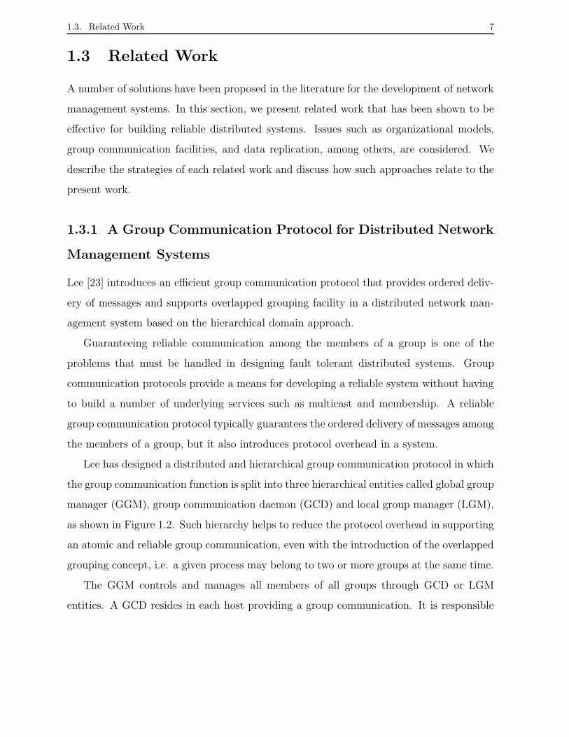
Schonwalder [24] introduces an approach for defining SNMP agent groups that implement
membership facilities on top of SNMP in order to build distributed management systems
based on cooperating management agents. His work describes how group membership
information and a master election algorithm can be built by using SNMP trap messages
encapsulated in UDP/IP 1 multicasts.
Group communication primitives allow the construction of fully distributed manage-
ment applications executed by autonomous cooperating agents. Schonwalder argues that
distributing management tasks to a number of cooperating agents provides some bene-
fits like the ability to implement load-balancing algorithms and the ability to replicate
functions in order to increase the fault tolerance of the management system itself. In his
approach, a delegation mechanism adds mobility to the management threads that has the
purpose of balancing the management load over a set of agents.
MIB
Agent
MIB
Agent
MIB
Agent
MIB
Agent
MIB
Agent
MIB
Agent
MIB
Agent
Peer-Agent
Peer-Agent
Peer-Agent
Figure 1.3: Two level peer model [24].
Schonwalder has implemented network management applications using the approach of
cooperating management agents structured on a peer-based model, as shown in Figure 1.3.
Schonwalder mentions that it is possible to combine a hierarchical model with a peer model
by implementing the nodes of a hierarchical structure using a set of cooperating peers, and
1UDP/IP - User Datagram Protocol/Internet Protocol

1.3. Related Work 10
thus achieving the advantages of both approaches. Schonwalder also mentions that more
study is needed to understand which properties of group communication protocols are actu-
ally needed by management applications and how the protocols behave in situations where
the network is unstable. As one of the main purposes of a network management system is
to help in situations where the network does not operate as designed, it might therefore
be useful to lower the consistency requirements usually found in distributed systems.
The architecture proposed in this work also combines the advantages of a peer model
along with a distributed and hierarchical model. Thus, our architecture allows the defi-
nition of a set of cooperating peer agents in an intermediate hierarchical structure. This
middle layer provides the ability to replicate managed objects. However, in contrast to
Schonwalder’s proposal, our architecture does not implement group communication pri-
mitives needed to coordinate distributed management agents. It assumes an underlying
reliable communication mechanism, such as group membership, to accomplish this task.
1.3.3 Group Communication as an Infrastructure for Distributed
Systems Management
Breitgand et al. [25] propose the use of group communication for facilitating development
of fault-tolerant, efficient and scalable distributed management solutions. They present a
generic management architecture in two layers. The architecture exploits a group commu-
nication service in order to minimize the communication costs and thus, it helps to preserve
complete and consistent operation despite of potential network partitions and site crashes.
The proposed management platform includes four reliable services that are the buil-
ding blocks for implementing distributed system management applications. Those services
support common management tasks as distributed configuration management, software
distribution, remote execution of the management actions, and efficient grouping of targets
with the same management requirements.
A prototype of the platform was partially implemented on which were addressed com-
mon management tasks such as simultaneous executions of the same operation in a group of
1.3. Related Work 11
workstations; software installation in multiple workstations; and consistent network table
management in order to improve the consistency of Network Information Service (NIS).
Breitgand et al. mention that the proposed platform could be extended to become
general enough to be applied to the problems of both distributed systems and network
management. One of the problems to solve is the scalability issue, since the architecture in
two layers based on the client-server paradigm may not provide the appropriate scalability.
In order to solve scalability problems, they have suggested extending the platform to include
a reliable mid-level manager service that facilitates a development of reliable hierarchical
management applications. This mid-level manager could be used for efficient aggregation
of low-level management data to higher-level data that would be presented to a higher-level
management application.
Our replication architecture includes a mid-level manager similar to the one suggested
by Breitgand et al. Our purpose is to provide an efficient aggregation mechanism for
management objects monitored at a lower level that are replicated at other middle level
managers. Our architecture provides scalability and flexibility in order to replicate different
sets of managed objects. Besides, keeping a collection of important managed objects closer
to the management application allows the reduction of the traffic overheard and improves
the response time in querying those managed objects.
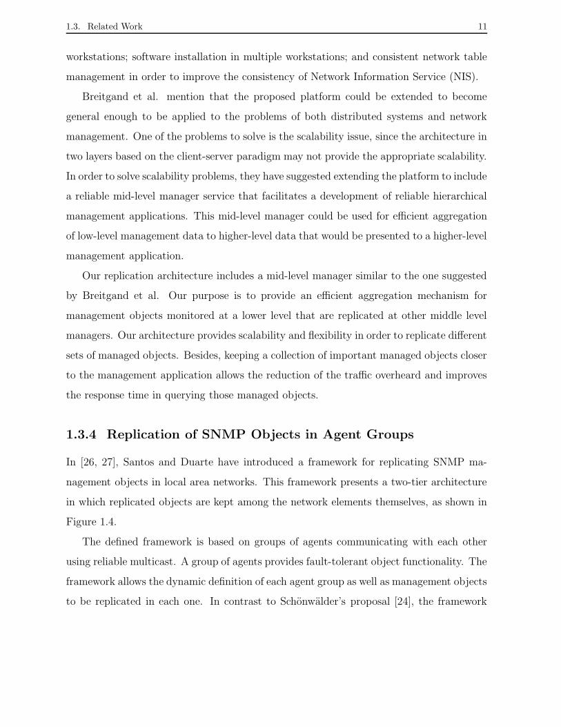
1.3.4 Replication of SNMP Objects in Agent Groups
In [26, 27], Santos and Duarte have introduced a framework for replicating SNMP ma-
nagement objects in local area networks. This framework presents a two-tier architecture
in which replicated objects are kept among the network elements themselves, as shown in
Figure 1.4.
The defined framework is based on groups of agents communicating with each other
using reliable multicast. A group of agents provides fault-tolerant object functionality. The
framework allows the dynamic definition of each agent group as well as management objects
to be replicated in each one. In contrast to Schonwalder’s proposal [24], the framework

1.3. Related Work 12
considers that a membership service under SNMP guarantees reliable communication.
Request
Group
Request
Manager
Agent
Agent
Update
Agent
Agent
Figure 1.4: Group-based architecture for replicating managed objects.
The introduced SNMP service allows replicated MIB objects of crashed agents to be
accessed through working agents. The service is based on cooperating groups of SNMP
agents defined over a group communication tool. The main part of the MIB describing
the framework consists of three dynamic tables. The first table contains the definition
of multiple agent groups; the second table contains the specification of objects that are
replicated in each group, and the last table keeps the replicated objects in all members
of all groups. When the system is initialized, the replicated object table is automatically
built from the other two tables and replicated throughout the group. In this way, the
replicated object table enables a manager to access replicated objects through any agent of
a given group. However, several new framework requirements were identified to extend this
service to large networks. Issues like network elements with different processing capacity
and required bandwidth might often interfere on network data consistency, consequently
affecting the reliability and scalability of a network monitoring system.
In the two-tier architecture for cooperating groups of SNMP agents, all members of a
group need to replicate objects at each time interval as well as to keep replicated objects
from other agents. To accomplish this task, each agent needs to have enough processing ca-
pacity. Furthermore, network resources are also required to transmit replication messages.
The issues mentioned above can restrict the number of agents at a given group or even the
number of agent groups. Hence, in order to solve those issues, other approaches presented
at literature, such as the clustering approach, have been included in that framework. They
1.3. Related Work 13
have contributed for defining the replication architecture proposed in this work as well as
a new framework.
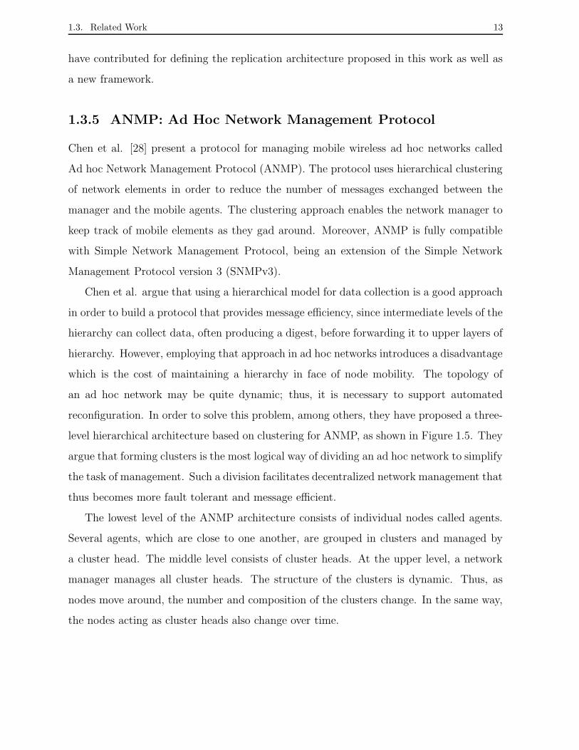
1.3.5 ANMP: Ad Hoc Network Management Protocol
Chen et al. [28] present a protocol for managing mobile wireless ad hoc networks called
Ad hoc Network Management Protocol (ANMP). The protocol uses hierarchical clustering
of network elements in order to reduce the number of messages exchanged between the
manager and the mobile agents. The clustering approach enables the network manager to
keep track of mobile elements as they gad around. Moreover, ANMP is fully compatible
with Simple Network Management Protocol, being an extension of the Simple Network
Management Protocol version 3 (SNMPv3).
Chen et al. argue that using a hierarchical model for data collection is a good approach
in order to build a protocol that provides message efficiency, since intermediate levels of the
hierarchy can collect data, often producing a digest, before forwarding it to upper layers of
hierarchy. However, employing that approach in ad hoc networks introduces a disadvantage
which is the cost of maintaining a hierarchy in face of node mobility. The topology of
an ad hoc network may be quite dynamic; thus, it is necessary to support automated
reconfiguration. In order to solve this problem, among others, they have proposed a three-
level hierarchical architecture based on clustering for ANMP, as shown in Figure 1.5. They
argue that forming clusters is the most logical way of dividing an ad hoc network to simplify
the task of management. Such a division facilitates decentralized network management that
thus becomes more fault tolerant and message efficient.
The lowest level of the ANMP architecture consists of individual nodes called agents.
Several agents, which are close to one another, are grouped in clusters and managed by
a cluster head. The middle level consists of cluster heads. At the upper level, a network
manager manages all cluster heads. The structure of the clusters is dynamic. Thus, as
nodes move around, the number and composition of the clusters change. In the same way,
the nodes acting as cluster heads also change over time.

1.3. Related Work 14
Cluster head
AgentsCluster
Manager
Figure 1.5: ANMP’s hierarchical architecture [28].
In order to support clustering in ad hoc networks, Chen et al. developed two clustering
approaches: graph-based clustering and geographical-based clustering. The first approach
models the network as a graph and forms clusters based on the graph topology. The second
approach uses a global positioning system (GPS) information to divide the network into
clusters.
ANMP extends the MIB’s used in SNMP to include ad hoc network specific information.
Chen et al. added a new MIB group called anmpMIB to the MIB-2 of SNMP for supporting
ad hoc network management functions. Thus, every node in the network locally runs an
ANMP entity. This new MIB contains, among its subgroups, a group that defines objects
related to the topology information of the ad hoc network, allowing each node to keep a list
of all neighbors as well as clustering protocols which may be used for topology maintenance.
The architecture of management elements clustering for the management of data repli-
cation proposed in this work applies some of the approaches described by Chen et al. Those
approaches focus on solving the requirements of scalability, consistency, and processing ca-
pacity among the network elements in order to extend the object replication service to
large networks.
We have used a clustering approach in our work to reduce the number of messages
exchanged among the network elements and thus to decrease the impact of replication
on network performance. Like in ANMP, we define an intermediate level of management.

1.3. Related Work 15
This middle level consists of network elements called cluster managers that are capable
of monitoring and replicating objects among them. Furthermore, the architecture splitted
into three levels provides the scalability needed for clustering network elements with either
homogeneous or heterogeneous characteristics. Hence, a manager application can define
different sets of clusters in which each cluster represents a set of network elements and
management objects to be replicated. We also introduce a new MIB group called Replic-
MIB for supporting managed object replication in agent cluster. The specification of the
Replic-MIB takes into account the SNMP framework.
1.3.6 Network Control and Management of a Reconfigurable WDM
Network
Wei et al. [29] describe a management system based on CORBA and the group commu-
nication tool Isis [12], deployed on a set of two management stations (NMS’s) and five
managed network elements, on top of a WDM (Wavelength Division Multiplexing) net-
work. Robustness of the management functionality is provided through the object group
mechanism which actively replicates management software objects across the two manage-
ment stations. Thus, in case of one management station crashes, the other station takes
over seamlessly. Except for the administrator front-end graphical interface, all other man-
agement objects, i.e. connection, fault and configuration objects, are replicated and span
across both management stations. In this way, crashing of a management process on one
management station can be tolerated, without affecting the continuous operation of the
management system.
In our architecture, we allow the replication of management objects not management
functions. We introduce the passive replication technique which better supports the usage
of object groups like views over the whole management objects [12]. The passive replication
tecnique selects one replica in order to play as primary replicas, and the other replicas play
as backups. Thus, each agent group can replicate a specific collection of objects according to
its goal. Hence, not all management objects are replicated. This replication strategy allows

1.4. Thesis Organization 16
copies of objects replicated from each agent group to be deployed to different management
entities in the system.
1.4 Thesis Organization
The rest of the thesis is organized as follows. Chapter 2 introduces the network ma-
nagement paradigm based on SNMP. Chapter 3 presents an overview of failure models,
replication techniques and group membership that are commonly used for the develop-
ment of reliable distributed applications. Chapter 4 defines requirements of the proposed
model and describes the agent clustering architecture for replicating management objects.
Chapter 5 describes an SNMP framework for replication of managed objects in agent clus-
ters. In chapter 6, we present a practical fault network management tool based on the
SNMP agent clustering framework. Furthermore, we introduce an evaluation of the tool
which includes a study of the resource consumption, a performance analysis, and a brief
study of the availability of the tool. An application example shows how the tool can help
to determine the occurrence of TCP SYN-Flooding attacks. Chapter 7 concludes the thesis
and presents directions for future work.
Chapter 2
Network Management & The SNMP
Framework
Computer networks are increasingly more complex and larger. These networks are typi-
cally composed of hardware, software, and heterogeneous protocols produced by different
organizations and vendors. Network Management systems are used to control and monitor
network elements and the system as a whole [1]. SNMP (Simple Network Management
Protocol) is the de facto standard for network management nowadays, and a large number
of organizations have adopted it. Thus, using the SNMP Framework as reference, we will
propose an agent clustering architecture for building reliable network management systems.
This chapter defines the goals of network management systems and presents the classifi-
cation of network management functionality proposed by ISO (International Organization
for Standardization). Such classification still remains current, although other function-
alities have been included over time. Section 2.2 presents an overview of the Internet-
standard Management Framework, widely known as the SNMP Framework, that describes
the SNMP management architecture, the Structure of Management Information (SMI), the
Internet Management Information Base (MIB), and the SNMP protocol used by managers
and agents to communicate. In addition, this section presents a brief discussion about the
framework’s evolution trends, including the SNMPv3.
17

2.1. Network Management 18
2.1 Network Management
Network Management is needed to control and monitor the operation of the network ac-
cording to changing user requirements. Management includes the initialization, monitoring
and modification of both hardware and software elements in the network [30]. Such ele-
ments can be computers, routers, bridges, hubs, modem, consoles, and printers, among
others.
ISO (International Organization for Standardization) has proposed a classification of
network management functionalities into five areas: fault, performance, configuration, se-
curity, and accounting management. These functionalities were proposed as part of the
OSI (Open Systems Interconnection) systems management specification, but they have
been widely accepted to describe the requirements for any network management system
[31]. The function of each area is described below:
• Fault management: allows the detection, isolation, and correction, if possible, of
abnormal operations of the network (network elements and services).
• Performance management: allows performance monitoring and evaluation of the
network.
• Configuration management: allows the human manager to reconfigure the network
from a manager station in order to guarantee continuous operation and quality of
service.
• Security management: includes procedures to protect the system from unauthorized
access.
• Accounting management: enables charges and costs to be assigned for network usage.
In the next section, we present an overview of the Internet Standard Network Man-
agement Framework, also known as the SNMP (Simple Network Management Protocol)
Framework.

2.2. SNMP Framework 19
2.2 SNMP Framework
SNMP (Simple Network Management Protocol) [4, 32, 33, 34] is the de facto standard for
network management nowadays. A large number of organizations have adopted SNMP in
order to manage their networks. A vast number of network devices such as routers, bridges,
hubs, and operating systems from different vendors offer support for SNMP.
As networks expand and become mission critical, the need for an integrated system to
allow network monitoring and control becomes critical [35]. Networks are made up of he-
terogeneous elements, being based on computer and communication technologies produced
by different organizations and vendors. Thus, it is important that network management
systems be based on international open standards, shared by all technologies. SNMP is an
open framework developed by the TCP/IP community to allow the integrated management
of highly heterogeneous internets.
Although SNMP is a simple protocol, its huge success is not due to a lack of more
complex alternatives. SNMP’s simplicity, is, to the opposite, one of the reasons why the
protocol has been so widely deployed. As the impact of adding network management to
managed nodes must be minimal, avoiding complicated approaches is a basic requirement
of any network management model. The simplicity of SNMP has guaranteed its efficiency
and scalability. Although there is a number of areas in which SNMP has shown deficiencies,
the set of standards has been evolving: new versions and new solutions are being developed
continuously.
In this section, we provide an overview of the SNMP management architecture, includ-
ing the data definition language called Structure of Management Information (SMI), the
Management Information Base (MIB), the management protocol, and conclude examining
the framework’s evolution trends.
2.2.1 SNMP Architecture
SNMP is originally based on the manager-agent paradigm, in which the network is moni-
tored and controlled through management applications called managers running in a Net-

2.2. SNMP Framework 20
work Management Station (NMS), and agents running in nodes and network devices, also
known as managed devices. In order to simplify our understanding, throughout this sec-
tion, We call agents all nodes and network devices that contain an agent. As shown in
Figure 2.1, each agent keeps management information stored in a local Management Infor-
mation Base (MIB). The NMS also keeps a MIB. A MIB may include a large amount of
management information such as the number of packets received by an agent and the sta-
tus of its interfaces. The NMS and the agents communicate using a network management
protocol.
MIB
MIB
AgentMIB
AgentMIB
NMS
Agent
SNMP
TrapSNMPTrap
SNMPTrap
SNMP
SNMPquerySNMP
querySNMP
query
Server SNMP SNMP
Server SNMP Server
Client APPLICATIONS
MANAGEMENT
Figure 2.1: The Manager/Agent paradigm.
The NMS runs a collection of management applications, which provides fault, perfor-
mance, configuration, security, and accounting management [36]. Agents run on computers
and network devices such as routers, bridges, hubs, that are equipped with SNMP so that
they can be managed by the NMS. Each agent replies to SNMP queries, and may issue
asynchronous alarms, called traps, to the NMS reporting exceptions, for example, when
management objects indicate that an error has occurred. Agents run an SNMP server, and
the NMS runs SNMP client applications.
An SNMP MIB is a set of management objects (MO’s). Each object is a data variable

2.2. SNMP Framework 21
that represents one characteristic of the managed element. The MIB’s are standard, and
different types of agents have MIB’s containing different objects. The NMS can cause an
action to take place at an agent or can change and agent’s configuration by modifying the
value of specific variables.
The NMS and the agents communicate using a network management protocol called
SNMP. SNMP contains three general types of operations: get, with which the NMS queries
an agent for the value of a given management object; set, with which the NMS writes the
value of a given management object on a given agent; and trap, with which an agent notifies
the NMS about a significant event.
SNMP is an application layer protocol of the TCP/IP protocol suite. It runs on top of
UDP (User Datagram Protocol), a connectionless transport protocol, which runs on top of
IP (Internet Protocol).
The reason for which a connectionless protocol was chosen is that network management
must be very resilient to faults over the network. A connection may have problems to be
established if there is a fault. Furthermore, a connection-oriented approach masks a number
of network problems for the application, because it does retransmission and flow control
automatically. Network management cannot have these problems hidden from it.
There are two strategies usually employed by the NMS to monitor the network: polling
and alarm management. The NMS polls agents regularly at specific time intervals querying
for management objects. The interval may vary depending on the object or the network
state. On the other hand, alarm management is based on traps sent by agents to the NMS
when threshold conditions are reached. In general, network management systems employ
a combination of polling and alarm management [37].
If the NMS monitors a large number of agents and each agent maintains a large number
of objects, then it may become impractical to regularly poll all agents for all of their data
[18]. However, trap processing also has problems of its own. As agents must generate
events when thresholds are achieved, they must continuously monitor the value of the
management objects. This process may have a bad impact on the performance of the
agent. Furthermore, when there is a fault in the network, the NMS is usually flooded with
2.2. SNMP Framework 22
alarms sent from agents that have different perspectives of the problem, and diagnosis can
be difficult in those circumstances. If the network problem is congestion, traps will make
it even worse. The SNMP community favors pollings over traps [38].
2.2.2 Structure of Management Information
Management information is a key component of any network management system. In the
SNMP framework, information is structured as a collection of management objects (MO’s)
stored at the MIB. Each MO refers to a MIB variable. Each device in the network keeps a
MIB that has information about the managed resources of that device. The NMS monitors
a resource by reading its corresponding MO’s current value, and controls the resource by
writing a new value to the MO. In SNMP, the only data types supported are simple scalars
and data arrays.
The Structure of Management Information (SMI) [39] defines the rules for describing
management information. The SMI defines the data types that can be used in the MIB,
and how resources within the MIB are represented and identified. It was built to emphasize
simplicity and extensibility. The SMI allows the description of management information
independently of implementation details.
The SMI is defined using a restricted subset of ASN.1 (Abstract Syntax Notation Lan-
guage One). ASN.1 is an ISO formal language that defines the abstract syntax of applica-
tion data. Abstract syntax refers to the generic structure of data, as seen by an application,
independent of any encoding techniques used by lower level protocols. An abstract syntax
allows data types to be defined and values of those types to be specified independently of
any specific representation of the data. ASN.1 is employed to define not only the manage-
ment objects, but also the Protocol Data Units (PDU’s) exchanged by the management
protocol.
There must be a mapping between the abstract syntax and an encoding, which is used
to store or transfer the object. The encoding rules used by SNMP are called BER (Basic
Encoding Rules), which, like ASN.1, is also an ISO standard. BER describes a method for

2.2. SNMP Framework 23
encoding values of each ASN.1 type as an octet string. The encoding is based on the use
of a type-length-value structure to encode any ASN.1 definition. The type includes the
ASN.1 type plus its class, the length indicates the length of the actual value representation,
and the value is a string of octet. The structure is recursive, so that complex types are
also represented using this basic rule.
Object Identifiers
The SMI has, among others, the task of defining unique identifiers for management
objects. Thus, there must be a consensus throughout systems about what each object is
used to represent, and how objects are accessed.
ccitt(0)
iso(1)
iso-ccitt(2)
standard(0)
authority(1)
member(2)
org(3)
dod(6)
internet(1)
directory(1)
mgmt(2)
experimental(3)
private(4)
security(5)
snmpV2(6)
mib-2(1)
system(1)
interface(2)
.... sample(11)
Figure 2.2: Hierarchical organization of MIB objects.
Each object identifier is a sequence of labels, which translates to a sequence of integers.
Each object is organized in a tree, such that the integer sequence corresponds to the path
from the root of the tree up to the point where the object is defined. It is important to
remember that these objects and their identifiers are standard, defined by the authority
who is responsible for the management framework.

2.2. SNMP Framework 24
The virtual root of the tree of objects is assigned to the ASN.1 standard, as shown in
Figure 2.2. In the first level, there are three possible subtrees: ccitt, iso and joint-iso-ccitt.
Each SNMP MIB is defined under the internet subtree, which is under the iso subtree,
being referred as iso.org.dod.internet and translated as .1.3.6.1.
The SMI defines under the internet subtree the following subtree among others:
• mgmt: employed for standard Internet management objects. The mgmt subtree
contains the standard MIB, under the subtree mib-2.
• experimental: employed to identify experimental objects.
• private: employed by vendors and organizations to attend private needs. This sub-
tree contains a subtree called enterprises under which a subtree is allocated to each
organization that registers for an enterprise object identifier.
MIB-2
MIB-2, defined in Request for Comments (RFCs) 2011, 2012, and 2013 [34, 40, 41], is the
current standard TCP/IP protocol’s MIB. The mib-2 subtree is under the mgmt subtree,
being referred as iso.org.dod.internet.mgmt.mib-2 or 1.3.6.1.2.1. Within the MIB, objects
are usually defined in groups on which each group has a specific purpose.
• system: overall information about the managed device itself; for example, the variable
sysUpTime shows how long ago the device was last re-initialized.
• interfaces: information about each of the interfaces from the agent to the network
and its traffic; for example, the variable ifNumber gives the number of interfaces of
the agent to the network.
• at (address translation): contains address resolution information, used for mapping IP
address into media-specific address. For example, the variable atPhysAddress gives
the media address for a given interface, and the variable atNetAddress gives the IP
address.
2.2. SNMP Framework 25
• ip, icmp, tcp, udp, egp, and snmp: every group has information about that protocol’s
implementation and behavior on the system. For example, the variable ipInDelivers
gives the total number of input datagrams successfully delivered to IP user-protocols.
• transmission: gives information concerning the transmission schemes and access pro-
tocols at each system interface, used for media-specific MIBS, as for X.25, Token
Ring, FDDI, among others.
2.2.3 The SNMP Protocol
The SNMP protocol is employed by managers and agents to communicate management
information. It is used by managers to query and control agents, and by agents to issue
traps and reply to queries. Version 2 of SNMP also allows managers to communicate
among themselves. SNMP became a full Internet standard in 1990 [33]. The protocol has
since evolved, but “basic” SNMP is in widespread use, having been adopted by dozens of
organizations worldwide. For the implementations described in chapter 6, SNMPv3 was
used.
SNMP provides a collection of operations performed between management entities, as
described below and shown in Figure 2.3, in order to communicate management informa-
tion.
• Get: requests the value of a given management object;
• GetNext: requests the value of next management object;
• Bulk: requests a set of management objects at the same time;
• Set: stores a new value for a given management object;
• Response: responses operations described before;
• Trap: an agent sends the value of a given management object to a manager when
exceptional events have occurred;
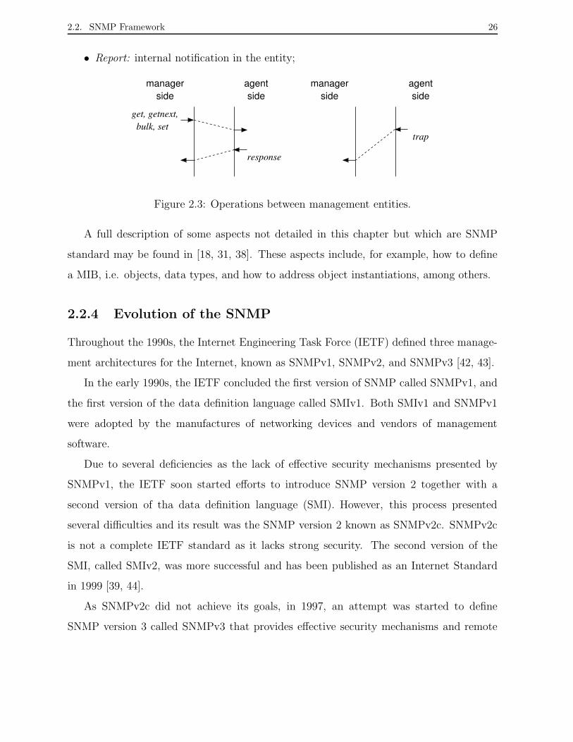
2.2. SNMP Framework 26
• Report: internal notification in the entity;
managerside
agentside
agentside
managerside
get, getnext,bulk, set
response
trap
Figure 2.3: Operations between management entities.
A full description of some aspects not detailed in this chapter but which are SNMP
standard may be found in [18, 31, 38]. These aspects include, for example, how to define
a MIB, i.e. objects, data types, and how to address object instantiations, among others.
2.2.4 Evolution of the SNMP
Throughout the 1990s, the Internet Engineering Task Force (IETF) defined three manage-
ment architectures for the Internet, known as SNMPv1, SNMPv2, and SNMPv3 [42, 43].
In the early 1990s, the IETF concluded the first version of SNMP called SNMPv1, and
the first version of the data definition language called SMIv1. Both SMIv1 and SNMPv1
were adopted by the manufactures of networking devices and vendors of management
software.
Due to several deficiencies as the lack of effective security mechanisms presented by
SNMPv1, the IETF soon started efforts to introduce SNMP version 2 together with a
second version of tha data definition language (SMI). However, this process presented
several difficulties and its result was the SNMP version 2 known as SNMPv2c. SNMPv2c
is not a complete IETF standard as it lacks strong security. The second version of the
SMI, called SMIv2, was more successful and has been published as an Internet Standard
in 1999 [39, 44].
As SNMPv2c did not achieve its goals, in 1997, an attempt was started to define
SNMP version 3 called SNMPv3 that provides effective security mechanisms and remote
2.3. Conclusion 27
administration capabilities [4]. Most current SNMP-based systems are built with this third
version of the framework.
2.3 Conclusion
In this chapter, we introduced the purpose of network management systems and presented
the traditional classification of network management functionality proposed by ISO (Inter-
national Organization for Standardization). Next, we presented the SNMP Framework.
SNMP has been widely adopted by different organizations at the management of their
networks, being a de facto standard. We presented an overview of the SNMP Framework
focusing on the main components: the SNMP architecture, the SMI, and the SNMP pro-
tocol. The SNMP architecture is originally based on the manager-agent paradigm. In this
architecture, managers, which run in a Network Management Station, and agents, which
run in managed devices, accomplish the network management. The SMI is a data def-
inition language that defines the rules for describing management information, allowing
the description of management information independently of implementation details. The
SNMP protocol provides the communication between managers and agents. Further, it
allows managers to query and control agents, and agents to issue trap messages and reply
to queries. We also presented a brief discuss over the framework’s evolution trends that
include SNMPv3.
Throughout the thesis, we utilize the SNMP framework to describe an architecture of
management entities clustering for replication of managed objects.

Chapter 3
Replication & Group Communication
A major problem inherent to distributed systems is their potential vulnerability to fai-
lures. Indeed, whenever a single element fails, the availability of the whole system may
be damaged. On the other hand, the distributed nature of systems provides the means
to increase they dependability, which means that reliance can justifiably be placed on the
service their deliver [45]. In distributed systems, it is possible to introduce redundancy
and, thus, make the overall system more reliable than its individual parts [46].
Redundancy is usually introduced by replication of components or services. Although
replication is an intuitive and readily understood concept, its implementation in a dis-
tributed system requires sophisticated techniques [8]. Active and passive replication are
two major classes of replication techniques to ensure consistency between replicas. Both
techniques are useful since they have complementary qualities, and many other replication
techniques extend such qualities.
This chapter presents an overview of some replication techniques showing their diffe-
rences, similarities, and sometimes their applications in distributed systems. Many of those
techniques have been described by Defago [46]. Section 3.1 describes the existing failure
models. Section 3.2 presents replication techniques and their usage in a client-server model.
Section 3.3 describes the group abstraction and the role of the group membership service for
building reliable distributed applications. Moreover, group communication systems, such
28
3.1. Failure Models 29
as the Ensemble system, are mentioned. Section 3.4 proposes the use of passive replication
and group abstraction for building reliable network management systems.
3.1 Failure Models
The reliability of a component or system is its ability to function correctly over specified
period of time. The availability of a system is defined to be the probability that system
is working at given time, regardless of the number of times it may have failed and been
repaired [19]. In a distributed computing system, it is impossible to tolerate all failures
since there is always a nonzero probability that all will fail, either independently or due
to a common cause. Therefore, the goal of fault tolerance is to improve the reliability and
availability of a system to a specified level by tolerating a specified number of selected types
of failures. Failure models have been developed to describe abstractly the effects of failures.
The use of such a model simplifies the programmer’s task by allowing the program to be
designed to cope with this abstract model rather than trying to cope with the different
individual causes of failures.
A hierarchy of failure models has been developed for use in different application ar-
eas [47]. The broadest failure model is the Byzantine or arbitrary failure model where
components fail in an arbitrary way [48]. This model accommodates all possible causes
of failures, including malicious failures where a machine actively tries to interfere with
the progress of a computation. Naturally, the systems based on this failure model are
complicated and expensive to execute. The Byzantine with authentication failure model
allows the same type of failure, but with the added assumption that a method is available
to identify reliably the sender of a message. This assumption substantially simplifies the
problem. The timing or performance failure model assumes a component will respond with
the correct value, but not necessarily within a given time specification [49]. The omission
failure model assumes a component may never respond to an input [49]. The crash or
fail-silent failure model assumes that the only way a component can fail is by ceasing to
operate without making any incorrect state transitions [50]. Finally, the fail-stop failure
3.2. Replication Techniques 30
model adds to the crash model the assumption that the component fails in a way that is
detectable by other components [51]. A more complete classification of failure models and
their relations can be found in [52]; numerous other classifications based on factors such as
duration and cause have also been proposed [45]. In general, more inclusive is the failure
model, higher is the probability that it covers all failures that are encountered, but at a
cost of increased processing time and communication.
3.2 Replication Techniques
Replication techniques applied to critical components of systems are an approach to in-
troduce redundancy. Replication is actually the only mechanism for fault tolerance that
simultaneously increases the reliability and the availability of a system [7]. Replication is
the process of making a copy (replica) of resources, processes or data. In particular, the
kind of replica considered in this thesis is management data, specifically, management ob-
jects. There are two basic techniques for replication: active and passive replication. Both
techniques are useful since they have complementary qualities. Replication techniques such
as coordinator-cohort, semi-passive, and semi-active are variants of those techniques.
In this section, we discuss the differences and similarities of those replication techniques.
The application model taken into account in all replication techniques is the client-server
model. Furthermore, the server is composed of three replica entities named P1, P2, and
P3. It is also assumed that only the client makes requests to the server, and a request is a
processing required at the server that may or not involve state changes among the replicas.
3.2.1 Passive Replication
The passive replication technique is also known as the primary-backup approach [53]. This
technique selects one replica in order to play as primary, and the other replicas play as
backups. As Figure 3.1 shows, the client only interacts with the primary (P1), i.e. it sends
its request to the primary. The primary then processes the request, and next sends update

3.2. Replication Techniques 31
messages to the backups (P2 and P3) in order to keep a consistent state among replicas.
Once the backups have been updated, the primary then sends the response to the client.
As all backups interact directly only with the primary, every time that the primary
fails, the backups must detect the failure and run an election algorithm, such as a leader
election algorithm, in order to determine which one will become the new primary. Thus,
this replication technique has two drawbacks: (1) the reconfiguration procedure in order
to elect a new primary is typically costly, and (2) in case of the primary fails, the client
needs to be informed about the new primary in order to resend its request.
P1
P2
P3
Backup
Primary
Backup
Processing State update
Client
Request Response
Update
Figure 3.1: Passive replication: processing of a request.
3.2.2 Coordinator-Cohort
Coordinator-cohort [54] is a variant of passive replication designed in the context of the
Isis group communication system [55]. As passive replication, it is based on the principle
that only one of the replicas should process the requests. Thus, at this strategy, one of the
replicas is designed as the coordinator (primary) and the others are the cohorts (backups).
Unlike a passive replication, a client sends its request to the whole group of replicas: P1,
P2, and P3, as shown in Figure 3.2. The coordinator (P1) then handles the request and
next sends update messages to the cohorts (P2 and P3) in order to make them updated.
If the coordinator fails, the other group members elect a new coordinator, and it takes over
the processing of the request.
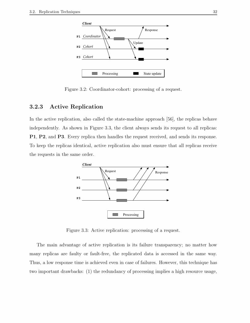
3.2. Replication Techniques 32
P1
P2
P3
Processing State update
Client
Coordinator
Cohort
Cohort
Request Response
Update
Figure 3.2: Coordinator-cohort: processing of a request.
3.2.3 Active Replication
In the active replication, also called the state-machine approach [56], the replicas behave
independently. As shown in Figure 3.3, the client always sends its request to all replicas:
P1, P2, and P3. Every replica then handles the request received, and sends its response.
To keep the replicas identical, active replication also must ensure that all replicas receive
the requests in the same order.
P1
P2
P3
Client
Processing
ResponseRequest
Figure 3.3: Active replication: processing of a request.
The main advantage of active replication is its failure transparency; no matter how
many replicas are faulty or fault-free, the replicated data is accessed in the same way.
Thus, a low response time is achieved even in case of failures. However, this technique has
two important drawbacks: (1) the redundancy of processing implies a high resource usage,
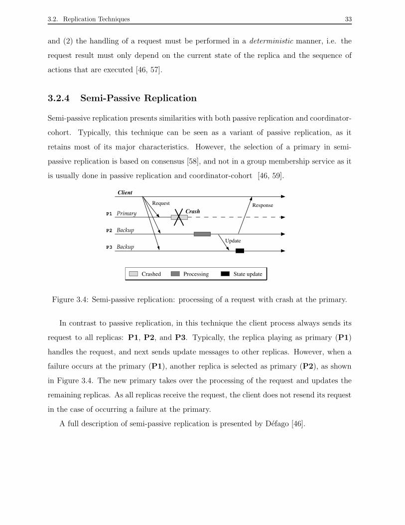
3.2. Replication Techniques 33
and (2) the handling of a request must be performed in a deterministic manner, i.e. the
request result must only depend on the current state of the replica and the sequence of
actions that are executed [46, 57].
3.2.4 Semi-Passive Replication
Semi-passive replication presents similarities with both passive replication and coordinator-
cohort. Typically, this technique can be seen as a variant of passive replication, as it
retains most of its major characteristics. However, the selection of a primary in semi-
passive replication is based on consensus [58], and not in a group membership service as it
is usually done in passive replication and coordinator-cohort [46, 59].
PrimaryP1
P2
P3
Backup
Backup
Client
Request
Crash
Crashed Processing State update
Response
Update
Figure 3.4: Semi-passive replication: processing of a request with crash at the primary.
In contrast to passive replication, in this technique the client process always sends its
request to all replicas: P1, P2, and P3. Typically, the replica playing as primary (P1)
handles the request, and next sends update messages to other replicas. However, when a
failure occurs at the primary (P1), another replica is selected as primary (P2), as shown
in Figure 3.4. The new primary takes over the processing of the request and updates the
remaining replicas. As all replicas receive the request, the client does not resend its request
in the case of occurring a failure at the primary.
A full description of semi-passive replication is presented by Defago [46].
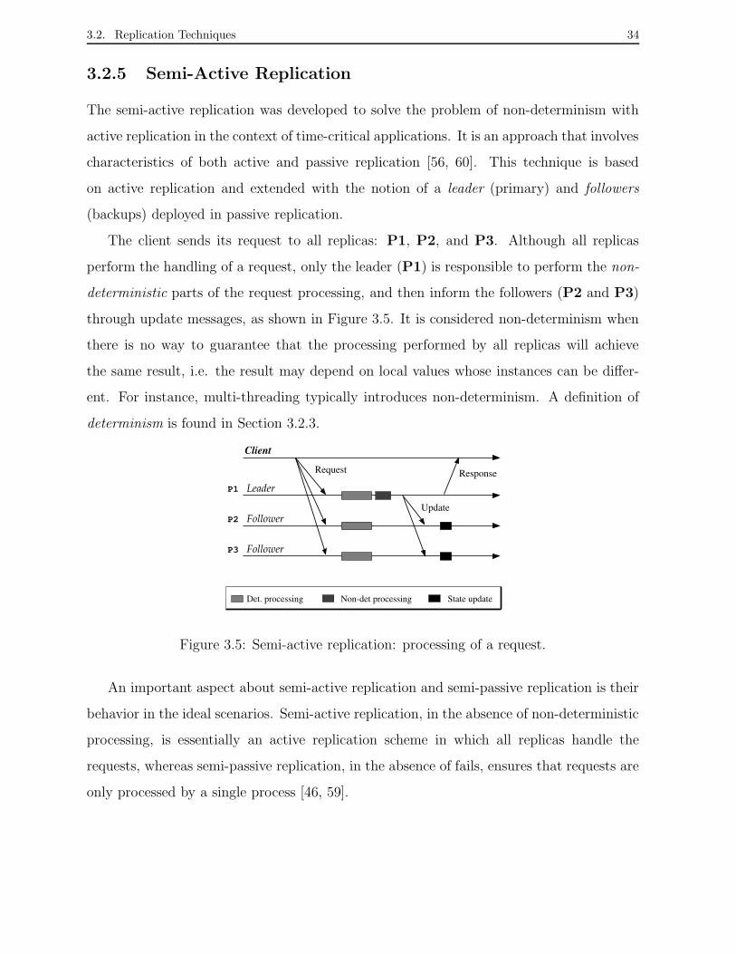
3.2. Replication Techniques 34
3.2.5 Semi-Active Replication
The semi-active replication was developed to solve the problem of non-determinism with
active replication in the context of time-critical applications. It is an approach that involves
characteristics of both active and passive replication [56, 60]. This technique is based
on active replication and extended with the notion of a leader (primary) and followers
(backups) deployed in passive replication.
The client sends its request to all replicas: P1, P2, and P3. Although all replicas
perform the handling of a request, only the leader (P1) is responsible to perform the non-
deterministic parts of the request processing, and then inform the followers (P2 and P3)
through update messages, as shown in Figure 3.5. It is considered non-determinism when
there is no way to guarantee that the processing performed by all replicas will achieve
the same result, i.e. the result may depend on local values whose instances can be differ-
ent. For instance, multi-threading typically introduces non-determinism. A definition of
determinism is found in Section 3.2.3.
P1
P2
P3
Client
Leader
Follower
Follower
Request
Update
Response
Det. processing State updateNon-det processing
Figure 3.5: Semi-active replication: processing of a request.
An important aspect about semi-active replication and semi-passive replication is their
behavior in the ideal scenarios. Semi-active replication, in the absence of non-deterministic
processing, is essentially an active replication scheme in which all replicas handle the
requests, whereas semi-passive replication, in the absence of fails, ensures that requests are
only processed by a single process [46, 59].

3.3. Group Communication 35
3.3 Group Communication
Developing distributed applications is a difficult task, because of the complexity of the
applications themselves and of the distributed settings prone to failure in which such
applications are often performed. Reliable distributed applications must ensure that its
services are provided even when failures occur. The process group abstraction is a possible
approach for constructing reliable applications [61]. This approach consists of structuring
the application into cooperating groups of processes that communicate using a reliable
multicast service. Reliable multicast services ensure that all messages sent to the group
are delivered to each group member that is not faulty. Group membership is a service
responsible for managing groups of processes, i.e. it maintains consistent information
about which members are functioning and which have failed at any moment. In order to
do this, a membership service reports failures, recoveries or joining members, indicating
changes into the membership [62, 63]. A group communication system typically provides
reliable group multicast and membership service.
Group communication systems introduce the process group abstraction. They are po-
werful tools for the development of fault-tolerant distributed applications. In fact, a group
communication system encapsulates certain solutions to fundamental problems that arise
in the development of reliable systems, providing programmers with a simple distributed
programming abstraction. Several group communication systems have been implemented
and are available, such as Transis [64], Horus [20] and Ensemble [21]. Ensemble is a group
communication toolkit that allows the development of fault-tolerant complex distributed
applications. It provides a library of protocols which handles issues such as re-liably send-
ing and receiving messages, transferring process states, implementing security, detecting
failures and managing system reconfiguration.
The group abstraction is an adequate framework for providing reliable multicast prim-
itives required to implement replication in distributed systems. The following section de-
scribes the use of the group abstraction as an alternative for building dependable network
management systems.

3.4. Passive Replication Applied to Managed Objects 36
3.4 Passive Replication Applied to Managed Objects
Replication techniques such as active replication have already been previously applied to
network management systems in order to increase their dependability [29]. However, con-
sidering the distributed nature of current network management systems and requirements
such as non-deterministic processing of the requests and low response time, we argue that
a variation of passive replication is the most adequate technique to perform the task of
replicating managed objects [11].
Passive replication can be extended in order to be applied to a management system.
Consider a simple management system composed of a collection of agents where each agent
typically keeps information about a particular managed device at its MIB (Management
Information Base). These agents could be extended to send their information to other
agents and in addition to keep information coming from other agents in the system. In
this way, a set of agents could be seen as agent group that supports a replication service
of management information.
query
Group
query
queryclient
query
query
query
Update
Update
(A)
client
agent 2
Update agent 4
agent 3
primary
agent 1
backup
backup
backup
manager
manager
query
query
query
Groupclient
query
query
query
client Update
Update
Update
(B)
primary
agent 1
agent 3
agent 2
agent 4
backup
backup
backup
manager
manager
Figure 3.6: Passive replication: agents playing as primary and backup.
In order to achieve passive replication functionality in a group of agents, each agent
must play as primary and backup at the same time. The primary role enables an agent
to multicast its objects to other agents, whereas the backup role enables an agent to keep
objects sent by other agents [10]. Thus, as Figure 3.6 shows, an agent is a primary for its
own managed objects and replicates them in other group members (A); at the same time,
3.5. Conclusion 37
it can also be a backup of other agents, i.e. keeping local replicas of managed objects of
other group members (B).
A client can query any group agent through a query request for accessing as local objects
the replicated objects, as shown in Figure 3.6. However, only the source agent of a MIB
can send update requests to other agents for replicating and updating its managed objects.
Systems which implement passive replication typically only allow access to the primary
copy. However, in network management systems, management entities that keep managed
objects can frequently be accessed by manager applications. Hence, such systems can also
allow queries to any network entity that keeps copies of replicated information. We define
this extension of the passive replication for replicating managed objects in which queries
can be done to any member of an agent group as passive replication with read operations
on backup agents.
3.5 Conclusion
In this chapter, we presented concepts on failure models, replication techniques, and group
abstraction which allow the construction of reliable distributed systems.
The description of main failure models found in distributed computing systems was
presented. Replication techniques allow the development of reliable systems through the
redundancy of theirs components. We presented an overview of the replication techniques
passive, coordinator-cohort, active, semi-passive, and semi-active that can be used to repli-
cate a service in distributed systems. The study discussed the differences and similarities
of replication techniques taking into account a client-server model.
The process group abstraction is an approach that have been used to building reliable
applications in settings prone to failure. Typically, this approach structures a distributed
application in cooperating groups of processes that communicate using a reliable multicast
service. Thus, if a process fails, other processes can execute its task, for example. In
general, such approach enables that a distributed application can tolerante several kinds
of failures.

3.5. Conclusion 38
The complexity and the distributed nature of current network management systems in-
troduce ideal characteristics to apply both the group abstraction and the passive replication
technique for supporting the construction of group-based reliable network management sys-
tems. Thus, management information replicated among the network management entities
could still be accessed even if certain network entities are faulty.
Chapter 4
Management by Replication:
Specification
It is essential that a network management system works correctly during occurrences of
network faults. Data replication is an attractive mechanism for building fault-tolerant
systems since it simultaneously increases the availability of a system. Hence, the use
of data replication in a distributed network management system provides the means for
getting management data from a faulty network element.
This chapter presents the requirements and the specification of an agent clustering ar-
chitecture for building fault-tolerant network management systems. Section 4.1 describes
the requirements of the agent clustering architecture for supporting the replication of man-
aged objects. Section 4.2 presents the model of the agent clustering architecture as well
as assumptions about the failure model. Section 4.3 presents the issues and properties of
the architecture in order to keep the consistency of the replicated objects even in failure
situations. Section 4.4 introduces the agent clustering architecture structured in three lay-
ers based on the SNMP framework. Furthermore, we present an example of usage of the
architecture.
39
4.1. Requirements of the System 40
4.1 Requirements of the System
There is a number of possibilities to implement redundancy in a distributed system. In par-
ticular, the available resources of communication and processing in a network environment
are factors that must be taken into account at the moment of defining the redundancy
strategy to be applied. Moreover, those resources are essential in failure situations, in
which the network operation is affected and such resources are reduced.
The cluster abstraction employed in the agent clustering architecture takes into account
the issue of resource consumption needed for supporting managed objects replication and
hence allowing the building of practical network monitoring systems.
The following functional requirements are identified for the MO’s replication system
in order to allocate the minimal amount of network resources as well as to guarantee the
distribution of replicated objects in various places on the network.
• Flexibility: configuration of several collections of managed objects from clusters of
network elements to be replicated; which network elements are members of a cluster;
and in which network elements those managed objects must be replicated.
• Availability: copies of values of managed objects may be kept in specific network
elements in the system. Thus, while there is at least an accessible copy of managed
objects, i.e. a fault-free network element, the access to values of such objects is
guaranteed.
• Consistency: values of managed objects, which are replicated among various network
management entities, must be consistent with the original values.
• Scalability: the increase in the number of agents or managed objects to be replicated
in the system requires the allocation of more network resources. In order to enable the
operation of replication and reduce the network resource consumption, the clustering
architecture allows both the creation and redefinition of new agents clusters.

4.2. Specification 41
In the following, we describe the architecture of agent clustering for managed objects
replication.
4.2 Specification
In this section we present the specification of the agent clustering architecture for replicat-
ing managed objects as well as assumptions about the failure model and the communication
model.
The system model consists of multiple network elements, called nodes, connected by a
network. The nodes only experience the fail-stop failure model, i.e. a node either operates
correctly or not at all [51]. We assume that no network partitions occur and that the
system is synchronous, hence it is possible to estimate the time required for both message
transmission and processing. Although the considered failure model as well as the kind of
network partition are not well adequate to all kinds of networks, we are considering those
assumptions in our model since they are adequate to local area networks. Such assumptions
will be studied in other kinds of network such as WAN (Wide Area Network) and MAN
(Metropolitan Area Network) later in order to check if they attend to the requirements
of the system. The fail-stop failure model, according to the kind of network, can affect
requirements such as the scalability of the system model.
In the system model, a given node contains the manager application and each one of
the other nodes contains an agent application. We consider that the manager application
is similar to any manager based on the manager-agent paradigm, and furthermore it never
fails and has the ability to detect a faulty node. In addition, we consider that certain agents
can be extended to play the cluster manager role. A cluster manager is an agent which
can collect and replicate information to other cluster managers. Typically, management
information is kept in variables termed objects. In particular, ordinary agents only keep
local information about nodes where they are hosted, whereas a cluster manager can keep
replicated information from other agent applications.
The following nomenclature is used throughout this section and next section to iden-
4.2. Specification 42
tify the system entities. Entities can introduce one or two subscripts. Entities with one
subscript are used to indicate an element in a set. Let 2i be an entity. The subscript i
refers to the i-th element of 2. For example, value qi. Entities with two subscripts are
used to indicate an element whose value is a copy of another element value. Let 2i,j be an
entity. The subscript i refers to the i-the element of 2 and the subscript j refers to a copy
of element 2i kept in element 2i,j. For example, in notation qi,j, the value of element qi is
copied in element qi,j, in this case qi and qi,j are sets.
Let A = {a1, a2, a3, . . . , an} be the set of all agents in the system model. Let O =
{o1, o2, o3, . . . , om} be the set of all objects at the agents. Let L = {l1, l2, l3, . . . , lk} be the
set of all cluster managers, where L ⊆ A. A cluster manager is an agent defined by the
manager in order to carry out the task of monitoring and replicating managed objects.
4.2.1 Cluster
Clusters are logical abstractions in the system that the manager defines with the purpose
of replicating information kept by a group of agents. Let C = {c1, c2, . . . , ck} denote the
set of all possible clusters defined by the manager.
A cluster ci is a four-tuple (li, Gi, Ri, Pi), where
• li is an agent that denotes the manager role, which monitors and replicates managed
objects, li ∈ L. Furthermore, the relation among L and C is symmetric;
• Gi is a set of agents monitored by the cluster manager li, where Gi ⊆ A;
• Ri is a set of managed objects to be monitored by the cluster manager li, where
Ri ⊆ 2O;
• Pi is a set of the peer clusters, where Pi ⊆ C. Peer clusters are named other clusters
that receive and keep replicated information sent by a given cluster. The communica-
tion among clusters for replicating information occurs through their cluster managers.
4.2. Specification 43
4.2.2 Cluster Manager Operation
As mentioned earlier, we assume the fail-stop model and consider the existence of a com-
munication subsystem connecting cluster managers in order to provide primitives to broad-
cast messages. In addition, we consider that the communication among cluster managers
requires group services, such as membership and reliable multicast, for supporting consis-
tency of replicated information. One possible solution for the achievement of those kinds of
services, besides implementing them into the system, is the usage of group communication
protocols [20, 21, 64].
In order to execute the monitoring and replication task of a cluster, and also receive data
replicated from the other clusters, the following three communication operations below are
defined for the cluster manager of cluster ci:
• query(a,o): is the operation periodically issued by cluster manager li in order to
query a managed object <o> of an agent <a>;
• replicate(m): is the operation periodically issued by cluster manager li in order to
send a message to their peer cluster managers. A message <m> contains the value
of a replicated object;
• receive(m): is the operation periodically issued by cluster manager li when receiving
a message sent by other cluster manager. A message <m> contains the value of a
replicated object.
The first operation corresponds to a communication primitive normally issued by the
manager for querying ordinary agents in a network management system based on the
manager-agent paradigm. Let Qi = {q1, q2, q3, ..., qn} denote the set of queries that a
cluster manager li should periodically issue to an agent a ∈ Gi.
qi : A×O −→ O ∪ ∅
(a, o) 7−→ qi(a, o) =
∅ : if a has failed
6= ∅ : if a is fault-free
Thus, a query qi corresponds to a communication operation denoted by query(a,o)
in order to collect information of a monitored object. The query result will always be

4.2. Specification 44
successful and return a value when agent a is fault-free. On the other hand, if the agent
has failed, the query result will not return any value.
The second and third operations correspond to group communication primitives de-
ployed by cluster managers in order to communicate with their peer clusters. Note that
cluster managers only communicate with fault-free peer clusters. Thus, it is required a
failure detection mechanism. Let F thus denote an underlying failure detection function
used by cluster managers as a service of group control. This function is defined as follows:
F : L −→ {0, 1}
ci 7−→
0 : if ci has failed
1 : if ci is fault-free
Thus,
{∀ci, cj ∈ C | cj ∈ Pi, F (cj) = 1} =⇒ P1 and P2
where
• P1 means that cluster cj receives any message sent by cluster ci;
• P2 means that cluster cj receives messages in the same order sent by cluster ci.
In summary, a cluster manager introduces two types of communication to carry out the
object replication: the cluster manager - agent communication and the cluster manager
- cluster manager communication. The former enables a cluster manager to monitor the
agent members, and the latter enables a cluster manager to replicate their objects at the
peer clusters.
4.2.3 Replicated Information
A replica represents the copy of values of a set of objects of a group of agents monitored
by a cluster manager. Let ci = (li, Gi, Ri, Pi) be a cluster and let ri,j = {(o, a) | o ∈ Ri
and a ∈ Gi} denote a replica kept by the cluster manager of cluster cj. Hence, a pair (o, a)
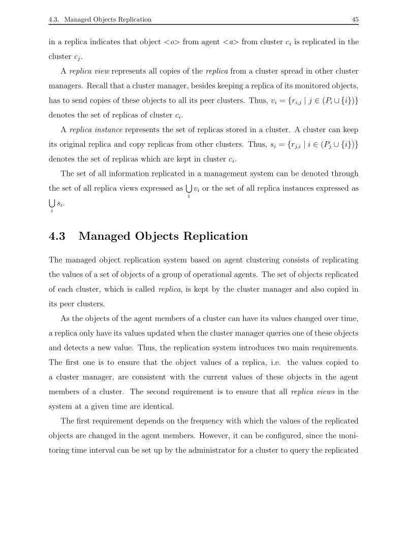
4.3. Managed Objects Replication 45
in a replica indicates that object <o> from agent <a> from cluster ci is replicated in the
cluster cj.
A replica view represents all copies of the replica from a cluster spread in other cluster
managers. Recall that a cluster manager, besides keeping a replica of its monitored objects,
has to send copies of these objects to all its peer clusters. Thus, vi = {ri,j | j ∈ (Pi ∪ {i})}
denotes the set of replicas of cluster ci.
A replica instance represents the set of replicas stored in a cluster. A cluster can keep
its original replica and copy replicas from other clusters. Thus, si = {rj,i | i ∈ (Pj ∪ {i})}
denotes the set of replicas which are kept in cluster ci.
The set of all information replicated in a management system can be denoted through
the set of all replica views expressed as⋃
i
vi or the set of all replica instances expressed as⋃
i
si.
4.3 Managed Objects Replication
The managed object replication system based on agent clustering consists of replicating
the values of a set of objects of a group of operational agents. The set of objects replicated
of each cluster, which is called replica, is kept by the cluster manager and also copied in
its peer clusters.
As the objects of the agent members of a cluster can have its values changed over time,
a replica only have its values updated when the cluster manager queries one of these objects
and detects a new value. Thus, the replication system introduces two main requirements.
The first one is to ensure that the object values of a replica, i.e. the values copied to
a cluster manager, are consistent with the current values of these objects in the agent
members of a cluster. The second requirement is to ensure that all replica views in the
system at a given time are identical.
The first requirement depends on the frequency with which the values of the replicated
objects are changed in the agent members. However, it can be configured, since the moni-
toring time interval can be set up by the administrator for a cluster to query the replicated
4.3. Managed Objects Replication 46
objects. Since the main goal of the replication system is to ensure access to the last in-
formation of network elements, the system must include mechanisms to guarantee that
the replica views are consistent. Group services employed to among cluster managers can
guarantee the second requirement. Thus, when the agent members or the cluster managers
are faulty, their data is still available elsewhere.
MO’s Replication Properties
The object replication system must obey several properties in order to keep its data consis-
tent. Particularly, the safety and liveness properties are important because they guarantee
the correct operation of the replication system. In the following, we define those properties
in term of clusters and replicas.
We consider that when a group of clusters is created, every cluster ci makes in its
cluster manager a replica ri = {(o1, a1, ), (o2, a1), (o1, a2), (o2, a2), ..., (om, an)}. For each
pair (oj, ak) ∈ ri, oj denotes the value of an object from agent ak which is both monitored
and replicated in cluster ci. Furthermore, the cluster manager of cluster ci distributes
copies of replica ri to the peer clusters of cluster ci. Once replica ri is stored at the cluster
manager of cluster ci, any change in the values of the objects detected by the cluster
manager will result in an update of the replica ri. Hence, the cluster manager of cluster ci
must also multicast such values changes to its peer clusters in order to guarantee that all
copies of replica ri are updated, and thus replica view vi is always kept consistent.
Let C = {c1, c2, c3, ..., cn} be a set of clusters. The replicas kept at the cluster managers
must adhere to the properties below:
Safety Properties
• Validity 01: if cluster cj ∈ C keeps a copy of replica ri, i.e. cj contains ri,j, then
cj ∈ Pi.
• Validity 02: if cluster cj ∈ Pi and it does not receive updates on its copy of replica
ri, then cj is faulty.

4.4. An Agent Clustering Architecture Using SNMP 47
• Agreement: if cluster cj ∈ Pi receives an update value on replica ri,j and cluster
ck ∈ Pi also receives an update value on replica ri,k, then ri,j = ri,k.
Validity 01 property states that only the peer clusters of a cluster keep a copy of its
replica. Validity 02 property states that changes on the local replica of a cluster will be
multicast for all peer clusters since they are not faulty. The Agreement property states
that any update modifying a replica copy delivered to a peer cluster will eventually be
delivered to all peer clusters.
Liveness Property
• Termination: if the cluster manager of cluster ci does not fail, then the objects of its
agent members will continue to be replicated, as well as copies of the replicas from
other clusters will be kept by the cluster manager of ci.
In order to ensure safety and liveness properties to the MO’s replication system, even in
failure situations of cluster managers, group services, such as reliable multicast and group
membership, must be supported by the system [65, 66, 67].
In this section we have identified and described the properties of the agent clustering
architecture for replicating managed objects. Next, we present the architecture of agent
clustering based on the SNMP framework.
4.4 An Agent Clustering Architecture Using SNMP
The Simple Network Management Protocol version 3 (SNMPv3) is the Internet standard
management architecture [4], as seen in Chapter 2. Thus, given its popularity worldwide,
we have deployed the SNMPv3 framework in order to define the agent clustering architec-
ture for replicating managed objects.
An SNMPv3 system is composed of management entities that communicate using the
management protocol. The SNMP architecture defines a Management Information Base
(MIB) as a collection of related management objects that are kept at the agents in order
to allow management applications to monitor and control the managed elements. SNMP

4.4. An Agent Clustering Architecture Using SNMP 48
entities have traditionally been called managers and agents. A managed network element
contains an agent, which is a management entity that has access to management instru-
mentation. Managers are collections of user-level applications, which provide services such
as performance evaluation, fault diagnosis, and accounting, among others. Each manage-
ment system has at least one Network Management Station (NMS), which runs at least
one manager entity [18].
Distributed network management is widely recognized as a requirement for dealing
with large, complex, and dynamic networks [6, 43]. The distributed management entities
assume roles like executing scripts [68], monitoring events [69], scheduling actions [70] or
reporting alarms [71], among others. Thus, three-tier architectures have become popular for
distributed management, in which mid-level distributed management entities are included
between agents in the bottom level and managers in the top level.
Considering both the SNMP architecture and the distributed network management
paradigm mentioned above, the proposed agent clustering architecture expands SNMP
architecture by adding modules that provide functionality for fault tolerance through a
logical way of dividing the network elements in clusters and replicating managed objects.
The SNMP agent clustering architecture for replicating managed objects is structured
in three layers, as shown in Figure 4.1. The three layers are called the manager layer, the
cluster layer, and the cluster member layer, respectively, and are described below.
• The manager layer is composed by managers, i.e. management applications, which
define clusters as well as the relationship among cluster managers.
• The cluster layer is composed by the management entities playing as cluster mana-
gers. Each cluster manager is an ordinary agent that has the task of periodically
monitoring a subset of managed objects of its cluster members and replicating those
objects in other cluster managers.
• The cluster member layer is composed by all cluster members, i.e. network manage-
ment entities which have their managed objects monitored and replicated by a cluster
manager.
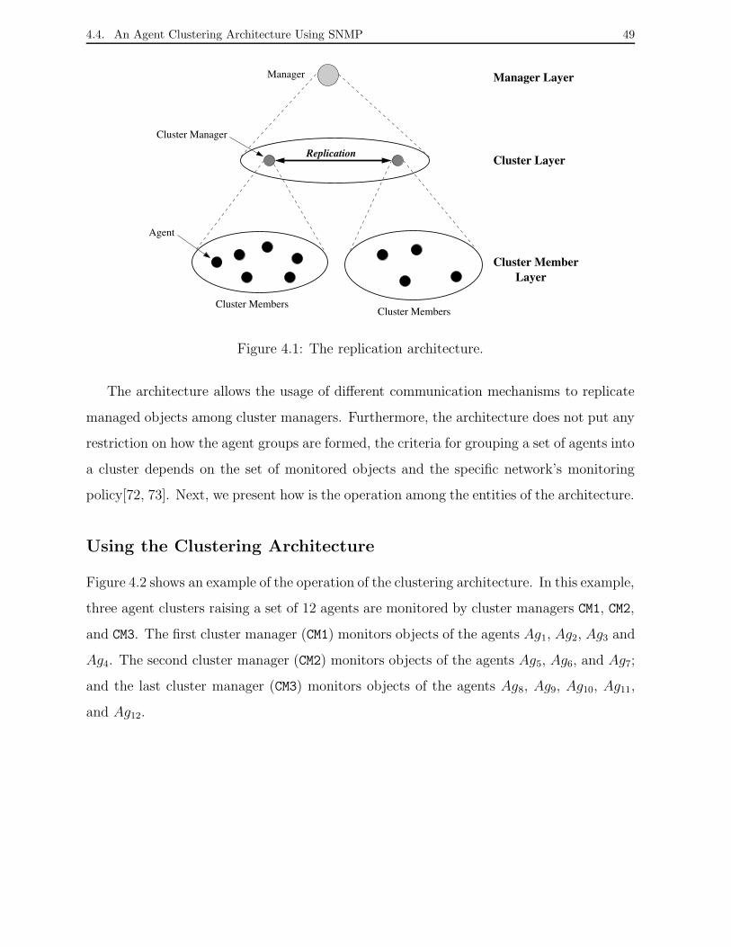
4.4. An Agent Clustering Architecture Using SNMP 49
Replication
Cluster Members
Cluster Manager
Agent
Manager Manager Layer
Cluster Layer
Cluster MemberLayer
Cluster Members
Figure 4.1: The replication architecture.
The architecture allows the usage of different communication mechanisms to replicate
managed objects among cluster managers. Furthermore, the architecture does not put any
restriction on how the agent groups are formed, the criteria for grouping a set of agents into
a cluster depends on the set of monitored objects and the specific network’s monitoring
policy[72, 73]. Next, we present how is the operation among the entities of the architecture.
Using the Clustering Architecture
Figure 4.2 shows an example of the operation of the clustering architecture. In this example,
three agent clusters raising a set of 12 agents are monitored by cluster managers CM1, CM2,
and CM3. The first cluster manager (CM1) monitors objects of the agents Ag1, Ag2, Ag3 and
Ag4. The second cluster manager (CM2) monitors objects of the agents Ag5, Ag6, and Ag7;
and the last cluster manager (CM3) monitors objects of the agents Ag8, Ag9, Ag10, Ag11,
and Ag12.

4.4. An Agent Clustering Architecture Using SNMP 50
Cluster 1 Cluster 3
Cluster 2
CM2CM3CM1
Ag1 Ag2
Ag3 Ag4
Ag6
Ag7
Ag8
Ag9
Ag10Ag12
Ag11
Agent MemberAg Cluster ManagerCM Managed Objects
Ag5
Figure 4.2: The operation of the clustering architecture.
Figure 4.2 focuses particularly on the operation of the CM1, and its operation with
other two cluster managers. Thus, CM1 periodically monitors the objects of its agents,
keeps one copy of those objects, and next replicates them at its two peer cluster managers
(CM2 and CM3), as shown by the solid and dotted lines respectively in the figure. At the
same time, CM1 will also receive replicated objects from CM2 and CM3 in which it has been
defined as peer cluster. Considering the passive replication approach employed, CM1 is the
leader for all replicated objects of its agent cluster; the same functioning occurs in CM2 and
CM3.
Manager
Cluster 1
Ag1 Ag2
Ag3 Ag4
CM1 CM3CM2
(3) (4)
(2)
(1)
Figure 4.3: Querying replicas by the general manager
4.5. Conclusion 51
The architecture allows the manager to have many options to query values of manage-
ment objects from a given agent. Taking into account the example architecture defined
above, Figure 4.3 illustrates the alternatives that the manager can execute in order to
query object values monitored by the cluster manager CM1. In the example, it is assumed
that all cluster managers contain replicas of the objects monitored by all clusters. First,
the manager can make a query to CM1, (1) in the figure. If the query is not successful, i.e.
no reply arrives (2), the manager still has the option to obtain that information through
the peer clusters. The manager then can make a query to CM2 and obtain the replicated
objects from CM1 (3 and 4).
We have described, through of this scenery example, the operation of the architecture
and have shown its capacity to deal with faulty network elements.
4.5 Conclusion
In this chapter, we introduced an architecture based on agent clustering for supporting the
replication of managed objects. The architecture took into account fundamental charac-
teristics for current distributed systems such as the flexibility and scalability requirements.
The architecture describes the structure of the construction of logical clusters, the com-
munication primitives, which allows the cluster operation, and how the relationship among
clusters occurs. Furthermore, the several collections of data replicated by management
entities were specified. Particularly, we defined as replica the collection of objects both
monitored and replicated by a cluster manager. Copies of a replica spread in other clusters
of a management system are defined as replica view, and copies of replicas kept in a cluster
are defined as replica instance. Group services must guarantee the consistency among the
copies of a replica. Hence, we introduced the safety and liveness properties that ensure the
correct operation of the replication system.
Finally, we described a three-layer agent cluster architecture taking into account the
SNMP framework, where the upper layer corresponds to the manager application that
defines management clusters and their relationships, and the middle layer corresponds to

4.5. Conclusion 52
management entities called cluster managers, which monitor a given set of agents.

Chapter 5
An SNMP Framework for Object
Replication in Agent Clusters
In this chapter, we describe the SNMP agent clustering framework specified as a MIB.
This framework introduces the management objects defined for supporting managed object
replication based on the clustering architecture. Section 5.1 presents the MIB that defines
the framework. Section 5.2 describes how to define SNMP management clusters and their
relationships. Section 5.3 presents the values required to make traditional SNMP agents in
cluster managers. Section 5.4 describes the parameters that define a subset of replicated
objects in a given cluster. Section 5.5 describes the parameters required to define the peer
clusters of a given cluster. Section 5.6 describes how values of the replicated objects are
kept.
5.1 The MIB for Replicating MO’s
In this section, we present an SNMP agent clustering framework that supports passive
replication of management objects. The framework is defined as a MIB called Replic-MIB
which allows the definition and usage of management clusters, as well as the replication
operation among clusters. The MIB is divided in two groups: clusterDefinition and
53

5.1. The MIB for Replicating MO’s 54
clusterReplica, as shown in Figure 5.1 and described in the following.
Throughout this chapter, we will often refer to a manager application only as manager,
and a cluster of agents only as cluster. Furthermore, it is important to keep in mind that
a cluster manager is an agent which plays a manager role from a cluster of agents in order
to replicate managed objects.
clusterDefinition
replicObjects
replicaTable
clusterReplication
repObjectTable
memberTable
clusterTable
peerTable
Figure 5.1: Replic-MIB: basic structure.
The clusterDefinition group consists of four tables: clusterTable, memberTable,
repObjectTable, and peerTable. Those tables are deployed at management application
and agents in order to define and build agent clusters (clusters). Table clusterTable
contains the whole definition of all clusters, and it is kept only at the manager. Entries of
table clusterTable defining a cluster include the definition of its cluster members (agents
to be monitored), the specification of managed objects to be replicated, and the definition
of peer clusters. In this way, the administrator can automatically to build an given cluster
from a manager.
Tables memberTable, repObjectTable, and peerTable are built by the manager into
the agents defined as cluster managers. Table memberTable contains information that
specifies each member in the cluster. Table repObjectTable contains the definition of
each management object to be replicated. Table peerTable defines the cluster managers
that play as peer clusters keeping copies of the replicated management objects.
The clusterReplication group consists of a single core table called replicaTable.
This table is automatically built into the cluster managers, and keeps replicated managed
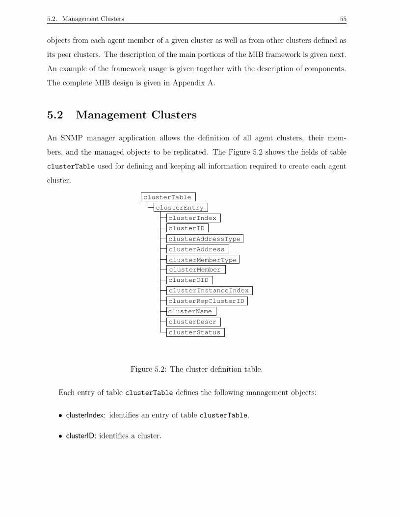
5.2. Management Clusters 55
objects from each agent member of a given cluster as well as from other clusters defined as
its peer clusters. The description of the main portions of the MIB framework is given next.
An example of the framework usage is given together with the description of components.
The complete MIB design is given in Appendix A.
5.2 Management Clusters
An SNMP manager application allows the definition of all agent clusters, their mem-
bers, and the managed objects to be replicated. The Figure 5.2 shows the fields of table
clusterTable used for defining and keeping all information required to create each agent
cluster.
clusterID
clusterTable
clusterEntry
clusterIndex
clusterAddress
clusterMember
clusterOID
clusterInstanceIndex
clusterRepClusterID
clusterName
clusterDescr
clusterStatus
clusterAddressType
clusterMemberType
Figure 5.2: The cluster definition table.
Each entry of table clusterTable defines the following management objects:
• clusterIndex: identifies an entry of table clusterTable.
• clusterID: identifies a cluster.

5.2. Management Clusters 56
• clusterAddressType: describes the type of address in clusterAddress. For example,
IPv4 or IPv6.
• clusterAddress: identifies the cluster manager, i.e. the SNMP entity that monitors a
set of agents.
• clusterMemberType: defines the type of address of each member of a given cluster
(clusterMember). For example, IPv4 or IPv6.
• clusterMember: defines the address of each member of a given cluster.
• clusterOID: defines the instance OID (the ASN.1 object identifier) of a managed object
which is replicated.
• clusterInstanceIndex: defines the instance index of a managed object which is repli-
cated.
• clusterRepClusterID: (RepCID) keeps the identifier of the peer clusters.
• clusterName: keeps information about the administrator responsible for the cluster.
• clusterDescr: describes the purpose of the cluster.
• clusterStatus: indicates the status of the cluster.
Next, an example of table clusterTable is given together with its description.
The Framework Usage: A clusterTable Example
Table 5.1 illustrates the complete clusterTable example of an SNMP management
system that defines two clusters whose cluster managers are identified as Ci and Cj. The
type of address in each cluster manager is ipv4(1), and their IP addresses are 10.0.0.1 and
10.0.0.2, respectively.

5.2. Management Clusters 57
Index ID Address Address Member Mem- OID Instance Rep Name Descr Status
Type Type ber Index CID
1 Ci ipv4(1) 10.0.0.1 ipv4(1) Mb1 ifInOctets 1 Cj John example active(1)
2 Ci ipv4(1) 10.0.0.1 ipv4(1) Mb1 ifInOctets 2 Cj John example active(1)
3 Ci ipv4(1) 10.0.0.1 ipv4(1) Mb2 ifInOctets 1 Cj John example active(1)
4 Ci ipv4(1) 10.0.0.1 ipv4(1) Mb2 ifInOctets 2 Cj John example active(1)
5 Cj ipv4(1) 10.0.0.2 ipv4(1) Mb3 ifInOctets 1 Ci John example active(1)
6 Cj ipv4(1) 10.0.0.2 ipv4(1) Mb4 ifInOctets 1 Ci John example active(1)
Table 5.1: An example cluster table as defined at the manager application level.
The cluster monitored by cluster manager Ci contains two agent members identified
(labelled) as Mb1 and Mb2 in the table in place of their IP addresses, 10.0.0.3 and 10.0.0.4,
respectively. The type of address in Mb1 and Mb2 is ipv4(1). Ci monitors the instance
indexes 1 and 2 of the ifInOctets OID from all members of its cluster (Mb1 and Mb2).
Those managed objects are kept replicated in Ci and in Cj, which is defined as its peer
cluster.
The cluster monitored by cluster manager Cj contains two agent members identified
(labelled) as Mb3 and Mb4 in the table in place of their IP addresses, 10.0.0.5 and 10.0.0.6,
respectively. The type of address in Mb3 and Mb4 is ipv4(1). Cj monitors instance index
1 of the ifInOctets OID from all members of its cluster (Mb3 and Mb4). This managed
object is kept replicated in Cj and in Ci, which is defined as its peer cluster.
The administrator responsible for defining each agent cluster is known as John. The
purpose in defining two clusters is to describe a cluster table example. The status of each
table entry is active(1), i.e. all information is complete.
The management object example defined to be replicated, ifInOctet, keeps the number
of octets that has arrived through a given network interface [18]. It is defined in MIB-2
(see Chapter 2). In fact, Ci as well as Cj could be monitoring different managed object.
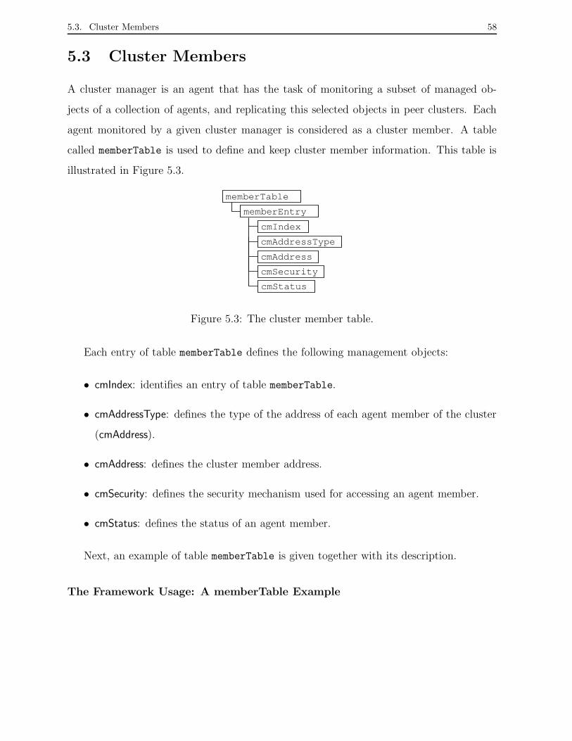
5.3. Cluster Members 58
5.3 Cluster Members
A cluster manager is an agent that has the task of monitoring a subset of managed ob-
jects of a collection of agents, and replicating this selected objects in peer clusters. Each
agent monitored by a given cluster manager is considered as a cluster member. A table
called memberTable is used to define and keep cluster member information. This table is
illustrated in Figure 5.3.
memberTable
memberEntry
cmIndex
cmAddress
cmSecurity
cmStatus
cmAddressType
Figure 5.3: The cluster member table.
Each entry of table memberTable defines the following management objects:
• cmIndex: identifies an entry of table memberTable.
• cmAddressType: defines the type of the address of each agent member of the cluster
(cmAddress).
• cmAddress: defines the cluster member address.
• cmSecurity: defines the security mechanism used for accessing an agent member.
• cmStatus: defines the status of an agent member.
Next, an example of table memberTable is given together with its description.
The Framework Usage: A memberTable Example

5.4. Replicated Objects 59
Table 5.2 illustrates the complete memberTable example kept in the cluster manager Ci.
This cluster manager defines two agent members (Mb1 and Mb2), which have IP addresses
10.0.0.3 and 10.0.0.4, respectively. The type of address in Mb1 and Mb2 is ipv4(1). Fur-
thermore, each agent member employs community as the security mechanism. The status
of each agent member in the cluster is active(1), i.e. currently they are monitored by Ci.
Index Address Type Address Security Status
1 ipv4(1) 10.0.0.3 (Mb1) community active(1)
2 ipv4(1) 10.0.0.4 (Mb2) community active(1)
Table 5.2: An example member table in cluster Ci.
The cluster manager Cj also keeps a table memberTable defining its cluster members.
5.4 Replicated Objects
Besides specifying the members of a cluster, it is also necessary to define which objects
are replicated in the cluster manager. Table repObjectTable, illustrated in Figure 5.4, is
used to determine which objects are replicated in a given cluster.
roOID
repObjectTable
repObjectEntry
roIndex
roInstanceIndex
roInterval
roState
roStatus
Figure 5.4: The replicated object table.
Each entry of table repObjectTable defines the following management objects:
• roIndex: identifies an entry of table repObjectTable.
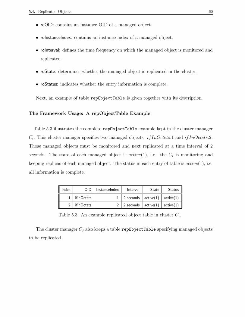
5.4. Replicated Objects 60
• roOID: contains an instance OID of a managed object.
• roInstanceIndex: contains an instance index of a managed object.
• roInterval: defines the time frequency on which the managed object is monitored and
replicated.
• roState: determines whether the managed object is replicated in the cluster.
• roStatus: indicates whether the entry information is complete.
Next, an example of table repObjectTable is given together with its description.
The Framework Usage: A repObjectTable Example
Table 5.3 illustrates the complete repObjectTable example kept in the cluster manager
Ci. This cluster manager specifies two managed objects: ifInOctets.1 and ifInOctets.2.
Those managed objects must be monitored and next replicated at a time interval of 2
seconds. The state of each managed object is active(1), i.e. the Ci is monitoring and
keeping replicas of each managed object. The status in each entry of table is active(1), i.e.
all information is complete.
Index OID InstanceIndex Interval State Status
1 ifInOctets 1 2 seconds active(1) active(1)
2 ifInOctets 2 2 seconds active(1) active(1)
Table 5.3: An example replicated object table in cluster Ci.
The cluster manager Cj also keeps a table repObjectTable specifying managed objects
to be replicated.
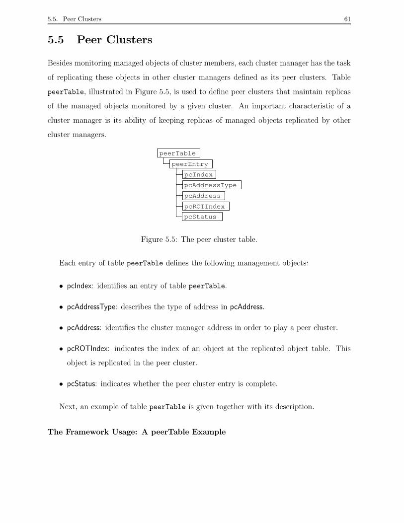
5.5. Peer Clusters 61
5.5 Peer Clusters
Besides monitoring managed objects of cluster members, each cluster manager has the task
of replicating these objects in other cluster managers defined as its peer clusters. Table
peerTable, illustrated in Figure 5.5, is used to define peer clusters that maintain replicas
of the managed objects monitored by a given cluster. An important characteristic of a
cluster manager is its ability of keeping replicas of managed objects replicated by other
cluster managers.
peerTable
peerEntry
pcIndex
pcAddress
pcROTIndex
pcStatus
pcAddressType
Figure 5.5: The peer cluster table.
Each entry of table peerTable defines the following management objects:
• pcIndex: identifies an entry of table peerTable.
• pcAddressType: describes the type of address in pcAddress.
• pcAddress: identifies the cluster manager address in order to play a peer cluster.
• pcROTIndex: indicates the index of an object at the replicated object table. This
object is replicated in the peer cluster.
• pcStatus: indicates whether the peer cluster entry is complete.
Next, an example of table peerTable is given together with its description.
The Framework Usage: A peerTable Example
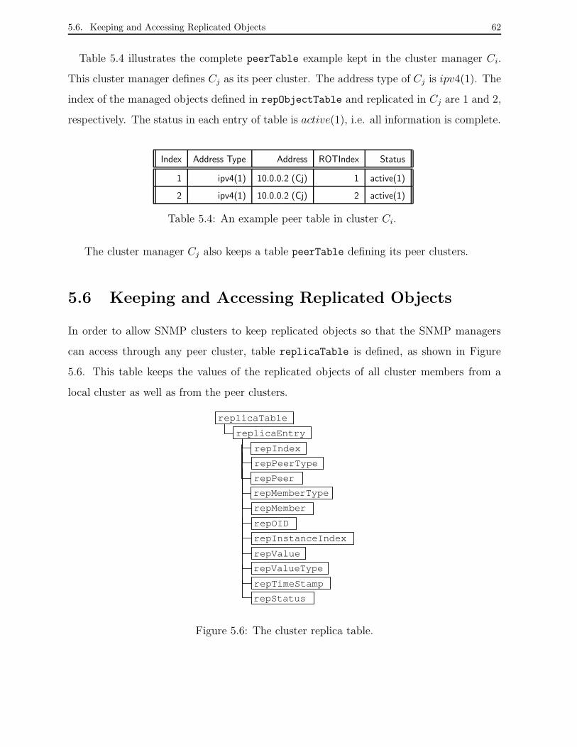
5.6. Keeping and Accessing Replicated Objects 62
Table 5.4 illustrates the complete peerTable example kept in the cluster manager Ci.
This cluster manager defines Cj as its peer cluster. The address type of Cj is ipv4(1). The
index of the managed objects defined in repObjectTable and replicated in Cj are 1 and 2,
respectively. The status in each entry of table is active(1), i.e. all information is complete.
Index Address Type Address ROTIndex Status
1 ipv4(1) 10.0.0.2 (Cj) 1 active(1)
2 ipv4(1) 10.0.0.2 (Cj) 2 active(1)
Table 5.4: An example peer table in cluster Ci.
The cluster manager Cj also keeps a table peerTable defining its peer clusters.
5.6 Keeping and Accessing Replicated Objects
In order to allow SNMP clusters to keep replicated objects so that the SNMP managers
can access through any peer cluster, table replicaTable is defined, as shown in Figure
5.6. This table keeps the values of the replicated objects of all cluster members from a
local cluster as well as from the peer clusters.
replicaTable
replicaEntry
repIndex
repPeer
repMember
repOID
repInstanceIndex
repValueType
repTimeStamp
repStatus
repPeerType
repMemberType
repValue
Figure 5.6: The cluster replica table.
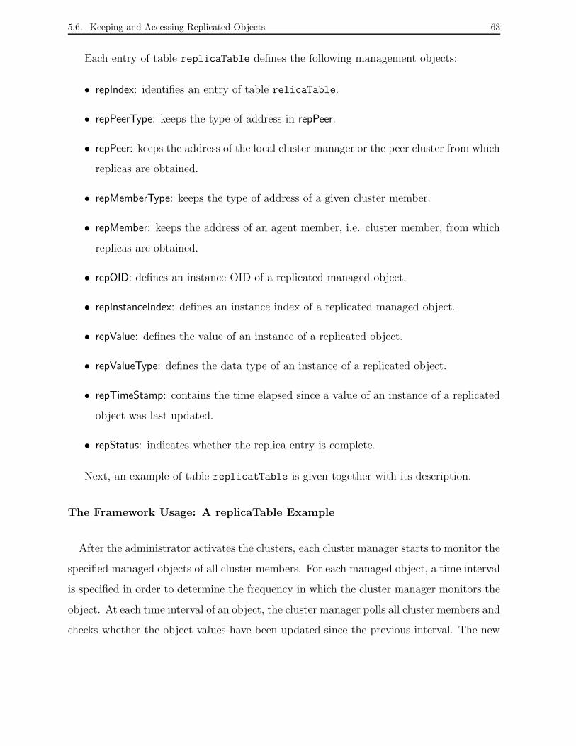
5.6. Keeping and Accessing Replicated Objects 63
Each entry of table replicaTable defines the following management objects:
• repIndex: identifies an entry of table relicaTable.
• repPeerType: keeps the type of address in repPeer.
• repPeer: keeps the address of the local cluster manager or the peer cluster from which
replicas are obtained.
• repMemberType: keeps the type of address of a given cluster member.
• repMember: keeps the address of an agent member, i.e. cluster member, from which
replicas are obtained.
• repOID: defines an instance OID of a replicated managed object.
• repInstanceIndex: defines an instance index of a replicated managed object.
• repValue: defines the value of an instance of a replicated object.
• repValueType: defines the data type of an instance of a replicated object.
• repTimeStamp: contains the time elapsed since a value of an instance of a replicated
object was last updated.
• repStatus: indicates whether the replica entry is complete.
Next, an example of table replicatTable is given together with its description.
The Framework Usage: A replicaTable Example
After the administrator activates the clusters, each cluster manager starts to monitor the
specified managed objects of all cluster members. For each managed object, a time interval
is specified in order to determine the frequency in which the cluster manager monitors the
object. At each time interval of an object, the cluster manager polls all cluster members and
checks whether the object values have been updated since the previous interval. The new
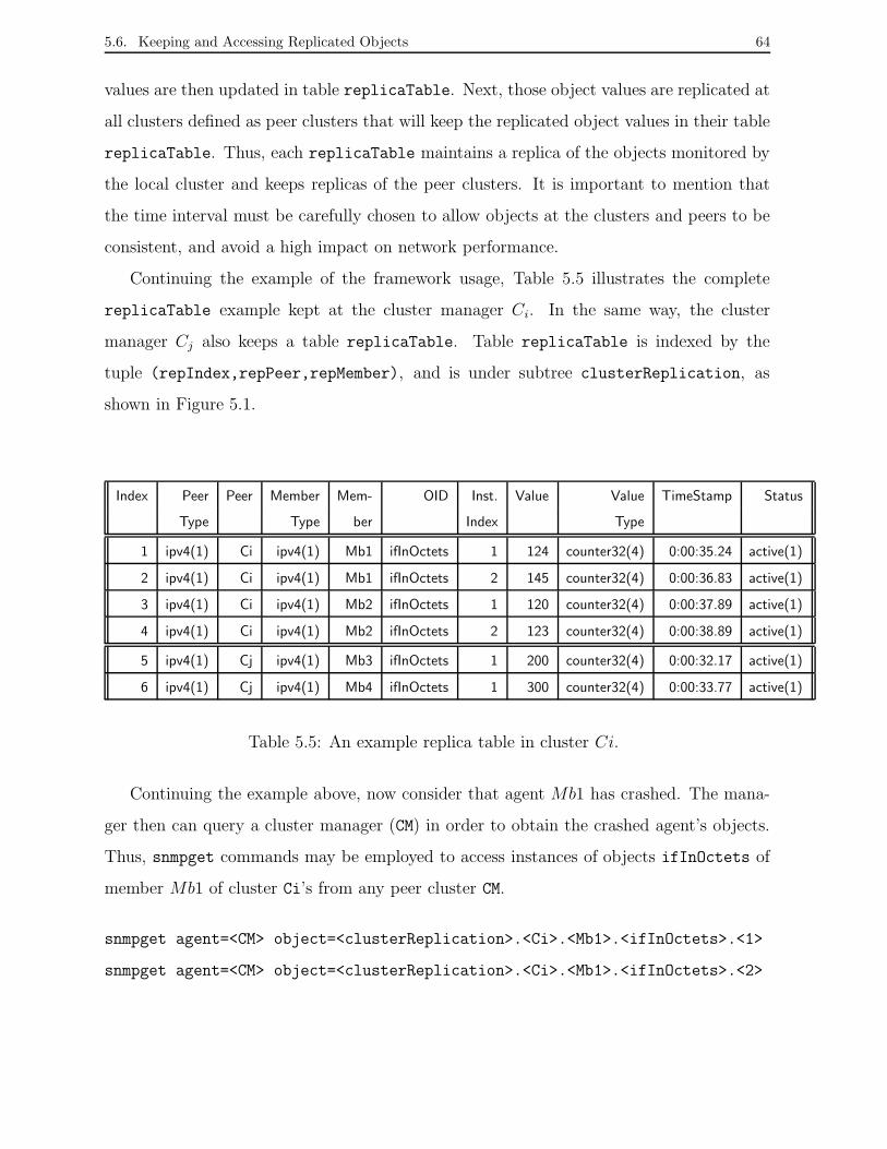
5.6. Keeping and Accessing Replicated Objects 64
values are then updated in table replicaTable. Next, those object values are replicated at
all clusters defined as peer clusters that will keep the replicated object values in their table
replicaTable. Thus, each replicaTable maintains a replica of the objects monitored by
the local cluster and keeps replicas of the peer clusters. It is important to mention that
the time interval must be carefully chosen to allow objects at the clusters and peers to be
consistent, and avoid a high impact on network performance.
Continuing the example of the framework usage, Table 5.5 illustrates the complete
replicaTable example kept at the cluster manager Ci. In the same way, the cluster
manager Cj also keeps a table replicaTable. Table replicaTable is indexed by the
tuple (repIndex,repPeer,repMember), and is under subtree clusterReplication, as
shown in Figure 5.1.
Index Peer Peer Member Mem- OID Inst. Value Value TimeStamp Status
Type Type ber Index Type
1 ipv4(1) Ci ipv4(1) Mb1 ifInOctets 1 124 counter32(4) 0:00:35.24 active(1)
2 ipv4(1) Ci ipv4(1) Mb1 ifInOctets 2 145 counter32(4) 0:00:36.83 active(1)
3 ipv4(1) Ci ipv4(1) Mb2 ifInOctets 1 120 counter32(4) 0:00:37.89 active(1)
4 ipv4(1) Ci ipv4(1) Mb2 ifInOctets 2 123 counter32(4) 0:00:38.89 active(1)
5 ipv4(1) Cj ipv4(1) Mb3 ifInOctets 1 200 counter32(4) 0:00:32.17 active(1)
6 ipv4(1) Cj ipv4(1) Mb4 ifInOctets 1 300 counter32(4) 0:00:33.77 active(1)
Table 5.5: An example replica table in cluster Ci.
Continuing the example above, now consider that agent Mb1 has crashed. The mana-
ger then can query a cluster manager (CM) in order to obtain the crashed agent’s objects.
Thus, snmpget commands may be employed to access instances of objects ifInOctets of
member Mb1 of cluster Ci’s from any peer cluster CM.
snmpget agent=<CM> object=<clusterReplication>.<Ci>.<Mb1>.<ifInOctets>.<1>
snmpget agent=<CM> object=<clusterReplication>.<Ci>.<Mb1>.<ifInOctets>.<2>
5.7. Conclusion 65
These commands are received by cluster manager CM, which can be either Ci or Cj,
because objects are replicated in both clusters. No matter which cluster is the cluster
manager (CM), the response received is as shown below.
response: object=clusterReplication.Ci.Mb1.ifInOctets.1 = 124
response: object=clusterReplication.Ci.Mb1.ifInOctets.2 = 145
This version of the SNMP agent clustering framework was documented into an Internet-
Draft, and published as a Draft document of the Distributed Management (DisMan) work-
ing group of the Internet Engineering Task Force (IETF). We present an overview of the
steps required to publish an RFC document at the IETF in Appendix A.
5.7 Conclusion
In this chapter, we presented the SNMP framework for object replication based on agent
clusters. The Replic-MIB allows the definition and usage of clusters, as well as the replica-
tion operation among clusters. The MIB is divided in two groups. The clusterDefinition
group consists of tables where are configured agents members, set of replicated objects,
and the peer clusters of the clusters. The clusterReplica group consists of one table that
keeps replicated objects of the clusters and from their peer clusters.
Along with the description of management clusters and cluster members, replicated
objects and peer clusters, an example of the framework usage was detailed. In additon, we
detailed which information about replicated objects is kept in the clusters, and how it can
be accessed in order to determine the source of replicated objects.
Although the SNMP agent clustering framework is complete, other managed objects
must be included over time since the members of the DisMan working group as well as
other IETF working groups must submit new suggestions and comments to the framework.
Some suggestions submitted in the IETF meetings are mentioned in Section 7.3 where we
discuss future work. In the next chapter, we present a fault network management tool
built based on the proposed SNMP framework
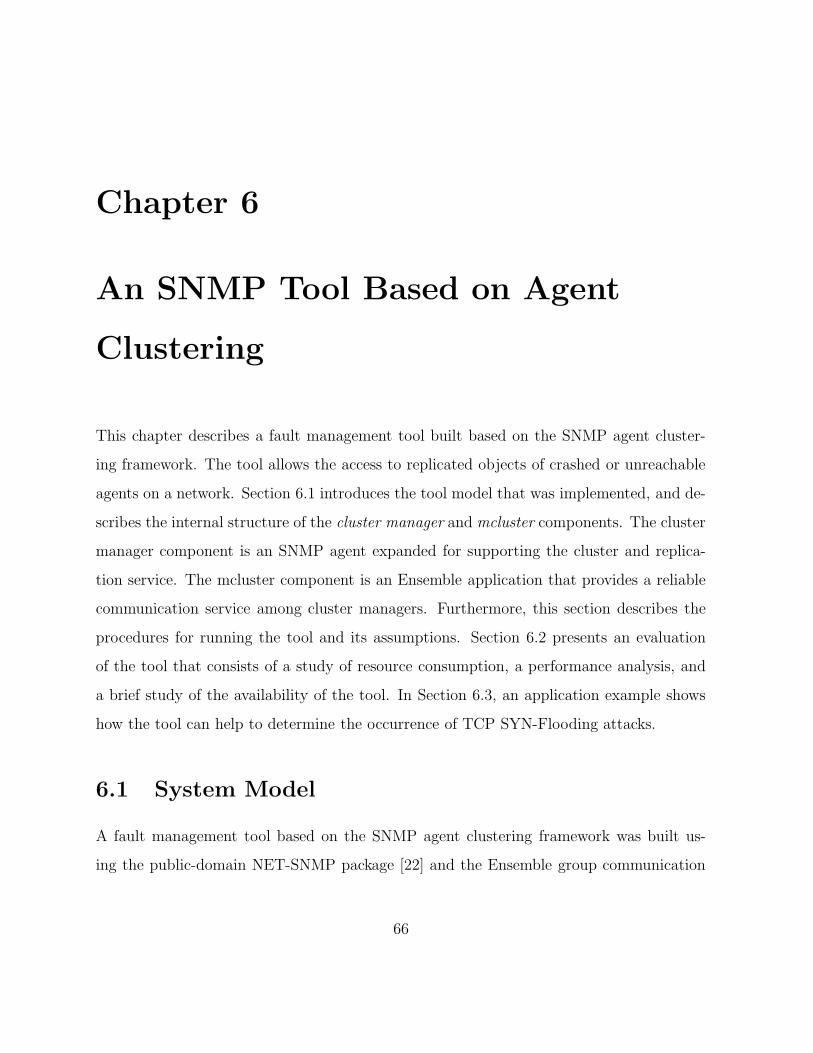
Chapter 6
An SNMP Tool Based on Agent
Clustering
This chapter describes a fault management tool built based on the SNMP agent cluster-
ing framework. The tool allows the access to replicated objects of crashed or unreachable
agents on a network. Section 6.1 introduces the tool model that was implemented, and de-
scribes the internal structure of the cluster manager and mcluster components. The cluster
manager component is an SNMP agent expanded for supporting the cluster and replica-
tion service. The mcluster component is an Ensemble application that provides a reliable
communication service among cluster managers. Furthermore, this section describes the
procedures for running the tool and its assumptions. Section 6.2 presents an evaluation
of the tool that consists of a study of resource consumption, a performance analysis, and
a brief study of the availability of the tool. In Section 6.3, an application example shows
how the tool can help to determine the occurrence of TCP SYN-Flooding attacks.
6.1 System Model
A fault management tool based on the SNMP agent clustering framework was built us-
ing the public-domain NET-SNMP package [22] and the Ensemble group communication
66
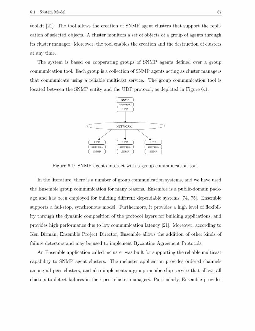
6.1. System Model 67
toolkit [21]. The tool allows the creation of SNMP agent clusters that support the repli-
cation of selected objects. A cluster monitors a set of objects of a group of agents through
its cluster manager. Moreover, the tool enables the creation and the destruction of clusters
at any time.
The system is based on cooperating groups of SNMP agents defined over a group
communication tool. Each group is a collection of SNMP agents acting as cluster managers
that communicate using a reliable multicast service. The group communication tool is
located between the SNMP entity and the UDP protocol, as depicted in Figure 6.1.
NETWORK
UDP
GROUP TOOL
SNMP
UDP
GROUP TOOL
SNMP
UDP
GROUP TOOL
SNMP
SNMP
GROUP TOOL
UDP
Figure 6.1: SNMP agents interact with a group communication tool.
In the literature, there is a number of group communication systems, and we have used
the Ensemble group communication for many reasons. Ensemble is a public-domain pack-
age and has been employed for building different dependable systems [74, 75]. Ensemble
supports a fail-stop, synchronous model. Furthermore, it provides a high level of flexibil-
ity through the dynamic composition of the protocol layers for building applications, and
provides high performance due to low communication latency [21]. Moreover, according to
Ken Birman, Ensemble Project Director, Ensemble allows the addition of other kinds of
failure detectors and may be used to implement Byzantine Agreement Protocols.
An Ensemble application called mcluster was built for supporting the reliable multicast
capability to SNMP agent clusters. The mcluster application provides ordered channels
among all peer clusters, and also implements a group membership service that allows all
clusters to detect failures in their peer cluster managers. Particularly, Ensemble provides

6.1. System Model 68
an application called gossip which simulates low-bandwidth broadcast for systems that
do not have IP multicast, but it also enables the development of systems based on IP
multicast.
Taking into account the SNMP framework seen in Chapter 5, a cluster manager must
include tables memberTable, repObjectTable, peerTable, and replicaTable. Thus, when a
cluster is activated, it automatically monitors the selected objects and replicates them
throughout the peer clusters. The technique of passive replication is employed among
cluster managers, hence each cluster manager is the leader for the replicated objects of its
agent members.
A cluster manager, besides monitoring the collection of objects of a group of agents,
receives and handles messages with replicated objects that arrive from other cluster man-
agers. For that, modules were added in order to parse each message and update the
replicated objects, as described in the next section. Moreover, a cluster manager can be
accessed using SNMP operations like any typical SNMP agent. Hence, the tool enables
any peer clusters to be queried in order to obtain the replicated objects of an agent that
belongs to a given cluster. Next, we describe the internal structure of a cluster manager,
and the mcluster group application.
6.1.1 Cluster Manager Structure
The structure of the SNMP agent was expanded with the inclusion of new modules that
provide the cluster and replication services. Hence, this agent can play the role of cluster
manager. The internal structure of a cluster manager is divided in four modules: agent,
thread scheduler, monitoring threads, and replica manager, as shown in Figure 6.2. A
cluster manager plays a dual role, being both a typical SNMP agent and an entity that
manages object replication.
The agent module performs the same operation of a common agent, keeping manage-
ment information stored at a local Management Information Base (MIB).
The thread scheduler module controls the time period in which monitoring and repli-
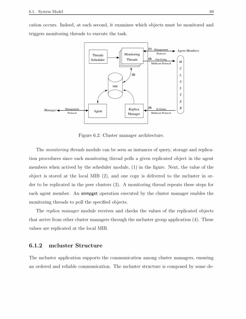
6.1. System Model 69
cation occurs. Indeed, at each second, it examines which objects must be monitored and
triggers monitoring threads to execute the task.
Replica
Threads Monitoring
ThreadsScheduler
ManagerIn Going
AgentProtocol
Management
(1)
(3)
(4)
(2)
MIB
Multicast Protocol
ManagementProtocol
Out GoingMulticast Protocol
U
S
E
L
T
C
Agent Members
M
RManager
Figure 6.2: Cluster manager architecture.
The monitoring threads module can be seen as instances of query, storage and replica-
tion procedures since each monitoring thread polls a given replicated object in the agent
members when actived by the scheduler module, (1) in the figure. Next, the value of the
object is stored at the local MIB (2), and one copy is delivered to the mcluster in or-
der to be replicated in the peer clusters (3). A monitoring thread repeats these steps for
each agent member. An snmpget operation executed by the cluster manager enables the
monitoring threads to poll the specified objects.
The replica manager module receives and checks the values of the replicated objects
that arrive from other cluster managers through the mcluster group application (4). These
values are replicated at the local MIB.
6.1.2 mcluster Structure
The mcluster application supports the communication among cluster managers, ensuring
an ordered and reliable communication. The mcluster structure is composed by some de-
6.1. System Model 70
fault Ensemble properties [21, 76], such as membership (Gmp), group view synchronization
(Sync), protocol switching (Switch), fragmentation-reassembly (Frag), failure detection
(Suspect), and flow control (Flow), as shown in Figure 6.3. In fact, Ensemble translates
those properties in a protocol stack during the compilation of the mcluster application.
Gmp
Sync
Switch
Frag
Suspect
Flow
Manager
CommunicationGroup
Mcluster
SNMP Cluster
(2) (3)
(4)(1)
Figure 6.3: mcluster architecture.
As figure 6.3 shows, the SNMP cluster manager delivers to the mcluster application
messages with objects to be replicated (1). The mcluster then multicasts these messages
to other SNMP cluster managers by Ensemble (2). At the same time, the mcluster can
also receive messages sent by other mclusters (3). Messages that arrive are examined and
next delivered to the SNMP cluster manager (4).
The Ensemble properties specified in the mcluster application ensure that the replicated
objects are sent to fault-free cluster managers. Particularly, the membership property
(Gmp) enables the mcluster to know which peer clusters are operational. The Ensemble
package currently provides about 50 properties also called as protocol layers [21, 77]. Some
of them are listed in Table 6.1. A full description of the Ensemble properties is found in
[21].
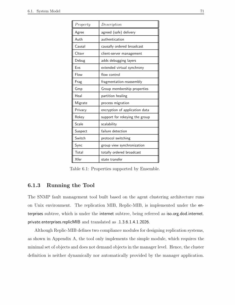
6.1. System Model 71
Property Description
Agree agreed (safe) delivery
Auth authentication
Causal causally ordered broadcast
Cltsvr client-server management
Debug adds debugging layers
Evs extended virtual synchrony
Flow flow control
Frag fragmentation-reassembly
Gmp Group membership properties
Heal partition healing
Migrate process migration
Privacy encryption of application data
Rekey support for rekeying the group
Scale scalability
Suspect failure detection
Switch protocol switching
Sync group view synchronization
Total totally ordered broadcast
Xfer state transfer
Table 6.1: Properties supported by Ensemble.
6.1.3 Running the Tool
The SNMP fault management tool built based on the agent clustering architecture runs
on Unix environment. The replication MIB, Replic-MIB, is implemented under the en-
terprises subtree, which is under the internet subtree, being referred as iso.org.dod.internet.
private.enterprises.replicMIB and translated as .1.3.6.1.4.1.2026.
Although Replic-MIB defines two compliance modules for designing replication systems,
as shown in Appendix A, the tool only implements the simple module, which requires the
minimal set of objects and does not demand objects in the manager level. Hence, the cluster
definition is neither dynamically nor automatically provided by the manager application.

6.1. System Model 72
In fact, the cluster configuration, i.e. definition of agent members, replicated objects, and
peer clusters, is made manually through configuration files added to a cluster manager.
Configuration F iles F ields
<device name>.ClusterMembers.conf Index, Ip Address, Port, Security, Status
<device name>.ReplicatedObjects.conf Index, Oid, Oid Index, Interval, State, Status
<device name>.PeerCluster.conf Index, Ip Address, RotIndex, Status
Table 6.2: Configuration files used for defining a cluster.
The names of the configuration files of a cluster take into account the name of the net-
work element that will be a cluster manager, being named as <device name>.ClusterMem-
bers.conf, <device name>.ReplicatedObjects.conf, and <device name>.PeerCluster.conf. The
<device name>.ClusterMembers.conf file defines the agent members, the <device name>.Re-
plicatedObjects.conf file defines the objects to be replicated, and the <device name>.Peer-
Cluster.conf file defines the peer clusters where the managed objects are replicated. Table
6.2 shows the parameters to be configured at each file. Thus, when a cluster manager is
started, it reads these files and builds the memberTable, repObjectTable, and peerTable
tables, respectively.
The following procedures are needed for running the fault management tool. First, the
mcluster application must be started in all network elements where SNMP agents will be
cluster managers. The mcluster applications will support the communication among the
cluster managers.
% mcluster &
Second, each SNMP agent that will act as cluster manager must be started like an ordi-
nary SNMP agent, as shown below. Such agents must have implemented the Replic-MIB
in order to be activated as cluster managers.
6.2. Evaluation of the Tool 73
% snmpd -p <port>
Once SNMP agents are running as cluster managers, it is possible to issue a query
to them using SNMP operations like snmpget or snmpwalk. Parameters to execute these
operations are shown below.
% snmpget or snmpwalk -p <port> <destination host> <security> <oid>
A full example of the operation of the fault management tool is given in Appendix
B. The example presents procedures and parameters needed to configure clusters and to
access the replicated objects. Next, we describe an extensive evaluation of the tool carried
out at a local area network.
6.2 Evaluation of the Tool
This section presents an evaluation of the SNMP monitoring tool running on a local area
network. The evaluation includes a study of resource consumption, a performance analysis,
and an availability analysis [78, 79, 80, 81]. The study of resource consumption estimates
the network resources needed to guarantee that the monitoring tool can provide replication
of managed objects [82]. The performance analysis presents the operation of a cluster
manager by monitoring given sets of objects, the performance of the mcluster application
by exchanging messages among cluster managers, and the impact of the number of peer
clusters of a cluster [83]. The availability analysis shows the operation of cluster managers
when peer clusters fail. In particular, this last analysis considers only the behavior of the
mcluster application.
6.2.1 Impact on Network Resources
This subsection presents the evaluation of both space and communication costs imposed
by the SNMP monitoring tool based on the agent clustering architecture.
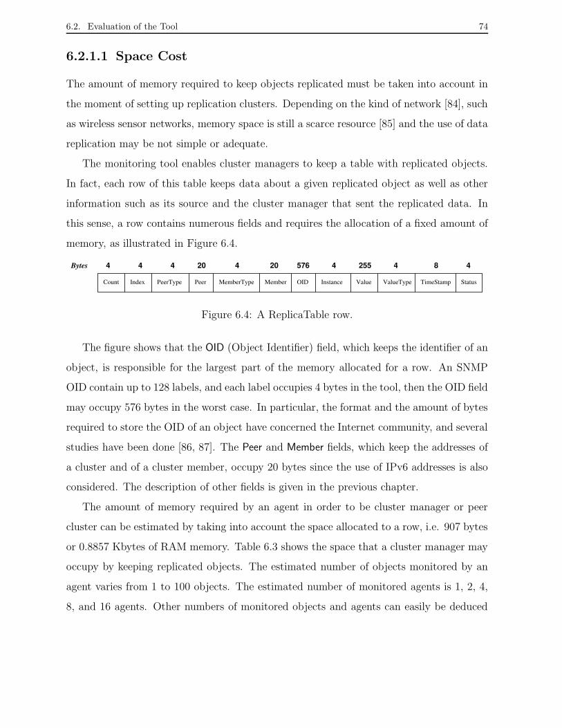
6.2. Evaluation of the Tool 74
6.2.1.1 Space Cost
The amount of memory required to keep objects replicated must be taken into account in
the moment of setting up replication clusters. Depending on the kind of network [84], such
as wireless sensor networks, memory space is still a scarce resource [85] and the use of data
replication may be not simple or adequate.
The monitoring tool enables cluster managers to keep a table with replicated objects.
In fact, each row of this table keeps data about a given replicated object as well as other
information such as its source and the cluster manager that sent the replicated data. In
this sense, a row contains numerous fields and requires the allocation of a fixed amount of
memory, as illustrated in Figure 6.4.
StatusValueType TimeStampValueInstanceOIDMemberMemberTypePeerPeerTypeIndexCount
20444 4 20 576 255 4 8 44Bytes
Figure 6.4: A ReplicaTable row.
The figure shows that the OID (Object Identifier) field, which keeps the identifier of an
object, is responsible for the largest part of the memory allocated for a row. An SNMP
OID contain up to 128 labels, and each label occupies 4 bytes in the tool, then the OID field
may occupy 576 bytes in the worst case. In particular, the format and the amount of bytes
required to store the OID of an object have concerned the Internet community, and several
studies have been done [86, 87]. The Peer and Member fields, which keep the addresses of
a cluster and of a cluster member, occupy 20 bytes since the use of IPv6 addresses is also
considered. The description of other fields is given in the previous chapter.
The amount of memory required by an agent in order to be cluster manager or peer
cluster can be estimated by taking into account the space allocated to a row, i.e. 907 bytes
or 0.8857 Kbytes of RAM memory. Table 6.3 shows the space that a cluster manager may
occupy by keeping replicated objects. The estimated number of objects monitored by an
agent varies from 1 to 100 objects. The estimated number of monitored agents is 1, 2, 4,
8, and 16 agents. Other numbers of monitored objects and agents can easily be deduced

6.2. Evaluation of the Tool 75
using this table.
No. of Memory Quantity (Kbytes) X No. of Agents
Objects 1 Ag 2 Ags 4 Ags 8 Ags 16 Ags
1 0.88 1.77 3.54 7.08 14.17
5 4.42 8.85 17.71 35.42 70.85
10 8.85 17.71 35.42 70.85 141.71
15 13.28 26.57 53.14 106.28 212.56
20 17.71 35.42 70.85 141.71 283.42
30 26.57 53.14 106.28 212.56 425.13
40 35.42 70.85 141.71 283.42 566.84
100 88.57 177.14 354.28 708.56 1,417.12
Table 6.3: Space allocated by one cluster to keep replicated objects.
Thus, for example, a replication service of managed objects that creates two clusters to
monitor 15 objects of 8 agents and replicate each other will require 212.56 Kbytes in each
cluster manager. Each cluster manager will require 106.28 Kbytes to keep their replicated
objects and more 106.28 Kbytes to keep the objects sent by the other cluster manager.
Hence, using the memory space cost of a row, we can determine the space required for
different cluster configurations in order to run a replication service.
6.2.1.2 Communication Cost
The communication cost to keep the object replication service comprises of two parts. The
first part comes from periodic queries to the objects of the agent members of a cluster.
The second part comes from the replication of those objects in the peer clusters. In this
sense, the computation of the bandwidth required for a cluster can be based on defining
the monitoring cost and replication cost. In the following, we present the time intervals
applied to define those metrics.
• monitoring interval: the time interval in which a cluster manager periodically polls
all its agent members to update its replica. This interval is denoted as ∆m. The NET-
SNMP package particularly establishes that the timeout to receive the response of

6.2. Evaluation of the Tool 76
a query try is one second and that up to five retries can be done to each SNMP
query. Hence, a manager application actually assumes that an SNMP query was
not successful only after the first query try and all query retries have been carried
out, which can take together up to seven seconds. Thus, in order to avoid that two
or more SNMP queries to an object happen at same time, we advise a monitoring
interval of at least 10 seconds.
• query time: the time actually spent to monitor all objects inside a monitoring time.
This time is denoted as ∆q, being ∆q ≤ ∆m.
• replication time: the time spent to multicast the replicated objects of a cluster to its
peer clusters. This time is denoted as ∆r.
Once we defined the monitoring time and the replication time, we can define the moni-
toring cost and the replication cost. For simplicity, we consider that as ∆q as ∆r are equal
to the time interval of a query successful on the first try, i.e. a query only spends one
second. Furthermore, we assume that in case of a query failure, a new retry implies in
extra monitoring cost. We can thus state the monitoring cost and replication cost as follows:
Let Mi denote the bandwidth required by cluster manager of cluster ci to monitor all
its replicated objects. Hence, the monitoring cost of cluster ci is expressed as:
Mi =
(
No. of queries × message size of a query operation
query time (∆qi)
)
× No. of agents (6.1)
The message size of a query operation (≡ 1500 bytes) is the default size of an SNMP
message[39], the number of queries is the amount of monitored objects, and the query time
is the time required to monitor all objects.
Let Ri denote the required bandwidth to multicast the objects replicated of cluster ci
in the peer clusters. Hence, the replication cost of cluster ci is expressed as:
Ri =No. of multicast messages × multicast message size
replication time (∆ri)
(6.2)
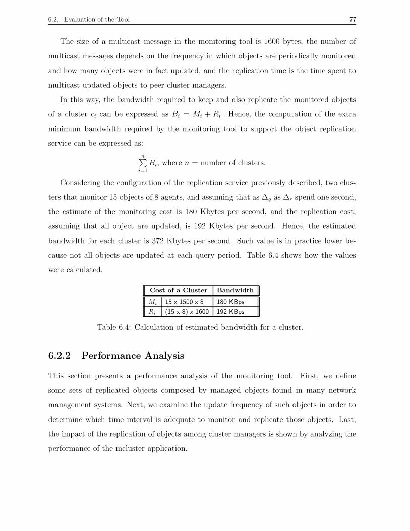
6.2. Evaluation of the Tool 77
The size of a multicast message in the monitoring tool is 1600 bytes, the number of
multicast messages depends on the frequency in which objects are periodically monitored
and how many objects were in fact updated, and the replication time is the time spent to
multicast updated objects to peer cluster managers.
In this way, the bandwidth required to keep and also replicate the monitored objects
of a cluster ci can be expressed as Bi = Mi + Ri. Hence, the computation of the extra
minimum bandwidth required by the monitoring tool to support the object replication
service can be expressed as:
n∑
i=1
Bi, where n = number of clusters.
Considering the configuration of the replication service previously described, two clus-
ters that monitor 15 objects of 8 agents, and assuming that as ∆q as ∆r spend one second,
the estimate of the monitoring cost is 180 Kbytes per second, and the replication cost,
assuming that all object are updated, is 192 Kbytes per second. Hence, the estimated
bandwidth for each cluster is 372 Kbytes per second. Such value is in practice lower be-
cause not all objects are updated at each query period. Table 6.4 shows how the values
were calculated.
Cost of a Cluster Bandwidth
Mi 15 x 1500 x 8 180 KBps
Ri (15 x 8) x 1600 192 KBps
Table 6.4: Calculation of estimated bandwidth for a cluster.
6.2.2 Performance Analysis
This section presents a performance analysis of the monitoring tool. First, we define
some sets of replicated objects composed by managed objects found in many network
management systems. Next, we examine the update frequency of such objects in order to
determine which time interval is adequate to monitor and replicate those objects. Last,
the impact of the replication of objects among cluster managers is shown by analyzing the
performance of the mcluster application.

6.2. Evaluation of the Tool 78
6.2.2.1 Sets of Objects Evaluated
The definition of a meaningful collection of objects that can be found in any sort of network
is a task very hard. In the same way, it is a challenge for a network administrator to predict
which information of a network element should be preserved in case this element becomes
faulty. We choose three groups of objects from the MIB-2, which is the standard TCP/IP
protocol’s MIB, in order to exemplify the behavior of managed objects in a network. IP,
TCP and UDP groups, seen in Section 2.2.2, define managed objects that hold information
about the operational state of the corresponding protocols running in a network element
and are fundamental to monitor the network behavior. In the following, we show the sets
of selected objects of each group.
The first set comprises 14 IP objects specified in Table 6.5. The second set comprises
9 TCP objects specified in Table 6.6. The last set comprises 4 UDP objects specified in
Table 6.7. Note that we include an Index field in all three tables. This field is used to
identify each object in Section 6.2.2.2. The complete description of the objects is given in
Appendix C.
Index IP Object Name Identifier
1 ipInReceives .1.3.6.1.2.1.4.3.0
2 ipInHdrErrors .1.3.6.1.2.1.4.4.0
3 ipInAddrErrors .1.3.6.1.2.1.4.5.0
4 ipInDiscards .1.3.6.1.2.1.4.8.0
5 ipInDelivers .1.3.6.1.2.1.4.9.0
6 ipOutRequests .1.3.6.1.2.1.4.10.0
7 ipOutDiscards .1.3.6.1.2.1.4.11.0
8 ipReasmTimeout .1.3.6.1.2.1.4.13.0
9 ipReasmReqds .1.3.6.1.2.1.4.14.0
10 ipReasmOKs .1.3.6.1.2.1.4.15.0
11 ipReasmFails .1.3.6.1.2.1.4.16.0
12 ipFrafOKs .1.3.6.1.2.1.4.17.0
13 ipFragFails .1.3.6.1.2.1.4.18.0
14 ipFragCreates .1.3.6.1.2.1.4.19.0
Table 6.5: Set of IP evaluated objects.
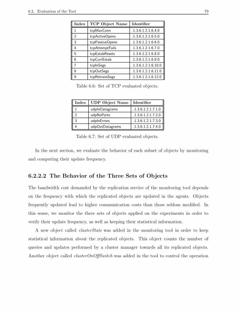
6.2. Evaluation of the Tool 79
Index TCP Object Name Identifier
1 tcpMaxConn .1.3.6.1.2.1.6.4.0
2 tcpActiveOpens .1.3.6.1.2.1.6.5.0
3 tcpPassiveOpens .1.3.6.1.2.1.6.6.0
4 tcpAttemptFails .1.3.6.1.2.1.6.7.0
5 tcpEstabResets .1.3.6.1.2.1.6.8.0
6 tcpCurrEstab .1.3.6.1.2.1.6.9.0
7 tcpInSegs .1.3.6.1.2.1.6.10.0
8 tcpOutSegs .1.3.6.1.2.1.6.11.0
9 tcpRetransSegs .1.3.6.1.2.1.6.12.0
Table 6.6: Set of TCP evaluated objects.
Index UDP Object Name Identifier
1 udpInDatagrams .1.3.6.1.2.1.7.1.0
2 udpNoPorts .1.3.6.1.2.1.7.2.0
3 udpInErrors .1.3.6.1.2.1.7.3.0
4 udpOutDatagrams .1.3.6.1.2.1.7.4.0
Table 6.7: Set of UDP evaluated objects.
In the next section, we evaluate the behavior of each subset of objects by monitoring
and computing their update frequency.
6.2.2.2 The Behavior of the Three Sets of Objects
The bandwidth cost demanded by the replication service of the monitoring tool depends
on the frequency with which the replicated objects are updated in the agents. Objects
frequently updated lead to higher communication costs than those seldom modified. In
this sense, we monitor the three sets of objects applied on the experiments in order to
verify their update frequency, as well as keeping their statistical information.
A new object called clusterStats was added in the monitoring tool in order to keep
statistical information about the replicated objects. This object counts the number of
queries and updates performed by a cluster manager towards all its replicated objects.
Another object called clusterOnOffSwitch was added in the tool to control the operation

6.2. Evaluation of the Tool 80
time of a cluster. These two objects together provide facilities for monitoring the update
frequency of the replicated object sets considering a given selected time period.
The cluster manager monitored during 30 minutes each one of the three subsets of
IP, TCP and UDP objects of an agent member of the cluster. There was only one agent
member in each cluster. The monitoring interval configured for each query was 3 seconds.
We choose such monitoring interval and time period for monitoring the objects because it
allows us to check some hundreds of queries issued to each object. Hence, we considered
the number of queries a relevant sample. Furthermore, both the cluster manager and the
agent member were hosted in machines under conditions of normal workload, i.e. they
were not dedicated exclusively to the experiment.
We present the behavior of the sets of objects in the following. For simplicity of graphs,
we have included the indexes that identify the objects in Tables 6.5, 6.6 and 6.7 instead of
their numbers or names.
The graph in Figure 6.5 shows the number of queries and the number of updates on
the set of IP objects. During 30 minutes, almost 600 queries were issued for all objects.
The indexes 1, 5, 6, and 14, respectively, ipInReceives, ipInDelivers, ipOutRequests, and
ipFragCreates objects, were updated by around 350 queries, whereas the other objects did
not suffer any update in the period.
0050 100 150 200 250 300 350 400 450 500 550 600 650 700 750 800
1 2 3 4 5 6 7 8 9 10 11 12 13 14
Num
ber o
f Que
ries
Index of the IP Objects
Set of IP Objects Monitored During 30 minutes
Number of queriesNumber of updates
Figure 6.5: Set of IP objects: update frequency for 3 seconds of monitoring time.

6.2. Evaluation of the Tool 81
If we take into account that four objects suffered nearly 350 updates, i.e. nearly half
of all their queries led to updates, and also consider a uniform distribution in the update
of all objects, we can suppose a monitoring time of 6 seconds, which is twice the config-
ured monitoring time, to be enough to collect information about the four objects. The
other objects, as they did not suffer changes in this period, could be monitored in larger
monitoring intervals.
0050 100 150 200 250 300 350 400 450 500 550 600 650 700 750 800
1 2 3 4 5 6 7 8 9
Num
ber o
f Que
ries
Index of the TCP Objects
Set of TCP Objects Monitored During 30 minutes
Number of queriesNumber of updates
Figure 6.6: Set of TCP objects: update frequency for 3 seconds of monitoring time.
The graph in Figure 6.6 shows the number of queries and the number of updates
considering the set of TCP objects. Almost 600 queries were executed for all objects.
Notice that only three objects, 2, 7, and 8, respectively, tcpActiveOpens, tcpInSegs, and
tcpOutSegs, were updated by around 7 updates each one. Object number 6, tcpCurrEstab,
was updated by only 2 queries.
If we consider the number of updates of the tcpActiveOpens and tcpCurrEstab objects,
which keep information about the number of established TCP connections, and the number
of updates verified in the other two objects, which keep information about the traffic on the
established TCP connections, we can suppose that few TCP connections were established
at the selected time period and such connections implied in a low traffic on network.
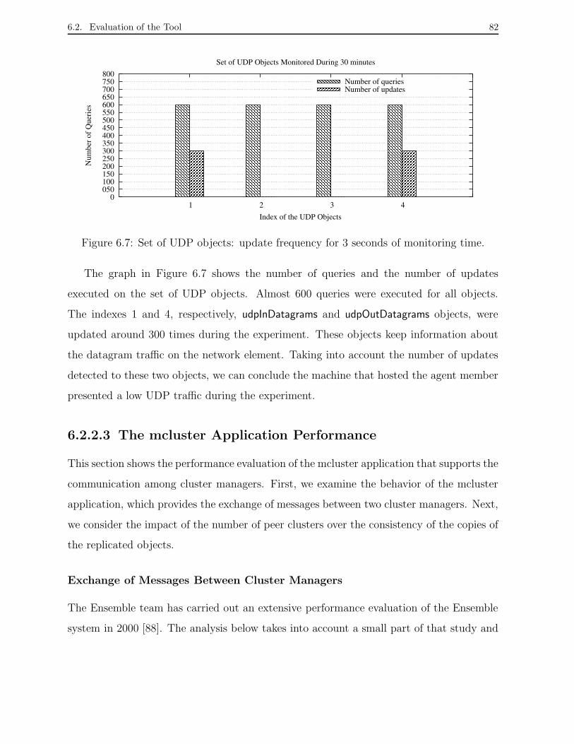
6.2. Evaluation of the Tool 82
0050 100 150 200 250 300 350 400 450 500 550 600 650 700 750 800
1 2 3 4
Num
ber o
f Que
ries
Index of the UDP Objects
Set of UDP Objects Monitored During 30 minutes
Number of queriesNumber of updates
Figure 6.7: Set of UDP objects: update frequency for 3 seconds of monitoring time.
The graph in Figure 6.7 shows the number of queries and the number of updates
executed on the set of UDP objects. Almost 600 queries were executed for all objects.
The indexes 1 and 4, respectively, udpInDatagrams and udpOutDatagrams objects, were
updated around 300 times during the experiment. These objects keep information about
the datagram traffic on the network element. Taking into account the number of updates
detected to these two objects, we can conclude the machine that hosted the agent member
presented a low UDP traffic during the experiment.
6.2.2.3 The mcluster Application Performance
This section shows the performance evaluation of the mcluster application that supports the
communication among cluster managers. First, we examine the behavior of the mcluster
application, which provides the exchange of messages between two cluster managers. Next,
we consider the impact of the number of peer clusters over the consistency of the copies of
the replicated objects.
Exchange of Messages Between Cluster Managers
The Ensemble team has carried out an extensive performance evaluation of the Ensemble
system in 2000 [88]. The analysis below takes into account a small part of that study and

6.2. Evaluation of the Tool 83
is based on advices of the Ensemble maintenance group [88]. The analysis introduces a
performance comparison among the communication provided by mcluster application and
the communication only supported by Ensemble system or UDP.
The analysis considers the latency required to the exchange of messages between cluster
managers. Latency measures followed the measurement standard for point-to-point com-
munication called ping-pong. The measurement included two machines and verified the
elapsed time between the sending of a message to the target machine and its immediate
response back to the source machine.
The measurements were taken at a 100 Mbps Ethernet local area network composed
by 20 machines with RAM memory from 64 MB to 512 MB. The machines run the
Linux/Debian 2.6.0 operating system and are connected to a 3Com switch (3C17300 Su-
perStack). All experiments occurred in a pair of machines with Pentium III, 800Mhz, 196
MB memory, and Linux/Debian 2.6.0 operating system. Users executed applications such
as browsers and text editors during the experiments. In the following, we described the
other two communication levels examined: Ensemble system and UDP socket.
The Ensemble package includes some programs such as the perf application [76]. This
application carries out performance tests on the Ensemble system, such as latency measure
and evaluates the Ensemble protocols stacks. Such protocol stacks provide the group
properties used to build an Ensemble application. FIFO stack (standard), authenticated
stack (AUTH), and totally ordered protocol stack (ORDER) are some of these protocol
stacks [88]. In the experiment, the perf program measured the latency of the ORDER
protocol stack of the Ensemble system running in the network. As the UDP protocol is the
main communication infrastructure of the Ensemble system, we measured the latency of a
simple communication via UDP using a client socket program and a server socket program
built in C language [89].
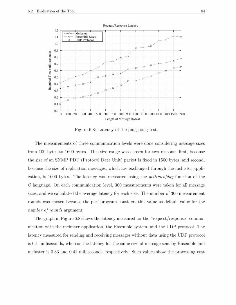
6.2. Evaluation of the Tool 84
0.0
0.1
0.2
0.3
0.4
0.5
0.6
0.7
0.8
0.9
1.0
1.1
1.2
0 100 200 300 400 500 600 700 800 900 1000 1100 1200 1300 1400 1500 1600
Req
uire
d T
ime
(mill
isec
onds
)
Length of Message (bytes)
Request/Response Latency
MclusterEnsemble StackUDP Protocol
Figure 6.8: Latency of the ping-pong test.
The measurements of three communication levels were done considering message sizes
from 100 bytes to 1600 bytes. This size range was chosen for two reasons: first, because
the size of an SNMP PDU (Protocol Data Unit) packet is fixed in 1500 bytes, and second,
because the size of replication messages, which are exchanged through the mcluster appli-
cation, is 1600 bytes. The latency was measured using the gettimeofday function of the
C language. On each communication level, 300 measurements were taken for all message
sizes, and we calculated the average latency for each size. The number of 300 measurement
rounds was chosen because the perf program considers this value as default value for the
number of rounds argument.
The graph in Figure 6.8 shows the latency measured for the “request/response” commu-
nication with the mcluster application, the Ensemble system, and the UDP protocol. The
latency measured for sending and receiving messages without data using the UDP protocol
is 0.1 milliseconds, whereas the latency for the same size of message sent by Ensemble and
mcluster is 0.33 and 0.41 milliseconds, respectively. Such values show the processing cost

6.2. Evaluation of the Tool 85
of the protocol stacks regardless of the data message size.
Note that the latencies of the communication using Ensemble and UDP become near
to each other when the message size increases. Such behavior occurs because UDP is the
default data transport protocol of the Ensemble system, as mentioned earlier. Moreover,
Ensemble contains the Frag property, which fragments and reassembles messages, to control
the size of messages, see Table 6.1.
When comparing only latencies achieved using Ensemble and mcluster, we note the
latencies using mcluster are higher mainly to messages from 900 up to 1600 bytes. The
internal operation of the protocol stack, .i.e. group properties configured in the mcluster
application must be the reason for such values.
In particular, our main goal was to measure the latency of the messages of 1600 bytes,
which is the size of a replication message sent by the mcluster application. In this sense,
the latency to send and receive a replication message is around 1.1 milliseconds using the
mcluster application, 0.77 milliseconds using the Ensemble system, and 0.65 milliseconds
using the UDP protocol. If we consider that the mcluster application includes the group
properties mentioned in Section 6.1.2 , and that such properties require additional process-
ing, then the mcluster application’s latency, which corresponds to an increase of 40% on
the latency measured using the Ensemble system, is not high.
Different Sizes of the Peer Clusters Group
This evaluation presents the behavior of the latencies required to different group sizes of
cluster managers. In this sense, the effective communication among cluster managers is
important in order to guarantee the consistency of replicated objects. The experiments
thus analyze the scalability constraints of the mcluster application, which is fundamental
to guarantee the exchange of messages among cluster managers.
In each test, a cluster manager, through its mcluster application, sends a multicast
message to all peer clusters and next receives a unicast message from all peer clusters.
Furthermore, all multicast and unicast messages contain a replication message with infor-

6.2. Evaluation of the Tool 86
mation equivalent to messages with one replicated object. The size of a replication message
is 1600 bytes, whereas the size of a mcluster message, i.e. multicast or unicast message, is
4096 bytes, which is the default size established by Ensemble.
The number of cluster managers selected as peer clusters for a cluster manager varies
from 1 to 6. All experiments took into account the execution in sequence of 300 test
rounds to each peer cluster group and were repeated 12 times in order to confirm the
results. However, the graphs show only one of the results measured for each experiment.
The experiments were run in the same environment described previously in this sec-
tion. Cluster managers were hosted in seven machines, and a given cluster manager was
responsible for sending each multicast message. Hence, it controlled the start of each test
round. The workload on all machines and the traffic on the network were normal and pre-
sented the same characteristics described previously. In the following, we show the graphs
with the latency measured in the communication between a cluster manager and its peer
clusters.
0.00.51.01.52.02.53.03.54.04.55.05.56.06.57.07.58.08.59.09.5
10.0
0 50 100 150 200 250 300
Req
uire
d T
ime
(mill
isec
onds
)
Number of Rounds
Request/Response Latency for A Replication Message
Latency 1 peer cluster
0.00.51.01.52.02.53.03.54.04.55.05.56.06.57.07.58.08.59.09.5
10.0
0 50 100 150 200 250 300
Req
uire
d T
ime
(mill
isec
onds
)
Number of Rounds
Request/Response Latency for A Replication Message
Latency 2 peer clusters
Figure 6.9: Latency required to the exchange of messages with 1 and 2 peer clusters.
The graphs in Figure 6.9 show the latency measured for 1 and 2 peer clusters. Although
the graphs show several values going up to 5 milliseconds, the values are in general around
2 milliseconds. Hence, we can conclude that the communication among these numbers of
peer clusters at a local area network is highly stable.
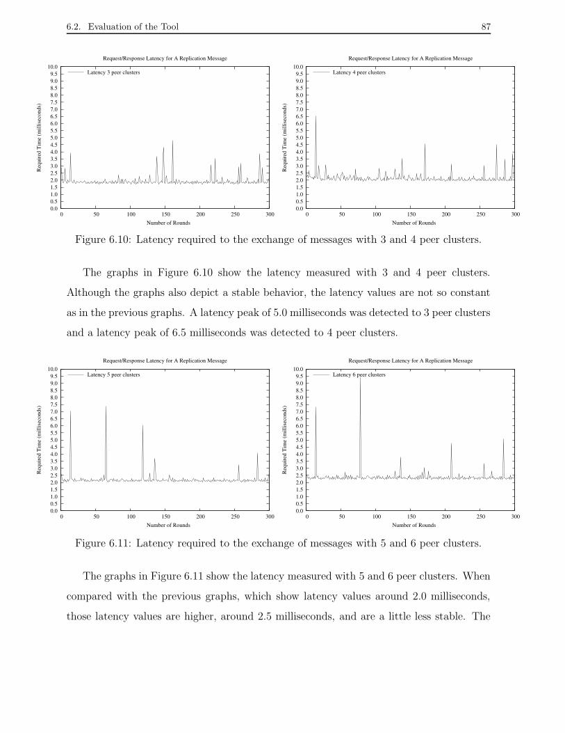
6.2. Evaluation of the Tool 87
0.00.51.01.52.02.53.03.54.04.55.05.56.06.57.07.58.08.59.09.5
10.0
0 50 100 150 200 250 300
Req
uire
d T
ime
(mill
isec
onds
)
Number of Rounds
Request/Response Latency for A Replication Message
Latency 3 peer clusters
0.00.51.01.52.02.53.03.54.04.55.05.56.06.57.07.58.08.59.09.5
10.0
0 50 100 150 200 250 300
Req
uire
d T
ime
(mill
isec
onds
)
Number of Rounds
Request/Response Latency for A Replication Message
Latency 4 peer clusters
Figure 6.10: Latency required to the exchange of messages with 3 and 4 peer clusters.
The graphs in Figure 6.10 show the latency measured with 3 and 4 peer clusters.
Although the graphs also depict a stable behavior, the latency values are not so constant
as in the previous graphs. A latency peak of 5.0 milliseconds was detected to 3 peer clusters
and a latency peak of 6.5 milliseconds was detected to 4 peer clusters.
0.00.51.01.52.02.53.03.54.04.55.05.56.06.57.07.58.08.59.09.5
10.0
0 50 100 150 200 250 300
Req
uire
d T
ime
(mill
isec
onds
)
Number of Rounds
Request/Response Latency for A Replication Message
Latency 5 peer clusters
0.00.51.01.52.02.53.03.54.04.55.05.56.06.57.07.58.08.59.09.5
10.0
0 50 100 150 200 250 300
Req
uire
d T
ime
(mill
isec
onds
)
Number of Rounds
Request/Response Latency for A Replication Message
Latency 6 peer clusters
Figure 6.11: Latency required to the exchange of messages with 5 and 6 peer clusters.
The graphs in Figure 6.11 show the latency measured with 5 and 6 peer clusters. When
compared with the previous graphs, which show latency values around 2.0 milliseconds,
those latency values are higher, around 2.5 milliseconds, and are a little less stable. The

6.2. Evaluation of the Tool 88
experiments detected latency peaks of 7.5 and 9.5 milliseconds but such values were not
so frequent.
0.0
0.5
1.0
1.5
2.0
2.5
3.0
3.5
4.0
4.5
5.0
1 2 3 4 5 6 7 8 9 10 11 12
Req
uire
d T
ime
(mill
isec
onds
)
Number of The Experiment
Average Latency of 300 Rounds by Test
1 PC2 PCs3 PCs4 PCs5 PCs6 PCs
Figure 6.12: Average latency versus number of peer clusters.
The graph in Figure 6.12 shows a summary with the average latency of each one of
12 experiments carried out for each size of peer cluster group (PCs). Recall that each
experiment took into account the execution of 300 test rounds. Note that in general the
difference among the average latency measured with 1 PC and 6 PCs is small, around 0.8
milliseconds. Hence, we conclude that, although some high peaks of latency have been
showed on the graphs, the communication among a cluster manager and up to 6 peer
clusters is able to guarantee consistency among copies of a replica.
6.2.3 Availability Analysis
This section shows the behavior of the mcluster application in the presence of faulty cluster
managers. The analysis verifies the latency required to multicast messages for peer cluster
managers subject to faults.
The experiment involved seven cluster managers hosted in different machines and was
carried out at the same local area network described in the previous section. A given
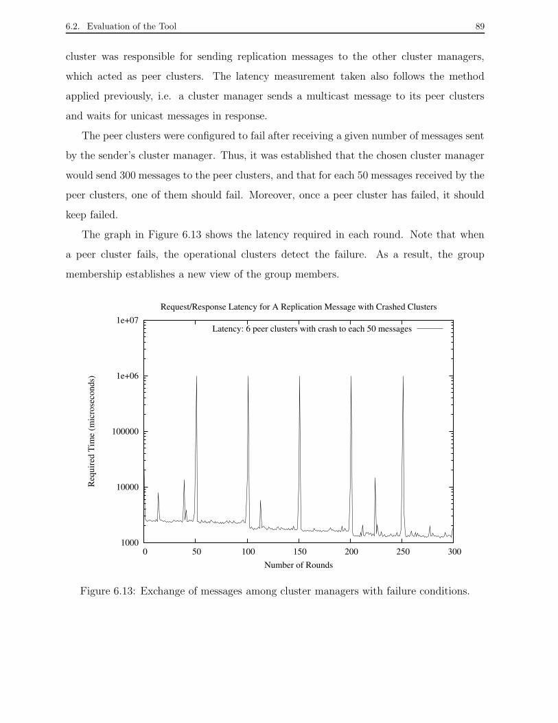
6.2. Evaluation of the Tool 89
cluster was responsible for sending replication messages to the other cluster managers,
which acted as peer clusters. The latency measurement taken also follows the method
applied previously, i.e. a cluster manager sends a multicast message to its peer clusters
and waits for unicast messages in response.
The peer clusters were configured to fail after receiving a given number of messages sent
by the sender’s cluster manager. Thus, it was established that the chosen cluster manager
would send 300 messages to the peer clusters, and that for each 50 messages received by the
peer clusters, one of them should fail. Moreover, once a peer cluster has failed, it should
keep failed.
The graph in Figure 6.13 shows the latency required in each round. Note that when
a peer cluster fails, the operational clusters detect the failure. As a result, the group
membership establishes a new view of the group members.
1000
10000
100000
1e+06
1e+07
0 50 100 150 200 250 300
Req
uire
d T
ime
(mic
rose
cond
s)
Number of Rounds
Request/Response Latency for A Replication Message with Crashed Clusters
Latency: 6 peer clusters with crash to each 50 messages
Figure 6.13: Exchange of messages among cluster managers with failure conditions.
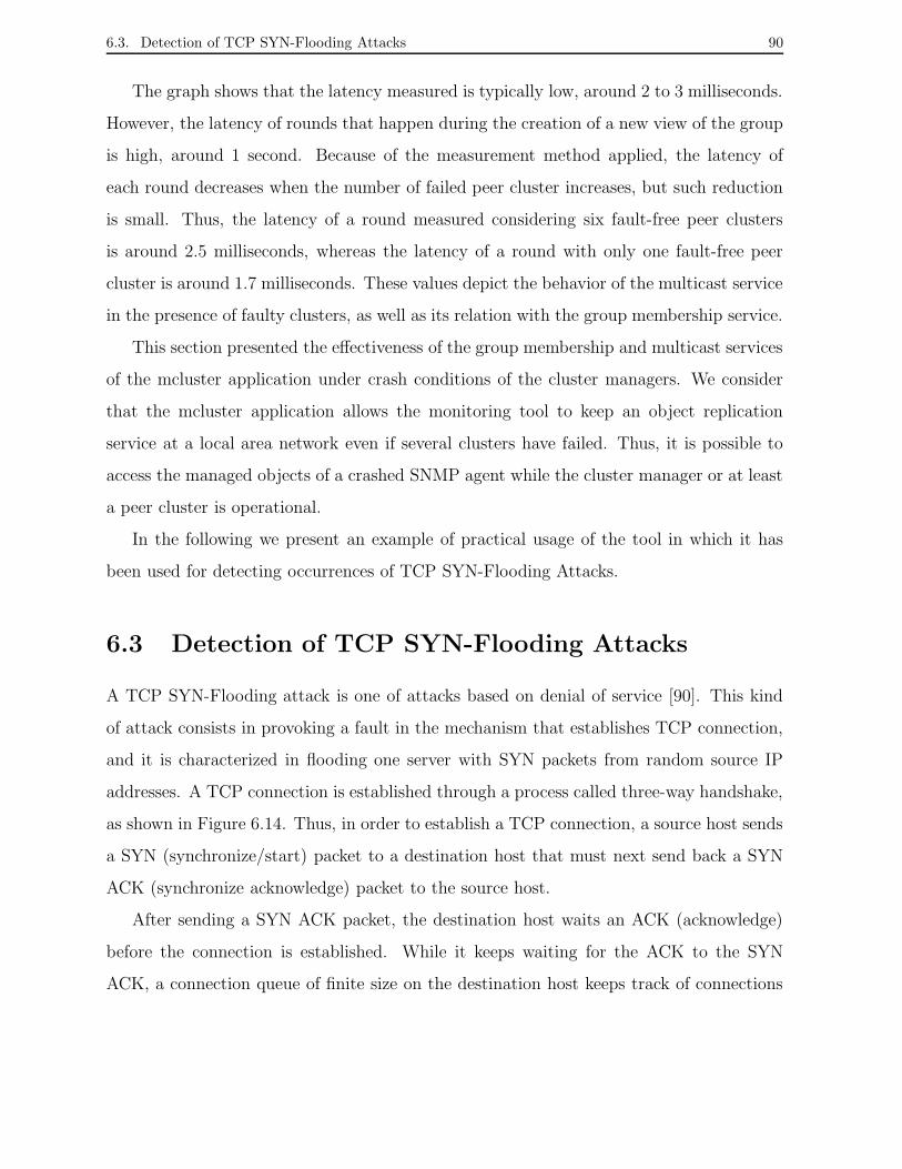
6.3. Detection of TCP SYN-Flooding Attacks 90
The graph shows that the latency measured is typically low, around 2 to 3 milliseconds.
However, the latency of rounds that happen during the creation of a new view of the group
is high, around 1 second. Because of the measurement method applied, the latency of
each round decreases when the number of failed peer cluster increases, but such reduction
is small. Thus, the latency of a round measured considering six fault-free peer clusters
is around 2.5 milliseconds, whereas the latency of a round with only one fault-free peer
cluster is around 1.7 milliseconds. These values depict the behavior of the multicast service
in the presence of faulty clusters, as well as its relation with the group membership service.
This section presented the effectiveness of the group membership and multicast services
of the mcluster application under crash conditions of the cluster managers. We consider
that the mcluster application allows the monitoring tool to keep an object replication
service at a local area network even if several clusters have failed. Thus, it is possible to
access the managed objects of a crashed SNMP agent while the cluster manager or at least
a peer cluster is operational.
In the following we present an example of practical usage of the tool in which it has
been used for detecting occurrences of TCP SYN-Flooding Attacks.
6.3 Detection of TCP SYN-Flooding Attacks
A TCP SYN-Flooding attack is one of attacks based on denial of service [90]. This kind
of attack consists in provoking a fault in the mechanism that establishes TCP connection,
and it is characterized in flooding one server with SYN packets from random source IP
addresses. A TCP connection is established through a process called three-way handshake,
as shown in Figure 6.14. Thus, in order to establish a TCP connection, a source host sends
a SYN (synchronize/start) packet to a destination host that must next send back a SYN
ACK (synchronize acknowledge) packet to the source host.
After sending a SYN ACK packet, the destination host waits an ACK (acknowledge)
before the connection is established. While it keeps waiting for the ACK to the SYN
ACK, a connection queue of finite size on the destination host keeps track of connections
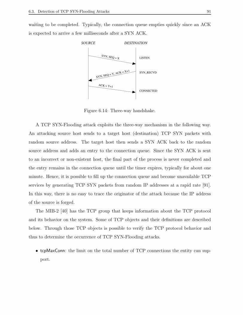
6.3. Detection of TCP SYN-Flooding Attacks 91
waiting to be completed. Typically, the connection queue empties quickly since an ACK
is expected to arrive a few milliseconds after a SYN ACK.
SOURCE DESTINATION
SYN_RECVD
LISTEN
CONNECTED
SYN, SEQ = Y, ACK = X+1
ACK = Y+1
SYN, SEQ = X
Figure 6.14: Three-way handshake.
A TCP SYN-Flooding attack exploits the three-way mechanism in the following way.
An attacking source host sends to a target host (destination) TCP SYN packets with
random source address. The target host then sends a SYN ACK back to the random
source address and adds an entry to the connection queue. Since the SYN ACK is sent
to an incorrect or non-existent host, the final part of the process is never completed and
the entry remains in the connection queue until the timer expires, typically for about one
minute. Hence, it is possible to fill up the connection queue and become unavailable TCP
services by generating TCP SYN packets from random IP addresses at a rapid rate [91].
In this way, there is no easy to trace the originator of the attack because the IP address
of the source is forged.
The MIB-2 [40] has the TCP group that keeps information about the TCP protocol
and its behavior on the system. Some of TCP objects and their definitions are described
below. Through those TCP objects is possible to verify the TCP protocol behavior and
thus to determine the occurrence of TCP SYN-Flooding attacks.
• tcpMaxConn: the limit on the total number of TCP connections the entity can sup-
port.

6.3. Detection of TCP SYN-Flooding Attacks 92
• tcpActiveOpens: the number of times TCP connections have made a direct transition
to the SYN-SENT state from the CLOSED state.
• tcpPassiveOpens: the number of times TCP connections have made a direct transition
to the SYN-RCVD state from the LISTEN state.
• tcpAttempFails: the number of times TCP connections have made a direct transition
to the CLOSED state from either the SYN-SENT state or the SYN-RCVD state, plus
the number of times TCP connections have made a direct transition to the LISTEN
state from the SYN-RCVD state.
• tcpEstabResets: the number of times TCP connections have made a direct transition
to the CLOSED state from either the ESTABLISHED state or the CLOSE-WAIT
state.
• tcpCurrEstab: the number of TCP connections for which the current state is either
ESTABLISHED or CLOSE-WAIT.
It is possible to get in [92] a description of the TCP finite state machine, which specifies
how a TCP protocol on one machine interacts with other TCP protocol.
Scenarios Description
An experiment was carried out at a local area network composed by machines based on
different Intel Pentium and AMD K6 processors, running Linux and connected through
a 100Mbps Ethernet LAN. The SNMP cluster managers were hosted in two machines
called genio and ork in order to monitor a subset of TCP managed objects. Each cluster
manager monitored a set of 12 machines and replicated TCP MIB objects to the other
cluster manager. A machine monitored by cluster genio was subjected to a TCP SYN-
Flooding attack [93], and after a few seconds, nearly 20 seconds, under the attack, it
crashed. The attack program used in our experiments was the Syn Flooder implemented
by Zakath [94].
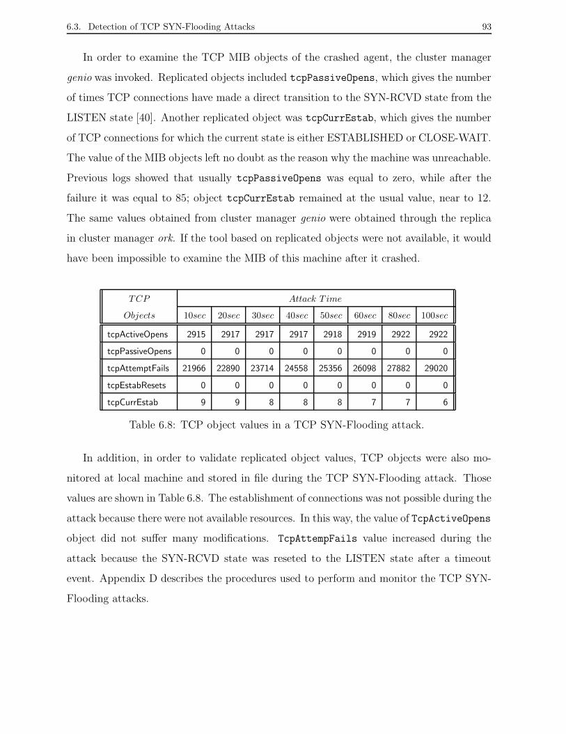
6.3. Detection of TCP SYN-Flooding Attacks 93
In order to examine the TCP MIB objects of the crashed agent, the cluster manager
genio was invoked. Replicated objects included tcpPassiveOpens, which gives the number
of times TCP connections have made a direct transition to the SYN-RCVD state from the
LISTEN state [40]. Another replicated object was tcpCurrEstab, which gives the number
of TCP connections for which the current state is either ESTABLISHED or CLOSE-WAIT.
The value of the MIB objects left no doubt as the reason why the machine was unreachable.
Previous logs showed that usually tcpPassiveOpens was equal to zero, while after the
failure it was equal to 85; object tcpCurrEstab remained at the usual value, near to 12.
The same values obtained from cluster manager genio were obtained through the replica
in cluster manager ork. If the tool based on replicated objects were not available, it would
have been impossible to examine the MIB of this machine after it crashed.
TCP Attack T ime
Objects 10sec 20sec 30sec 40sec 50sec 60sec 80sec 100sec
tcpActiveOpens 2915 2917 2917 2917 2918 2919 2922 2922
tcpPassiveOpens 0 0 0 0 0 0 0 0
tcpAttemptFails 21966 22890 23714 24558 25356 26098 27882 29020
tcpEstabResets 0 0 0 0 0 0 0 0
tcpCurrEstab 9 9 8 8 8 7 7 6
Table 6.8: TCP object values in a TCP SYN-Flooding attack.
In addition, in order to validate replicated object values, TCP objects were also mo-
nitored at local machine and stored in file during the TCP SYN-Flooding attack. Those
values are shown in Table 6.8. The establishment of connections was not possible during the
attack because there were not available resources. In this way, the value of TcpActiveOpens
object did not suffer many modifications. TcpAttempFails value increased during the
attack because the SYN-RCVD state was reseted to the LISTEN state after a timeout
event. Appendix D describes the procedures used to perform and monitor the TCP SYN-
Flooding attacks.
6.4. Conclusion 94
6.4 Conclusion
In this chapter, we presented a fault management tool based on the SNMP agent clustering
framework. The tool allows the construction of agent clusters for object replication. The
implementation of new functionalities within an SNMP agent allows ordinary SNMP agents
to play the role of cluster managers. A group communication infrastructure ensures reliable
communication among cluster managers. Thus, the replicated objects remain consistent
even in the presence of faults. We also described the procedure used to configure SNMP
agents as cluster managers.
We introduced an extensive evaluation of the tool carried out at a local area network. A
study of the network cost considered the space and bandwidth required to operate a cluster.
A performance analysis depicted the behavior of a cluster manager when monitoring several
subsets of objects. Further, the ability of mcluster application to multicast messages
for different sizes of peer clusters group was evaluated. Finally, an availability analysis
depicted the behavior of the communication between a cluster manager and its peer cluster
managers.
As a practical application of the tool, we presented how the tool can help to detect why
a given agent has crashed. An agent was subjected to TCP SYN-Flooding attack and next
values of its TCP objects were accessed in a cluster manager agent.
Chapter 7
Conclusions
This chapter presents the conclusions of the thesis. Section 7.1 describes the purpose and
expected results of this work. Section 7.2 describes the main contributions, and Section
7.3 presents possible applications and directions for future work.
7.1 Goals and Results
Network management systems include tools that enable monitoring and control of networks
composed by hardware, software, and heterogeneous protocols. In particular, network
management systems become essential during anomalous situations, when the network
is partly non-operational. Thus, fault management applications must be able to work
correctly even in the presence of network faults. Hence, it is important that network mana-
gement systems have a mechanism that allows the access to their management information
in numerous crash situations.
There is a vast literature on the construction of reliable distributed systems, and over
time the mechanisms to build reliable systems have improved and have been adapted to
new applications and environments. In Chapter 1, we presented some work related to the
development of reliable network and system management, presenting several approaches
and concepts to deal with the challenge of building fault-tolerant management systems.
95
7.2. Main Contributions 96
This thesis aggregated and adapted many of those solutions in order to develop a flexible
architecture based on agent clustering for replicating network management information,
and thus to provide the access to given management information of faulty management
entities. The architecture makes it possible to construct reliable network management
systems that are customized to the restrictions and the specific needs of a network. Par-
ticularly, this characteristic makes this work attractive since the approach may be used in
different kinds of networks. Moreover, this work considers issues such as the processing
capacity of management entities and the scalability of the system.
7.2 Main Contributions
The research of this thesis led to several research contributions such as the development
of a mechanism to build fault-tolerant network management systems, the specification of
an SNMP framework, the implementation and evaluation of a prototype, among others.
Those contributions are described below.
In the research, we have specified an architecture for agent clustering for managed
object replication. The architecture is structured in three layers called the cluster member
layer, the cluster layer, and the manager layer. The distributed three-tier architecture
provides scalability and flexibility for replicating different set of managed objects. Such
factors are fundamental for developing a fault-tolerant system. A cluster of agents provides
fault-tolerant object functionality by replicating managed objects among agent clusters.
Thus, it is possible to access managed objects of a crashed agent through peer clusters.
Furthermore, we have defined an SNMP framework for the agent clustering architec-
ture. The framework specifies SNMP management objects used for building SNMP agent
clusters, monitoring subsets of SNMP managed objects, and the storage and replication of
those objects values in SNMP agents called cluster managers. The MIB called Replic-MIB
introduces the usage of clusters and management objects to be implemented in each SNMP
entity of a network management system.
An SNMP fault management tool was built using public-domain software [22, 21]. The
7.3. Future Work and Applications 97
tool expands the functionalities of SNMP agents to play as cluster managers. A group com-
munication infrastructure under the cluster managers level ensures the consistency among
copies of managed objects values kept by cluster managers. An experimental evaluation
of the tool was carried out at a local area network. The evaluation showed the impact of
the configuration of clusters on network resource consumption and the tool performance.
An application example showed that the tool may be used to determine the occurrence of
DoS (Denial of Service) attacks.
An Internet-Draft in the Distributed Management (DisMan) Working Group of the
IETF describing the agent clustering architecture was published. The community has
discussed the proposed architecture as well as its application. Comments and suggestions
done during the IETF meetings have lead to new questions to be studied, for example,
the usage of a communication infrastructure using only SNMP operations. The discussion
of an Internet-Draft is a long process where the proposed work is commonly subjected to
many changes in its structure until the work can be published as a Request for Comments
(RFC) document, and thus to be adopted like a standard by the Internet community.
7.3 Future Work and Applications
Besides the contributions presented in the previous section, this research has raised many
interesting questions and issues that deserve further research. We give in the following a
series of suggestions and issues in order to improve the agent clustering architecture and
the usage of the SNMP fault monitoring tool.
The Monitoring tool in Three Layers
Our current SNMP monitoring tool only implements the simple compliance module de-
scribed in the SNMP agent clustering framework. This compliance module requires a
minimal set of management objects and does not take into account the management ob-
jects needed in the manager level. The next step is the development of the full framework

7.3. Future Work and Applications 98
that includes such management objects at the manager level. In this way, all cluster con-
figurations will be automatic and dynamic, and avoid the manual addition of configuration
files in the SNMP agents.
IETF Internet Standard
A number of challenges still exist to turn the Internet-Draft of the agent clustering ar-
chitecture in an Internet standard. Most of these challenges surround the issue of replica
consistency, and the factors that influence it. Important factors, such as reliable multicast
and group membership, currently provided by communication mechanisms like the Ensem-
ble system need to be handled under the point of view of the IETF standard. In the IETF,
working groups, such as Multicast & Anycast Group Membership (magma) [96], Reliable
Multicast Transport (rmt) [97], and Multicast Security (msec) [98], specify such group
services. Thus, it is necessary to check the applicability of those services to guarantee the
consistency of the MO’s replication provided by the agent clustering architecture. The tar-
get is to develop a version of the architecture totally in accordance with the other services
already specified by IETF so that it can be implemented by the Internet community.
Infrastructure Without Group Communication Toolkits
Many multicast and group membership protocols have been proposed in the literature for
different environments and targets [67, 64, 20, 21, 63, 99]. A simple multicast protocol and
a light weight group membership could be implemented in the SNMP agents to support the
communication among cluster managers. Hence, the fault monitoring tool would employ
no group communication toolkit. This would allow the development of a more flexible tool.
Aggregation of SNMP Managed Objects
The reduction of monitoring costs in the network management systems is an issue widely
discussed by the Internet community. In our agent clustering architecture, a cluster man-
ager must continuously monitor its agent members sending thus a number of queries. Those

7.3. Future Work and Applications 99
queries introduce bandwidth and processing overhead that contribute to constrain the num-
ber of MO’s that can be monitored. Mansfied-Keeni [87, 100] has proposed a strategy to
aggregate managed objects, and thus to reduce the number of queries sent to an SNMP
agent. The implementation of this strategy along with the agent clustering architecture
would enable the aggregation of objects monitored by a cluster manager in a few objects,
and would reduce the number of queries to agent members.
Reliable Detection of DDoS Attacks
A methodology for proactive detection of distributed denial of service (DDoS) attacks us-
ing network management systems has been proposed by Cabrera et al. [101]. The goal
of the methodology is to determine which MIB variables better characterize the occur-
rence of an attack in a given target machine, and so monitor such variables in order to
suppose anomalous behavior. The usage of the agent clustering architecture can enhance
this methodology, by enabling the development of reliable systems for detection of DDoS
attacks. In this way, DDoS attacks could be detected even if network elements suffering
the attack have failed.
Monitoring Communication Cost
The agent clustering architecture includes two functionalities to agents that play as cluster
manager: the abilities of monitoring and replicating managed objects. Particularly, the
monitoring ability is based on polling of agent members. This strategy introduces traffic
overhead and many times is not the better alternative to minimize the monitoring cost de-
pending on the characterization of the monitored data [2]. A possible solution to minimize
the monitoring communication cost is to combine polling with local event driven reporting.
Event reporting is a process where a local event in a network element triggers a report,
which is sent by that element to the manager. Thus, for example, agent members of a
cluster could report to the cluster manager when the values of certain objects would suffer
any update or reach a given value.
7.3. Future Work and Applications 100
Failure of Communication Links
The agent clustering architecture has taken into account the fail-stop model, which is
the simplest failure model. This failure model assumes reliable communication links and
that network components only fail by halting. However, such failure model may not be
realistic for different sorts of network as MANs and WANs, which are more prone to link
failures. For these kinds of networks, the omission model seems to be more adequate
since it considers the case of partitions and recovery of a network. Furthermore, such
model considers that components may fail during the execution of a given task, such as
the message transmission for all members of a group.
Considering communication link failures, it is important to determine which replica-
tion technique and communication mechanism must be applied when implementing the
agent clustering architecture in network management systems. In WANs, for example,
the probability of the occurrence of a large message delay is high. On the other hand,
group communication systems typically include membership protocols that assume that a
given component is faulty when a message delay happens. In general, such strategy can
take to mistakes and have a high processing cost. As a result of these suspects, a group
membership protocol would frequently create a new group view to exclude the component
suspected as faulty, and next it would create another group view to include this component
again [46].
Bibliography
[1] A. Leinwand and K. F. Conroy, Network Management: A Practical Perspective,
Addison-Wesley, 1996.
[2] M. Dilman and D. Raz, “Efficient Reactive Monitoring,” Proceedings of the IEEE
INFOCOM, Anchorage, AK, April 2001.
[3] D. Breitgand, G. Shaviner, and D. Dolev, “Towards Highly Available Three-Tier Mon-
itoring Applications,” Proceeding of the 11th IFIP/IEEE Workshop on Distributed
Systems: Operations & Management (DSOM’00) - Extended Abstract, Austin, Texas,
December 2000.
[4] D. Harrington, R. Presuhn, and B. Wijnen, “An Architecture for Describing SNMP
Management Frameworks,” RFC 3411, December 2002.
[5] J. Schonwalder, A. Pras, and J. P. Martin-Flatin, “On The Future of Internet Man-
agement Technologies,” IEEE Communications Magazines, Vol. 41, No. 10, pp. 90-97,
October 2003.
[6] Distributed Management (DisMan) Charter. Available at: http://www.ietf.org/html.
charters/disman-charter.html. Accessed October, 1999.
[7] R. Guerraoui and A. Schiper, “Fault-Tolerance by Replication in Distributed Sys-
tems,” International Conference on Reliable Software Technologies, Springer Verlag
(LNCS), 1996.
[8] R. Guerraoui and A. Schiper, “Software-based Replication for Fault Tolerance,” IEEE
Computer, Vol. 30, No. 4, pp. 68-74, April 1997.
101
Bibliography 102
[9] M. Wiesmann, F. Pedone, A. Schiper, B. Kemme, and G. Alonso, “Understanding
Replication in Databases and Distributed Systems,” Technical Report SSC/1999/035,
Ecole Polytechnique Federale de Lausanne, Switzerland, September 1999.
[10] M. Wiesmann, F. Pedone, A. Schiper, B. Kemme, and G. Alonso, “Database Replica-
tion Techniques: a Three Parameter Classification,” Proceedings of 19th IEEE Sympo-
sium on Reliable Distributed Systems (SRDS2000), pp. 206-215, Nurnberg, Germany,
October 2000.
[11] M. Wiesmann, Group Communications and Database Replication: Techniques, Issues
and Performance, Ph.D. Thesis, Ecole Polytechinque Federale de Lausanne, Lau-
sanne, 2002.
[12] K. Birman, Building Reliable and Secure Network Applications, Prentice-Hall, 1996.
[13] E. P. Duarte Jr., G. Mansfield, T. Nanya, and S. Noguchi, “Non-Broadcast Net-
work Fault-Monitoring Based on System-Level Diagnosis,” Proceedings of the 5th
IEEE/IFIP International Symposium on Integrated Network Management (IM’97),
San Diego CA, 1997.
[14] M. Bearden and R. Bianchini Jr., “Efficient and Fault-Tolerant Distributed Host Mon-
itoring Using System-Level Diagnosis,” Proceedings of the IFIP/IEEE International
Conference on Distributed Platforms, Dresden, Germany, pp. 159-172, February 1996.
[15] E. P. Duarte Jr., and T. Nanya, “A Hierarchical Adaptive Distributed System-Level
Diagnosis Algorithm,” IEEE Transactions on Computers, Vol. 47, No.1, pp. 34-45,
Jan 1998.
[16] S. Katker and M. Paterok, “Fault Isolation and Event Correlation for Integrated
Network Management,” Proceedings of the 5th IEEE/IFIP International Symposium
on Integrated Network Management (IM’97), San Diego CA, 1997.
[17] C. S. Hood, and C. Ji, “Proactive Network Fault Detection,” Proc. INFOCOM 97,
1997.
Bibliography 103
[18] W. Stallings, Snmp, Snmpv2, Snmpv3 and Rmon 1 and 2, Addison-Wesley, Reading,
MA, 1999.
[19] R. Sahner, K. S. Trivedi, and A. Puliafito, Performance and Reliability Analysis of
Computer Systems: An Example-Based ApproachUsing The SHARPE Software Pack-
age, Kluwer Academic Publishers, 1996.
[20] R. V. Renesse, K. P. Birman and S. Maffeis, “Horus: A Flexible Group Communication
System,” Communications of the ACM, Vol. 39, No. 4, pp. 76-83, April 1996.
[21] M. G. Hayden, The Ensemble System, Ph.D. Thesis, Cornell University, Ithaca, Jan.
1998.
[22] The NET-SNMP Home Page, Available at: http://net-snmp.sourceforge.net.
Accessed October, 2002.
[23] K.-H. Lee, “A Group Communication Protocol for Distributed Network Management
Systems,” In Proc. ICCC 95, pp. 363-368, 1995.
[24] J. Schonwalder, “Using Multicast-SNMP to Coordinate Distributed Management
Agents,” IEEE Workshop on Systems Management, June 1996.
[25] D. Breitgand, Group Communication as an Infrastructure for Distributed Systems
Management, Master Dissertation, Hebrew University of Jerusalem, June 1997.
[26] E. P. Duarte Jr. and A. L. dos Santos, “Semi-Active Replication of SNMP Objects
in Agent Groups Applied for Fault Management,” Proceedings of the 7th IFIP/IEEE
International Symposium on Integrated Network Management (IM’01), Seattle, May
2001.
[27] E. P. Duarte Jr. and A. L. dos Santos, “Network Fault Management Based on SNMP
Agent Groups,” Proceedings of the IEEE 21st International Conference on Distributed
Comput ing Systems Workshops (ICDCS’2001), Workshop on Applied Reliable Group
Communications, pp. 51-56, Mesa, Arizona, April 2001.
Bibliography 104
[28] W. Chen, N. Jain, and S. Singh, “ANMP: Ad Hoc Network Management Protocol,”
IEEE Journal on Selected Areas in Communications, Vol. 17, No. 8, August 1999.
[29] J. Wei, C. Shen, B. J. Wilson, and M. J. Post, “Network Control and Management
of a Reconfigurable WDM Network,” Proceedings of the Military Communications
Conference (MILCOM’96), Mclean, Virginia, October 1996.
[30] A. Pras, Network Management Architectures, Ph.D. Thesis, University of Twente,
Netherlands, 1995.
[31] W. Stallings, SNMP, SNMPv2, and CMIP. The Practical Guide to Network Manage-
ment Standards, Addison-Wesley, Reading, MA, 1993.
[32] M. T. Rose and K. McCloghrie, “Structure and Identification of Management Infor-
mation for TCP/IP-based Internets,” RFC 1155, Hughes LAN Systems, May 1990.
[33] J. D. Case, M.S. Fedor, M.L. ASchoffstall, and J.R. Davin, “A simple network man-
agement protocol,” RFC 1157, SNMP Research Inc., May 1990.
[34] K. McCloghrie, “SNMPv2 Management Information Base for the Internet Protocol
using SMIv2,” RFC 2011, Cisco Systems, November 1996.
[35] E. P. Duarte Jr., Fault-Tolerant Network Monitoring, Ph.D. Thesis, Tokyo Institute
of Technology, Tokyo, 1997.
[36] W. Stallings,“Network Management,” IEEE Computer Society Press, Los Alamitos,
CA, 1993.
[37] L. Steinberg, “Techniques for Managing Asynchronously Generated Alerts,” RFC
1224, IBM Corporation, May 1991.
[38] M. T. Rose, The Simple Book - An Introduction to Internet Management, 2nd ed.,
Prentice-Hall, Englewood Cliffs, NJ, 1996.
[39] McCloghrie, K., Perkins, D., Schoenwaelder, J., Case, J., Rose, M., and S. Waldbusser,
“Structure of Management Information Version 2 (SMIv2),” RFC 2578, April 1999.

Bibliography 105
[40] K. McCloghrie, “SNMPv2 Management Information Base for the Transmission Con-
trol Protocol using SMIv2,” RFC 2012, Cisco Systems, November 1996.
[41] K. McCloghrie, “SNMPv2 Management Information Base for the User Datagram Pro-
tocol using SMIv2,” RFC 2013, Cisco Systems, November 1996.
[42] J. P. Martin-Flatin, S. Znaty, and J. P. Hubaux, “A Survey of Distributed Enterprise
Network and Systems Management Paradigms,” Journal of Network and Systems
Management, 7(1), pp. 9-26, March 1999.
[43] J. P. Martin-Flatin, “Chapter 3: Two Taxonomies of Distributed Network and Systems
Management Paradigms,” Emerging Trends and Challenges in Network Management,
Plenum, March 2000.
[44] J. Schonwalder, “Evolution of Open Source SNMP Tools,” in Proc. SANE 2002 Con-
ference, May 2002.
[45] J. C. Laprie, “Dependability: Basic Concepts and Terminology,” Springer-Verlag,
Vienna, 1992.
[46] X. Defago, Agreement-Related Problems: from Semi-Passive Replication to Totally Or-
dered Broadcast, Ph.D. Thesis, Ecole Polytechinque Federale de Lausanne, Lausanne,
2000.
[47] V. Hadzilacos and S. Toueg, “Fault-Tolerant Broadcast and Related Problems,” In
S. Mullender, editor, Distributed Systems, ACM Press Books, Chapter 5, pp. 97-145,
Addison-Wesley, second edition, 1993.
[48] L. Lamport, R. Shostak, and M. Pease, “The Byzantine Generals Problem,” ACM
TOPLAS, Vol. 4, No. 3, pp. 382-401, July 1982.
[49] F. Cristian, H. Aghili, R. Strong, and D. Dolev, “Atomic Broadcast: From Simple
Message Diffusion to Byzantine Aggreement,” Proceedings of the 15th Symposium on
Fault-Tolerant Computing, pp. 200-206, June 1985.

Bibliography 106
[50] D. Powell, D. Seaton, G. Bonn, P. Verissimo, and F. Waeselynk, “The Delta-4 Ap-
proach to Dependability in Open Distributed Systems,” Proceedings of the IEEE 18th
International symposium on Fault-Tolerant Computing, Tokyo, June 1988.
[51] R. D. Schlichting and F. B. Schneider, “Fail-Stop Processor: An Approach to Design-
ing Fault Tolerant Computing Systems,” ACM Transactions on Computer Systems,
Vol. 3, No. 1, pp. 222-238, Aug. 1983.
[52] D. Powell, “Failure Mode Assumptions and Assumptions Coverage,” Proceedings of
the 22th IEEE Symposium on Fault-Tolerant Computing, pp. 386-395, 1992.
[53] N. Budhiraja, K. Marzullo, F. B. Schneider, and S. Toueg, “The Primary-Backup
Approach,” In S. Mullender, editor, Distributed Systems, ACM Press Books, Chapter
8, pp. 199-216, Addison-Wesley, second edition, 1993.
[54] K. P. Birman, T. Joseph, T. Raeuchle, and A. El Abbadi, “Implementing Fault-
Tolerant Distributed Objects,” IEEE Transactions on software Engineering, 11(6),
pp. 502-508, June 1985.
[55] K. Birman and R. van Renesse, Reliable Distributed Computing with the Isis Toolkit,
IEEE Computer Society Press, 1993.
[56] F. B. Schneider, “Implementing Fault-Tolerant Services Using The State Machine
Approach: A Tutorial,” ACM Computing Surveys, Vol. 22, No. 4, pp. 299-319, Dec.
1990.
[57] S. Poledna, “Replica Determinism in Distributed Real-Time Systems: A Brief Survey,”
Real-Times Sytems, 6(3), pp. 289-316, May 1994.
[58] T. D. Chandra and S. Toueg, “Unreliable Failure Detectors for Reliable Distributed
Systems,” Journal of the ACM, 43(2), pp. 225-267, 1996.
[59] X. Defago and A. Schiper, “Specification of Replication Techniques, Semi-Passive
Replication, and Lazy consensus,” Technical Report IC/2002/007, Ecole Polytech-
nique Federale de Lausanne, Switzerland, February 2002.

Bibliography 107
[60] D. Powell, “Delta-4: A Generic Architecture for Dependable Distributed Computing,”
ESPRIT Research Reports, Springer-Verlag, volume 1, 1991.
[61] K. Birman, “The Process Group Approach to Reliable Distributed Computing,” Com-
munications of the ACM, vol. 36, No. 12, pp. 37-53, December 1993.
[62] M. A. Hiltunem and R. D. Schlichting, “A Configurable Membership Service,” IEEE
Transactions on Computers, Vol. 47, No. 5, May 1998.
[63] S. Mishra, C. Fetzer and F. Cristian, “The Timewheel Group Membership Protocol,”
Proceedings of the 3rd IEEE Workshop on Fault-Tolerant Parallel and Distributed
Systems, Orlando, FL, April 1998.
[64] D. Dolev and D. Malki, “The Transis Approach to High Availability Cluster Commu-
nication,” Communications of the ACM, vol. 39, No. 4, pp. 64-70, December 1996.
[65] P. Felber, The CORBA Group Service: A Service Approach to Object Groups in
CORBA, Ph.D. Thesis, Ecole Polytechnique Federale de Lausanne, Switzerland, 1998.
[66] G. V. Chockler, I, Keidar, and R. Vitenberg, “Group Communication Specifications:
A Comprehensive Study,” ACM Computer Surveys, 33(4):143, December 2001.
[67] X. Defago, A. Schiper, and P. Urban, “Totally Ordered Broadcast and Multicast
Algorithms: A Comprehensive Survey,” Technical Report DSC/2000/036, Ecole Poly-
technique Federale de Lausanne, Switzerland, September 2000.
[68] D. Levi and J. Schonwalder, “Definitions of Managed Objects for the Delegation of
Management Scripts,” RFC 3165, August 2001.
[69] R. Kavasseri and B. Stewart, “Event MIB,” RFC 2981, October 2000.
[70] D. Levi and J. Schonwalder, “Definitions of Managed Objects for Scheduling Manage-
ment Operations,” RFC 3231, January 2002.
[71] S. Chisholm and D. Romascanu, “Alarm MIB,” Internet Draft, IETF, December 2001.
Bibliography 108
[72] A. L. dos Santos, E. P. Duarte Jr., and G. Mansfield, “Gerencia de Falhas Distribuıda e
Confiavel Baseada em Clusters de Agentes,” Proceedings of the XX Simposio Brasileiro
de Redes de Computadores (SBRC2002), Buzios, Rio de Janeiro, Maio 2002.
[73] A. L. dos Santos, E. P. Duarte Jr., and G. M. Keeni, “Reliable Distributed Network
Management by Replication,” Journal of Network and Systems Management, Vol. 12,
No. 2, June 2004.
[74] R. van Renesse, K, Birman, M. Hayden, A. Vaysburd, and D. Karr, “Building Adap-
tive Systems Using Ensemble,” Software-Practice and Experience, Vol. 28, No. 9, pp.
963-971, July 1998.
[75] M. Cukier, J. Ren, P. Rubel, D. E. Bakken, and D. A. Karr, “Building Dependable
Distributed Objects with the AQuA Architecture,” 29th Annual International Sym-
posium on Fault-Tolerant Computing (FTCS-29), Madison, Wiscosin, June 1999.
[76] M. Hayden and O. Rodeh, “Ensemble Tutorial”, The Ensemble Home Page, Available
at: http://www.cs.cornell.edu/Info/Prjects/Ensemble/doc/tut. Accessed November,
2001.
[77] J. Hickey, N. Lynch, and R. van Renesse, “Specifications and Proofs for Ensemble
Layers,” 5th International Conference on Tools and Algorithms for the Construction
and Analysis of Systems (TACAS), LNCS, Springer-Verlag, March 1999.
[78] Raj Jain, The Art of Computer System Performance Analysis, John Wiley & Sons,
1991.
[79] H. V. Ramasamy, P. Pandey, J. Lyons, M. Cukier, and W. H. Sanders, “Quantifying
the Cost of Providing Intrusion Tolerance in Group Communication Systems,” Pro-
cedings of the 2002 International Conference on Dependable Systems and Networks,
pp. 229-238, Washington, DC, June 2002.
[80] M. G. Merideth and P. Narasimhan, “Metrics for The Evaluation of Proactive and Re-
active Survivability,” Procedings of the 2003 International Conference on Dependable
Systems and Networks, San Francisco, CA, June 2003.
Bibliography 109
[81] C. Pattinson, “A Study of The Behaviour of The Simple Network Management Proto-
col,” Procedings of 12th International Workshop on Distributed Systems: Operations
& Management (DSOM’01), pp. 15-17, Nancy, France, October 2001.
[82] Y. Zhu, T. Chen S. Liu, “Models and Analysis of Trade-offs in Distributed Network
Management Approaches,” Proceedings of the 7th IFIP/IEEE International Sympo-
sium on Integrated Network Management (IM’01), pp. 391-404, Seattle, May 2001.
[83] J. Holliday, D. Agrawal, and E. Abbadi, “The Performance of Database Replication
with Group Multicast,” In Proc. FTCS 99, 1999.
[84] C. Basile, M. Killijian, and D. Powell, “A Survey of Dependability Issues in Mobile
Wireless Networks,” Technical Report, LAAS CNRS Toulouse, France, 2003.
[85] I. F. Akyildiz, W. Su, Y. Sankarasubramaniam, and E. Cayirci, “A Survey on Sensor
Networks,” IEEE Communications, Vol. 40, No. 8, pp. 102-114, 2002.
[86] J. Schonwalder, “SNMP Payload Compression,” Work In Progress, April 2001. Avail-
able at: http://www.ietf.org/internet-drafts/internet-draft/draft-irtf-nmrg-snmp-com
pression-01.txt
[87] G. M. Keeni, “The Managed Object Aggregation MIB,” Internet Draft, IETF,
September 2002. Available at:http://www.cysols.com/contrib/materials/draft-glenn-
mo-aggr-mib-02.txt
[88] Ensemble Home Page, Available at: http://www.cs.cornell.edu/Info/Projects/Ensemble
Accessed November, 2003.
[89] A. L. dos Santos, Avaliacao de Desempenho da Comunicacao com PVM em Ambiente
Linux, M.Sc. Dissertation, Federal University of Parana, May, 1999.
[90] C. L. Schuba, I. V. Krusul, M. G. Kuhn, E. H. Spafford, A. Sundaram, and D.
Zamboni, “Analysis of a Denial of Service Attack on TCP,” IEEE Symposium on
Security and Privacy, 1997.
Bibliography 110
[91] Cisco, Defining Strategies to Protect TCP SYN Denial of Service Attacks. Available
at: http://www.cisco.com/warp/public/707/4.pdf. Accessed June, 2000.
[92] D. E. Comer, D. L. Stevens, Internetworking with TCP/IP Volume II: Design, Imple-
mentation, and Internals, Prentice-Hall, 3rd edition, 1999.
[93] R. Farrow, “TCP SYN Flooding Attacks and Remedies,” Network Computing Unix
World. Available at: http://www.networkcomputing.com/unixworld/ security/004/0
04.txt.html. Accessed June, 2000.
[94] Operation: Security, Tools : Denial of Services - Syn Flooder by Zakath. Available
at: http://www.operationsecurity.com/resource db.php?viewCat=11. Accessed June,
2000.
[95] A. L. dos Santos, E. P. Duarte Jr., and G. Mansfield, “A Clustering Architecture for
Replicating Managed Objects,” Internet Draft, IETF, November 2001. Available at:
http://www.inf.ufpr.br/∼aldri/draft/replicationmib/index.html
[96] Multicast & Anycast Group Membership (magma) Charter, Available at: http://www.
ietf.org/html.charters/magma-charter.html, Accessed October, 2003.
[97] Reliable Multicast Transport (rmt) Charter, Available at: http://www.ietf.org/html.
charters/rmt-charter.html, Accessed October, 2003.
[98] Multicast Security (msec) Charter, Available at: http://www.ietf.org/html.charters/
msec-charter.html, Accessed October, 2003.
[99] M. Raynal and F. Tronel, “Group Membership Failure Detection: A Simple Protocol
and Its Probability Analysis,” Distributed Systems Engineering Journal, 6(3), pp. 95-
102, 1999.
[100] G. M. Keeni, “The Aggregation MIB for Time Based Samples of A Managed Object,”
Internet Draft, IETF, September 2002. Available at: http://www.cysols.com/contrib
/materials/draft-glenn-mo-taggr-mib-00.txt
Bibliography 111
[101] J. B. Cabrera, L. Lewis, X. Qin, W. Lee, R. Prasanth, B. Ravichandran, and Ra-
man Mehra,“Proactive Detection of Distributed Denial of Service Attacks Using MIB
Variables - A Feasibility Study,” Proceedings of the 7th IFIP/IEEE International Sym-
posium on Integrated Network Management (IM’01), Seattle, May 2001.
[102] “The Internet Engineering Task Force (IETF),” The Tao of IETF: A Novice’s Gui-
de to the Internet Engineering Task Force. Available at: http://www.ietf.org/tao.html
#6.3. Acessed March, 2004.
[103] J. Postel and J. Reynolds, “Intructions to RFC Authors,” RFC 2223, ISI, October
1997.
[104] S. Bradner, “The Internet Standards Process – Revision 3,” RFC 2026, Harvard
University, October 1996.
[105] C. Huitema, J. Postel, and S. Crocker, “Not All RFCs are Standards,”, RFC 1796,
April 1995.

Appendix A
Replication MIB
This appendix presents the complete design of the Replication MIB. Next, we present an
overview of the steps required to publish an RFC document at the Internet Engineering
Task Force (IETF).
1. REPLIC-MIB
REPLIC-MIB DEFINITIONS ::= BEGIN
IMPORTS
MODULE-IDENTITY, OBJECT-TYPE,
Unsigned32, enterprises
FROM SNMPv2-SMI
RowStatus, TimeStamp
FROM SNMPv2-TC
MODULE-COMPLIANCE, OBJECT-GROUP
FROM SNMPv2-CONF
InetAddressType, InetAddress
FROM INET-ADDRESS-MIB
SnmpAdminString
FROM SNMP-FRAMEWORK-MIB;
112
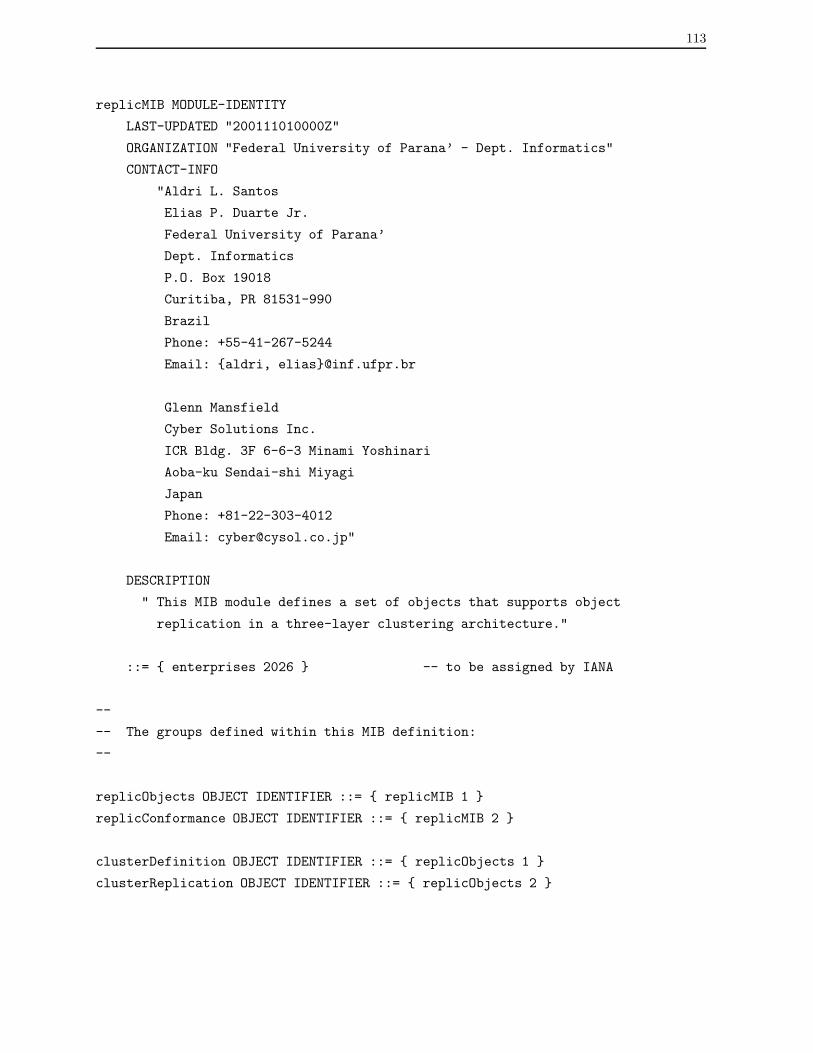
113
replicMIB MODULE-IDENTITY
LAST-UPDATED "200111010000Z"
ORGANIZATION "Federal University of Parana’ - Dept. Informatics"
CONTACT-INFO
"Aldri L. Santos
Elias P. Duarte Jr.
Federal University of Parana’
Dept. Informatics
P.O. Box 19018
Curitiba, PR 81531-990
Brazil
Phone: +55-41-267-5244
Email: {aldri, elias}@inf.ufpr.br
Glenn Mansfield
Cyber Solutions Inc.
ICR Bldg. 3F 6-6-3 Minami Yoshinari
Aoba-ku Sendai-shi Miyagi
Japan
Phone: +81-22-303-4012
Email: [email protected]"
DESCRIPTION
" This MIB module defines a set of objects that supports object
replication in a three-layer clustering architecture."
::= { enterprises 2026 } -- to be assigned by IANA
--
-- The groups defined within this MIB definition:
--
replicObjects OBJECT IDENTIFIER ::= { replicMIB 1 }
replicConformance OBJECT IDENTIFIER ::= { replicMIB 2 }
clusterDefinition OBJECT IDENTIFIER ::= { replicObjects 1 }
clusterReplication OBJECT IDENTIFIER ::= { replicObjects 2 }

114
clusterTable OBJECT-TYPE
SYNTAX SEQUENCE OF ClusterEntry
MAX-ACCESS not-accessible
STATUS current
DESCRIPTION
" This table allows the definition of agent clusters, which
are used to monitor and replicate objects from other agents,
providing alternative means of accessing information from
those agents when they are unreachable."
::= { clusterDefinition 1 }
clusterEntry OBJECT-TYPE
SYNTAX ClusterEntry
MAX-ACCESS not-accessible
STATUS current
DESCRIPTION
" Each entry contains the definition of an agent cluster, its
members and replicated objects."
INDEX { clusterID, clusterIndex }
::= { clusterTable 1 }
ClusterEntry ::= SEQUENCE {
clusterIndex Unsigned32,
clusterID Unsigned32,
clusterAddressType InetAddressType,
clusterAddress InetAddress,
clusterMemberType InetAddressType,
clusterMember InetAddress,
clusterOID OBJECT IDENTIFIER,
clusterInstanceIndex OBJECT IDENTIFIER,
clusterRepClusterID Unsigned32,
clusterName SnmpAdminString,
clusterDescr SnmpAdminString,
clusterStatus RowStatus
}
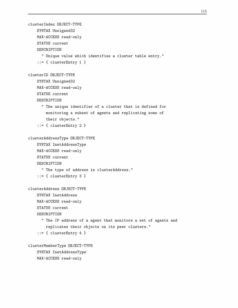
115
clusterIndex OBJECT-TYPE
SYNTAX Unsigned32
MAX-ACCESS read-only
STATUS current
DESCRIPTION
" Unique value which identifies a cluster table entry."
::= { clusterEntry 1 }
clusterID OBJECT-TYPE
SYNTAX Unsigned32
MAX-ACCESS read-only
STATUS current
DESCRIPTION
" The unique identifier of a cluster that is defined for
monitoring a subset of agents and replicating some of
their objects."
::= { clusterEntry 2 }
clusterAddressType OBJECT-TYPE
SYNTAX InetAddressType
MAX-ACCESS read-only
STATUS current
DESCRIPTION
" The type of address in clusterAddress."
::= { clusterEntry 3 }
clusterAddress OBJECT-TYPE
SYNTAX InetAddress
MAX-ACCESS read-only
STATUS current
DESCRIPTION
" The IP address of a agent that monitors a set of agents and
replicates their objects on its peer clusters."
::= { clusterEntry 4 }
clusterMemberType OBJECT-TYPE
SYNTAX InetAddressType
MAX-ACCESS read-only

116
STATUS current
DESCRIPTION
" The type of address in clusterMember."
::= { clusterEntry 5 }
clusterMember OBJECT-TYPE
SYNTAX InetAddress
MAX-ACCESS read-only
STATUS current
DESCRIPTION
" The IP address of an agent which has its objects monitored
and replicated by the cluster."
::= { clusterEntry 6 }
clusterOID OBJECT-TYPE
SYNTAX OBJECT IDENTIFIER
MAX-ACCESS read-only
STATUS current
DESCRIPTION
" The instance identifier of a replicated managed object.
For example: ifInOctets "
::= { clusterEntry 7 }
clusterInstanceIndex OBJECT-TYPE
SYNTAX OBJECT IDENTIFIER
MAX-ACCESS read-only
STATUS current
DESCRIPTION
" Unique identifier of an instance index of a replicated
managed object."
::= { clusterEntry 8 }
clusterRepClusterID OBJECT-TYPE
SYNTAX Unsigned32
MAX-ACCESS read-only
STATUS current
DESCRIPTION
" Identifier of a peer cluster which keeps replica of managed
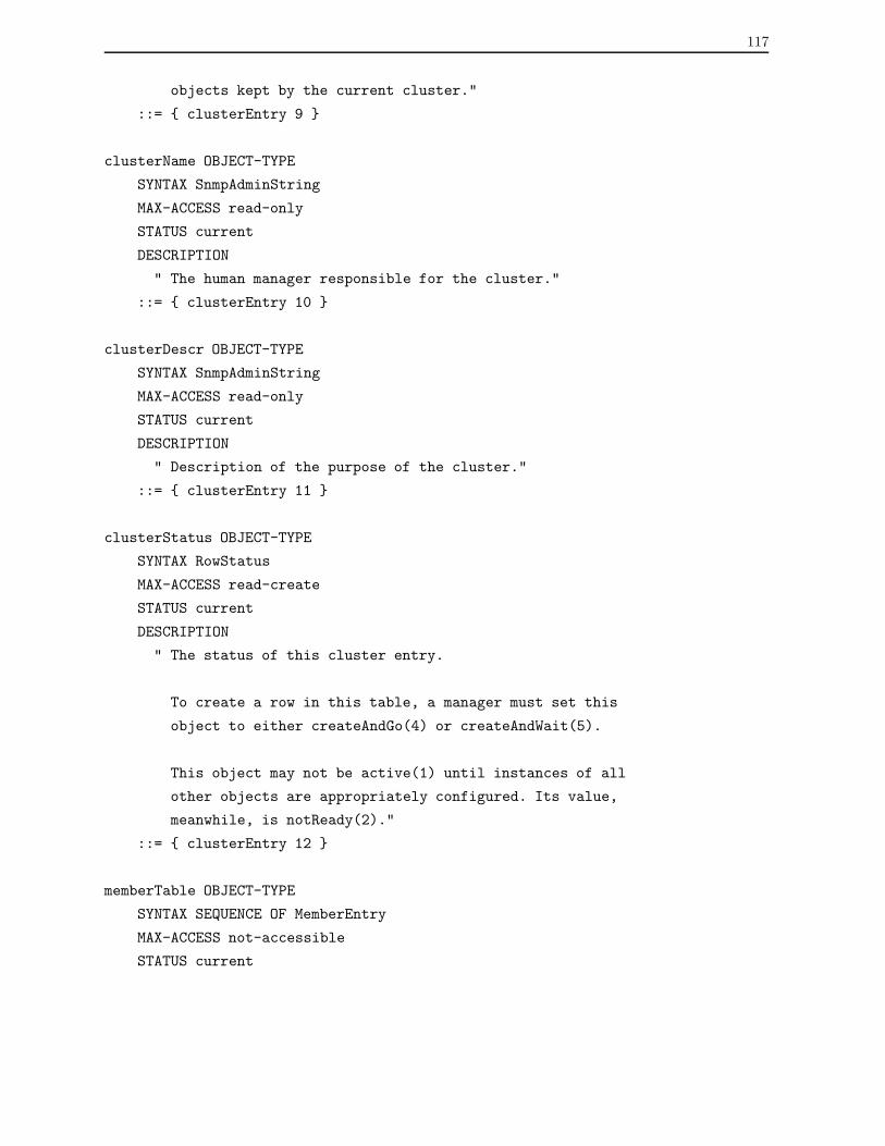
117
objects kept by the current cluster."
::= { clusterEntry 9 }
clusterName OBJECT-TYPE
SYNTAX SnmpAdminString
MAX-ACCESS read-only
STATUS current
DESCRIPTION
" The human manager responsible for the cluster."
::= { clusterEntry 10 }
clusterDescr OBJECT-TYPE
SYNTAX SnmpAdminString
MAX-ACCESS read-only
STATUS current
DESCRIPTION
" Description of the purpose of the cluster."
::= { clusterEntry 11 }
clusterStatus OBJECT-TYPE
SYNTAX RowStatus
MAX-ACCESS read-create
STATUS current
DESCRIPTION
" The status of this cluster entry.
To create a row in this table, a manager must set this
object to either createAndGo(4) or createAndWait(5).
This object may not be active(1) until instances of all
other objects are appropriately configured. Its value,
meanwhile, is notReady(2)."
::= { clusterEntry 12 }
memberTable OBJECT-TYPE
SYNTAX SEQUENCE OF MemberEntry
MAX-ACCESS not-accessible
STATUS current

118
DESCRIPTION
" This table contains information that defines the set of
agents monitored by the cluster."
::={ clusterDefinition 2 }
memberEntry OBJECT-TYPE
SYNTAX MemberEntry
MAX-ACCESS not-accessible
STATUS current
DESCRIPTION
" Each entry contains the definition of a cluster member."
INDEX { cmIndex }
::= { memberTable 1 }
MemberEntry ::= SEQUENCE {
cmIndex Unsigned32,
cmAddressType InetAddressType,
cmAddress InetAddress,
cmSecurity SnmpAdminString,
cmStatus RowStatus
}
cmIndex OBJECT-TYPE
SYNTAX Unsigned32
MAX-ACCESS read-only
STATUS current
DESCRIPTION
" Unique identifier of a cluster member table entry."
::= { memberEntry 1 }
cmAddressType OBJECT-TYPE
SYNTAX InetAddressType
MAX-ACCESS read-only
STATUS current
DESCRIPTION
" The type of address in cmAddress."
::= { memberEntry 2 }

119
cmAddress OBJECT-TYPE
SYNTAX InetAddress
MAX-ACCESS read-only
STATUS current
DESCRIPTION
" The IP address of a cluster member whose objects are
monitored and replicated by the cluster."
::= { memberEntry 3 }
cmSecurity OBJECT-TYPE
SYNTAX SnmpAdminString
MAX-ACCESS read-only
STATUS current
DESCRIPTION
" The security required to access cluster member objects."
::= { memberEntry 4 }
cmStatus OBJECT-TYPE
SYNTAX RowStatus
MAX-ACCESS read-create
STATUS current
DESCRIPTION
" The status of this cluster member entry.
To create a row in this table, a manager must set this
object to either createAndGo(4) or createAndWait(5).
This object may not be active(1) until instances of all
other objects are appropriately configured. Its value,
meanwhile, is notReady(2)."
::= { memberEntry 5 }
repObjectTable OBJECT-TYPE
SYNTAX SEQUENCE OF RepObjectEntry
MAX-ACCESS not-accessible
STATUS current
DESCRIPTION
" This table allows the definition of a set of managed objects
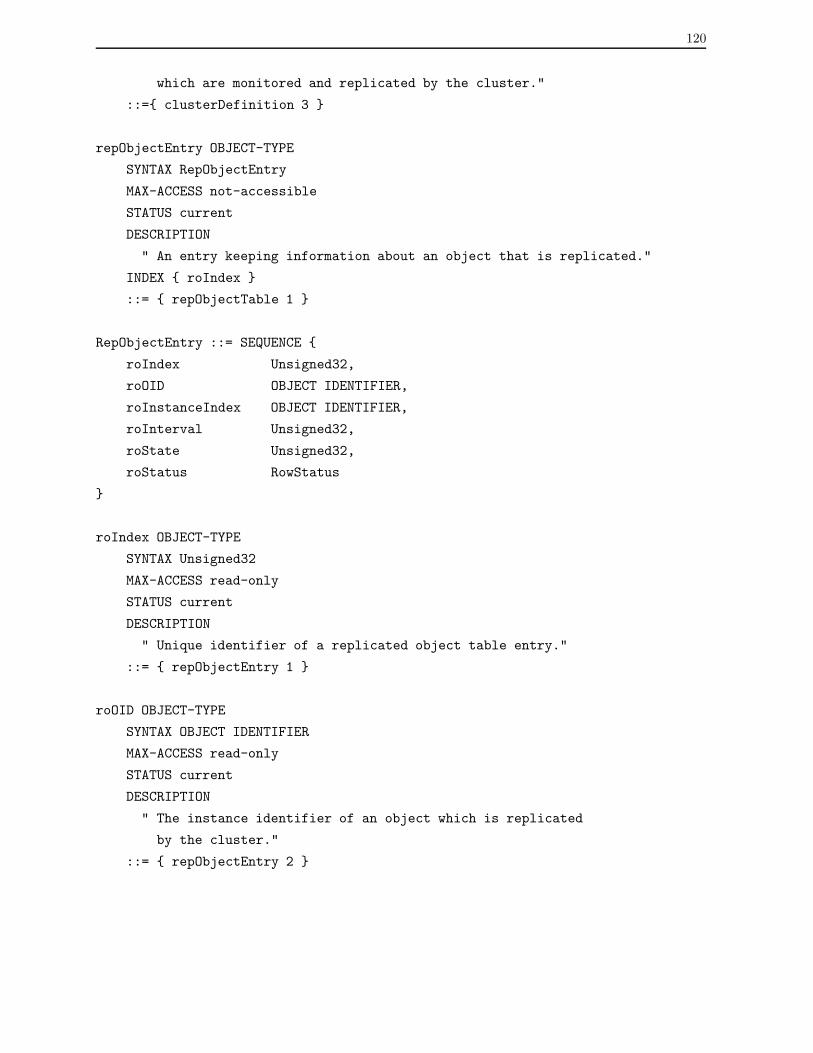
120
which are monitored and replicated by the cluster."
::={ clusterDefinition 3 }
repObjectEntry OBJECT-TYPE
SYNTAX RepObjectEntry
MAX-ACCESS not-accessible
STATUS current
DESCRIPTION
" An entry keeping information about an object that is replicated."
INDEX { roIndex }
::= { repObjectTable 1 }
RepObjectEntry ::= SEQUENCE {
roIndex Unsigned32,
roOID OBJECT IDENTIFIER,
roInstanceIndex OBJECT IDENTIFIER,
roInterval Unsigned32,
roState Unsigned32,
roStatus RowStatus
}
roIndex OBJECT-TYPE
SYNTAX Unsigned32
MAX-ACCESS read-only
STATUS current
DESCRIPTION
" Unique identifier of a replicated object table entry."
::= { repObjectEntry 1 }
roOID OBJECT-TYPE
SYNTAX OBJECT IDENTIFIER
MAX-ACCESS read-only
STATUS current
DESCRIPTION
" The instance identifier of an object which is replicated
by the cluster."
::= { repObjectEntry 2 }
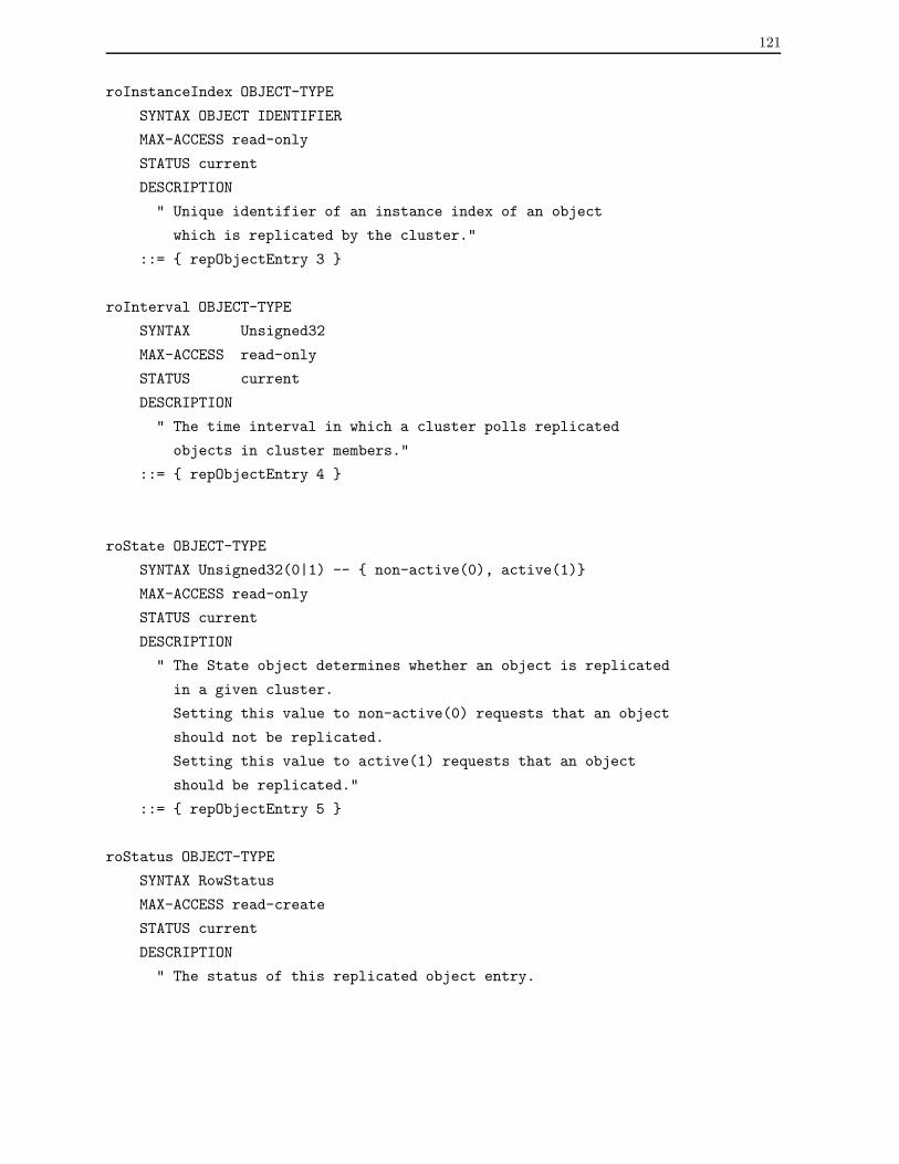
121
roInstanceIndex OBJECT-TYPE
SYNTAX OBJECT IDENTIFIER
MAX-ACCESS read-only
STATUS current
DESCRIPTION
" Unique identifier of an instance index of an object
which is replicated by the cluster."
::= { repObjectEntry 3 }
roInterval OBJECT-TYPE
SYNTAX Unsigned32
MAX-ACCESS read-only
STATUS current
DESCRIPTION
" The time interval in which a cluster polls replicated
objects in cluster members."
::= { repObjectEntry 4 }
roState OBJECT-TYPE
SYNTAX Unsigned32(0|1) -- { non-active(0), active(1)}
MAX-ACCESS read-only
STATUS current
DESCRIPTION
" The State object determines whether an object is replicated
in a given cluster.
Setting this value to non-active(0) requests that an object
should not be replicated.
Setting this value to active(1) requests that an object
should be replicated."
::= { repObjectEntry 5 }
roStatus OBJECT-TYPE
SYNTAX RowStatus
MAX-ACCESS read-create
STATUS current
DESCRIPTION
" The status of this replicated object entry.

122
To create a row in this table, a manager must set this
object to either createAndGo(4) or createAndWait(5).
This object may not be active(1) until instances of all
other objects are appropriately configured. Its value,
meanwhile, is notReady(2)."
::= { repObjectEntry 6 }
peerTable OBJECT-TYPE
SYNTAX SEQUENCE OF PeerEntry
MAX-ACCESS not-accessible
STATUS current
DESCRIPTION
" This table allows the definition of peer clusters of agent
clusters which are used to maintain replicated objects."
::={ clusterDefinition 4 }
peerEntry OBJECT-TYPE
SYNTAX PeerEntry
MAX-ACCESS not-accessible
STATUS current
DESCRIPTION
" Each entry contains information of a cluster that maintains
replicated objects."
INDEX { pcIndex }
::= { peerTable 1 }
PeerEntry ::= SEQUENCE {
pcIndex Unsigned32,
pcAddressType InetAddressType,
pcAddress InetAddress,
pcROTIndex Unsigned32,
pcStatus RowStatus
}
pcIndex OBJECT-TYPE
SYNTAX Unsigned32
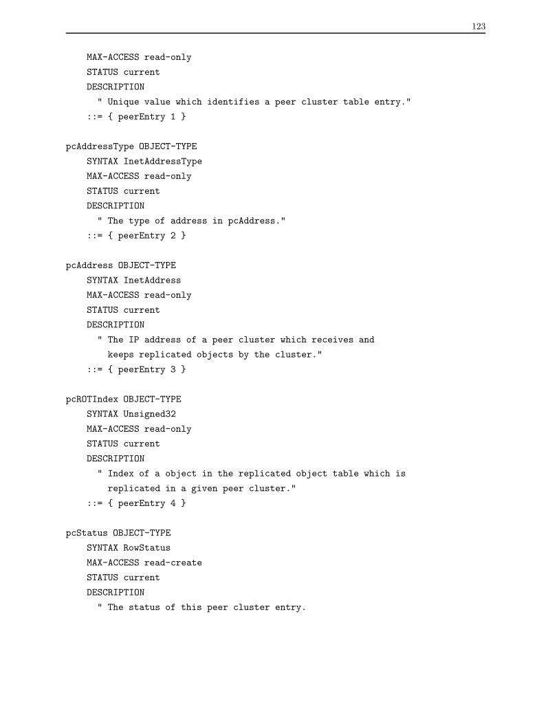
123
MAX-ACCESS read-only
STATUS current
DESCRIPTION
" Unique value which identifies a peer cluster table entry."
::= { peerEntry 1 }
pcAddressType OBJECT-TYPE
SYNTAX InetAddressType
MAX-ACCESS read-only
STATUS current
DESCRIPTION
" The type of address in pcAddress."
::= { peerEntry 2 }
pcAddress OBJECT-TYPE
SYNTAX InetAddress
MAX-ACCESS read-only
STATUS current
DESCRIPTION
" The IP address of a peer cluster which receives and
keeps replicated objects by the cluster."
::= { peerEntry 3 }
pcROTIndex OBJECT-TYPE
SYNTAX Unsigned32
MAX-ACCESS read-only
STATUS current
DESCRIPTION
" Index of a object in the replicated object table which is
replicated in a given peer cluster."
::= { peerEntry 4 }
pcStatus OBJECT-TYPE
SYNTAX RowStatus
MAX-ACCESS read-create
STATUS current
DESCRIPTION
" The status of this peer cluster entry.
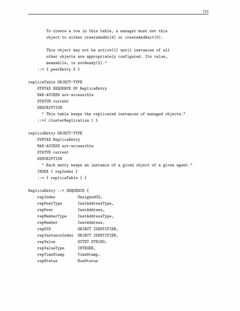
124
To create a row in this table, a manager must set this
object to either createAndGo(4) or createAndWait(5).
This object may not be active(1) until instances of all
other objects are appropriately configured. Its value,
meanwhile, is notReady(2)."
::= { peerEntry 5 }
replicaTable OBJECT-TYPE
SYNTAX SEQUENCE OF ReplicaEntry
MAX-ACCESS not-accessible
STATUS current
DESCRIPTION
" This table keeps the replicated instances of managed objects."
::={ clusterReplication 1 }
replicaEntry OBJECT-TYPE
SYNTAX ReplicaEntry
MAX-ACCESS not-accessible
STATUS current
DESCRIPTION
" Each entry keeps an instance of a given object of a given agent."
INDEX { repIndex }
::= { replicaTable 1 }
ReplicaEntry ::= SEQUENCE {
repIndex Unsigned32,
repPeerType InetAddressType,
repPeer InetAddress,
repMemberType InetAddressType,
repMember InetAddress,
repOID OBJECT IDENTIFIER,
repInstanceIndex OBJECT IDENTIFIER,
repValue OCTET STRING,
repValueType INTEGER,
repTimeStamp TimeStamp,
repStatus RowStatus

125
}
repIndex OBJECT-TYPE
SYNTAX Unsigned32
MAX-ACCESS read-only
STATUS current
DESCRIPTION
" Unique value which identifies a replica table entry."
::= { replicaEntry 1 }
repPeerType OBJECT-TYPE
SYNTAX InetAddressType
MAX-ACCESS read-only
STATUS current
DESCRIPTION
" The type of address in repPeer."
::= { replicaEntry 2 }
repPeer OBJECT-TYPE
SYNTAX InetAddress
MAX-ACCESS read-only
STATUS current
DESCRIPTION
" The IP address of a peer cluster that monitors a set of
agents and replicates their objects in the cluster."
::= { replicaEntry 3 }
repMemberType OBJECT-TYPE
SYNTAX InetAddressType
MAX-ACCESS read-only
STATUS current
DESCRIPTION
" The type of address in repMember."
::= { replicaEntry 4 }
repMember OBJECT-TYPE
SYNTAX IpAddress
MAX-ACCESS read-only
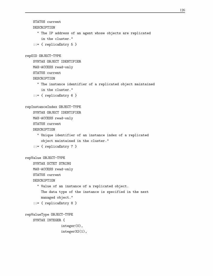
126
STATUS current
DESCRIPTION
" The IP address of an agent whose objects are replicated
in the cluster."
::= { replicaEntry 5 }
repOID OBJECT-TYPE
SYNTAX OBJECT IDENTIFIER
MAX-ACCESS read-only
STATUS current
DESCRIPTION
" The instance identifier of a replicated object maintained
in the cluster."
::= { replicaEntry 6 }
repInstanceIndex OBJECT-TYPE
SYNTAX OBJECT IDENTIFIER
MAX-ACCESS read-only
STATUS current
DESCRIPTION
" Unique identifier of an instance index of a replicated
object maintained in the cluster."
::= { replicaEntry 7 }
repValue OBJECT-TYPE
SYNTAX OCTET STRING
MAX-ACCESS read-only
STATUS current
DESCRIPTION
" Value of an instance of a replicated object.
The data type of the instance is specified in the next
managed object."
::= { replicaEntry 8 }
repValueType OBJECT-TYPE
SYNTAX INTEGER {
integer(0),
integer32(1),

127
unsigned32(2),
gauge32(3),
counter32(4),
counter64(5),
timeTicks(6),
octectString(7),
objectIdentifier(8),
ipAddress(9),
opaque(10),
bits(11)
}
MAX-ACCESS read-only
STATUS current
DESCRIPTION
" The data type of an instance of a replicated object kept
in the previous managed object."
::= { replicaEntry 9 }
repTimeStamp OBJECT-TYPE
SYNTAX TimeStamp
MAX-ACCESS read-only
STATUS current
DESCRIPTION
" The value of sysUpTime at the time of the last update
of a value of an instance of a replicated object."
::= { replicaEntry 10 }
repStatus OBJECT-TYPE
SYNTAX RowStatus
MAX-ACCESS read-create
STATUS current
DESCRIPTION
" The status of this replica entry.
This object may not be active(1) until instances of all
other objects are appropriately configured. Its value,
meanwhile, is notReady(2)."
::= { replicaEntry 11 }

128
-- Conformance information
replicGroups OBJECT IDENTIFIER ::= { replicConformance 1 }
replicCompliances OBJECT IDENTIFIER ::= { replicConformance 2 }
-- Compliance statements
replicManagerCompliance MODULE-COMPLIANCE
STATUS current
DESCRIPTION
" The compliance statement for SNMP entities which
implement the replication MIB in the manager level."
MODULE
MANDATORY-GROUPS { replicManagerGroup }
::= { replicCompliances 1 }
replicClusterCompliance MODULE-COMPLIANCE
STATUS current
DESCRIPTION
" The compliance statement for SNMP entities which
implement the replication MIB in the cluster level."
MODULE
MANDATORY-GROUPS { replicClusterGroup }
::= { replicCompliances 2 }
replicFullCompliance MODULE-COMPLIANCE
STATUS current
DESCRIPTION
" The compliance statement for SNMP entities which
implement the replication MIB in three layers."
MODULE
MANDATORY-GROUPS { replicManagerGroup, replicClusterGroup }
::= { replicCompliances 3 }
-- Units of conformance
replicManagerGroup OBJECT-GROUP
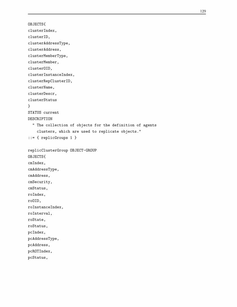
129
OBJECTS{
clusterIndex,
clusterID,
clusterAddressType,
clusterAddress,
clusterMemberType,
clusterMember,
clusterOID,
clusterInstanceIndex,
clusterRepClusterID,
clusterName,
clusterDescr,
clusterStatus
}
STATUS current
DESCRIPTION
" The collection of objects for the definition of agents
clusters, which are used to replicate objects."
::= { replicGroups 1 }
replicClusterGroup OBJECT-GROUP
OBJECTS{
cmIndex,
cmAddressType,
cmAddress,
cmSecurity,
cmStatus,
roIndex,
roOID,
roInstanceIndex,
roInterval,
roState,
roStatus,
pcIndex,
pcAddressType,
pcAddress,
pcROTIndex,
pcStatus,
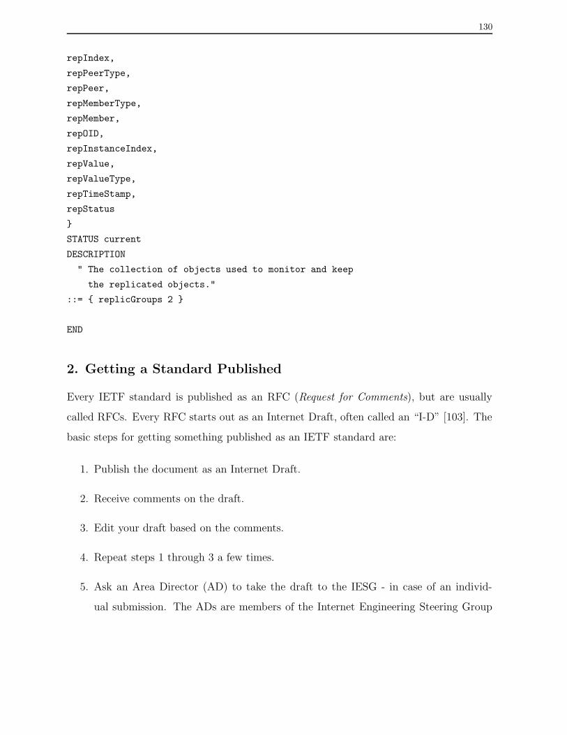
130
repIndex,
repPeerType,
repPeer,
repMemberType,
repMember,
repOID,
repInstanceIndex,
repValue,
repValueType,
repTimeStamp,
repStatus
}
STATUS current
DESCRIPTION
" The collection of objects used to monitor and keep
the replicated objects."
::= { replicGroups 2 }
END
2. Getting a Standard Published
Every IETF standard is published as an RFC (Request for Comments), but are usually
called RFCs. Every RFC starts out as an Internet Draft, often called an “I-D” [103]. The
basic steps for getting something published as an IETF standard are:
1. Publish the document as an Internet Draft.
2. Receive comments on the draft.
3. Edit your draft based on the comments.
4. Repeat steps 1 through 3 a few times.
5. Ask an Area Director (AD) to take the draft to the IESG - in case of an individ-
ual submission. The ADs are members of the Internet Engineering Steering Group
131
(IESG). When the draft is an official working group (WG) product, the WG chair
asks the AD to take it to the IESG. To understand the IETF hierarchy, see [102].
6. Make any changes deemed necessary by the IESG, and this might include giving up
on becoming a standard.
7. Wait for the document to be published by the RFC Editor.
A complete explanation of these steps is contained in “The Internet Standards Pro-
cess”, RFC 2026 [104]. This RFC goes into great detail on a topic that is very often
misunderstood, even by seasoned IETF participants: different types of RFCs go through
different processes and have different rankings. There are six kinds of RFCs:
• Proposed standards
• Draft standards
• Internet standards, sometimes called “full standards”
• Experimental protocols
• Informational documents
• Historic standards
Only the first three (proposed, draft, and full) are standards within the IETF. A sum-
mary of the RFCs classification can be found in “Not All RFCs are Standards”, RFC 1796
[105].
There are also three sub-series of RFCs, known as FYIs, BCPs, and STDs. The For
Your Information (FYI) RFC sub-series was created to document overviews and topics
which are introductory or appeal to a broad audience. Frequently, FYIs are created by
groups within the IETF User Services Area. Best Current Practice (BCP) documents
describe the application of various technologies in the Internet. The STD RFC sub-series
was created to identify RFCs that do in fact specify Internet standards. Some STDs are

132
actually sets of more than one RFC, and the standard designation applies to the whole set
of documents.
The main reason some people do not want their documents put on the IETF standards
track is that they must give up change control on their work. That is, as soon as people
propose that their work become an IETF standard, they must fully relinquish control on
it. If there is general agreement, parts of the document can be completely changed, whole
sections can be ripped out, new ideas can be added, and the name can be changed. On
the other hand, if the goal is the best standard possible with the widest implementation,
then the IETF process looks like to be an adequate place.
Incidentally, the change control on Internet standards does not end when the work is put
on the standards track. The document itself can be changed later for a number of reasons,
the most common of which is that developers discover a problem as they implement the
standard. These later changes are also under the control of the IETF, not the editors of
the standards document.

Appendix B
Usage of the SNMP Tool
This appendix presents the usage of the SNMP fault management tool based on the SNMP
agent clustering framework. The manual below shows how to specify the agent members,
the replicated objects, and the peer clusters of a cluster. Particularly, it describes a full
example of clusters configuration and exhibits the management information displayed by
the tool. The host names and IP addresses mentioned over the text belong to laboratories
of Department of Informatics of UFPR.
1. Defining Clusters
This example configuration defines two clusters identified by the dupont and tournesol
cluster managers. The IP addresses of the network elements that host the dupont and
tournesol clusters are 200.17.212.160 and 200.17.212.159, respectively.
The dupont cluster has two agent members called chef and cartman. Those agents
are hosted in the machines whose IP addresses are 200.17.212.117 and 200.17.102.160,
respectively. The dupont cluster will monitor a set of seven objects of the ICMP group.
These objects will be replicated at the dupont local MIB and in the tournesol cluster,
which is its peer cluster. The configuration files that define the dupont cluster are shown
below, and the tournesol cluster is described in sequence.
133

134
Arguments of the dupont.ClusterMembers.conf file:
#INDEX IP ADDRESS PORT SECURITY STATUS
10 chef 5000 public 1
20 cartman 5000 public 1
Arguments of the dupont.ReplicatedObjects.conf file:
#INDEX OID OID INDEX INTERVAL STATE STATUS
1 .1.3.6.1.2.1.5.1 0 10 1 1
2 .1.3.6.1.2.1.5.2 0 10 1 1
3 .1.3.6.1.2.1.5.4 0 10 1 1
4 .1.3.6.1.2.1.5.8 0 10 1 1
5 .1.3.6.1.2.1.5.14 0 10 1 1
6 .1.3.6.1.2.1.5.16 0 10 1 1
7 .1.3.6.1.2.1.5.22 0 10 1 1
Arguments dupont.PeerCluster.conf file:
#INDEX IP ADDRESS ROTINDEX STATUS
1 tournesol 1 1
2 tournesol 2 1
3 tournesol 3 1
4 tournesol 4 1
5 tournesol 5 1
6 tournesol 6 1
7 tournesol 7 1
The tournesol cluster has two agent members called shelley and wendy, and whose
IP addresses are 200.17.212.95 and 200.17.212.125, respectively. The tournesol cluster
will monitor three objects of the ICMP group. Those objects will be replicated in the
tournesol local MIB, and in the dupont cluster, which is the peer cluster. The configu-
ration files that define the tournesol cluster are shown below.
Arguments of the tournesol.ClusterMembers.conf file:
#INDEX IP ADDRESS PORT SECURITY STATUS
10 shelley 5000 public 1
20 wendy 5000 public 1
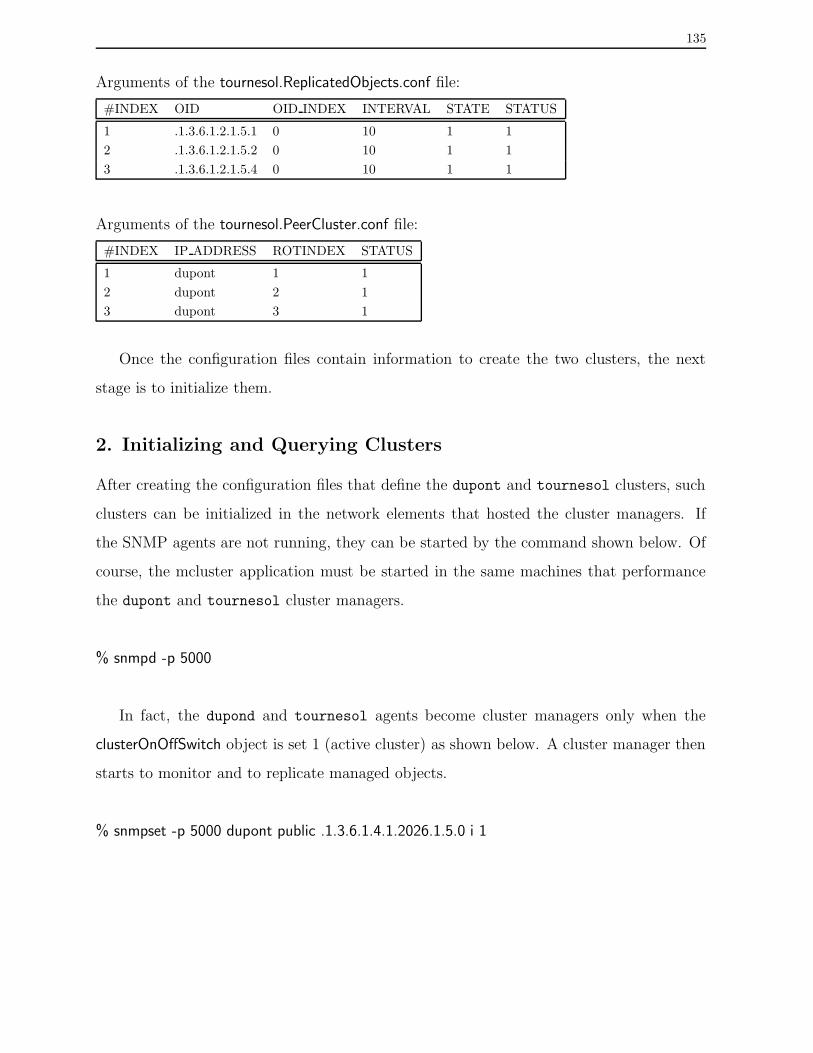
135
Arguments of the tournesol.ReplicatedObjects.conf file:
#INDEX OID OID INDEX INTERVAL STATE STATUS
1 .1.3.6.1.2.1.5.1 0 10 1 1
2 .1.3.6.1.2.1.5.2 0 10 1 1
3 .1.3.6.1.2.1.5.4 0 10 1 1
Arguments of the tournesol.PeerCluster.conf file:
#INDEX IP ADDRESS ROTINDEX STATUS
1 dupont 1 1
2 dupont 2 1
3 dupont 3 1
Once the configuration files contain information to create the two clusters, the next
stage is to initialize them.
2. Initializing and Querying Clusters
After creating the configuration files that define the dupont and tournesol clusters, such
clusters can be initialized in the network elements that hosted the cluster managers. If
the SNMP agents are not running, they can be started by the command shown below. Of
course, the mcluster application must be started in the same machines that performance
the dupont and tournesol cluster managers.
% snmpd -p 5000
In fact, the dupond and tournesol agents become cluster managers only when the
clusterOnOffSwitch object is set 1 (active cluster) as shown below. A cluster manager then
starts to monitor and to replicate managed objects.
% snmpset -p 5000 dupont public .1.3.6.1.4.1.2026.1.5.0 i 1

136
An SNMP agent can stop being a cluster manager in any time. For that, the clus-
terOnOffSwitch object must be set 6 (destroy cluster) as shown below. When the object is
set as destroy, such SNMP agent will not act as a cluster manager, but will keep running
as an ordinary SNMP agent.
% snmpset -p 5000 dupont public .1.3.6.1.4.1.2026.1.5.0 i 6
The tool translates the iso.org.dod.internet.private.enterprises.replicMIB OID as .1.3.6.1
.4.1.2026. The subtree replicObjects is under the Replic-MIB module, and is translated as
.1. The subtree replicObjects includes two subtrees called clusterDefinition and clusterRepli-
cation. We will use the .1.3.6.1.4.1.2026.1 value as part of the definition of a replication
OID in next commands.
Continuing the configuration of clusters above, we describe how to obtain information
over dupont and tournesol clusters. SNMP query commands like snmpwalk enable the
access to information of a given cluster. The command below obtains information of the
agent members of the dupont cluster.
% snmpwalk -p 5000 dupont public .1.3.6.1.4.1.2026.1.clusterDefinition.memberTable
memberTable.memberEntry.cmIndex.10 = Gauge32: 10
memberTable.memberEntry.cmIndex.20 = Gauge32: 20
memberTable.memberEntry.cmAddressType.10 = unknown(0)
memberTable.memberEntry.cmAddressType.20 = unknown(0)
memberTable.memberEntry.cmAddress.10 = IpAddress: 200.17.212.117
memberTable.memberEntry.cmAddress.20 = IpAddress: 200.17.212.102
memberTable.memberEntry.cmSecurity.10 = public
memberTable.memberEntry.cmSecurity.20 = public
memberTable.memberEntry.cmStatus.10 = active(1)
memberTable.memberEntry.cmStatus.20 = active(1)
The following command obtains information of the ICMP objects monitored by the
dupont cluster.
% snmpwalk -p 5000 dupont public .1.3.6.1.4.1.2026.1.clusterDefinition.repObjectTable
repObjectTable.repObjectEntry.roIndex.1 = Gauge32: 1
repObjectTable.repObjectEntry.roIndex.2 = Gauge32: 2
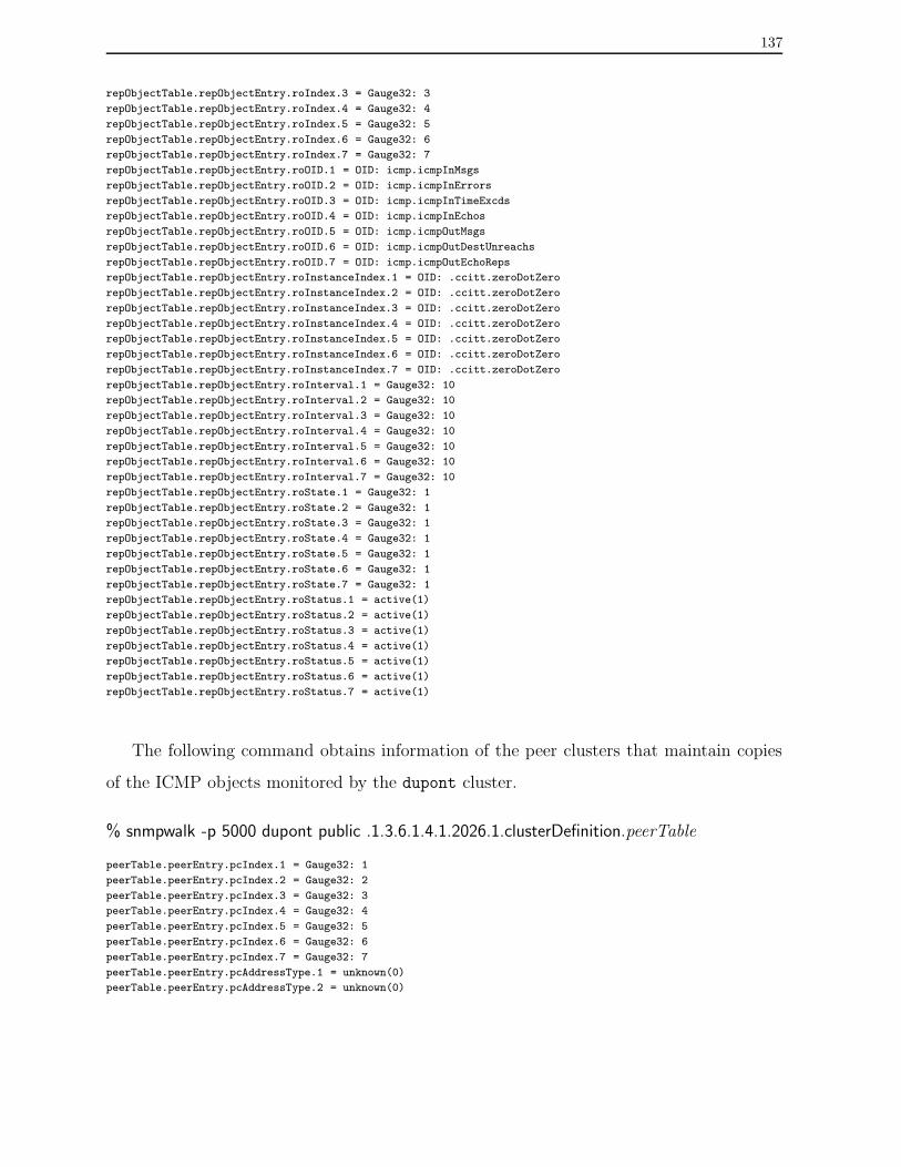
137
repObjectTable.repObjectEntry.roIndex.3 = Gauge32: 3
repObjectTable.repObjectEntry.roIndex.4 = Gauge32: 4
repObjectTable.repObjectEntry.roIndex.5 = Gauge32: 5
repObjectTable.repObjectEntry.roIndex.6 = Gauge32: 6
repObjectTable.repObjectEntry.roIndex.7 = Gauge32: 7
repObjectTable.repObjectEntry.roOID.1 = OID: icmp.icmpInMsgs
repObjectTable.repObjectEntry.roOID.2 = OID: icmp.icmpInErrors
repObjectTable.repObjectEntry.roOID.3 = OID: icmp.icmpInTimeExcds
repObjectTable.repObjectEntry.roOID.4 = OID: icmp.icmpInEchos
repObjectTable.repObjectEntry.roOID.5 = OID: icmp.icmpOutMsgs
repObjectTable.repObjectEntry.roOID.6 = OID: icmp.icmpOutDestUnreachs
repObjectTable.repObjectEntry.roOID.7 = OID: icmp.icmpOutEchoReps
repObjectTable.repObjectEntry.roInstanceIndex.1 = OID: .ccitt.zeroDotZero
repObjectTable.repObjectEntry.roInstanceIndex.2 = OID: .ccitt.zeroDotZero
repObjectTable.repObjectEntry.roInstanceIndex.3 = OID: .ccitt.zeroDotZero
repObjectTable.repObjectEntry.roInstanceIndex.4 = OID: .ccitt.zeroDotZero
repObjectTable.repObjectEntry.roInstanceIndex.5 = OID: .ccitt.zeroDotZero
repObjectTable.repObjectEntry.roInstanceIndex.6 = OID: .ccitt.zeroDotZero
repObjectTable.repObjectEntry.roInstanceIndex.7 = OID: .ccitt.zeroDotZero
repObjectTable.repObjectEntry.roInterval.1 = Gauge32: 10
repObjectTable.repObjectEntry.roInterval.2 = Gauge32: 10
repObjectTable.repObjectEntry.roInterval.3 = Gauge32: 10
repObjectTable.repObjectEntry.roInterval.4 = Gauge32: 10
repObjectTable.repObjectEntry.roInterval.5 = Gauge32: 10
repObjectTable.repObjectEntry.roInterval.6 = Gauge32: 10
repObjectTable.repObjectEntry.roInterval.7 = Gauge32: 10
repObjectTable.repObjectEntry.roState.1 = Gauge32: 1
repObjectTable.repObjectEntry.roState.2 = Gauge32: 1
repObjectTable.repObjectEntry.roState.3 = Gauge32: 1
repObjectTable.repObjectEntry.roState.4 = Gauge32: 1
repObjectTable.repObjectEntry.roState.5 = Gauge32: 1
repObjectTable.repObjectEntry.roState.6 = Gauge32: 1
repObjectTable.repObjectEntry.roState.7 = Gauge32: 1
repObjectTable.repObjectEntry.roStatus.1 = active(1)
repObjectTable.repObjectEntry.roStatus.2 = active(1)
repObjectTable.repObjectEntry.roStatus.3 = active(1)
repObjectTable.repObjectEntry.roStatus.4 = active(1)
repObjectTable.repObjectEntry.roStatus.5 = active(1)
repObjectTable.repObjectEntry.roStatus.6 = active(1)
repObjectTable.repObjectEntry.roStatus.7 = active(1)
The following command obtains information of the peer clusters that maintain copies
of the ICMP objects monitored by the dupont cluster.
% snmpwalk -p 5000 dupont public .1.3.6.1.4.1.2026.1.clusterDefinition.peerTable
peerTable.peerEntry.pcIndex.1 = Gauge32: 1
peerTable.peerEntry.pcIndex.2 = Gauge32: 2
peerTable.peerEntry.pcIndex.3 = Gauge32: 3
peerTable.peerEntry.pcIndex.4 = Gauge32: 4
peerTable.peerEntry.pcIndex.5 = Gauge32: 5
peerTable.peerEntry.pcIndex.6 = Gauge32: 6
peerTable.peerEntry.pcIndex.7 = Gauge32: 7
peerTable.peerEntry.pcAddressType.1 = unknown(0)
peerTable.peerEntry.pcAddressType.2 = unknown(0)
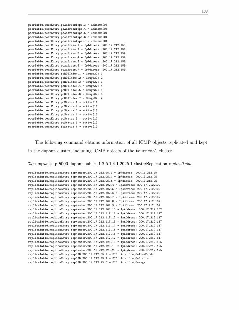
138
peerTable.peerEntry.pcAddressType.3 = unknown(0)
peerTable.peerEntry.pcAddressType.4 = unknown(0)
peerTable.peerEntry.pcAddressType.5 = unknown(0)
peerTable.peerEntry.pcAddressType.6 = unknown(0)
peerTable.peerEntry.pcAddressType.7 = unknown(0)
peerTable.peerEntry.pcAddress.1 = IpAddress: 200.17.212.159
peerTable.peerEntry.pcAddress.2 = IpAddress: 200.17.212.159
peerTable.peerEntry.pcAddress.3 = IpAddress: 200.17.212.159
peerTable.peerEntry.pcAddress.4 = IpAddress: 200.17.212.159
peerTable.peerEntry.pcAddress.5 = IpAddress: 200.17.212.159
peerTable.peerEntry.pcAddress.6 = IpAddress: 200.17.212.159
peerTable.peerEntry.pcAddress.7 = IpAddress: 200.17.212.159
peerTable.peerEntry.pcROTIndex.1 = Gauge32: 1
peerTable.peerEntry.pcROTIndex.2 = Gauge32: 2
peerTable.peerEntry.pcROTIndex.3 = Gauge32: 3
peerTable.peerEntry.pcROTIndex.4 = Gauge32: 4
peerTable.peerEntry.pcROTIndex.5 = Gauge32: 5
peerTable.peerEntry.pcROTIndex.6 = Gauge32: 6
peerTable.peerEntry.pcROTIndex.7 = Gauge32: 7
peerTable.peerEntry.pcStatus.1 = active(1)
peerTable.peerEntry.pcStatus.2 = active(1)
peerTable.peerEntry.pcStatus.3 = active(1)
peerTable.peerEntry.pcStatus.4 = active(1)
peerTable.peerEntry.pcStatus.5 = active(1)
peerTable.peerEntry.pcStatus.6 = active(1)
peerTable.peerEntry.pcStatus.7 = active(1)
The following command obtains information of all ICMP objects replicated and kept
in the dupont cluster, including ICMP objects of the tournesol cluster.
% snmpwalk -p 5000 dupont public .1.3.6.1.4.1.2026.1.clusterReplication.replicaTable
replicaTable.replicaEntry.repMember.200.17.212.95.1 = IpAddress: 200.17.212.95
replicaTable.replicaEntry.repMember.200.17.212.95.2 = IpAddress: 200.17.212.95
replicaTable.replicaEntry.repMember.200.17.212.95.3 = IpAddress: 200.17.212.95
replicaTable.replicaEntry.repMember.200.17.212.102.4 = IpAddress: 200.17.212.102
replicaTable.replicaEntry.repMember.200.17.212.102.5 = IpAddress: 200.17.212.102
replicaTable.replicaEntry.repMember.200.17.212.102.6 = IpAddress: 200.17.212.102
replicaTable.replicaEntry.repMember.200.17.212.102.7 = IpAddress: 200.17.212.102
replicaTable.replicaEntry.repMember.200.17.212.102.8 = IpAddress: 200.17.212.102
replicaTable.replicaEntry.repMember.200.17.212.102.9 = IpAddress: 200.17.212.102
replicaTable.replicaEntry.repMember.200.17.212.102.10 = IpAddress: 200.17.212.102
replicaTable.replicaEntry.repMember.200.17.212.117.11 = IpAddress: 200.17.212.117
replicaTable.replicaEntry.repMember.200.17.212.117.12 = IpAddress: 200.17.212.117
replicaTable.replicaEntry.repMember.200.17.212.117.13 = IpAddress: 200.17.212.117
replicaTable.replicaEntry.repMember.200.17.212.117.14 = IpAddress: 200.17.212.117
replicaTable.replicaEntry.repMember.200.17.212.117.15 = IpAddress: 200.17.212.117
replicaTable.replicaEntry.repMember.200.17.212.117.16 = IpAddress: 200.17.212.117
replicaTable.replicaEntry.repMember.200.17.212.117.17 = IpAddress: 200.17.212.117
replicaTable.replicaEntry.repMember.200.17.212.125.18 = IpAddress: 200.17.212.125
replicaTable.replicaEntry.repMember.200.17.212.125.19 = IpAddress: 200.17.212.125
replicaTable.replicaEntry.repMember.200.17.212.125.20 = IpAddress: 200.17.212.125
replicaTable.replicaEntry.repOID.200.17.212.95.1 = OID: icmp.icmpInTimeExcds
replicaTable.replicaEntry.repOID.200.17.212.95.2 = OID: icmp.icmpInErrors
replicaTable.replicaEntry.repOID.200.17.212.95.3 = OID: icmp.icmpInMsgs
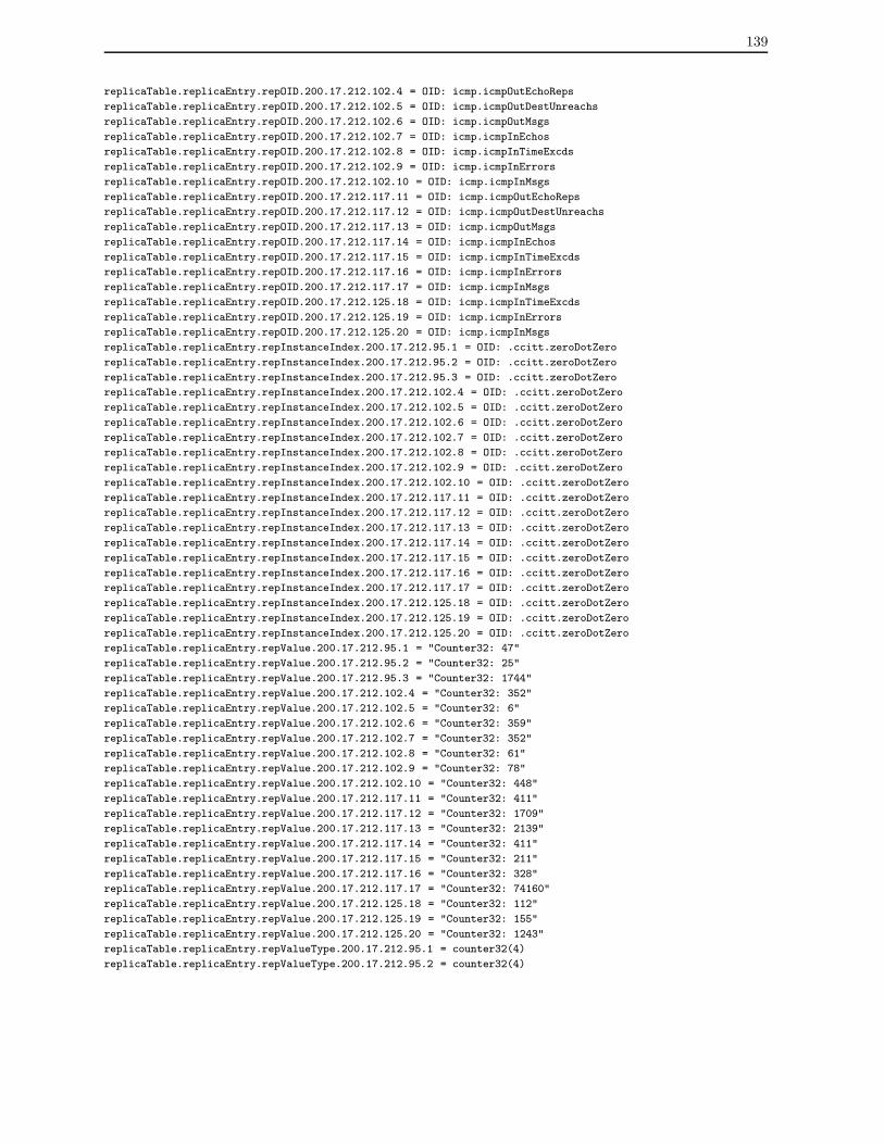
139
replicaTable.replicaEntry.repOID.200.17.212.102.4 = OID: icmp.icmpOutEchoReps
replicaTable.replicaEntry.repOID.200.17.212.102.5 = OID: icmp.icmpOutDestUnreachs
replicaTable.replicaEntry.repOID.200.17.212.102.6 = OID: icmp.icmpOutMsgs
replicaTable.replicaEntry.repOID.200.17.212.102.7 = OID: icmp.icmpInEchos
replicaTable.replicaEntry.repOID.200.17.212.102.8 = OID: icmp.icmpInTimeExcds
replicaTable.replicaEntry.repOID.200.17.212.102.9 = OID: icmp.icmpInErrors
replicaTable.replicaEntry.repOID.200.17.212.102.10 = OID: icmp.icmpInMsgs
replicaTable.replicaEntry.repOID.200.17.212.117.11 = OID: icmp.icmpOutEchoReps
replicaTable.replicaEntry.repOID.200.17.212.117.12 = OID: icmp.icmpOutDestUnreachs
replicaTable.replicaEntry.repOID.200.17.212.117.13 = OID: icmp.icmpOutMsgs
replicaTable.replicaEntry.repOID.200.17.212.117.14 = OID: icmp.icmpInEchos
replicaTable.replicaEntry.repOID.200.17.212.117.15 = OID: icmp.icmpInTimeExcds
replicaTable.replicaEntry.repOID.200.17.212.117.16 = OID: icmp.icmpInErrors
replicaTable.replicaEntry.repOID.200.17.212.117.17 = OID: icmp.icmpInMsgs
replicaTable.replicaEntry.repOID.200.17.212.125.18 = OID: icmp.icmpInTimeExcds
replicaTable.replicaEntry.repOID.200.17.212.125.19 = OID: icmp.icmpInErrors
replicaTable.replicaEntry.repOID.200.17.212.125.20 = OID: icmp.icmpInMsgs
replicaTable.replicaEntry.repInstanceIndex.200.17.212.95.1 = OID: .ccitt.zeroDotZero
replicaTable.replicaEntry.repInstanceIndex.200.17.212.95.2 = OID: .ccitt.zeroDotZero
replicaTable.replicaEntry.repInstanceIndex.200.17.212.95.3 = OID: .ccitt.zeroDotZero
replicaTable.replicaEntry.repInstanceIndex.200.17.212.102.4 = OID: .ccitt.zeroDotZero
replicaTable.replicaEntry.repInstanceIndex.200.17.212.102.5 = OID: .ccitt.zeroDotZero
replicaTable.replicaEntry.repInstanceIndex.200.17.212.102.6 = OID: .ccitt.zeroDotZero
replicaTable.replicaEntry.repInstanceIndex.200.17.212.102.7 = OID: .ccitt.zeroDotZero
replicaTable.replicaEntry.repInstanceIndex.200.17.212.102.8 = OID: .ccitt.zeroDotZero
replicaTable.replicaEntry.repInstanceIndex.200.17.212.102.9 = OID: .ccitt.zeroDotZero
replicaTable.replicaEntry.repInstanceIndex.200.17.212.102.10 = OID: .ccitt.zeroDotZero
replicaTable.replicaEntry.repInstanceIndex.200.17.212.117.11 = OID: .ccitt.zeroDotZero
replicaTable.replicaEntry.repInstanceIndex.200.17.212.117.12 = OID: .ccitt.zeroDotZero
replicaTable.replicaEntry.repInstanceIndex.200.17.212.117.13 = OID: .ccitt.zeroDotZero
replicaTable.replicaEntry.repInstanceIndex.200.17.212.117.14 = OID: .ccitt.zeroDotZero
replicaTable.replicaEntry.repInstanceIndex.200.17.212.117.15 = OID: .ccitt.zeroDotZero
replicaTable.replicaEntry.repInstanceIndex.200.17.212.117.16 = OID: .ccitt.zeroDotZero
replicaTable.replicaEntry.repInstanceIndex.200.17.212.117.17 = OID: .ccitt.zeroDotZero
replicaTable.replicaEntry.repInstanceIndex.200.17.212.125.18 = OID: .ccitt.zeroDotZero
replicaTable.replicaEntry.repInstanceIndex.200.17.212.125.19 = OID: .ccitt.zeroDotZero
replicaTable.replicaEntry.repInstanceIndex.200.17.212.125.20 = OID: .ccitt.zeroDotZero
replicaTable.replicaEntry.repValue.200.17.212.95.1 = "Counter32: 47"
replicaTable.replicaEntry.repValue.200.17.212.95.2 = "Counter32: 25"
replicaTable.replicaEntry.repValue.200.17.212.95.3 = "Counter32: 1744"
replicaTable.replicaEntry.repValue.200.17.212.102.4 = "Counter32: 352"
replicaTable.replicaEntry.repValue.200.17.212.102.5 = "Counter32: 6"
replicaTable.replicaEntry.repValue.200.17.212.102.6 = "Counter32: 359"
replicaTable.replicaEntry.repValue.200.17.212.102.7 = "Counter32: 352"
replicaTable.replicaEntry.repValue.200.17.212.102.8 = "Counter32: 61"
replicaTable.replicaEntry.repValue.200.17.212.102.9 = "Counter32: 78"
replicaTable.replicaEntry.repValue.200.17.212.102.10 = "Counter32: 448"
replicaTable.replicaEntry.repValue.200.17.212.117.11 = "Counter32: 411"
replicaTable.replicaEntry.repValue.200.17.212.117.12 = "Counter32: 1709"
replicaTable.replicaEntry.repValue.200.17.212.117.13 = "Counter32: 2139"
replicaTable.replicaEntry.repValue.200.17.212.117.14 = "Counter32: 411"
replicaTable.replicaEntry.repValue.200.17.212.117.15 = "Counter32: 211"
replicaTable.replicaEntry.repValue.200.17.212.117.16 = "Counter32: 328"
replicaTable.replicaEntry.repValue.200.17.212.117.17 = "Counter32: 74160"
replicaTable.replicaEntry.repValue.200.17.212.125.18 = "Counter32: 112"
replicaTable.replicaEntry.repValue.200.17.212.125.19 = "Counter32: 155"
replicaTable.replicaEntry.repValue.200.17.212.125.20 = "Counter32: 1243"
replicaTable.replicaEntry.repValueType.200.17.212.95.1 = counter32(4)
replicaTable.replicaEntry.repValueType.200.17.212.95.2 = counter32(4)

140
replicaTable.replicaEntry.repValueType.200.17.212.95.3 = counter32(4)
replicaTable.replicaEntry.repValueType.200.17.212.102.4 = counter32(4)
replicaTable.replicaEntry.repValueType.200.17.212.102.5 = counter32(4)
replicaTable.replicaEntry.repValueType.200.17.212.102.6 = counter32(4)
replicaTable.replicaEntry.repValueType.200.17.212.102.7 = counter32(4)
replicaTable.replicaEntry.repValueType.200.17.212.102.8 = counter32(4)
replicaTable.replicaEntry.repValueType.200.17.212.102.9 = counter32(4)
replicaTable.replicaEntry.repValueType.200.17.212.102.10 = counter32(4)
replicaTable.replicaEntry.repValueType.200.17.212.117.11 = counter32(4)
replicaTable.replicaEntry.repValueType.200.17.212.117.12 = counter32(4)
replicaTable.replicaEntry.repValueType.200.17.212.117.13 = counter32(4)
replicaTable.replicaEntry.repValueType.200.17.212.117.14 = counter32(4)
replicaTable.replicaEntry.repValueType.200.17.212.117.15 = counter32(4)
replicaTable.replicaEntry.repValueType.200.17.212.117.16 = counter32(4)
replicaTable.replicaEntry.repValueType.200.17.212.117.17 = counter32(4)
replicaTable.replicaEntry.repValueType.200.17.212.125.18 = counter32(4)
replicaTable.replicaEntry.repValueType.200.17.212.125.19 = counter32(4)
replicaTable.replicaEntry.repValueType.200.17.212.125.20 = counter32(4)
replicaTable.replicaEntry.repTimeStamp.200.17.212.95.1 = Timeticks: (290) 0:00:02.90
replicaTable.replicaEntry.repTimeStamp.200.17.212.95.2 = Timeticks: (291) 0:00:02.91
replicaTable.replicaEntry.repTimeStamp.200.17.212.95.3 = Timeticks: (301) 0:00:03.01
replicaTable.replicaEntry.repTimeStamp.200.17.212.102.4 = Timeticks: (19472) 0:03:14.72
replicaTable.replicaEntry.repTimeStamp.200.17.212.102.5 = Timeticks: (19472) 0:03:14.72
replicaTable.replicaEntry.repTimeStamp.200.17.212.102.6 = Timeticks: (19472) 0:03:14.72
replicaTable.replicaEntry.repTimeStamp.200.17.212.102.7 = Timeticks: (19472) 0:03:14.72
replicaTable.replicaEntry.repTimeStamp.200.17.212.102.8 = Timeticks: (19472) 0:03:14.72
replicaTable.replicaEntry.repTimeStamp.200.17.212.102.9 = Timeticks: (19472) 0:03:14.72
replicaTable.replicaEntry.repTimeStamp.200.17.212.102.10 = Timeticks: (19472) 0:03:14.72
replicaTable.replicaEntry.repTimeStamp.200.17.212.117.11 = Timeticks: (19472) 0:03:14.72
replicaTable.replicaEntry.repTimeStamp.200.17.212.117.12 = Timeticks: (19472) 0:03:14.72
replicaTable.replicaEntry.repTimeStamp.200.17.212.117.13 = Timeticks: (19472) 0:03:14.72
replicaTable.replicaEntry.repTimeStamp.200.17.212.117.14 = Timeticks: (19472) 0:03:14.72
replicaTable.replicaEntry.repTimeStamp.200.17.212.117.15 = Timeticks: (19473) 0:03:14.73
replicaTable.replicaEntry.repTimeStamp.200.17.212.117.16 = Timeticks: (19473) 0:03:14.73
replicaTable.replicaEntry.repTimeStamp.200.17.212.117.17 = Timeticks: (19474) 0:03:14.74
replicaTable.replicaEntry.repTimeStamp.200.17.212.125.18 = Timeticks: (290) 0:00:02.90
replicaTable.replicaEntry.repTimeStamp.200.17.212.125.19 = Timeticks: (291) 0:00:02.91
replicaTable.replicaEntry.repTimeStamp.200.17.212.125.20 = Timeticks: (292) 0:00:02.92
replicaTable.replicaEntry.repStatus.200.17.212.95.1 = active(1)
replicaTable.replicaEntry.repStatus.200.17.212.95.2 = active(1)
replicaTable.replicaEntry.repStatus.200.17.212.95.3 = active(1)
replicaTable.replicaEntry.repStatus.200.17.212.102.4 = active(1)
replicaTable.replicaEntry.repStatus.200.17.212.102.5 = active(1)
replicaTable.replicaEntry.repStatus.200.17.212.102.6 = active(1)
replicaTable.replicaEntry.repStatus.200.17.212.102.7 = active(1)
replicaTable.replicaEntry.repStatus.200.17.212.102.8 = active(1)
replicaTable.replicaEntry.repStatus.200.17.212.102.9 = active(1)
replicaTable.replicaEntry.repStatus.200.17.212.102.10 = active(1)
replicaTable.replicaEntry.repStatus.200.17.212.117.11 = active(1)
replicaTable.replicaEntry.repStatus.200.17.212.117.12 = active(1)
replicaTable.replicaEntry.repStatus.200.17.212.117.13 = active(1)
replicaTable.replicaEntry.repStatus.200.17.212.117.14 = active(1)
replicaTable.replicaEntry.repStatus.200.17.212.117.15 = active(1)
replicaTable.replicaEntry.repStatus.200.17.212.117.16 = active(1)
replicaTable.replicaEntry.repStatus.200.17.212.117.17 = active(1)
replicaTable.replicaEntry.repStatus.200.17.212.125.18 = active(1)
replicaTable.replicaEntry.repStatus.200.17.212.125.19 = active(1)
replicaTable.replicaEntry.repStatus.200.17.212.125.20 = active(1)

141
The same sequence of SNMP commands can be applied to the tournesol cluster, being
needed only to exchange the <destination host> parameter. The next command achieves
information of the agent members of the tournesol cluster.
% snmpwalk -p 5000 tournesol public .1.3.6.1.4.1.2026.1.clusterDefinition.memberTable
memberTable.memberEntry.cmIndex.10 = Gauge32: 10
memberTable.memberEntry.cmIndex.20 = Gauge32: 20
memberTable.memberEntry.cmAddressType.10 = unknown(0)
memberTable.memberEntry.cmAddressType.20 = unknown(0)
memberTable.memberEntry.cmAddress.10 = IpAddress: 200.17.212.95
memberTable.memberEntry.cmAddress.20 = IpAddress: 200.17.212.125
memberTable.memberEntry.cmSecurity.10 = public
memberTable.memberEntry.cmSecurity.20 = public
memberTable.memberEntry.cmStatus.10 = active(1)
memberTable.memberEntry.cmStatus.20 = active(1)
The next command obtains information of the ICMP objects monitored by the tournesol
cluster.
% snmpwalk -p 5000 tournesol public .1.3.6.1.4.1.2026.1.clusterDefinition.repObjectTable
repObjectTable.repObjectEntry.roIndex.1 = Gauge32: 1
repObjectTable.repObjectEntry.roIndex.2 = Gauge32: 2
repObjectTable.repObjectEntry.roIndex.3 = Gauge32: 3
repObjectTable.repObjectEntry.roOID.1 = OID: icmp.icmpInMsgs
repObjectTable.repObjectEntry.roOID.2 = OID: icmp.icmpInErrors
repObjectTable.repObjectEntry.roOID.3 = OID: icmp.icmpInTimeExcds
repObjectTable.repObjectEntry.roInstanceIndex.1 = OID: .ccitt.zeroDotZero
repObjectTable.repObjectEntry.roInstanceIndex.2 = OID: .ccitt.zeroDotZero
repObjectTable.repObjectEntry.roInstanceIndex.3 = OID: .ccitt.zeroDotZero
repObjectTable.repObjectEntry.roInterval.1 = Gauge32: 10
repObjectTable.repObjectEntry.roInterval.2 = Gauge32: 10
repObjectTable.repObjectEntry.roInterval.3 = Gauge32: 10
repObjectTable.repObjectEntry.roState.1 = Gauge32: 1
repObjectTable.repObjectEntry.roState.2 = Gauge32: 1
repObjectTable.repObjectEntry.roState.3 = Gauge32: 1
repObjectTable.repObjectEntry.roStatus.1 = active(1)
repObjectTable.repObjectEntry.roStatus.2 = active(1)
repObjectTable.repObjectEntry.roStatus.3 = active(1)
The next command obtains information of the peer clusters that maintain copies of the
ICMP objects monitored by the tournesol cluster.
% snmpwalk -p 5000 tournesol public .1.3.6.1.4.1.2026.1.clusterDefinition.peerTable

142
peerTable.peerEntry.pcIndex.1 = Gauge32: 1
peerTable.peerEntry.pcIndex.2 = Gauge32: 2
peerTable.peerEntry.pcIndex.3 = Gauge32: 3
peerTable.peerEntry.pcAddressType.1 = unknown(0)
peerTable.peerEntry.pcAddressType.2 = unknown(0)
peerTable.peerEntry.pcAddressType.3 = unknown(0)
peerTable.peerEntry.pcAddress.1 = IpAddress: 200.17.212.160
peerTable.peerEntry.pcAddress.2 = IpAddress: 200.17.212.160
peerTable.peerEntry.pcAddress.3 = IpAddress: 200.17.212.160
peerTable.peerEntry.pcROTIndex.1 = Gauge32: 1
peerTable.peerEntry.pcROTIndex.2 = Gauge32: 2
peerTable.peerEntry.pcROTIndex.3 = Gauge32: 3
peerTable.peerEntry.pcStatus.1 = active(1)
peerTable.peerEntry.pcStatus.2 = active(1)
peerTable.peerEntry.pcStatus.3 = active(1)
The next command obtains information of the ICMP objects replicated and kept in the
tournesol cluster, including ICMP objects of the dupont cluster.
% snmpwalk -p 5000 tournesol public .1.3.6.1.4.1.2026.1.clusterReplication.replicaTable
replicaTable.replicaEntry.repMember.200.17.212.95.1 = IpAddress: 200.17.212.95
replicaTable.replicaEntry.repMember.200.17.212.95.2 = IpAddress: 200.17.212.95
replicaTable.replicaEntry.repMember.200.17.212.95.3 = IpAddress: 200.17.212.95
replicaTable.replicaEntry.repMember.200.17.212.102.4 = IpAddress: 200.17.212.102
replicaTable.replicaEntry.repMember.200.17.212.102.5 = IpAddress: 200.17.212.102
replicaTable.replicaEntry.repMember.200.17.212.102.6 = IpAddress: 200.17.212.102
replicaTable.replicaEntry.repMember.200.17.212.102.7 = IpAddress: 200.17.212.102
replicaTable.replicaEntry.repMember.200.17.212.102.8 = IpAddress: 200.17.212.102
replicaTable.replicaEntry.repMember.200.17.212.102.9 = IpAddress: 200.17.212.102
replicaTable.replicaEntry.repMember.200.17.212.102.10 = IpAddress: 200.17.212.102
replicaTable.replicaEntry.repMember.200.17.212.117.11 = IpAddress: 200.17.212.117
replicaTable.replicaEntry.repMember.200.17.212.117.12 = IpAddress: 200.17.212.117
replicaTable.replicaEntry.repMember.200.17.212.117.13 = IpAddress: 200.17.212.117
replicaTable.replicaEntry.repMember.200.17.212.117.14 = IpAddress: 200.17.212.117
replicaTable.replicaEntry.repMember.200.17.212.117.15 = IpAddress: 200.17.212.117
replicaTable.replicaEntry.repMember.200.17.212.117.16 = IpAddress: 200.17.212.117
replicaTable.replicaEntry.repMember.200.17.212.117.17 = IpAddress: 200.17.212.117
replicaTable.replicaEntry.repMember.200.17.212.125.18 = IpAddress: 200.17.212.125
replicaTable.replicaEntry.repMember.200.17.212.125.19 = IpAddress: 200.17.212.125
replicaTable.replicaEntry.repMember.200.17.212.125.20 = IpAddress: 200.17.212.125
replicaTable.replicaEntry.repOID.200.17.212.95.1 = OID: icmp.icmpInTimeExcds
replicaTable.replicaEntry.repOID.200.17.212.95.2 = OID: icmp.icmpInErrors
replicaTable.replicaEntry.repOID.200.17.212.95.3 = OID: icmp.icmpInMsgs
replicaTable.replicaEntry.repOID.200.17.212.102.4 = OID: icmp.icmpOutEchoReps
replicaTable.replicaEntry.repOID.200.17.212.102.5 = OID: icmp.icmpOutDestUnreachs
replicaTable.replicaEntry.repOID.200.17.212.102.6 = OID: icmp.icmpOutMsgs
replicaTable.replicaEntry.repOID.200.17.212.102.7 = OID: icmp.icmpInEchos
replicaTable.replicaEntry.repOID.200.17.212.102.8 = OID: icmp.icmpInTimeExcds
replicaTable.replicaEntry.repOID.200.17.212.102.9 = OID: icmp.icmpInErrors
replicaTable.replicaEntry.repOID.200.17.212.102.10 = OID: icmp.icmpInMsgs
replicaTable.replicaEntry.repOID.200.17.212.117.11 = OID: icmp.icmpOutEchoReps
replicaTable.replicaEntry.repOID.200.17.212.117.12 = OID: icmp.icmpOutDestUnreachs
replicaTable.replicaEntry.repOID.200.17.212.117.13 = OID: icmp.icmpOutMsgs
replicaTable.replicaEntry.repOID.200.17.212.117.14 = OID: icmp.icmpInEchos

143
replicaTable.replicaEntry.repOID.200.17.212.117.15 = OID: icmp.icmpInTimeExcds
replicaTable.replicaEntry.repOID.200.17.212.117.16 = OID: icmp.icmpInErrors
replicaTable.replicaEntry.repOID.200.17.212.117.17 = OID: icmp.icmpInMsgs
replicaTable.replicaEntry.repOID.200.17.212.125.18 = OID: icmp.icmpInTimeExcds
replicaTable.replicaEntry.repOID.200.17.212.125.19 = OID: icmp.icmpInErrors
replicaTable.replicaEntry.repOID.200.17.212.125.20 = OID: icmp.icmpInMsgs
replicaTable.replicaEntry.repInstanceIndex.200.17.212.95.1 = OID: .ccitt.zeroDotZero
replicaTable.replicaEntry.repInstanceIndex.200.17.212.95.2 = OID: .ccitt.zeroDotZero
replicaTable.replicaEntry.repInstanceIndex.200.17.212.95.3 = OID: .ccitt.zeroDotZero
replicaTable.replicaEntry.repInstanceIndex.200.17.212.102.4 = OID: .ccitt.zeroDotZero
replicaTable.replicaEntry.repInstanceIndex.200.17.212.102.5 = OID: .ccitt.zeroDotZero
replicaTable.replicaEntry.repInstanceIndex.200.17.212.102.6 = OID: .ccitt.zeroDotZero
replicaTable.replicaEntry.repInstanceIndex.200.17.212.102.7 = OID: .ccitt.zeroDotZero
replicaTable.replicaEntry.repInstanceIndex.200.17.212.102.8 = OID: .ccitt.zeroDotZero
replicaTable.replicaEntry.repInstanceIndex.200.17.212.102.9 = OID: .ccitt.zeroDotZero
replicaTable.replicaEntry.repInstanceIndex.200.17.212.102.10 = OID: .ccitt.zeroDotZero
replicaTable.replicaEntry.repInstanceIndex.200.17.212.117.11 = OID: .ccitt.zeroDotZero
replicaTable.replicaEntry.repInstanceIndex.200.17.212.117.12 = OID: .ccitt.zeroDotZero
replicaTable.replicaEntry.repInstanceIndex.200.17.212.117.13 = OID: .ccitt.zeroDotZero
replicaTable.replicaEntry.repInstanceIndex.200.17.212.117.14 = OID: .ccitt.zeroDotZero
replicaTable.replicaEntry.repInstanceIndex.200.17.212.117.15 = OID: .ccitt.zeroDotZero
replicaTable.replicaEntry.repInstanceIndex.200.17.212.117.16 = OID: .ccitt.zeroDotZero
replicaTable.replicaEntry.repInstanceIndex.200.17.212.117.17 = OID: .ccitt.zeroDotZero
replicaTable.replicaEntry.repInstanceIndex.200.17.212.125.18 = OID: .ccitt.zeroDotZero
replicaTable.replicaEntry.repInstanceIndex.200.17.212.125.19 = OID: .ccitt.zeroDotZero
replicaTable.replicaEntry.repInstanceIndex.200.17.212.125.20 = OID: .ccitt.zeroDotZero
replicaTable.replicaEntry.repValue.200.17.212.95.1 = "Counter32: 47"
replicaTable.replicaEntry.repValue.200.17.212.95.2 = "Counter32: 25"
replicaTable.replicaEntry.repValue.200.17.212.95.3 = "Counter32: 1744"
replicaTable.replicaEntry.repValue.200.17.212.102.4 = "Counter32: 352"
replicaTable.replicaEntry.repValue.200.17.212.102.5 = "Counter32: 6"
replicaTable.replicaEntry.repValue.200.17.212.102.6 = "Counter32: 359"
replicaTable.replicaEntry.repValue.200.17.212.102.7 = "Counter32: 352"
replicaTable.replicaEntry.repValue.200.17.212.102.8 = "Counter32: 61"
replicaTable.replicaEntry.repValue.200.17.212.102.9 = "Counter32: 78"
replicaTable.replicaEntry.repValue.200.17.212.102.10 = "Counter32: 448"
replicaTable.replicaEntry.repValue.200.17.212.117.11 = "Counter32: 411"
replicaTable.replicaEntry.repValue.200.17.212.117.12 = "Counter32: 1709"
replicaTable.replicaEntry.repValue.200.17.212.117.13 = "Counter32: 2139"
replicaTable.replicaEntry.repValue.200.17.212.117.14 = "Counter32: 411"
replicaTable.replicaEntry.repValue.200.17.212.117.15 = "Counter32: 211"
replicaTable.replicaEntry.repValue.200.17.212.117.16 = "Counter32: 328"
replicaTable.replicaEntry.repValue.200.17.212.117.17 = "Counter32: 74160"
replicaTable.replicaEntry.repValue.200.17.212.125.18 = "Counter32: 112"
replicaTable.replicaEntry.repValue.200.17.212.125.19 = "Counter32: 155"
replicaTable.replicaEntry.repValue.200.17.212.125.20 = "Counter32: 1243"
replicaTable.replicaEntry.repValueType.200.17.212.95.1 = counter32(4)
replicaTable.replicaEntry.repValueType.200.17.212.95.2 = counter32(4)
replicaTable.replicaEntry.repValueType.200.17.212.95.3 = counter32(4)
replicaTable.replicaEntry.repValueType.200.17.212.102.4 = counter32(4)
replicaTable.replicaEntry.repValueType.200.17.212.102.5 = counter32(4)
replicaTable.replicaEntry.repValueType.200.17.212.102.6 = counter32(4)
replicaTable.replicaEntry.repValueType.200.17.212.102.7 = counter32(4)
replicaTable.replicaEntry.repValueType.200.17.212.102.8 = counter32(4)
replicaTable.replicaEntry.repValueType.200.17.212.102.9 = counter32(4)
replicaTable.replicaEntry.repValueType.200.17.212.102.10 = counter32(4)
replicaTable.replicaEntry.repValueType.200.17.212.117.11 = counter32(4)
replicaTable.replicaEntry.repValueType.200.17.212.117.12 = counter32(4)
replicaTable.replicaEntry.repValueType.200.17.212.117.13 = counter32(4)

144
replicaTable.replicaEntry.repValueType.200.17.212.117.14 = counter32(4)
replicaTable.replicaEntry.repValueType.200.17.212.117.15 = counter32(4)
replicaTable.replicaEntry.repValueType.200.17.212.117.16 = counter32(4)
replicaTable.replicaEntry.repValueType.200.17.212.117.17 = counter32(4)
replicaTable.replicaEntry.repValueType.200.17.212.125.18 = counter32(4)
replicaTable.replicaEntry.repValueType.200.17.212.125.19 = counter32(4)
replicaTable.replicaEntry.repValueType.200.17.212.125.20 = counter32(4)
replicaTable.replicaEntry.repTimeStamp.200.17.212.95.1 = Timeticks: (23) 0:00:00.23
replicaTable.replicaEntry.repTimeStamp.200.17.212.95.2 = Timeticks: (24) 0:00:00.24
replicaTable.replicaEntry.repTimeStamp.200.17.212.95.3 = Timeticks: (35) 0:00:00.35
replicaTable.replicaEntry.repTimeStamp.200.17.212.102.4 = Timeticks: (22239) 0:03:42.39
replicaTable.replicaEntry.repTimeStamp.200.17.212.102.5 = Timeticks: (22239) 0:03:42.39
replicaTable.replicaEntry.repTimeStamp.200.17.212.102.6 = Timeticks: (22239) 0:03:42.39
replicaTable.replicaEntry.repTimeStamp.200.17.212.102.7 = Timeticks: (22239) 0:03:42.39
replicaTable.replicaEntry.repTimeStamp.200.17.212.102.8 = Timeticks: (22239) 0:03:42.39
replicaTable.replicaEntry.repTimeStamp.200.17.212.102.9 = Timeticks: (22239) 0:03:42.39
replicaTable.replicaEntry.repTimeStamp.200.17.212.102.10 = Timeticks: (22239) 0:03:42.39
replicaTable.replicaEntry.repTimeStamp.200.17.212.117.11 = Timeticks: (22239) 0:03:42.39
replicaTable.replicaEntry.repTimeStamp.200.17.212.117.12 = Timeticks: (22239) 0:03:42.39
replicaTable.replicaEntry.repTimeStamp.200.17.212.117.13 = Timeticks: (22239) 0:03:42.39
replicaTable.replicaEntry.repTimeStamp.200.17.212.117.14 = Timeticks: (22239) 0:03:42.39
replicaTable.replicaEntry.repTimeStamp.200.17.212.117.15 = Timeticks: (22239) 0:03:42.39
replicaTable.replicaEntry.repTimeStamp.200.17.212.117.16 = Timeticks: (22239) 0:03:42.39
replicaTable.replicaEntry.repTimeStamp.200.17.212.117.17 = Timeticks: (22240) 0:03:42.40
replicaTable.replicaEntry.repTimeStamp.200.17.212.125.18 = Timeticks: (22) 0:00:00.22
replicaTable.replicaEntry.repTimeStamp.200.17.212.125.19 = Timeticks: (23) 0:00:00.23
replicaTable.replicaEntry.repTimeStamp.200.17.212.125.20 = Timeticks: (24) 0:00:00.24
replicaTable.replicaEntry.repStatus.200.17.212.95.1 = active(1)
replicaTable.replicaEntry.repStatus.200.17.212.95.2 = active(1)
replicaTable.replicaEntry.repStatus.200.17.212.95.3 = active(1)
replicaTable.replicaEntry.repStatus.200.17.212.102.4 = active(1)
replicaTable.replicaEntry.repStatus.200.17.212.102.5 = active(1)
replicaTable.replicaEntry.repStatus.200.17.212.102.6 = active(1)
replicaTable.replicaEntry.repStatus.200.17.212.102.7 = active(1)
replicaTable.replicaEntry.repStatus.200.17.212.102.8 = active(1)
replicaTable.replicaEntry.repStatus.200.17.212.102.9 = active(1)
replicaTable.replicaEntry.repStatus.200.17.212.102.10 = active(1)
replicaTable.replicaEntry.repStatus.200.17.212.117.11 = active(1)
replicaTable.replicaEntry.repStatus.200.17.212.117.12 = active(1)
replicaTable.replicaEntry.repStatus.200.17.212.117.13 = active(1)
replicaTable.replicaEntry.repStatus.200.17.212.117.14 = active(1)
replicaTable.replicaEntry.repStatus.200.17.212.117.15 = active(1)
replicaTable.replicaEntry.repStatus.200.17.212.117.16 = active(1)
replicaTable.replicaEntry.repStatus.200.17.212.117.17 = active(1)
replicaTable.replicaEntry.repStatus.200.17.212.125.18 = active(1)
replicaTable.replicaEntry.repStatus.200.17.212.125.19 = active(1)
replicaTable.replicaEntry.repStatus.200.17.212.125.20 = active(1)
This appendix described an example on how to configure clusters of agents using the
SNMP fault management tool. In general, the appendix presented the stages of definition,
initialization, and query to the clusters.

Appendix C
SNMP Objects Used in Performance
Analysis
IP - Internet Protocol
• ipInReceives: The total number of input datagrams received from interfaces, including
those received in error.
• ipInHdrErrors: The number of input datagrams discarded due to errors in their IP
headers, including bad checksums, version number mismatch, other format errors,
time-to-live exceeded, errors discovered in processing their IP options, etc.
• ipInAddrErrors: The number of input datagrams discarded because the IP address
in their IP header’s destination field was not a valid address to be received at this
entity. This count includes invalid addresses (e.g., 0.0.0.0) and addresses of unsup-
ported Classes (e.g., Class E). For entities which are not IP routers and therefore
do not forward datagrams, this counter includes datagrams discarded because the
destination address was not a local address.
• ipInDiscards: The number of input IP datagrams for which no problems were encoun-
tered to prevent their continued processing, but which were discarded (e.g., for lack
145

146
of buffer space). Note that this counter does not include any datagrams discarded
while awaiting re-assembly.
• ipInDelivers: The total number of input datagrams successfully delivered to IP user-
protocols (including ICMP).
• ipOutRequests: The total number of IP datagrams which local IP user- protocols
(including ICMP) supplied to IP in requests for transmission. Note that this counter
does not include any datagrams counted in ipForwDatagrams.
• ipOutDiscards: The number of output IP datagrams for which no problem was en-
countered to prevent their transmission to their destination, but which were discarded
(e.g., for lack of buffer space). Note that this counter would include datagrams
counted in ipForwDatagrams if any such packets met this (discretionary) discard
criterion.
• ipReasmTimeout: The maximum number of seconds which received fragments are
held while they are awaiting reassembly at this entity.
• ipReasmReqds: The number of IP fragments received which needed to be reassembled
at this entity.
• ipReasmOKs: The number of IP datagrams successfully re-assembled.
• ipReasmFails: The number of failures detected by the IP re-assembly algorithm (for
whatever reason: timed out, errors, etc). Note that this is not necessarily a count of
discarded IP fragments since some algorithms (notably the algorithm in RFC 815)
can lose track of the number of fragments by combining them as they are received.
• ipFrafOks: The number of IP datagrams that have been successfully fragmented at
this entity.
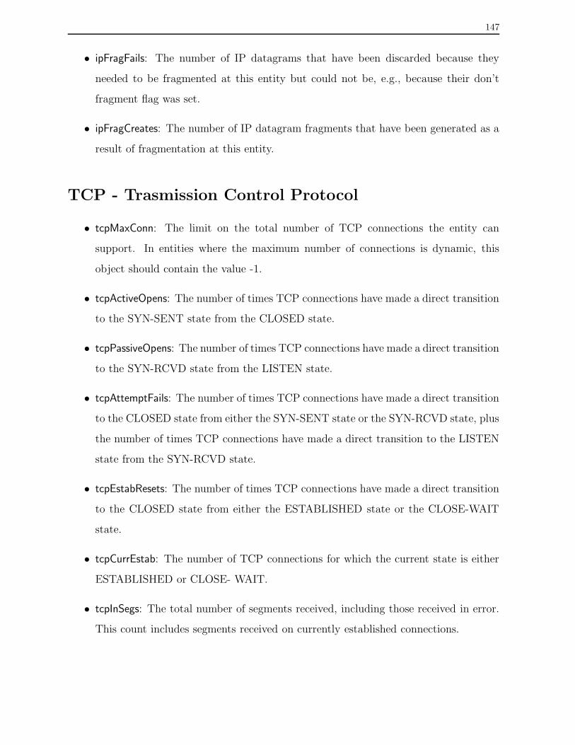
147
• ipFragFails: The number of IP datagrams that have been discarded because they
needed to be fragmented at this entity but could not be, e.g., because their don’t
fragment flag was set.
• ipFragCreates: The number of IP datagram fragments that have been generated as a
result of fragmentation at this entity.
TCP - Trasmission Control Protocol
• tcpMaxConn: The limit on the total number of TCP connections the entity can
support. In entities where the maximum number of connections is dynamic, this
object should contain the value -1.
• tcpActiveOpens: The number of times TCP connections have made a direct transition
to the SYN-SENT state from the CLOSED state.
• tcpPassiveOpens: The number of times TCP connections have made a direct transition
to the SYN-RCVD state from the LISTEN state.
• tcpAttemptFails: The number of times TCP connections have made a direct transition
to the CLOSED state from either the SYN-SENT state or the SYN-RCVD state, plus
the number of times TCP connections have made a direct transition to the LISTEN
state from the SYN-RCVD state.
• tcpEstabResets: The number of times TCP connections have made a direct transition
to the CLOSED state from either the ESTABLISHED state or the CLOSE-WAIT
state.
• tcpCurrEstab: The number of TCP connections for which the current state is either
ESTABLISHED or CLOSE- WAIT.
• tcpInSegs: The total number of segments received, including those received in error.
This count includes segments received on currently established connections.

148
• tcpOutSegs: The total number of segments sent, including those on current connec-
tions but excluding those containing only retransmitted octets.
• tcpRetransSegs: The total number of segments retransmitted - that is, the number of
TCP segments transmitted containing one or more previously transmitted octets.
• tcpInErrs: The total number of segments received in error (e.g., bad TCP checksums).
• tcpOutRsts: The number of TCP segments sent containing the RST flag.
UDP - User Datragram Protocol
• udpInDataGrams: The total number of UDP datagrams delivered to UDP users.
• udpNoPorts: The total number of received UDP datagrams for which there was no
application at the destination port.
• udpInErrors: The number of received UDP datagrams that could not be delivered for
reasons other than the lack of an application at the destination port.
• udpOutDatagrams: The total number of UDP datagrams sent from this entity.
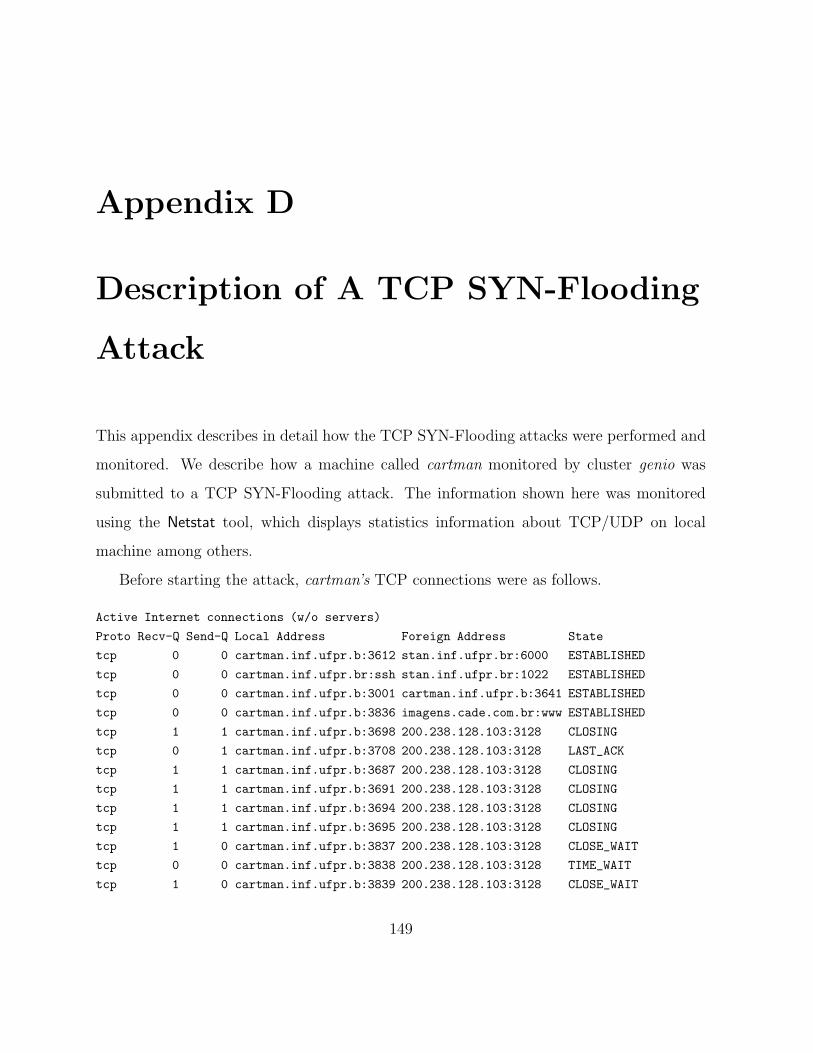
Appendix D
Description of A TCP SYN-Flooding
Attack
This appendix describes in detail how the TCP SYN-Flooding attacks were performed and
monitored. We describe how a machine called cartman monitored by cluster genio was
submitted to a TCP SYN-Flooding attack. The information shown here was monitored
using the Netstat tool, which displays statistics information about TCP/UDP on local
machine among others.
Before starting the attack, cartman’s TCP connections were as follows.
Active Internet connections (w/o servers)
Proto Recv-Q Send-Q Local Address Foreign Address State
tcp 0 0 cartman.inf.ufpr.b:3612 stan.inf.ufpr.br:6000 ESTABLISHED
tcp 0 0 cartman.inf.ufpr.br:ssh stan.inf.ufpr.br:1022 ESTABLISHED
tcp 0 0 cartman.inf.ufpr.b:3001 cartman.inf.ufpr.b:3641 ESTABLISHED
tcp 0 0 cartman.inf.ufpr.b:3836 imagens.cade.com.br:www ESTABLISHED
tcp 1 1 cartman.inf.ufpr.b:3698 200.238.128.103:3128 CLOSING
tcp 0 1 cartman.inf.ufpr.b:3708 200.238.128.103:3128 LAST_ACK
tcp 1 1 cartman.inf.ufpr.b:3687 200.238.128.103:3128 CLOSING
tcp 1 1 cartman.inf.ufpr.b:3691 200.238.128.103:3128 CLOSING
tcp 1 1 cartman.inf.ufpr.b:3694 200.238.128.103:3128 CLOSING
tcp 1 1 cartman.inf.ufpr.b:3695 200.238.128.103:3128 CLOSING
tcp 1 0 cartman.inf.ufpr.b:3837 200.238.128.103:3128 CLOSE_WAIT
tcp 0 0 cartman.inf.ufpr.b:3838 200.238.128.103:3128 TIME_WAIT
tcp 1 0 cartman.inf.ufpr.b:3839 200.238.128.103:3128 CLOSE_WAIT
149
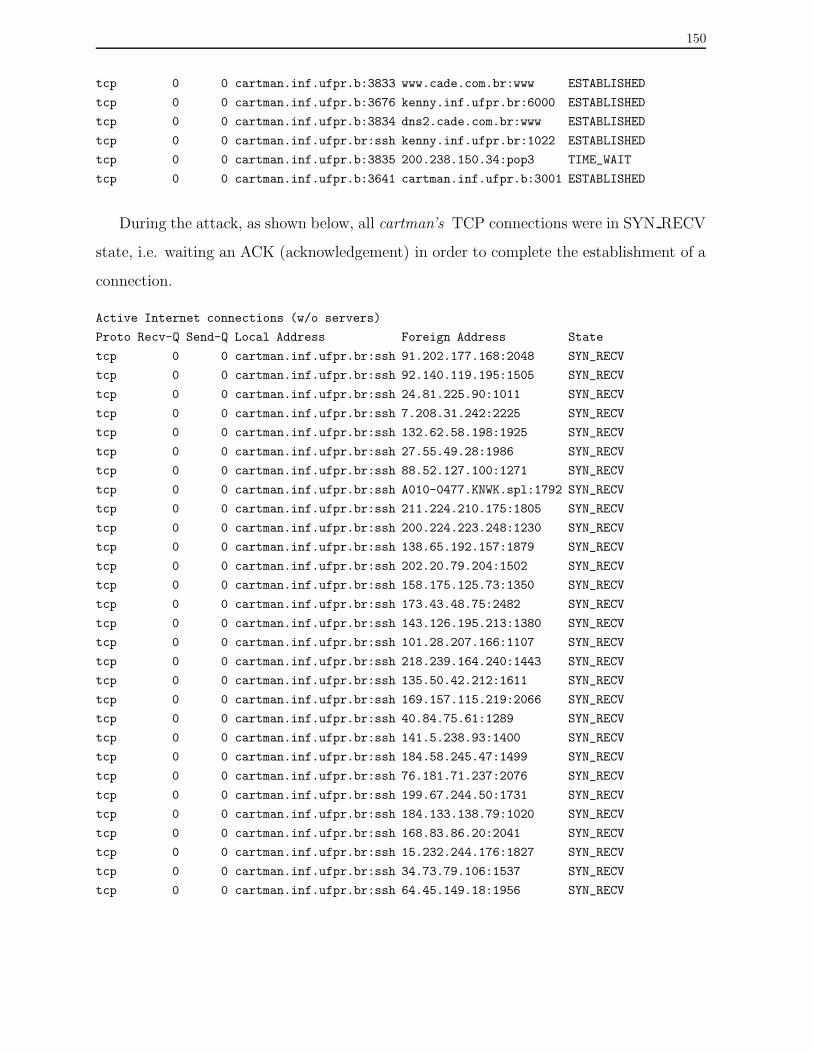
150
tcp 0 0 cartman.inf.ufpr.b:3833 www.cade.com.br:www ESTABLISHED
tcp 0 0 cartman.inf.ufpr.b:3676 kenny.inf.ufpr.br:6000 ESTABLISHED
tcp 0 0 cartman.inf.ufpr.b:3834 dns2.cade.com.br:www ESTABLISHED
tcp 0 0 cartman.inf.ufpr.br:ssh kenny.inf.ufpr.br:1022 ESTABLISHED
tcp 0 0 cartman.inf.ufpr.b:3835 200.238.150.34:pop3 TIME_WAIT
tcp 0 0 cartman.inf.ufpr.b:3641 cartman.inf.ufpr.b:3001 ESTABLISHED
During the attack, as shown below, all cartman’s TCP connections were in SYN RECV
state, i.e. waiting an ACK (acknowledgement) in order to complete the establishment of a
connection.
Active Internet connections (w/o servers)
Proto Recv-Q Send-Q Local Address Foreign Address State
tcp 0 0 cartman.inf.ufpr.br:ssh 91.202.177.168:2048 SYN_RECV
tcp 0 0 cartman.inf.ufpr.br:ssh 92.140.119.195:1505 SYN_RECV
tcp 0 0 cartman.inf.ufpr.br:ssh 24.81.225.90:1011 SYN_RECV
tcp 0 0 cartman.inf.ufpr.br:ssh 7.208.31.242:2225 SYN_RECV
tcp 0 0 cartman.inf.ufpr.br:ssh 132.62.58.198:1925 SYN_RECV
tcp 0 0 cartman.inf.ufpr.br:ssh 27.55.49.28:1986 SYN_RECV
tcp 0 0 cartman.inf.ufpr.br:ssh 88.52.127.100:1271 SYN_RECV
tcp 0 0 cartman.inf.ufpr.br:ssh A010-0477.KNWK.spl:1792 SYN_RECV
tcp 0 0 cartman.inf.ufpr.br:ssh 211.224.210.175:1805 SYN_RECV
tcp 0 0 cartman.inf.ufpr.br:ssh 200.224.223.248:1230 SYN_RECV
tcp 0 0 cartman.inf.ufpr.br:ssh 138.65.192.157:1879 SYN_RECV
tcp 0 0 cartman.inf.ufpr.br:ssh 202.20.79.204:1502 SYN_RECV
tcp 0 0 cartman.inf.ufpr.br:ssh 158.175.125.73:1350 SYN_RECV
tcp 0 0 cartman.inf.ufpr.br:ssh 173.43.48.75:2482 SYN_RECV
tcp 0 0 cartman.inf.ufpr.br:ssh 143.126.195.213:1380 SYN_RECV
tcp 0 0 cartman.inf.ufpr.br:ssh 101.28.207.166:1107 SYN_RECV
tcp 0 0 cartman.inf.ufpr.br:ssh 218.239.164.240:1443 SYN_RECV
tcp 0 0 cartman.inf.ufpr.br:ssh 135.50.42.212:1611 SYN_RECV
tcp 0 0 cartman.inf.ufpr.br:ssh 169.157.115.219:2066 SYN_RECV
tcp 0 0 cartman.inf.ufpr.br:ssh 40.84.75.61:1289 SYN_RECV
tcp 0 0 cartman.inf.ufpr.br:ssh 141.5.238.93:1400 SYN_RECV
tcp 0 0 cartman.inf.ufpr.br:ssh 184.58.245.47:1499 SYN_RECV
tcp 0 0 cartman.inf.ufpr.br:ssh 76.181.71.237:2076 SYN_RECV
tcp 0 0 cartman.inf.ufpr.br:ssh 199.67.244.50:1731 SYN_RECV
tcp 0 0 cartman.inf.ufpr.br:ssh 184.133.138.79:1020 SYN_RECV
tcp 0 0 cartman.inf.ufpr.br:ssh 168.83.86.20:2041 SYN_RECV
tcp 0 0 cartman.inf.ufpr.br:ssh 15.232.244.176:1827 SYN_RECV
tcp 0 0 cartman.inf.ufpr.br:ssh 34.73.79.106:1537 SYN_RECV
tcp 0 0 cartman.inf.ufpr.br:ssh 64.45.149.18:1956 SYN_RECV

151
tcp 0 0 cartman.inf.ufpr.br:ssh 113.160.92.158:1949 SYN_RECV
tcp 0 0 cartman.inf.ufpr.br:ssh 141.129.75.98:1641 SYN_RECV
tcp 0 0 cartman.inf.ufpr.br:ssh 211.12.182.207:1385 SYN_RECV
tcp 0 0 cartman.inf.ufpr.br:ssh 195.246.50.198:2370 SYN_RECV
tcp 0 0 cartman.inf.ufpr.br:ssh 137.39.221.120:1606 SYN_RECV
tcp 0 0 cartman.inf.ufpr.br:ssh 12.207.109.150:1972 SYN_RECV
tcp 0 0 cartman.inf.ufpr.br:ssh 142.107.30.156:1642 SYN_RECV
tcp 0 0 cartman.inf.ufpr.br:ssh 62.97.246.129:1382 SYN_RECV
tcp 0 0 cartman.inf.ufpr.br:ssh 160.219.89.160:1551 SYN_RECV
tcp 0 0 cartman.inf.ufpr.br:ssh 144.115.66.216:2298 SYN_RECV
tcp 0 0 cartman.inf.ufpr.br:ssh 21.118.37.173:2350 SYN_RECV
After stopping the attack, each TCP connection with SYN RECV remained in the
connection queue until a timer expired, typically for about one minute. Next, as shown
below, the connection queue decreased and TCP services were available again.
Active Internet connections (w/o servers)
Proto Recv-Q Send-Q Local Address Foreign Address State
tcp 0 0 cartman.inf.ufpr.b:3612 stan.inf.ufpr.br:6000 ESTABLISHED
tcp 0 0 cartman.inf.ufpr.br:ssh stan.inf.ufpr.br:1022 ESTABLISHED
tcp 1 0 cartman.inf.ufpr.b:3878 200.238.128.103:3128 CLOSE_WAIT
tcp 0 0 cartman.inf.ufpr.b:3001 cartman.inf.ufpr.b:3641 ESTABLISHED
tcp 0 1 cartman.inf.ufpr.b:3889 k4.linksynergy.com:www SYN_SENT
tcp 0 0 cartman.inf.ufpr.b:3676 kenny.inf.ufpr.br:6000 ESTABLISHED
tcp 0 0 cartman.inf.ufpr.br:ssh kenny.inf.ufpr.br:1022 ESTABLISHED
tcp 0 0 cartman.inf.ufpr.b:3884 merlin.eb.com:www TIME_WAIT
tcp 0 0 cartman.inf.ufpr.b:3881 merlin.eb.com:www TIME_WAIT
tcp 0 0 cartman.inf.ufpr.b:3882 merlin.eb.com:www ESTABLISHED
tcp 0 0 cartman.inf.ufpr.b:3888 200.238.150.34:pop3 TIME_WAIT
tcp 0 0 cartman.inf.ufpr.b:3885 200.238.150.34:pop3 FIN_WAIT2
tcp 0 0 cartman.inf.ufpr.b:3641 cartman.inf.ufpr.b:3001 ESTABLISHED