dr. josé carlos mendes abb brasil
TRANSCRIPT

© ABB Brasil – PP DivisionPower Transformers2015Apr23, JCM - | Page 1
ABB BrasilPower Products Division
Dr. José Carlos MendesGte Tecnologia Transmissão e Produtos de PotênciaGte Desenvolvimento & EngenhariaEngenheiro Corporativo Executivo Global
ABB Asea Brown BoveriDivisão de Produtos de PotênciaTransformadores de PotênciaSão Paulo, SP - Brasil
email: [email protected]: + 55 11 2464 8410cel: + 55 11 9 8354 5358
+ 55 11 9 8112 7575
LIMA PEJornadas Técnicas 2015
2015Abr23
Power Transformers:Life Cycle and Operational Cost Optimization –
Conventional, Wind and Solar Applications

© ABB Brasil – PP DivisionPower Transformers2015Apr23, JCM - | Page 2
Guarulhos, São Paulo - BR
ABB BrazilPower Products Division
Power Transformers
Blumenau, SC - BR
n PPTR Power Transformersl power transformers up to 765kVl shunt reactors up to 765kVl heavy current industrial transformersl service (Eng Solution, Factory and Site Repairs,
Monitoring Systems, TrServices)l insulation componentsl transformer components (Bushings, Tap
Changers, etc)n PPMV Medium Voltage, PPHV High Voltage
PPTR Distribution Transformers
ABB Brasil Power Products DivisionPower and Distribution Transformers
© ABB Brasil – PP DivisionPower Transformers2015Apr23, JCM - | Page 3
ContentContent
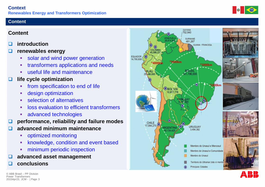
Content
q introductionq renewables energy
§ solar and wind power generation§ transformers applications and needs§ useful life and maintenance
q life cycle optimization§ from specification to end of life§ design optimization§ selection of alternatives§ loss evaluation to efficient transformers§ advanced technologies
q performance, reliability and failure modesq advanced minimum maintenance
§ optimized monitoring§ knowledge, condition and event based§ minimum periodic inspection
q advanced asset managementq conclusions
ContextRenewables Energy and Transformers Optimization
© ABB Brasil – PP DivisionPower Transformers2015Apr23, JCM - | Page 4
Renewables Energy and Transformers ApplicationsSolar and Wind Power Generation – Trends and Transformers Needs

© ABB Brasil – PP DivisionPower Transformers2015Apr23, JCM - | Page 5
Solar and Wind Power PlantsPower Transformers Applications
PE MINEMPlan Energético Nacional 2014-2025
PERU and PBI evolution
Maximum Demand2013-2025

© ABB Brasil – PP DivisionPower Transformers2015Apr23, JCM - | Page 6
Solar and Wind Power PlantsPower Transformers Applications
PE MINEMPlan Energético Nacional 2014-2025
PERU and PBI evolution
Ingress of RenewablesEnergy 2014-2017
Investments 2015-2025 Mio USD

© ABB Brasil – PP DivisionPower Transformers2015Apr23, JCM - | Page 7
Solar and Wind Power PlantsPower Transformers Applications
PE MINEMPlan Energético Nacional 2014-2025
Wind Power- total 77 000 MW- usable 22 500MW
Ingress of RenewablesEnergy 2014-2017
Solar Power- total 77 000 MW- usable 22 500MW

© ABB Brasil – PP DivisionPower Transformers2015Apr23, JCM - | Page 8
Solar and Wind Power PlantsPower Transformers Applications
CollectorTransformer
InverterTransformer
InverterTransformer
ConnectionTransformer
CollectorTransformer
InverterTransformer
InverterTransformer
PV DCGenerator
PV DCGenerator
PV DCGenerator
PV DCGenerator
Connection, GSUTransformer
ConnectionTransformer
WTGTransformer
CollectorTransformer
CollectorTransformer
WTGTransformer
WTGTransformer
WTGTransformer
Wind Farms
Solar CSP
Solar PV
WTG Technologies

© ABB Brasil – PP DivisionPower Transformers2015Apr23, JCM - | Page 9
Power TransformersSolar and Wind Power Applications
Wind Farm – Daily Variation of Load Current, Voltage, Power Factor
Wind Farm Collector Substation - Load Current, Voltage and Power Factor
Current, Arms Voltage, pu power factor, pu

© ABB Brasil – PP DivisionPower Transformers2015Apr23, JCM - | Page 10
Wind Farm – Steady State Voltage Load Flow
Us LF IL UHVc ULVc Ulim
pu % pu pu pu pu
1.00 54 0.28 1.035 1.044 1.091
1.05 54 0,28 1.086 1.095 1.091
1.00 100 0.52 1.038 1.052 1.070
1.05 100 0.52 1.089 1.100 1.070
TL69-1
Connection SSBUS 230 kV
G
Collector SSBUS 69 kV
WTGBUS 690 V
Wind Farm 2
Wind Farm 3
Wind Farm 4
Wind Farm 5
US
TL69-2
CapacitorBank
TL230 - 1
TL230 - 2
TL230 - 3
TL230 - 4
TL230 - 5
TL230 - 6
CapacitorBank
Connection SSBUS 69 kV
Collector SSBUS 34.5 kV
UChv
UClv
IL , LF = load factor
Wind Farm 1
Ulim
ConnectionTransformer
CollectorTransformer
WTGTransformer
WTGBUS 690 V
Power TransformersSolar and Wind Power Applications
© ABB Brasil – PP DivisionPower Transformers2015Apr23, JCM - | Page 11
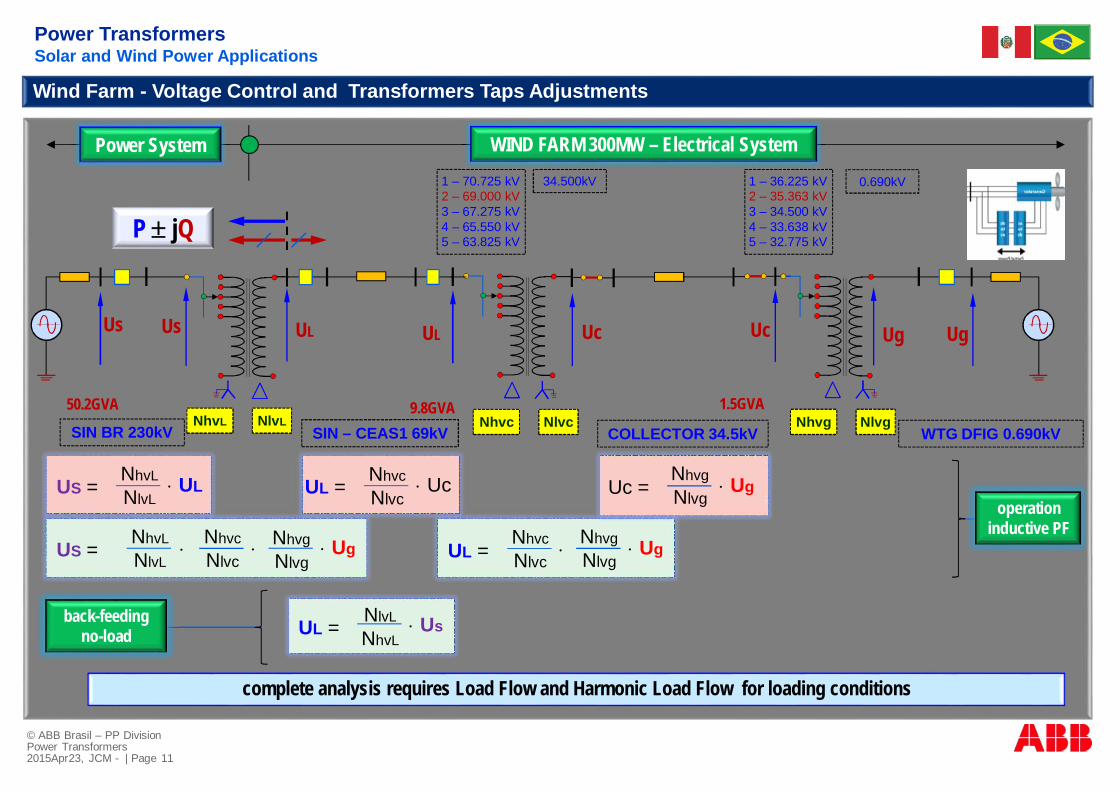
Wind Farm - Voltage Control and Transformers Taps Adjustments
back-feedingno-load
SIN BR 230kV SIN – CEAS1 69kV COLLECTOR 34.5kV WTG DFIG 0.690kV
1 – 70.725 kV2 – 69.000 kV3 – 67.275 kV4 – 65.550 kV5 – 63.825 kV
1 – 36.225 kV2 – 35.363 kV3 – 34.500 kV4 – 33.638 kV5 – 32.775 kV
0.690kV34.500kV
Nhvc Nlvc Nhvg Nlvg
UgUgUcUcULUs Us UL
Uc =NhvgNlvg
× UgUL = NhvcNlvc
× Uc
UL =NhvcNlvc
×NhvgNlvg
× Ug
UL = NlvL
NhvL× Us
NhvL NlvL
operationinductive PF
US = NhvcNlvc
× NhvgNlvg
× UgNhvL
NlvL×
US = × ULNhvL
NlvL
P ± jQ
Power System WIND FARM 300MW – Electrical System
complete analysis requires Load Flow and Harmonic Load Flow for loading conditions
50.2GVA 1.5GVA9.8GVA
Power TransformersSolar and Wind Power Applications

© ABB Brasil – PP DivisionPower Transformers2015Apr23, JCM - | Page 12
Renewables Energy and Transformers ApplicationsLife Cycle – From Specification to End of Life

© ABB Brasil – PP DivisionPower Transformers2015Apr23, JCM - | Page 13
Power TransformersLife Cycle Optimization
Transformer Life Cycle

© ABB Brasil – PP DivisionPower Transformers2015Apr23, JCM - | Page 14
Specification, Design, Manufacturing, Tests, Transportation, Receiving,Storage, Installation, Operation, Monitoring, Maintenance, End of Life
Transformer Life Cycle
Power TransformersLife Cycle Optimization

© ABB Brasil – PP DivisionPower Transformers2015Apr23, JCM - | Page 15
Renewables Energy and Transformers ApplicationsLife Cycle – Design Optimization

© ABB Brasil – PP DivisionPower Transformers2015Apr23, JCM - | Page 16
Transformer§ core§ windings§ connections§ tank§ expansion tank§ accessoriesØ bushingsØ tap-changersØ radiatorsØ motor-fansØ thermometers, level indicators, Buchholz
relay, pressure relief valve, pressure relay,air breathers, etc
Ø bushing current transformers BCTsØ surge arrestersØ command, control and protectionsØ sensors and monitoring system
Power Transformer
Power TransformersLife Cycle Optimization and Global Evaluation of Alternatives

© ABB Brasil – PP DivisionPower Transformers2015Apr23, JCM - | Page 17
§ core induction§ no load losses - core§ load losses – windings, connections, metal
structures§ short-circuit impedances§ leakage flux§ inrush-current§ short-circuit current§ short-circuit forces§ core over-excitation§ DC excitation component§ voltage and current harmonics§ overloading§ insulation (windings and main)§ cooling and temperature rise§ noise level§ new technologies (Nomex, Vegetable Oil,
Vacuum OLTC, CTCs, Bushings RIP & RIS, etc)§ on-line monitoring and diagnostic§ on-line asset management
Power Transformer – Design Optimization
Transformer Design
§ cost optimization§ no load losses optimization§ load losses optimization§ characteristics optimization§ performance (thermal, loading, short-
circuit, etc) optimization§ transportation limits§ interchanged ability
§ transformer optimization strategies:Ø Total Initial CostØ Losses CostØ Total Operational CostØ Life Cycle Total Cost
Transformer Design Optimization
Power TransformersLife Cycle Optimization and Global Evaluation of Alternatives

© ABB Brasil – PP DivisionPower Transformers2015Apr23, JCM - | Page 18
Steps:
1. Technical Specification2. Procumeremt process3. Manufacturer and Factory qualification4. Quotations, Technical&Economic Analysis, Purchase, Contracts5. Electrical Design6. Design Review7. Mechanical Design8. Manufacturing9. Factory Final Acceptance Tests10. Final Tests Results and Analysis11. FRA at Factory before transport12. Monitored Transportation13. FRA at Site after transportation14. Erection at Site15. Commissioning at Site16. Energization17. Operation18. Monitoring19. Maintenance
Transformer Life Cycle
Power TransformersLife Cycle Optimization and Global Evaluation of Alternatives

© ABB Brasil – PP DivisionPower Transformers2015Apr23, JCM - | Page 19
Renewables Energy and Transformers ApplicationsLife Cycle – Optimized Selection of Alternatives

© ABB Brasil – PP DivisionPower Transformers2015Apr23, JCM - | Page 20
USD$kVA x Useful Life x Overloading Factor
Capital Cost:n purchasen transportn installation
Operation Cost:n losses (noLoad,
Load, Auxiliar)n maintenancen insurance premiumn repairsn performance
End of Life Cost:n replacementn transfern refurbishment
NPV, Total Cost / Life Cycle $ = $1+$2+$3
$1
$2
$3
Warranty of Useful Life Garantida, year
Life Cycle, years
Transformer Life Cycle
Power TransformersLife Cycle Optimization and Global Evaluation of Alternatives

© ABB Brasil – PP DivisionPower Transformers2015Apr23, JCM - | Page 21
Usual Method does not Evaluate:§ Quality§ Design and Manufacturing§ Withstand (electrical mechanical, thermal)
§ Risk of Failure§ Useful Life Expectancy§ Overloading Capability
Usual Evaluation Method:
n initial total cost:q equipment initial costq spare components costq transport costq installation cost (erection, supervision, etc)q comissioning costq extended guarantee cost
n losses cost (capitalisation)q no-load, load, auxiliar losses
n technical data tableq technical performance dataq technical guaranteed data
Global Value Index:§ total initial price, USD$§ rated power, kVA§ guaranteed useful life, years§ guaranteed overload, pu§ return on investment, % year
Transformer Life Cycle
Power TransformersLife Cycle Optimization and Global Evaluation of Alternatives

© ABB Brasil – PP DivisionPower Transformers2015Apr23, JCM - | Page 22
Technical Performance Evaluation
§ quantitative evaluation method§ powerful technical performance comparison of
different suppliers§ technical & economical equalization of several
technical quotations§ main performance data:Ø thermal performance (core, windings, connections)Ø useful life (as per IEEE)Ø total lossesØ short-circuit (IEC)Ø certified/qualified seismic performanceØ transient voltages and internal insulation withstand
(switching of reactors!)Ø reliability analysisØ global economic evaluation
Guaranteed Technical Data
To meet declared guaranteedtechnical data it is not a guarantee:
q for a specified minimum performanceq for a specified useful lifeq for a short-circuit withstand with
reliabilityq for a economic optimized solutionq for a minimum LC total costq for a reliable operation life with no
failure
USD$kVA x UsefulLife x OverLoadingFactor
Increasing Asset Quality: Minimum Maintenance
Power Equipment Performance Equalization
Power TransformersLife Cycle Optimization and Global Evaluation of Alternatives

© ABB Brasil – PP DivisionPower Transformers2015Apr23, JCM - | Page 23
USD$kVA x UsefulLife x OverLoadingFactor
Power Equipment Performance Equalization
Alternatives A B
Characteristic Unit Cellulose ThUpgradedPaper, 65Cdeg
Hybrid, Nomex Paper,95Cdeg
Initial Cost USD 1 000 000 1 200 000Rated Power kVA 50 000 60 000Useful Life years 42 80Overloading Factor pu 1.15 1.40Overloadind Time h 4 4Global Value Index USD/kVA . year 0.46 0.23Ratio % 100 50.4
Power TransformersLife Cycle Optimization and Global Evaluation of Alternatives

© ABB Brasil – PP DivisionPower Transformers2015Apr23, JCM - | Page 24
Renewables Energy and Transformers ApplicationsLife Cycle – Losses Evaluations to Efficient Transformers

© ABB Brasil – PP DivisionPower Transformers2015Apr23, JCM - | Page 25
q core induction, diameter, massq winding current densityq distance between windingsq winding diameters, width, height, massq tank mass
lossescost
manufac-turing cost
transformer mass, kg
valu
e,$
manufac-turing cost
transformer mass, kg
valu
e,$
manufacturingcost + losses cost
$$ Total Cost = Manufacturing Cost + Losses Cost = f (design variables)
Loss Capitalisation Cost, $/kWmaximum cost to pay to reducetransformer losse by 1 kW
Power Equipment Performance Equalization
lossescost
optimization
Manufacturing Cost:§ material§ labor§ over-heads
Power TransformersLife Cycle Optimization and Performance Equalization

© ABB Brasil – PP DivisionPower Transformers2015Apr23, JCM - | Page 26
No LoadLosses
EvaluationsValues
Interest rate 0.02 $/kWh 0.03 $/kWh 0.04 $/kWh
4% 3100 4650 6200
8% 2100 3150 4200
12% 1550 2300 3100
1 kW losses in 30 years 8600 hours/year
Load Loss evaluations depend on load profile per day, months etc and aretherefore a varying % of the full year value
Power Equipment Performance Equalization
Power TransformersLife Cycle Optimization and Performance Equalization
© ABB Brasil – PP DivisionPower Transformers2015Apr23, JCM - | Page 27
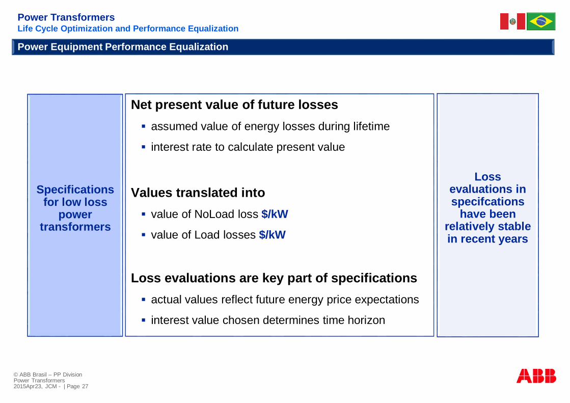
Specificationsfor low loss
powertransformers
Net present value of future losses§ assumed value of energy losses during lifetime
§ interest rate to calculate present value
Values translated into§ value of NoLoad loss $/kW
§ value of Load losses $/kW
Loss evaluations are key part of specifications§ actual values reflect future energy price expectations
§ interest value chosen determines time horizon
Power Equipment Performance Equalization
Lossevaluations inspecifcations
have beenrelatively stablein recent years
Power TransformersLife Cycle Optimization and Performance Equalization

© ABB Brasil – PP DivisionPower Transformers2015Apr23, JCM - | Page 28
Renewables Energy and Transformers ApplicationsLife Cycle – Specification for High Performance and Reliability

© ABB Brasil – PP DivisionPower Transformers2015Apr23, JCM - | Page 29
Harmonic Voltage and CurrentEffect on Transformer and Design Consideration
Harmonics: Voltage &Current§ core & windings losses§ faster degradation of insulation system§ possible partial discharge§ arcing
Required data from user§ K factor§ harmonic spectrum
Design Considerations§ alteration of induction§ additional cooling capacity
DC CurrentEffect on Transformer and Design Consideration
Presence of DC current§ small % of DC current leading to saturation§ harmonics significantly higher for
unbalanced DC
Required data from user§ % of DC present
Design Consideration§ core appropriate induction
Power TransformersLife Cycle Optimization and Performance Equalization

© ABB Brasil – PP DivisionPower Transformers2015Apr23, JCM - | Page 30
Continuous OverVoltage - OverExcitationEffect on Transformer and Design Consideration
StepUp and StepDown Operation and OverLoadingEffect on Transformer and Design Consideration
Exceeding V/F ratio &component’s rating§ additional losses- core and coil§ insulation system weakening under full load with
overvoltage§ partial discharge PDs generation§ failure of component
Required data from user§ possible voltage limits§ frequency & duration of voltages going over the
continuous overvoltage
Design consideration§ core appropriate induction§ possible increase in BIL§ strengthen insulation system & processing§ possible use of power transformer components
Back feeding a step uptransformer§ transformer designed as step up
§ inrush current, voltage compensation
Required data from user§ step up /down operation possibility§ short time overload duration & frequency
Design considerations§ core appropriate induction§ cooling§ additional kVA
Power TransformersLife Cycle Optimization and Performance Equalization

© ABB Brasil – PP DivisionPower Transformers2015Apr23, JCM - | Page 31
Dissolved gas analysis(DGA) use as guidingprinciples§ Standard refers to power
transformers§ IEEE reviewing large
data but pertaining topower transformers§ it is still an art not a
science§ volume of paper
insulation/absorption ofgases
Reference to IEEE Standard C57.104,Table 1Guideline for TDCG - Total DissolvedCombustible GasesTwo key points:§ Table 1 assumes that no previous tests on
the transformer for DGA have been madeand that no recent history exists.§ the numbers shown in Table 1 are in parts of
gas per million parts of oil (ppm)volumetrically and are based on a largepower transformer with several thousandgallons of oil.
Power TransformersLife Cycle Optimization and Performance Equalization
Renewables Energy Transformers: DGA Dissolved Gas Analysis

© ABB Brasil – PP DivisionPower Transformers2015Apr23, JCM - | Page 32
DGA can be used as a guide todetect:§partial discharge PD
§high energy electrical arcing
§thermal faults
§cellulose insulation breakdown
§overload(s)
§overexcitations
Dissolved gas analysis(DGA) use as guidingprinciples§ Standard refers to power
transformers§ IEEE reviewing large
data but pertaining topower transformers§ it is still an art not a
science§ volume of paper
insulation/absorption ofgases
Power TransformersLife Cycle Optimization and Performance Equalization
Renewables Energy Transformers: DGA Dissolved Gas Analysis

© ABB Brasil – PP DivisionPower Transformers2015Apr23, JCM - | Page 33
The principal or key gasses associated with eachtype of issue:§ Hydrogen (H2): generated by partial discharge/arcing§ Methane (CH4): generated by relatively low elevated
temperatures (150° C).§ Acetylene (C2H2): generated by arcing.§ Ethane (C2H6): generated by high temperatures
(<300° C).§ Ethylene (C2H4): generated by high temperatures
(>300° C).§ Carbon Monoxide (CO): generated by oxidation of
cellulose insulation.§ Carbon Dioxide (CO2): generated by oxidation of
cellulose insulation.
Dissolved gas analysis(DGA) use as guidingprinciples§ Standard refers to power
transformers§ IEEE reviewing large
data but pertaining topower transformers§ it is still an art not a
science§ volume of paper
insulation/absorption ofgases
Power TransformersLife Cycle Optimization and Performance Equalization
Renewables Energy Transformers: DGA Dissolved Gas Analysis

© ABB Brasil – PP DivisionPower Transformers2015Apr23, JCM - | Page 34
Points to be considered in dataanalysis§ generation of gases in normal operation of
transformer§ rate of change of gases over a period of time§ necessity of more than one sample over a
period of time§ significance of change with reference to any
event§ normal operation of components§manufacturing process§ comparison with a baseline DGA
Dissolved gas analysis(DGA) use as guidingprinciples§ Standard refers to power
transformers§ IEEE reviewing large
data but pertaining topower transformers§ it is still an art not a
science§ volume of paper
insulation/absorption ofgases
Power TransformersLife Cycle Optimization and Performance Equalization
Renewables Energy Transformers: DGA Dissolved Gas Analysis

© ABB Brasil – PP DivisionPower Transformers2015Apr23, JCM - | Page 35
Renewables Energy Transformers: DGA Dissolved Gas Analysis
Recommendation§ IEEE C57.104 Table-1: use as a guide
§analyze the data based on more thanone sample
§compare the analysis with the baseline
§ further testing based on significantrate of change
§consult manufacturer for furthertesting/recommendations
Dissolved gas analysis(DGA) use as guidingprinciples
§ Standard refers to powertransformers
§ IEEE reviewing large databut pertaining to powertransformers
§ it is still an art not ascience
§ volume of paperinsulation/absorption ofgases
Power TransformersLife Cycle Optimization and Performance Equalization

© ABB Brasil – PP DivisionPower Transformers2015Apr23, JCM - | Page 36
Wind Farm Collector Transformers: DGA and Gasssing
120 ppm
Power TransformersLife Cycle Optimization and Performance Equalization
TRc01 TRc02 TRc03 TRc04 TRc05 TRc06 TRc07 TRc08 TRc09 TRc10
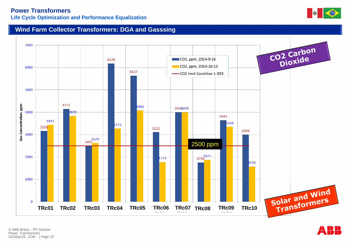
© ABB Brasil – PP DivisionPower Transformers2015Apr23, JCM - | Page 37
2500 ppm
Power TransformersLife Cycle Optimization and Performance Equalization
TRc01 TRc02 TRc03 TRc04 TRc05 TRc06 TRc07 TRc08 TRc09 TRc10
Wind Farm Collector Transformers: DGA and Gasssing

© ABB Brasil – PP DivisionPower Transformers2015Apr23, JCM - | Page 38
Renewables Energy and Transformers ApplicationsLife Cycle – Performance, Reliability and Failure Modes

© ABB Brasil – PP DivisionPower Transformers2015Apr23, JCM - | Page 39
voltageover-excitation
oil gassaturation
oil and insulationmoisture
actions drying insulation degassing oil WTG voltage controlTransf TAPS adjustments
oil, core, windingtemperature reduction
Replace Motor Fans D800Temperature Controlled
oil & insulation condition monitoringby a Hydran M2
daily load variation
WFarm Coll Tr01WFarm Coll Tr02WFarm Coll Tr03
load, MVA
Power Factor, puLoad Factor, ONAF2, pu
l
CollectorTransf TR03
Power TransformersLife Cycle and Failure Mode

© ABB Brasil – PP DivisionPower Transformers2015Apr23, JCM - | Page 40
Dielectric Inter-Turn Insulation Failure of LV Winding
reduced inter-turn insulation strength (withstand)
• free water• bubbles• water droplets
low-energy PD
reduced breakdown voltage
Dielectric Inter-TurnInsulation Failure
oil gas saturation
oil and insulation moisture
daily load variation
voltage over-excitation
• free-water formation at reduced temperatures• free water vapor bubbles at load changes• oil and insulation oxidation• increased oil conductivity• water droplets in the oil• reduced PD inception voltage• reduced Insulation Breakdown Voltage
• dissolved gas in oil• free gas bubbles at load changes• reduced PD inception voltage• reduced Insulation Breakdown Voltage
• winding temperature fast reduction• oil temperature slow reduction• water exchange from oil to insulation• free-water and bubbles at oil-insulation interfaces• bubbles formation at reduced temperatures• free water vapor bubbles at load changes• reduced PD inception voltage• reduced Insulation Breakdown Voltage
• magnetic core saturation• high harmonics saturated flux outside the core• overheating and metal hot-spots• oil gassing• water formation• oxidation oil/insulation• moisture increasing
Power TransformersLife Cycle and Failure Mode

© ABB Brasil – PP DivisionPower Transformers2015Apr23, JCM - | Page 41
water in oil
oil gas saturation
• insulation residual moisture at factory• entry during factory preparation for shipment• entry during transportation• moisture condensation over long time storage• moisture condensation in accessories
(conservator – shipped/storage not pressurized)• entry during site assembly• short-vacuum time at site after long time storage• core/winding/insulation heating in operation
water in insulation
• insulation residual moisture at factory• entry during factory preparation for shipment• entry during transportation• moisture condensation over long time storage• entry during site assembly• short-vacuum time at site after long time storage• core/winding/insulation heating in operation
• long time storage• high N2 content trapped in insulation• oil gassing from heated core/winding/metal parts• water and/or moisture vapor• oil/insulation oxidation (ñCO2)• short-vacuum time at site after long time storage
environment
• long time storage under N2 Nitrogen:Ø long time under N2 with in-tank gas variable
pressure (not automatic gas injection system)
• site assembly:Ø standard final processingØ standard vacuum time even after a long time
storage
• long time storage:Ø oil filled
• insulation conditioning:Ø oil samples and tests only 2 months beforeØ oil/insulation not conditioned to energization
• energization:Ø voltage control during a Wind Farm start-upØ connection to a strong HV power systemØ WTG GSU and collector transf tap settingsØ over-excitation
transformer• designed according to the specification• no-load excitation very low margin• full-load excitation very low margin• motor-fans OFF due to control with high
temperature settings keeping• long time storage under N2 with in-tank gas
variable pressure (no-automatic injection system)
oil and core high temperatures
• fans may be OFF due controls high settings• high core and windings hot-spots temperatures
Power TransformersLife Cycle and Failure Mode
Environment and Conditions

© ABB Brasil – PP DivisionPower Transformers2015Apr23, JCM - | Page 42
Renewables Energy and Transformers ApplicationsLife Cycle - Operation Monitoring Optimization

© ABB Brasil – PP DivisionPower Transformers2015Apr23, JCM - | Page 43
Power TransformersLife Cycle and Operation Optmization
Monitoring
On-Line Monitoring and Sensors:
n load – current & voltagen ambient temperaturen top-oil temperaturen winding hotspot temperaturen moisture in oil/solid insulationn gas in oil H2, CO, C2H4, C2H2 (Hydran)n HV OIP cond bushings C1 & tand
ABB TECüs
üs
üs
! !
üs
MinimumSensors
üs
üs

© ABB Brasil – PP DivisionPower Transformers2015Apr23, JCM - | Page 44
Renewables Energy and Transformers ApplicationsLife Cycle – Advanced Asset Managment
© ABB Brasil – PP DivisionPower Transformers2015Apr23, JCM - | Page 45
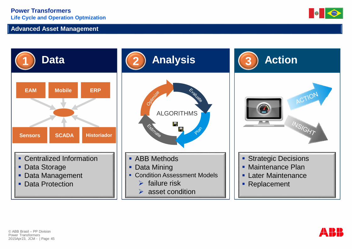
Advanced Asset Management
ActionAnalysisData1 2 3
EAM Mobile ERP
Sensors SCADA Historiador
§ Strategic Decisions§ Maintenance Plan§ Later Maintenance§ Replacement
§ Centralized Information§ Data Storage§ Data Management§ Data Protection
ALGORITHMS
§ ABB Methods§ Data Mining§ Condition Assessment ModelsØ failure riskØ asset condition
Power TransformersLife Cycle and Operation Optmization

© ABB Brasil – PP DivisionPower Transformers2015Apr23, JCM - | Page 46
Advanced Operational BI
Data Processing andAnalytics
Subject Matter Workbench
Enterprise Asset and WorkManagement
Engineering Workbench
Complete InformationFleet to Equipment HealthActionable NotificationsBusiness Process WorkflowOptimization &Planning
Enterprise DataSources
Advanced Asset Management
Power TransformersLife Cycle and Operation Optmization

© ABB Brasil – PP DivisionPower Transformers2015Apr23, JCM - | Page 47
Advanced Asset Management - Potential Benefits
Power TransformersLife Cycle and Operation Optmization

© ABB Brasil – PP DivisionPower Transformers2015Apr23, JCM - | Page 48
Advanced Asset Management - Monitor
Power TransformersLife Cycle and Operation Optmization

© ABB Brasil – PP DivisionPower Transformers2015Apr23, JCM - | Page 49
Advanced Asset Management - Monitor
Power TransformersLife Cycle and Operation Optmization

© ABB Brasil – PP DivisionPower Transformers2015Apr23, JCM - | Page 50
Advanced Asset Management – Maintenance Planning
Power TransformersLife Cycle and Operation Optmization

© ABB Brasil – PP DivisionPower Transformers2015Apr23, JCM - | Page 51
Renewables Energy and Transformers ApplicationsConclusions

© ABB Brasil – PP DivisionPower Transformers2015Apr23, JCM - | Page 52
Conclusions§ technology is now available for economic Wind and Solar power production§ renewables energy power generation are fast moving up in Peru and SAM§ up to 2016 renewables energy to be 5% of power source in Peru§ Wind and Solar together Hydro and Natural gas forming Hybrid Power Plants§ renewables energy bring demand for power transformers§ specific requirements are established for such transformers applications§ transformers key aspects:
Ø environmental friendlyØ advanced technology applicationØ long useful life minimum 30 yearsØ high reliability and availability at minimum maintenanceØ intelligent monitoring and advanced asset managementØ optimum overall life cycle
§ demand for a partner with a solid and experienced technology
Power TransformersLife Cycle Optimization and Performance Equalization
Renewables Energy Transformers
