astronomia de · ... fez exigências rigorosas quanto à qualidade do céu nocturno na região em...
TRANSCRIPT
0

1
ASTRONOMIA DE AMADORES
Revista de divulgação astronómica (n.º 43) — Julho/Dezembro — ano 2012 Propriedade: Associação Portuguesa de Astrónomos Amadores (APAA); P.C. n.º 501 213 414. Sede: Rua Alexandre Herculano, 57- 4.º Dto., 1250 - 010 Lisboa (telefone: 213 863 702) email: [email protected] http://apaaweb.com/
REPRODUÇÃO PROIBIDA, EXCEPTO SOB AUTORIZAÇÃO EXPRESSA DA DIRECÇÃO DA APAA. AS REFERÊNCIAS E AS CITAÇÕES DEVEM INDICAR EXPLICITAMENTE A ORIGEM.
REVISTA ASTRONOMIA DE AMADORES
Equipa redactorial: Pedro Ré, Guilherme de Almeida. Periodicidade: Semestral Distribuição: a Revista ASTRONOMIA DE AMADORES é distribuída gratuitamente a todos os associados que à data da publicação do respectivo número estejam em pleno gozo dos seus direitos, assim como aos sócios honorários e membros do Conselho Técnico e Científico. Conselho Técnico e Científico: Alcaria Rego, Alfredo Pereira, António Cidadão, António da Costa, Cândido Marciano, Carlos Saraiva, Guilherme de Almeida, José Augusto Matos, Pedro Ré e Rui Gonçalves. Colaboraram neste número: Pedro Ré, Guilherme de Almeida, Vitor Quinta. Artigos para publicação: Os trabalhos destinados a publicação, devem ser fornecidos em formato Word 7 ou anterior, acompanhados de memorando explicitando o fim a que se destinam e sendo o conteúdo da responsabilidade dos autores. Só serão aceites trabalhos originais. Os artigos destinados a publicação serão previamente apreciados por um ou mais membros do Conselho Técnico e Científico ou da Redacção que, caso entendam necessário, incluirão nota devidamente assinalada. A APAA encoraja os seus sócios (e até os não sócios) a enviar artigos. Estes traduzem a opinião dos autores, e não necessariamente os pontos de vista da APAA.
ASSOCIAÇÃO PORTUGUESA DE ASTRÓNOMOS AMADORES (APAA) Direcção Presidente: Pedro Ré; Vice-Presidente: Carlos Saraiva; Tesoureiro: Pedro Figueiredo; Secretário: Vítor Quinta; Secretário-Adjunto: Raimundo Ferreira. Mesa da Assembleia-Geral Presidente: António Magalhães; Secretário: Rui Gonçalves; Vogal: José Egeia. Conselho Fiscal Presidente: José Cardoso Moura; Vogal: Paulo Coelho; Vogal: Miguel Claro. Pagamento de quotas 2ª a 5ª feira: das 10 h às 13 h e das 15 h às 19 h; Pagamentos em cheque cruzado à ordem da APAA, vale postal ou transferência bancária. Novos sócios: Para se inscrever na APAA, basta enviar por carta, ou entregar pessoalmente na sede, uma folha A4 contendo nome, morada, data de nascimento, habilitações literárias e endereço e-mail (caso tenha), acompanhado de meio de pagamento da inscrição (5 Euros) e das quotas de pelo menos um trimestre (6 Euros). A quota mensal é de 2 Euros/mês. Os jovens até 25 anos têm uma redução das quotizações de 50%. Em http://apaaweb.com/ existe um formulário de inscrição on-line que poderá facilitar todo este processo.
OBSERVATÓRIO APAA Este observatório resulta de um protocolo estabelecido entre a APAA e o Planetário Calouste Gulbenkian. Denomina-se "Observatório Comandante Conceição Silva" e encontra-se anexo ao Planetário em Belém, junto ao Mosteiro dos Jerónimos.
2
ÍNDICE 3 Determinação da magnitude limite nos céus da região do Alqueva
GUILHERME DE ALMEIDA 6 Determinação analítica do "seeing" utilizando o software DIMM (Differential
Image Motion Monitor) VITOR MANUEL BRITO QUINTA
14 A sombra da Terra e o arco anticrepuscular
GUILHERME DE ALMEIDA 16 Sobre o tamanho aparente da Lua no horizonte e a maiores alturas
GUILHERME DE ALMEIDA 21 The original Crayford Focuser
PEDRO RÉ 24 Barnard’s Photographic Atlas of Selected Regions of the Milky Way
PEDRO RÉ 34 William Lassell’s (1799-1880) Telescopes and the discovery of Triton
PEDRO RÉ 38 James Nasmyth’s (1808-1890) Telescopes
PEDRO RÉ
Imagem da Capa SUN (March, 2012). LUNT152, LUNT60, AT80, DMK41 Pedro Ré (2012) http://re.apaaweb.com/

3
DETERMINAÇÃO DA MAGNITUDE LIMITE
NOS CÉUS DA REGIÃO DO ALQUEVA
Guilherme de Almeida g.almeida(a)vizzavi.pt
Já existe em Portugal uma "região demarcada de céu escuro". Chama-se
Reserva Dark Sky Alqueva e estende-se por 3000 km2, ao longo de seis
municípios: Moura, Mourão, Portel, Reguengos de Monsaraz, Alandroal e
Barrancos. Como afirmar não basta, é preciso certificar, independentemente e a nível internacional. A Fundación Canaria Starlight (ligada ao Instituto de
Astrofísica das Canárias) fez exigências rigorosas quanto à qualidade do céu nocturno na região em apreço, para a poder certificar como destino turístico de
observação astronómica. Para responder a estas exigências foi indispensável (além de outras medições) realizar trabalhos de campo para determinação da
magnitude limite visível a olho nu, abreviadamente designada como NELM
(Naked Eye Limiting Magnitude), em duas localidades desta região.
Condições de escolha dos locais
Considerando que estas determinações da NELM foram feitas precisamente nas mesmas datas em que se fizeram medições do seeing local (estas últimas feitas pelo Eng.º Vítor Quinta), os locais
escolhidos precisavam de ter uma tomada de corrente eléctrica disponível. Tal necessidade levou à
escolha das duas localidades seguidamente indicadas e a uma outra de que se falará depois. As medições foram feitas nas noites de 28 e 29 de Novembro de 2011, em ambientes escuros
envolventes (ou nas traseiras) de hotéis rurais. Estamos conscientes de que esta escolha coloca alguns limites à escuridão do céu, portanto os resultados obtidos, embora muito bons, não
representam o melhor que o Alqueva tem para oferecer em termos de céu escuro. Por outras
palavras, a escassos quilómetros dos locais testados é possível encontrar outros lugares na região, onde a magnitude limite seja ainda mais alta do que a medida nestes trabalhos de campo. Apesar
disso, mesmo nestes locais menos ideais, os resultados obtidos levaram à determinação de magnitudes limite de 6,0 ou até melhor (6,3).
Em consequência dos resultados das medições de NELM, de seeing e da magnitude do céu por
segundo de arco quadrado, abreviadamente "MPSAS" (veja-se a nota final 1), a Reserva Dark Sky
Alqueva foi a primeira a ser certificada a nível mundial pela "Fundación Canaria Starlight", organização ligada ao Instituto de Astrofísica das Canárias (IAC).
Através destas nossas determinações da NELM e "seeing", no âmbito de um protocolo de colaboração já celebrado entre a APAA e a Genuineland (entidade fundadora e coordenadora da
Reserva Dark Sky Alqueva), a APAA teve um papel essencial num projecto nobre e admirável. A
Genuineland é presidida pela Dra Apolónia Rodrigues, que viu neste projecto uma causa a defender.
Método
As determinações da magnitude limite foram feitas utilizando o método e os procedimentos
preconizados pela IMO (International Meteor Organization) contando o número de estrelas visíveis dentro de campos de estrelas bem especificados e delimitados. O procedimento completo para a
determinação da magnitude limite pelos métodos da IMO pode ser consultado em:
http://www.saguaroastro.org/content/db/limit-mag.pdf
Resultados
Os resultados obtidos foram desenvolvidos nas páginas seguintes e sintetizados nos
correspondentes quadros. A "NELM" foi abreviada nos quadros como "mL" (magnitude limite).

4
1. Medições no Monte de Santa Catarina
O Monte de Sta Catarina é um local aprazível de turismo rural, localizado a cerca de 12 km da
pequena cidade Reguengos de Monsaraz. Aí temos um céu majestoso e magnífico, amplo e desimpedido.
Quando a Lua não é visível, a galáxia M31 é ali um objecto óbvio a olho nu. O céu é muito escuro e consegue-se detectar M33 sem qualquer ajuda óptica, assim como famoso enxame duplo do Perseu
(NGC 884 e NGC 889), os enxames abertos do Cocheiro e alguns outros objectos do céu profundo.
Mas o mais incrível é que, com um céu desta qualidade, basta andar duas ou três dezenas de metros para entrar num quarto com todas as comodidades necessárias, conforto térmico, televisão e
Internet. Ou desfrutar de uma ceia às horas tardias a que as observações por vezes nos levam. Os astrónomos amadores são bem vindos e a simpatia é a nota dominante. É a mesma família que
dirige o Monte de Santa Catarina e o Monte Alerta, a escassos 300 m e com um céu igualmente bom.
Quem dirige estes dois montes é também entusiasta das observações astronómicas. Existe no local um telescópio newtoniano de 12 polegadas (D=305 mm, f/5). Pode ser utilizado na
forma dobsoniana ou em montagem equatorial com goto.
Monte de Sta Catarina: http://www.montesantacatarina.com/pt/component/content/article/46
Localização: Latitude: 38º 26' 53.67" N; Longitude: 7º 21' 54.98" W; Altitude: 188 m.
Determinação da magnitude limite (mL) no Monte de Santa Catarina
Campo de estrelas IMO N.º
Estrelas nos vértices do
campo
Estrelas contadas pelo observador A
e (mL)
Estrelas contadas pelo observador
e B (mL)
Média das magnitudes limite A B
Média global (mL)
2
Persei
Persei
Persei
12 (mL=6,0)
14 (mL=6,1
6,0
6,2 8
Tauri
Tauri
Tauri
15 (mL=6,2)
18 (mL=6,4)
6,3
2. Medições no hotel de turismo rural Nave Terra
A "Nave Terra" é um hotel de turismo rural localizado a 7 km do Alandroal e a cerca de 60 km de Évora. O céu é bastante escuro e alguns objectos do céu profundo são detectáveis sem ajuda óptica.
O céu é imponente e desimpedido em praticamente todos os azimutes. Podemos instalar um telescópio a menos de 30 m do quarto onde ficamos. A gerência é simpática, afável e acolhedora.
Determinação da magnitude limite (mL) no hotel de turismo rural "Nave Terra"
Campo de estrelas IMO N.º
Estrelas nos vértices do
campo
Estrelas contadas pelo observador A
e (mL)
Estrelas contadas pelo observador B
e (mL
Média das magnitudes limite A B
Média global (mL)
2
Persei
Persei
Persei
11 (mL=5.7)
13 (mL=6,0
5,9
6,0 8
Tauri
Tauri
Tauri
11 (mL=6.0)
13 (mL=6,1)
6,1
Nave Terra é um nome que nos recorda a Terra como nave espacial, viajando pelo espaço a cerca
de 250 km/s em torno do centro da Via Láctea. É também o nome da herdade onde se situa.
Nave Terra: http://www.hotelnaveterra.com/
Localização: Latitude: 38º 42' 16.39" N; Longitude: 7º 20' 06.56" W; Altitude: 249 m.
5
Na ocasião das medições o ar não estava muito transparente. Nuvens finas, atmosfera húmida e uma ligeira neblina podem ter comprometido a detecção visual de estrelas muito ténues. Tal
contribuiu certamente para que a extinção fosse um pouco superior à que seria registada com ar mais
seco, e consequentemente para uma ligeira redução da magnitude limite.
3. Determinação intencional da magnitude limite num caso desfavorável
Para além das determinações feitas em locais de céu escuro, foi decidido avaliar uma situação
muito especial, para o que seria quase o "pior caso possível" na região. Com esse objectivo determinou-se a magnitude limite, seguindo os mesmos métodos, bem no coração de uma sede de
município (> 8500 pessoas), ou seja, dentro na vila de Portel, na noite de 28 de Novembro de 2011. Procurámos, assim, verificar quanto perderia o observador mais comodista que fizesse as suas
observações bem dentro de uma vila de razoável dimensão, na região da Reserva. As determinações
foram feitas no Hotel Refúgio da Vila, simpático e muito acolhedor, situado num local iluminado, no núcleo de Portel. Escolhemos, dentro do recinto do hotel, um espaço relvado, nas traseiras, seguro e
abrigado de luzes excessivas. É claro que estamos bem conscientes dos efeitos devastadores que um local assim pode ter na
escuridão do céu. Num local com estas características não podemos esperar excelentes valores da
magnitude limite detectável a olho nu. Fizemos este exercício de campo para ver até que ponto um local povoado e com poluição luminosa já muito significativa se comporta em termos de qualidade do
céu. Na verdade, com todos estes "maus requisitos", os resultados obtidos surpreenderam-nos. Obtivemos uma magnitude limite de 5,8 que poderia ser ainda superior se a humidade do ar (naquela
noite específica) tivesse sido menor. Os resultados obtidos foram sintetizados no quadro seguinte.
Determinação da magnitude limite (mL) na vila de Portel (sede de município)
Campo de estrelas IMO N.º
Estrelas nos vértices do
campo
Estrelas contadas pelo observador A
e (mL)
Estrelas contadas pelo observador B
e (mL))
Média das magnitudes limite A B
Média global (mL)
2
Persei
Persei
Persei
9 (mL=5.5)
9 (mL=5,5)
5,5
5,8 8
Tauri
Tauri
Tauri
10 (mL=5.9)
11 (mL=6,0)
6,0
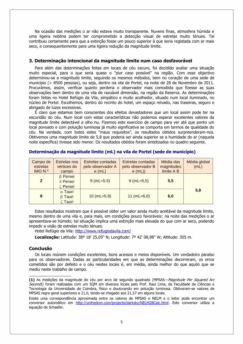
Estes resultados mostram que é possível obter um valor ainda muito aceitável da magnitude limite, mesmo dentro de uma vila e, para mais, em condições pouco favoráveis: na noite das medições o ar
apresentava-se húmido; tal situação implica uma extinção mais elevada do que com ar seco, podendo
impedir a visão de estrelas muito ténues. Hotel Refúgio da Vila: http://www.refugiodavila.com/
Localização: Latitude: 38º 18' 25,05" N; Longitude: 7º 42' 08,98" W; Altitude: 305 m.
Conclusão
Os locais reúnem condições excelentes, bons acessos e meios disponíveis. Um verdadeiro paraíso para os observadores. Dadas as particularidades em que as determinações decorreram, os erros cometidos são por defeito e o céu nestes locais é, em média, ainda melhor do que aquilo que se
mediu neste trabalho de campo.
___________________
(1) As medições da magnitude do céu por arco de segundo quadrado (MPSAS—Magnitude Per Squared Arc Second)) foram realizadas com um SQM em diversos locais pelo Prof. Raul Lima, da Faculdade de Ciências e Tecnologia da Universidade de Coimbra, físico e doutorando em poluição luminosa. Obtiveram-se valores de MPSAS regra geral superiores a 21,0, tendo-se chegado aos 21,57 em alguns locais.
Existe uma correspondência aproximada entre os valores de MPSAS e NELM e o leitor pode encontrar um conversor automático em http://unihedron.com/projects/darksky/NELM2BCalc.html. Este conversor utiliza a equação de Schaefer.

6
DETERMINAÇÃO ANALÍTICA DO "SEEING"
UTILIZANDO O SOFTWARE DIMM
(DIFFERENTIAL IMAGE MOTION MONITOR) Vitor Manuel Brito Quinta [email protected]
A maior parte dos astrónomos amadores, senão todos, estarão familiarizados com a noção do
"seeing" e do que isso significa, não só para quem se dedica apenas à observação visual mas,
sobretudo, para quem faz astrofotografia. O termo "seeing" é um estrangeirismo que já se tornou de uso habitual entre nós, embora se possa usar o termo português "visão". Seguidamente será referido
como seeing.
O seeing dá-nos boas indicações sobre o grau de turbulência da atmosfera existente no nosso local de observação e, com essa grandeza quantificada, sabemos, por exemplo, se podemos esperar uma
sessão de observação em que as estrelas duplas são facilmente separáveis, ou se vale a pena
fazermos um video de um qualquer planeta que esteja alto no céu. A atmosfera actua como uma lente que, continuamente, deforma a imagem obtida através da
objectiva de um telescópio, deteriorando a sua qualidade. Este efeito do seeing está sempre presente em maior ou menor grau, mas existem locais na Terra onde, na maior parte do tempo, se faz sentir
com muito menor intensidade, e esses locais são naturalmente procurados para a instalação dos
observatórios profissionais, como sejam os Andes Chilenos, as ilhas Canárias, o Hawai, etc.
Quase, invariavelmente, são locais a grande altitude (acima dos 2000 m) e junto ao mar, pois o oceano faz com que as várias camadas da atmosfera se mantenham relativamente estáveis e planas,
proporcionando imagens bem contrastadas (Fig.1).
Fig.1
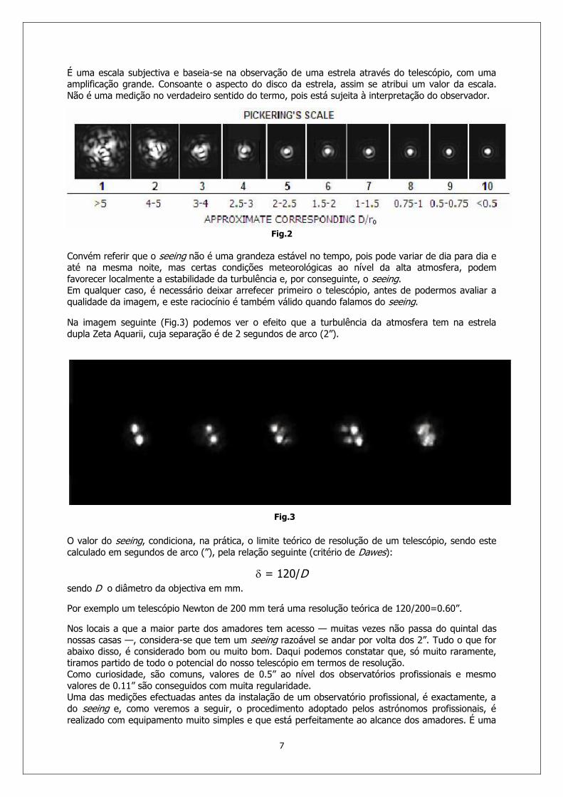
Uma das formas de avaliar o seeing, qualitativamente, deve-se ao astrónomo William H. Pickering (1858-1938), do Observatório de Harvard e ficou com o nome de escala de Pickering. Nela
encontramos enumerados de 1 a 10, níveis de qualidade do “seeing”, sendo 1 a pior e 10 a melhor (Fig.2).
7
É uma escala subjectiva e baseia-se na observação de uma estrela através do telescópio, com uma amplificação grande. Consoante o aspecto do disco da estrela, assim se atribui um valor da escala.
Não é uma medição no verdadeiro sentido do termo, pois está sujeita à interpretação do observador.
Fig.2
Convém referir que o seeing não é uma grandeza estável no tempo, pois pode variar de dia para dia e até na mesma noite, mas certas condições meteorológicas ao nível da alta atmosfera, podem
favorecer localmente a estabilidade da turbulência e, por conseguinte, o seeing. Em qualquer caso, é necessário deixar arrefecer primeiro o telescópio, antes de podermos avaliar a
qualidade da imagem, e este raciocínio é também válido quando falamos do seeing.
Na imagem seguinte (Fig.3) podemos ver o efeito que a turbulência da atmosfera tem na estrela
dupla Zeta Aquarii, cuja separação é de 2 segundos de arco (2”).
Fig.3 O valor do seeing, condiciona, na prática, o limite teórico de resolução de um telescópio, sendo este
calculado em segundos de arco (”), pela relação seguinte (critério de Dawes):
= 120/D
sendo D o diâmetro da objectiva em mm.
Por exemplo um telescópio Newton de 200 mm terá uma resolução teórica de 120/200=0.60”.
Nos locais a que a maior parte dos amadores tem acesso — muitas vezes não passa do quintal das
nossas casas —, considera-se que tem um seeing razoável se andar por volta dos 2”. Tudo o que for abaixo disso, é considerado bom ou muito bom. Daqui podemos constatar que, só muito raramente,
tiramos partido de todo o potencial do nosso telescópio em termos de resolução. Como curiosidade, são comuns, valores de 0.5” ao nível dos observatórios profissionais e mesmo
valores de 0.11” são conseguidos com muita regularidade. Uma das medições efectuadas antes da instalação de um observatório profissional, é exactamente, a
do seeing e, como veremos a seguir, o procedimento adoptado pelos astrónomos profissionais, é
realizado com equipamento muito simples e que está perfeitamente ao alcance dos amadores. É uma

8
medição que, no caso dos observatórios profissionais, tem de ser feita de uma forma contínua e regular ao longo do ano, com equipamento fixo e numa estrutura própria.
O projecto "Reserva Dark Sky Alqueva ®"
Desde o primeiro momento, a APAA foi convidada a participar nas reuniões de trabalho, para a
implementação de um projecto turístico denominado “Reserva Dark Sky Alqueva” com uma componente astronómica, na região abrangida por seis concelhos do Alentejo, junto ao Alqueva,
respectivamente, Portel, Reguengos de Monsaraz, Barrancos, Alandroal, Moura e Mourão. No seguimento, foi estabelecido um protocolo de colaboração entre a APAA e a Genuineland, rede
de turismo de aldeia do Alentejo, entidade coordenadora do projecto.
A atribuição da denominação de "Reserva Dark Sky ®" obrigava à determinação de vários parâmetros
objectivos de qualidade do céu, após o que — caso os requisitos de qualidade fossem atingidos—
seria atribuída a certificação pela “Fundación Canaria Starlight” entidade ligada ao Instituto Astrofísico
das Canárias (IAC). Um desses parâmetros era a determinação do “seeing” com um valor menor ou igual a 2”, algo que
na altura pensámos ser exagerado, para um local turístico. Como não estávamos ao corrente da técnica necessária (DIMM) para avaliação deste parâmetro, reunimos, eu e o Prof. Guilherme de
Almeida, com duas responsáveis do IAC, que nos informaram — embora superficialmente — dos procedimentos a adoptar.
Numa busca mais aprofundada na net sobre DIMM, constatou-se que era relativamente simples a medição do seeing com equipamento acessível à maior parte dos amadores. Foi-nos ainda
recomendado, que o software a utilizar, só poderia ser este:
http://www.alcor-system.com/us/DimmSoftware/index.html
É um software pago, mas que pode ser usado gratuitamente, a título experimental e com todas as
suas funcionalidades, durante 30 dias. O site traz informações muito úteis, também, sobre a teoria por detrás do DIMM, cuja leitura recomendo aos mais interessados.
A firma SBIG comercializa, ou comercializava, um equipamento de medição directa do “seeing”, através da estrela polar, mas este não foi aceite pelos responsáveis do IAC.
O que o software faz é medir o FWHM (Full Width at Half Maximum) da imagem de uma estrela
ligeiramente desfocada, cuja luz passa por uma máscara com duas aberturas, colocada na pupila de
entrada de um telescópio. Adiante falaremos dos requisitos que esta máscara deve cumprir. A figura de difracção de uma estrela no plano focal de um telescópio é, em condições de excelente
seeing, um disco luminoso minúsculo e brilhante (denominado disco de Airy), rodeado por anéis alternadamente escuros e claros, progressivamente mais ténues.
O FWHM é um valor estatístico em segundos de arco, representativo do diâmetro do disco da figura
de difracção entre o seu valor máximo de intensidade luminosa e a metade desse valor.
Neste caso, em que desfocamos a estrela e onde o seeing está longe de ser excelente, temos duas imagens da mesma estrela em movimento contínuo, pois a frente de onda incidente, passa pelas duas
aberturas, com inclinação e curvatura diferentes, distorcendo as duas imagens obtidas de forma diferente. O software mede continuamente o desvio relativo — daí a designação de “differential” —,
entre as duas imagens segundo dois eixos perpendiculares. Quaisquer erros de guiagem, vibrações ou
de outra natureza, são assim eliminados do processo de medição. Após o cálculo do FWHM nas duas direcções perpendiculares, o software apresenta automaticamente o valor do seeing em segundos de
arco. Para efectuar esta medição, são necessários, para alem da já referida máscara, uma câmara de vídeo
— uma velhinha Toucam serve perfeitamente — que consiga produzir exposições de 1/50 s ou menos, e um telescópio que, por considerações práticas, deverá ter uma abertura igual ou superior a 200
mm.
As únicas condições para as duas aberturas da máscara são:

9
a) a distância entre os seus centros tem de ser maior ou igual ao dobro do seu diâmetro;
b) não podem, obviamente, ser obstruídas pelos limites da célula do secundário nem pelas patas
da aranha deste, no caso de um telescópio newtoniano;
Assim para um telescópio de 200 mm e duas aberturas de 60mm, a distância entre os seus centros deverá ser maior ou igual a 120 mm (Fig.4).
Com tempos de exposição tão curtos, deverá ser escolhida uma estrela brilhante junto ao zénite ou
próximo, o que nem sempre é possível, dependendo da altura do ano; no entanto escolhendo a hora conveniente ao longo da noite, tal requisito pode ser conseguido. O brilho da estrela escolhida
condiciona a abertura mínima do telescópio a usar, bem como a sua distância focal, assim como a
dimensão mínima das aberturas a praticar na máscara, para se obter duas imagens (da mesma estrela) com uma boa relação sinal/ruído.
Após um mínimo recomendado de 50 frames, o software calcula o “seeing” e, em cada medição, vai
construindo um gráfico com estes valores, até que demos por concluída a nossa medição.
Antes de realizarmos o nosso trabalho de campo, fiz alguns testes com o meu equipamento e uma Toucam, no meu quintal, para me familiarizar com o processo e detectar eventuais dificuldades.
Testei-o com um Meade Schmidt-Cassegrain de 250 mm f/10 e com um newtoniano de 200 mm f/4 e,
em noites consecutivas, os resultados foram muito semelhantes.
Fig.4. O telescópio preparado já com a máscara (à esquerda). À direita mostra-se uma representação
à escala das aberturas da máscara e da distância entre centros (para o telescópio indicado).
60 mm
130 mm
60 mm

10
As medições de seeing
Finalmente, conseguiu-se uma janela de oportunidade nos dias 28 e 29 de Novembro de 2011, e fomos, eu e o Prof. Guilherme de Almeida, para a região do Alqueva fazer a medição do seeing, com o
meu equipamento, um telescópio newtoniano de 200 mm f/4 e uma Toucam Pro, em cima de uma equatorial GP-DX motorizada nos dois eixos. A máscara tinha duas aberturas de 60 mm, cujos centros
estavam afastados de 130 mm.
Os resultados obtidos nas localidades do Alandroal e Monsaraz, com as estrelas Mirphak ( Per) e
Alnath ( Tau) respectivamente, são ilustrados com as imagens seguintes (capturas de ecrã, obtidas
com a tecla do PrintScreen) e permitiram concluir que o seeing esteve abaixo dos 2”, pelo menos
durante o intervalo que demorou cada medição.
O programa, a pedido do utilizador, cria ficheiros de texto de todos os valores calculados, durante intervalos bem definidos ou para todo o intervalo da medição. Por serem ficheiros muito extensos,
não foram incluídos neste artigo. Os resultados destas medições, bem como dos restantes parâmetros
exigidos, foram enviados para a “Fundación Canaria Starlight” que os validou, e a certificação chegou antes do final do ano, com documento oficial a comprová-lo. A região do Alqueva tornou-se assim, na
primeira do mundo a obter uma certificação do céu.
Medições no ALANDROAL (Hotel Nave Terra):

11
ALANDROAL (continuação)
Para poder determinar o seeing, o programa DIMM pede ao utilizador, pelo menos, o preenchimento dos dados seguintes:
- Distância focal do telescópio (no nosso caso 800 mm).
- Diâmetro de cada abertura (no nosso exemplo 60 mm).
- Distância entre os centros das aberturas (no nosso exemplo 130 mm).
- Dimensão do pixel da câmara, em µm (no caso da Toucam será 5.6 µm).
- Comprimento de onda da luz a utilizar na medição (usualmente 0.50 µm, ou seja, 500 nm).

12
Medições em MONSARAZ (Monte St. Catarina)

13
MONSARAZ (continuação)

14
A SOMBRA DA TERRA E O ARCO
ANTICREPUSCULAR
Guilherme de Almeida
Qualquer corpo iluminado pelo Sol projecta uma sombra para o correspondente lado oposto. E o nosso planeta não escapa a essa regra: à tarde e ao cair da noite podemos ver a sombra da terra
projectada no único alvo suficientemente grande para a conter: a atmosfera. Devido às partículas em suspensão, a nossa atmosfera pode funcionar como um enorme ecrã.
Cerca de meia hora após o ocaso solar, quando o céu está limpo, basta olhar para este, na
direcção oposta àquela onde o Sol se escondeu, para ver a sombra terrestre (Fig. 1). De manhã, cerca
de meia hora antes do nascer do Sol, também a podemos ver, olhando para oeste. Veremos seguidamente como é que se fazem essas observações.
A sombra da Terra e a cintura de Vénus
A sombra da Terra, tal como a podemos ver, tem a forma de uma enorme banda que se estende cerca de 180º em largura, centrada no ponto anti-solar (veja-se a nota 1). Esta sombra é
nitidamente mais escura do que o céu crepuscular e tem uma tonalidade azul-ardósia, de contorno
esbatido.
A sombra é vista como uma banda porque, dadas as suas dimensões e a pequena parcela do seu contorno que se pode avistar de cada local, tal contorno pouco difere de um segmento de recta. A
sombra da Terra é rodeada por um halo rosado, vulgarmente conhecido como "cintura de Vénus" ou "arco anticrepuscular", por oposição ao arco crepuscular que se desenvolve no horizonte por cima do
Sol, pouco depois do seu ocaso (Fig. 2). Esta luminosidade rosada, que se difunde na atmosfera,
provém da luz do Sol que se põe, ou que nasce, sobre as camadas gasosas que se encontram por cima de nós, na alta atmosfera.
Fig.1. Formação da sombra da Terra e do arco anticrepuscular. A figura não está representada à escala e a indicação "Sol" refere-se apenas à direcção de onde vêm os raios solares e não à posição do Sol nem às suas dimensões efectivas. Guilherme de Almeida (2011).

15
Pouco depois do Sol se pôr, a sombra da Terra surge a este, ainda baixa, mas vai subindo
lentamente à medida que o Sol desce. Vinte minutos após o ocaso, a sombra já está bem mais alta e atinge cerca de 10º de altura na direcção antisolar; o arco anticrepuscular é agora mais largo, mas
mais esbatido, pois a sua coloração rosada vai-se diluindo. A sombra da Terra pode ser vista até cerca de vinte graus de altura, meia hora após o caso, mas a cintura de Vénus já será muito ténue. Pela
noite, na meia hora que se segue ao pôr do Sol, assistimos pouco a pouco ao escurecimento do céu e
da cintura de Vénus; o escurecimento global do céu oculta então rapidamente a sombra terrestre e a noite cai. Pela madrugada, dá-se o fenómeno inverso: a sombra terrestre ergue-se lentamente sobre
o horizonte oeste e o arco anticrepuscular adorna harmoniosamente o seu limite superior, até ao nascer do Sol.
Os raios anticrepusculares
É frequente que no ponto anti-solar se possam ver raios solares a convergir, o que tem a ver com
a aparência esférica do céu que nos rodeia. Embora a luz do Sol percorra de facto linhas rectas, as projecções destas linhas num céu esférico
aparente são grandes arcos de circunferência, que voltam (aparentemente)
a convergir do lado oposto, tal como a
separação entre os gomos de uma laranja (Fig. 3). Por isso, os raios crepusculares de
um pôr do Sol parecerão convergir no ponto anti-solar, do lado oposto. E também ao
nascer do Sol os raios crepusculares
parecerão voltar a convergir no outro lado do céu. No ponto anti-solar, a 180º do Sol, estes
raios são referidos como raios anticrepusculares.
________________ (1) – O ponto anti-solar é o ponto da esfera celeste diametralmente oposto àquele onde se encontra o centro do disco solar. Em relação à esfera celeste, o ponto anti-solar move-se lentamente para este, em consonância com o movimento aparente anual do Sol.
Fig.2. Simulação do aspecto observável da sombra da Terra e do arco anticrepuscular. A tonalidade da sombra pode ser subtil e o arco anticrepuscular pode parecer difuso, mas são inconfundíveis para um observador atento. Guilherme de Almeida (2011).
Fig.3. Magnífica imagem dos raios anticrepusculares sobre o horizonte este. Parece uma fotografia banal, mas o Sol não está à nossa frente: está nas nossas costas, a oeste! Fotografia de Daniel Herron (www.danielandmisty.com), obtida na Florida, Estados Unidos da América, em Setembro de 2006. Imagem utilizada com a autorização do autor.

16
SOBRE O TAMANHO APARENTE DA LUA NO
HORIZONTE E A MAIORES ALTURAS
Guilherme de Almeida [email protected]
É frequente afirmar-se que a Lua nos parece maior quando desponta no horizonte e menor quando a vemos mais alta. Todos nos apercebemos disso, mas será realidade, ilusão ou pura confusão? No
presente artigo analisaremos a variação da distância da Lua ao observador, quando ela é observada a
diferentes alturas no mesmo dia, e procuraremos uma explicação para esses factos.
Apreciação do problema
É certo que devido à orbita elíptica da Lua em torno da Terra, descrita em cerca de 27,3 dias, o nosso satélite passa por uma posição mais próxima da Terra (perigeu), onde nos parece maior, e por
outra mais afastada (apogeu), onde é vista com menor diâmetro aparente (figura 5). Isso é real e
mensurável, mas o objecto deste artigo é outro: referimo-nos à diferente percepção visual do diâmetro aparente da Lua, na mesma noite, a diferentes alturas em relação ao horizonte. Na verdade,
em pouco mais de 5 horas, desde que a Lua nasce até que atinge a sua altura máxima na mesma noite, a distância da Terra à Lua (que é sempre entendida entre os centros destes dois astros) pouco
varia. Por isso podemos considerar, sem grande erro, tal distância como constante para um intervalo
de tempo tão curto (menos de 1/100 do período orbital). Neste contexto é lícito considerar esse troço da órbita da Lua como se fosse circular.
Muitas explicações podem ser adiantadas para a tradicional percepção de uma Lua maior quando esta se encontra junto ao horizonte, a nascente ou a poente. Pura ilusão para alguns, percepção
errónea para outros, ilusão de óptica para outros ainda. Começaremos por ver como varia a distância
da Lua a um observador terrestre, à medida que a Lua nasce até à sua
altura máxima (passagem meridiana). Na figura 1 mostram-se três posições
da Lua em relação a um observador terrestre: No horizonte (H), à distância
dH: do observador; no meridiano (M), à
distância dM; no zénite (Z), à distância dZ do observador, numa situação que
não é possível para a latitude do território português. Por razões de
clareza, a distância da Terra à Lua não
foi representada à escala, embora as dimensões relativas da Terra e da Lua
estejam na mesma escala.
Fig. 1. A Lua no horizonte, no meridiano e no zénite, para um dado observador. R designa a medida do raio terrestre médio e dm indica a distância média, entre centros, da Lua à Terra. O texto dá mais informações (Guilherme de Almeida, 2011).
Na figura 1 podemos ver que dH>dM ou seja, no horizonte, a Lua está mais longe do observador
do que quando se encontra no meridiano. Veja-se ainda que dM>dZ e consequentemente dH>dZ , o que significa que a Lua no meridiano está mais longe do observador do que quando está no zénite; e que
a Lua no horizonte está mais afastada do observador que se estivesse no meridiano. Como o nosso
planeta não é "um ponto" em relação às dimensões da órbita lunar (R/dM1/60), resulta que, para
C
dz
dz
dH
dM
Lua no meridiano
dz Lua no
horizonte
Observador
TERRA
Lua no zénite, quando tal é possível para um dado observador
R
dm

17
idêntica distância entre o centro da Terra e o centro da Lua, as distâncias da Lua em relação ao observador cumprem a relação: distância no horizonte>distância no meridiano>distância no zénite
(dH>dM>dZ). Sabemos que uma distância maior deverá corresponder a um diâmetro aparente menor
(e vice-versa). Nestas condições, o diâmetro aparente da Lua deverá ser máximo no zénite (distância mínima), um pouco menor no meridiano e ainda menor no horizonte. Trata-se de um resultado
surpreendente, contrário às nossas expectativas e ao senso comum: a Lua junto ao horizonte apresenta um diâmetro aparente menor. Porque razão nos parece maior? É o que veremos neste
artigo (veja-se a nota final 1).
Há algumas precauções a tomar nas medições eventualmente necessárias. No que se refere às medições de altura, convém referir que a refracção atmosférica eleva a altura aparente dos astros,
mas essa diferença é pequena para as medições absolutas de altura: tal elevação é de 34' para um astro no horizonte, 9,7' a 5º de altura, de 2,7' a 20º, de 1´a 45º e é nula no zénite. Por esse motivo
não se fizeram correcções de altura; no entanto, a refracção diferencial a alturas muito baixas, muito perto do horizonte, contrai consideravelmente o diâmetro aparente da Lua na vertical: é por isso que
os diâmetros aparentes se devem tomar na horizontal.
Quantificando o problema
Vistas as coisas do lado qualitativo, resta passar à análise quantitativa para saber quanto variam
essas distâncias. E saber se tais diferenças serão ou não significativas. A figura 2 mostra a Terra e a
Lua, com os seus tamanhos relativos à escala, mas a distância entre elas foi representada por metade
do que deveria ser, para que coubesse nesta página. O ângulo =BÂC é na realidade muito pequeno:
para a distância média da Lua à Terra, dm=384 400 km, e para raio terrestre médio R=6373 km,
=0,9498º0,95º. Na verdade, o ângulo recto é o que tem vértice em B. E o ponto B não está na
vertical por cima de C, mas um pouco mais para a direita, devido à obliquidade do segmento BA em relação ao segmento CA. No entanto, essas diferenças são insignificantes e podemos considerar que
BC e BA são praticamente do mesmo comprimento, pois cos 0,95º=0,99986… 1,00000 com erro
inferior a 0,0138% Assim sendo, as direcções de BA e da CA podem ser vistas como se fossem
paralelas, como se mostra na figura 3.
Fig. 2. A Terra e a Lua. Para que tudo ficasse à escala nesta figura, tendo a Terra e a Lua as dimensões representadas, a distância entre os dois astros teria de ser dupla da que aqui se mostra (mas já não caberia nesta página). Portanto, o ângulo ainda é menor (praticamente metade) do que parece nesta ilustração. C e A indicam, respectivamente, o
centro da Terra e o centro da Lua. (Guilherme de Almeida, 2011).
O movimento aparente da Lua no céu (nascimento, passagem meridiana, ocaso) é principalmente
devido à rotação da Terra (veja-se a nota final 2). A figura 3, mostra três posições do mesmo
observador em relação à Lua, em três momentos distintos. Na posição B, o observador vê a Lua no horizonte; em D, vê-a no meridiano, a uma distância zenital z, correspondendo a uma altura h=90º–z; na posição E, o observador vê a Lua no seu zénite (situação impossível para o território português). Fig. 3. A Lua, vista pelo mesmo observador em três situações distintas. A distância entre o observador e a Lua mede-se até ao centro da Lua, dado que o limbo lunar, passando em F e G, é praticamente coincidente com um círculo máximo perpendicular à linha de visão, por razões semelhantes às já indicadas para a figura 2. (Guilherme de Almeida, 2011).
A
C
B
Terra Lua
x=R cos z
Para a Lua
R
z
z
C
B
D
E
A
F
G
18
Como podemos ver na figura 3, quando a Lua passa do horizonte (h0=0º, posição B) para o meridiano do observador (posição D), ela aproxima-se deste uma distância x dada por
x= R cos z , ou seja x= R sin h, [Equação 1]
visto que cos z = sin h (pois h+z=90º); R é o raio terrestre médio: R=6370 km.
Quando a Lua passa no meridiano, a distância zenital lunar (z) é mínima, correspondente a uma
altura máxima (hM). Por outras palavras quando a Lua se eleva desde o horizonte até ao meridiano, a sua distância até ao observador diminui x= R sin h . Ou seja,
dM=dH– R sin hM. [Equação 2]
Escrevendo esta última expressão para uma altura genérica h, obtemos
d=dH– R sin h , [Equação 3]
que nos mostra claramente que d é mínima quando h=90º (Lua no zénite do observador). A mesma figura 3 também mostra que dM – dz = R (1 – sin h).
Alguns casos particulares
Para h=45º e R=6373 km x será aproximadamente 4506 km. Portanto, a Lua no horizonte está
4506 km mais longe do observador do que quando está a ser vista no meridiano. Para a distância média entre centros dos dois astros de 384 400 km, a distância do observador ao centro da Lua, será:
a) com a Lua no horizonte, dH=384 400 km;
b) com a Lua no meridiano, por exemplo a 45º de altura, a distância será
d45=384 400 – 6373 sin 45º= 379 894 km (379 900 km);
c) com a Lua no zénite (se o local do observador o permitir) dZ=dM–R=384 400–6373 = 378 027 km
( 378 000 km); esta situação não é viável no território português, onde a Lua nunca atinge o zénite.
A Lua, a 45º de altura, está 4506 km mais perto do observador do que quando está a ser vista no
horizonte. Posta tal diferença em percentagem, face à distância média da Lua à Terra (384 400 km), será: 4506/384 400=0,0117, ou seja, a distância reduz-se em 1,17% quando a Lua passa do
horizonte (h0=0º) para h=45º. Dado que o diâmetro aparente da Lua é um ângulo pequeno, tal diâmetro aparente é inversamente
proporcional à distância a que ela é observada. Para duas distâncias d1 e d2, sendo a Lua vista sob os
diâmetros aparentes 1 e 2 (respectivamente), pode escrever-se:
1
2
2
1
d
d [Equação 4]
Dito de outro modo, eventualmente mais útil, se a Lua tiver o diâmetro aparente 45= 0,500º a 45º
de altura, com d45=379 894 km, a mesma Lua no horizonte, com dH=384400 km, será vista com um
diâmetro aparente H tal que (384400/379894)=( H/45), ou seja, H=379894x0,5/384400= 0,494º.
Note-se que o diâmetro aparente vertical da Lua é comprimido pela refracção atmosférica terrestre,
sobretudo a pequenas alturas, pelo que é mais sensato tomar os diâmetros aparentes horizontais, que são imunes à refracção diferencial.
Relação entre diâmetros aparentes da Lua para duas alturas quaisquer
Também podemos prever a relação entre os diâmetros aparentes da Lua a duas quaisquer alturas
diferentes, h1 e h2 >h1. Para isso, comecemos por escrever a equação 3 para os casos particulares h1
e h2 :
d1=dH – R sin h1 [Equação 5] e d2=dH – R sin h2 [Equação 6]
Entrando com os valores de d1 e d2 das equações 5 e 6 na anterior equação 4, obtemos imediatamente:

19
1
2
2
1
sin
sin
hRd
hRd
H
H , [Equação 7]
onde dH pode ser tomada como a distância entre a Terra e a Lua no "momento" da observação (como
foi já referido, num intervalo de poucas horas esta distância pouco se altera.
Se a Lua, vista junto ao horizonte, está na realidade mais longe do observador do que quando é observada a maiores alturas, o seu diâmetro aparente terá de ser menor, como acabámos de ver,
mas de facto os observadores têm a convicção de que a vêem maior. Deverá, pois, existir uma
distorção da percepção, ilusão de óptica, ou efeito psicológico (chame-se-lhe o que se quiser) que contraria vantajosamente esta realidade objectiva. A aparente proximidade da Lua em relação ao
horizonte, esteja ele livre (no oceano), pejado de árvores ou de prédios, forma uma referência que perturba a nossa percepção. Um exemplo desta distorção da percepção devido ao efeito de vizinhança
pode ser visto na figura 4.
Fig. 4. Esta figura mostra como o efeito de vizinhança distorce a nossa percepção do diâmetro do círculo laranja. Embora tal círculo seja rigorosamente igual à esquerda e à direita, todas as pessoas pensam que o círculo da direita é maior do que o da esquerda. Guilherme de Almeida (2011).
Se observarmos a Lua através de uma abertura circular (por exemplo com 2 cm ou 3 cm de
diâmetro), numa folha de papel segura à distância de um braço estendido, verificamos que a Lua
parece imediatamente menor: a "ilusão da Lua grande" desaparece, porque se eliminou o efeito de vizinhança do horizonte. Por outro lado, numa noite de Lua-cheia bem elevada sobre o horizonte,
basta usar um vidro vulgar, colocado em frente dos olhos para reflectir a imagem da Lua como se ela estivesse junto ao horizonte, para vermos imediatamente que a Lua nos parece maior.
Análise da variação do diâmetro aparente da Lua na noite de 29 para 20 de Março de 2011
Neste perigeu especificamente, distância Terra-Lua foi dper=356 577 km (perigeu às 19:10 UT),
com R/dper=1/55,95. Admitamos duas medições do diâmetro aparente horizontal da Lua, feitas para h1=7,5º e h2=44,0º. Usando a equação 7 e considerando que dH=dper, é lícito escrever:
1
2
2per
1per
sin
sin
hRd
hRd e portanto
1
2
º44sin6373577356
º5,7sin6373577356
, ou seja 0102,1
1
2
Este resultado significa que a razão (quociente) entre os diâmetros aparentes da Lua, na noite de 19 para 20 de Março de 2011, para as alturas de 7,5 º e a 44º será, previsivelmente 1,0102. A
validade destes cálculos e a pertinência das aproximações feitas poderão ser validadas pela medição concreta do quociente de tais diâmetros aparentes; podem usar-se quaisquer unidades (graus,
minutos de arco, pixéis, etc.), pois trata-se de um quociente. O nosso colega e amigo Pedro Ré
obteve essas imagens e mediu sobre elas, cuidadosamente, o diâmetro aparente horizontal da Lua. Será que os valores agora calculados se afastam significativamente dos resultados experimentais?
Resultados experimentais
Diâmetro aparente horizontal da Lua a 44,0º de altura: 1589 pixéis; diâmetro aparente horizontal
da Lua a 7,5º de altura: 1585 píxeis (valores medidos por Pedro Ré). O resultado experimental do
quociente dos diâmetros aparentes é 2/1= 1599 /1585 =1,0088. O erro relativo do valor calculado,
face ao valor efectivamente medido, foi, portanto,
%14,000139,00088,1
0088,10102,1r
e < 0,2% .

20
Trata-se de um excelente acordo entre os valores calculados e os valores efectivamente medidos. As aproximações matemáticas feitas nos cálculos anteriores, que comportavam um erro relativo de
apenas 0,0138%, (10,1 vezes menor do que os 0,14%) não viciam pois os resultados agora obtidos.
Conclusão
Ao longo deste artigo ficou claro que a Lua, quando vista junto ao horizonte está efectivamente mais longe do observador do que quando a vemos mais alta. Tal circunstância, prevista pelo cálculo, é
verificada por medições rigorosas sobre as imagens (feitas rigorosamente nas mesmas condições
instrumentais). Torna-se pois claro que a distorção de percepção pelo efeito de vizinhança leva a palma e consegue induzir o observador precisamente do contrário do que realmente acontece.
Nota sobre distâncias e diâmetros aparentes
Sendo a órbita da Lua muito perturbada, os sucessivos perigeus não são todos iguais, havendo de
tempos a tempos perigeus extremamente próximos, como aconteceu em 19 de Março de 2011, onde a distância da Lua à Terra atingiu o valor excepcionalmente pequeno de 356 574 km. Do mesmo
modo há também apogeus excepcionalmente afastados. No entanto, em termos médios as distâncias e diâmetros aparentes no sistema Terra-Lua seguem os valores indicados no quadro seguinte.
Alguns dados relevantes sobre distâncias e diâmetros aparentes no sistema Terra-Lua
Grandeza Perigeu Distância média Apogeu
Diâmetro aparente da Lua vista da Terra 33,60'=0,560º 31,12'=0,519º 29,43'=0,491º
Diâmetro aparente da Terra vista da Lua 124,44'=2,07º 115,26'=1,92º 109,00' = 1,82º
Distância Terra-Lua 363 299 km 384 400 km 405 507 km
Fig. 5. A variação da distância Terra-Lua, entre o perigeu e o apogeu, traduz-se numa variação significativa do diâmetro aparente da Lua, em consequência da forma elíptica da sua órbita (variação média de 14%). Adaptação realizada sobre imagens originais de Pedro Ré ( www.astrosurf.com/re ).
Agradecimento Agradeço a Pedro Ré as imagens da figura 5 e as medições sobre as suas fotografias
comparativas obtidas na noite de 19-20 de Março de 2011, elementos indispensáveis à comprovação experimental da validade dos cálculos que desenvolvi para este artigo. Estou-lhe grato pela disponibilidade desses dados e pelo interesse demonstrado nesta abordagem quantitativa.
Informação complementar Aspectos psicofisiológicos ligados à ilusão do tamanho aparente da Lua sobre o horizonte:
http://www.lhup.edu/~dsimanek/3d/moonillu.htm http://www.lhup.edu/~dsimanek/3d/loony.htm http://facstaff.uww.edu/mccreadd/intro9.htm http://www.pnas.org/content/97/1/500.full.pdf http://courses.washington.edu/psy333/lecture_pdfs/Week7_Day4.pdf
_____________________
(1) No caso do Sol, à distância média dS da Terra, a diferença de diâmetros aparentes, entre as posições no horizonte e no meridiano é praticamente indetectável, dado que, em média, R/dS1/24000.
(2) O movimento aparente médio da Lua (referindo-nos à sequência "nascimento, passagem meridiana, ocaso"), faz-se para oeste, devido à rotação da Terra, à razão de 15,04 º/h; e realiza-se simultaneamente para este (com pequenas variações de inclinação), à razão de 0,551º/h, devido à translação lunar (horas de tempo solar médio). O movimento percebido, para oeste, é o que resulta destes dois.

21
THE ORIGINAL CRAYFORD FOCUSER PEDRO RÉ http://astrosurf.com/re The orginal Caryford focuser was invented by John Wall, an English amateur of Dartford, Kent. This new type of focuser, built for a 13.5” f/4 comet seeker, was first shown at meetings of the Crayford Manor House Astronomical Society in the early 1970’s. The first description of this innovative focuser appeared in the Journal of the British Astronomical Society (February, 1971, page 118) and also in Model Engineer Magazine (May, 1972) and Sky and Telescope (September, 1974). Soon after, the focuser was known as the Crayford Eyepiece Mount or Crayford focuser (Figure 1).
Figure 1- John Wall in iventor of the Crayford focuser (left) and first sketches of the Crayford Focuser (right).
Figure 2- Three different Crayford Focusers built by J. Wall.
J. Wall built three different versions of his original focuser (Figure 2 and 3). In these focusers, the eyepiece tube has five contact points: consisting of four ball bearings arranged in a “V” configuration and a cross shaft that moves the tube in opposite directions. The focusers are spring loaded in order to maintain a constant pressure
22
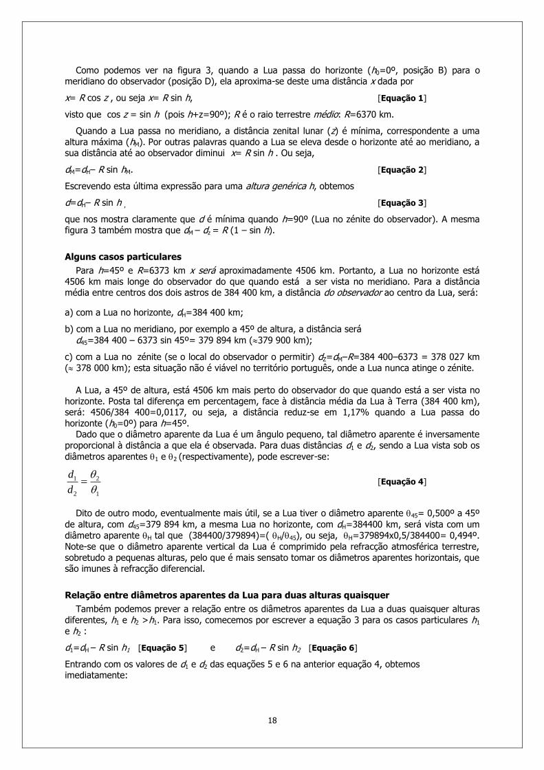
with the four ball bearings. By turning the shaft, the eyepiece tube rolls in or out. The spring pressure can be adjusted when a heavy eyepiece is used.
Figure 3- The first Crayford Focuser (left) and some of J. Wall original drawings (right).
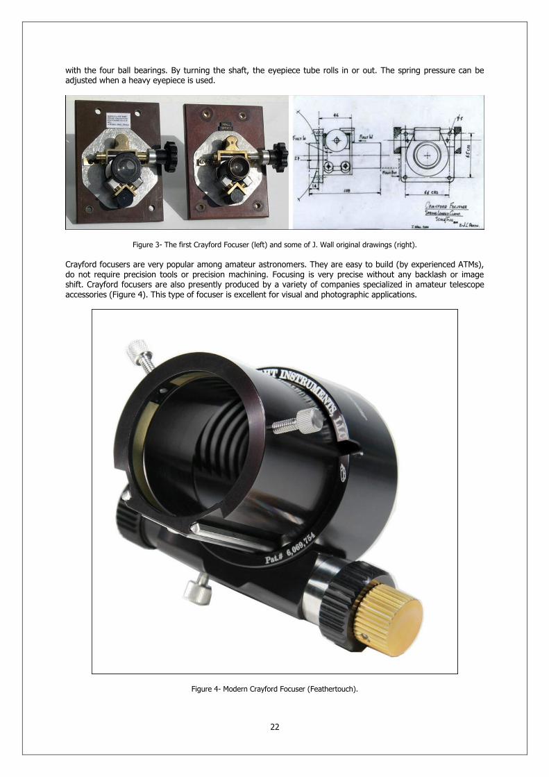
Crayford focusers are very popular among amateur astronomers. They are easy to build (by experienced ATMs), do not require precision tools or precision machining. Focusing is very precise without any backlash or image shift. Crayford focusers are also presently produced by a variety of companies specialized in amateur telescope accessories (Figure 4). This type of focuser is excellent for visual and photographic applications.
Figure 4- Modern Crayford Focuser (Feathertouch).

23
Figure 5- Modern Crayford Focusers.
24
BARNARD’S PHOTOGRAPHIC ATLAS OF SELECTED
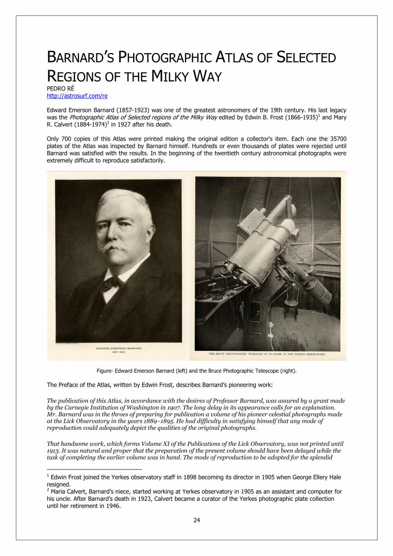
REGIONS OF THE MILKY WAY PEDRO RÉ http://astrosurf.com/re Edward Emerson Barnard (1857-1923) was one of the greatest astronomers of the 19th century. His last legacy was the Photographic Atlas of Selected regions of the Milky Way edited by Edwin B. Frost (1866-1935)1 and Mary R. Calvert (1884-1974)2 in 1927 after his death. Only 700 copies of this Atlas were printed making the original edition a collector's item. Each one the 35700 plates of the Atlas was inspected by Barnard himself. Hundreds or even thousands of plates were rejected until Barnard was satisfied with the results. In the beginning of the twentieth century astronomical photographs were extremely difficult to reproduce satisfactorily.
Figure- Edward Emerson Barnard (left) and the Bruce Photographic Telescope (right).
The Preface of the Atlas, written by Edwin Frost, describes Barnard’s pioneering work:
The publication of this Atlas, in accordance with the desires of Professor Barnard, was assured by a grant made by the Carnegie Institution of Washington in 1907. The long delay in its appearance calls for an explanation. Mr. Barnard was in the throes of preparing for publication a volume of his pioneer celestial photographs made at the Lick Observatory in the years 1889–1895. He had difficulty in satisfying himself that any mode of reproduction could adequately depict the qualities of the original photographs.
That handsome work, which forms Volume XI of the Publications of the Lick Observatory, was not printed until 1913. It was natural and proper that the preparation of the present volume should have been delayed while the task of completing the earlier volume was in hand. The mode of reproduction to be adopted for the splendid
1 Edwin Frost joined the Yerkes observatory staff in 1898 becoming its director in 1905 when George Ellery Hale resigned. 2 Maria Calvert, Barnard’s niece, started working at Yerkes observatory in 1905 as an assistant and computer for his uncle. After Barnard’s death in 1923, Calvert became a curator of the Yerkes photographic plate collection until her retirement in 1946.

25
photographs of this Atlas had not been selected at the time the original grant was made, and consequently considerable investigation and experiment were necessary in reaching a decision on this important matter. The attempts made with the photogravure and other processes did not give the assurance of uniformity that was desired, and finally the author was persuaded that actual photographic prints would be more satisfactory and hardly more expensive than any other available method of reproduction. After this decision had been reached and had been approved by the Carnegie Institution of Washington, Professor Barnard began the task of making the reproducing negatives, and then took upon himself the heavy duty of personally inspecting every print of the 35,700 needed in the issue of an edition of 700 copies. He made frequent trips to Chicago during the years 1915, 1916, and 1917 for this purpose and spared no pains to assure himself that the prints were uniform in quality and faithfully represented the originals.
The printed descriptions were written by him after a most careful study of the prints as well as of the original negatives. Professor Barnard's well–known eagerness to observe the heavens whenever the sky was clear left him little time for the remainder of the preparations of the work for publication. The reduction and publication of current observations had, with him, the right of way, and therefore it was not until late in 1922 that the first draft of the descriptions of the photographs was ready. Unfortunately, the form of publication of the whole of the Atlas had not been settled up to the time of Mr. Barnard's death, although we had had many discussions upon the subject. It had been decided that, in addition to the photographs, there should be given pen–and–ink sketches of the fields, with a system of co–ordinates by which the positions of all distinctive markings and other objects of interest could be readily noted. The form of the tables, giving further details of objects designated on the charts, had been arranged for the most part by Professor Barnard. The plan of issuing the work in two parts, so that the student of the Atlas can simultaneously have before him the photographs, its description, the key charts, and the tabular data of the objects designated, has been adopted after Mr. Barnard's death, but I believe that it would have had his approval.
In the case of the text descriptive of the photographs, the wording which Professor Barnard used has been preserved as closely as possible. Square brackets have been occasionally placed around sentences or paragraphs for which responsibility could not be assigned to the author. He left many scattered notes intended for the Introduction. These have been utilized as far as possible in carrying out the author's intention. His notes and comments were written down at times within a period of nearly a decade, during which his own views were changing and becoming more definite in certain direction. For example, when the Atlas was first planned, Professor Barnard certainly did not entertain the view that the dark markings could be anything else than vacancies in the sky. But his minute study of his many photographs gradually convinced him of the correctness of the views advanced by some other astronomers that these were dark or faintly luminous objects. The reader may easily detect the course of this changing opinion, although it could not always be brought out in its proper chronological sequence.
The increasing interest in these dark objects, as their nature has thus come to be better understood, has seemed an adequate reason for including in Part I "The Barnard Catalogue of Dark Objects," new reaching the number of 349. These will probably be designated most conveniently in the future by their numbers in this catalogue, as B 170 or B250, etc. Hundreds more of them will doubtless be located and described on these photographs or on others by future investigators.
The title assigned in 1907 to this work was “An Atlas of the Milky Way”. It was not until much later that the final choice of the areas to be included was made by Professor Barnard. That title implied that at least a large part of the Milky Way was included. This would have required from three to four times the number of photographs for which provision could be made. Accordingly, it seemed to me best, after the printing was begun, that the title should be changed to its present form, which correctly indicated that the Atlas deals with selected areas of the galaxy and that it does not attempt to include more. The diagram on page 14 of the Introduction will give a proper idea of the distribution of the plates of the galaxy.
During the years of work on the Atlas, Mr. Barnard wrote several of his most important articles on the Milky Way for appearance in the Astrophysical Journal. The following may be especially cited: "Dark Regions in the Sky Suggesting an Obscuration of Light," Astrophysical Journal, 38, 496–501, 1913; "A Great Nebulous Region Near Omicron Persei," ibid., 4 , 253–258, 1915; "Some of the Dark Markings in the Sky and What They Suggest," ibid., 43, 1–8, 1916; "On the Dark Markings of the Sky with a Catalogue of 182 Such Objects," ibid., 49, 1–23, 1919.
It was the author's expressed intention to use freely in his Introductions extracts from these papers, since as he said, they correctly express the opinions held by him at the time of the conclusion of his work on the Atlas. Limitation of space has not permitted the inclusion of many such extracts, and the reader is therefore advised to consult these papers in his use of the Atlas. Attention is called to the bibliography of Professor Barnard's principal papers in the field of celestial photography, printed on pages 15–17 of the Introduction.

26
The writer could hardly have undertaken the responsibility of completing this unfinished work upon the death of Mr. Barnard, had it not been possible for the Observatory to retain the service of Miss Calvert, who, as Mr. Barnard's person assistant, had been associated with the undertaking from its beginning. She had assisted the author in laying out a system of co–ordinates on the key charts, which she sketched under his personal supervision. She also began with him the preparation of the tables of objects noted on the charts, and later completed these, besides checking, with meticulous care, all numerical data for both parts of the Atlas. She also completed the supplementary list of dark objects begun by Mr. Barnard, determined their positions, and assigned them their numbers. I hereby express to her my appreciation of her large share in editorial duties.
I wish also to thank the officials of the Carnegie Institution of Washington for their patience in waiting for so many years for the publication of this work and for the generosity with which they have supported it. I desire also to acknowledge my appreciation of the care and attention which has been given to this publication by the University of Chicago Press and in particular by Mr. A. C. McFarland, manager of its Manufacturing Department. An acknowledgment of the fine service rendered by the photographers, Messrs. Copelin, has been given on page 13.
To all astronomers and most of the amateurs of the present generation, the remarkable observational achievements of Edward Emerson Barnard are familiar. Since this Atlas may come into the hands of some who have had little acquaintance with the development of astronomical photography it may be appropriate to say a few words regarding the career of Mr. Barnard to whom this Atlas may be considered in some sense a memorial volume.
Born at Nashville, Tennessee, on December 16, 1857, he had little opportunity for education, owing to poverty. The mystery of the starry heavens caught his attention as a lad, and almost his first purchase beyond actual necessities was a telescope with which he might penetrate farther into the illusive study of the details of the nocturnal sky. As a small boy and until young manhood, he supported himself by working at Nashville in a photographic establishment in which he learned all the details of the art, an invaluable preparation for the future application of this knowledge to the celestial field. He discovered many comets, nebulae, and other objects of interest, with his small visual telescope, and later took courses at Vanderbilt University. He made such a name for himself that he was called to be an astronomer on the staff of the Lick Observatory at its inauguration in 1888. This brilliant period of discovery and observation continued until 1895 when he came to the University of Chicago to be an astronomer at the Yerkes Observatory. Here he labored with extraordinary assiduity and with distinguished success, from the opening of the Observatory in 1897 until ill health put an end to his observations at the close of 1922.
Barnard’s Photographic Atlas of Selected Regions of the Milky Way in composed of two volumes. Part I “Photographs and Descriptions” and Part II “Charts and Tables”. Volume I contain 52 original prints produced from Barnard's original negatives, and 31 pages of Barnard's description of each plate. All Milky Way photographs were obtained with the 10" and 6.25" Bruce photographic refractors at Yerkes observatory or at Mt. Wilson observatory. The plates are glued to linen paper and have the appearance of original photographic prints. Volume 2 contains 51 charts showing objects of interest on the plates and the coordinates of the objects on the page facing the chart. Barnard wrote in the introduction of Part I:
My principal aim in presenting these photographs has been to give pictures of some of the most interesting portions of the Milky Way in such form that they may be studied for a better understanding of its general structure. They are not intended as star charts. Such photographic charts have already been made by Wolf and Palisa and by Franklin–Adams. They are probably more useful for the identification of the individual stars. But these do not give us a true picture of the parts of the sky shown, for there are structures and forms that cannot well be depicted in ordinary charts, and it has seemed to me that some of these are of the utmost importance in the study of the universe at large. These photographs may, therefore, be considered as supplementary to the regular charts in that they show the details of the clouds, nebulosities, etc. In this form, however, it is always difficult to identify the individual small stars. To overcome this difficulty charts have been prepared corresponding to each photograph and giving on the same scale a set of co–ordinates, and all the principal stars and objects of especial interest. The most useful reference stars are numbered, as are the dark objects. These charts and the tables, which give fuller data about the reference stars, will be found in Part II. It is recommended that in studying any photograph the reader should open Part II to the corresponding chart, and then he will have before him the photograph or plate, the author's text descriptive of it, the chart, with its co–ordinates, including most of the stars of the Bonner Durchmusterung, and the table supplementary to the chart.
The Milky Way has always been of the deepest interest to me. My attention was first especially attracted to its peculiar features during the period of my early comet–seeking. Indeed, there is no work in observational astronomy that gives one so great an insight into the actual heavens as that of comet–seeking. The searcher after comets sees more of the beauties of the heavens than any other observer. His telescope, though small,

27
usually has a comparatively wide field of view, and is amply powerful to show him most of the interesting parts of the sky. To him the Milky Way reveals all its wonderful structure, which is so magnificent in photographs made with the portrait lens. The observer with the more powerful telescopes, and necessarily more restricted field of view, has many things to compensate him for his small field, but he loses essentially all the wonders of the Milky Way. To me the views of the galaxy were the most fascinating part of comet–seeking, and more than paid me for the many nights of unsuccessful work. It was these views of the great structures in the Sagittarius region of the Milky Way that inspired me with the desire to photograph these extraordinary features, and one of the greatest pleasures of my life was when this was successfully done at the Lick Observatory in the summer of 1889.
The contents of the second volume of the Atlas are described in the Introduction of Part II:
This second part of the Atlas has been provided to aid in the convenient use and study of the photographs contained in Part I, for reasons which were stated in notes by Professor Barnard as follows:
When comparing astronomical photographs made with long exposures with star charts I have frequently had much trouble, through the want of an approximate position, in identifying stars and other objects on the photographs. Also, very often the colors of the stars so change their relative intensities that they are not easily recognized on the chart. The photographs in the present work are intended as pictures of the sky and it would have been impossible to mark co–ordinates on them without spoiling their pictorial value. It was therefore decided to make a map, with co–ordinates, corresponding to each photograph and on the same scale. Though this has required much work, the charts assist greatly in the approximate location of any object shown on the photographs. They have been of great service to me in studying the photographs and I believe will be a welcome addition to the Atlas.
The photographs are not all enlarged in the same proportion, and therefore are not uniform in scale. All of the fainter stars shown on the Durchmusterung charts were not put on the diagrams, but it is believed enough of them are given to permit a ready identification of objects in any part of a photograph. Found stars on each photograph, located near the corners, were identified and used for determining its scale and for locating the system of co–ordinate lines. The epoch 1875.0 was adopted and is used throughout this work. A high degree of accuracy is not claimed for these charts, but they are sufficiently precise to locate and object closely enough for identification in a catalogue.
All of the dark objects listed by Professor Barnard which fall within the limits of the various plates have been roughly outlined on the charts so as to aid in their identification. Some of these are so indefinite that no mere outline can represent them. In general, a dotted line is used to indicate outlines that are vague, while a solid line implies more definiteness. Each of these dark objects is designated by the letter B followed by its number in Professor Barnard's list printed in the Astrophysical Journal or in his supplementary list, both of which are given in Part I.
Nebulosity shown on the photographs is indicated on the charts by parallel lines.
Numbers have been given on the diagrams to such stars and objects as were mentioned in the text accompanying the photographs in Par I, and to such others as might assist in the easy location of details in any part of the plate. The numbers were carried consecutively though the whole series of diagrams but are not always repeated when they occur on several charts.
These numbered stars and objects are listed in the tables that face the diagrams, with their positions for 1875.0 and the other data which were thought to be useful.
The second column contains the number of the star or other object in the Bonner Durchmusterung(B.D.), the Cordoba Durchmusterung (C.D.), or the New General Catalogue (N.G.C.) of the late J. E. L. Dreyer based on the observations of the Herschels and later astronomers. Numbers taken from Dreyer's extensions of the N.G.C., published in the first and second index catalogues, are designated as N.G.C. I and II. No attempt has been made to include all the objects of the N.G.C. that occur within the limits of the photographs, and only the more conspicuous of them are listed. Nebulous stars are generally noted.
The magnitude in the third column is the visual estimate for the star as given in the Bonner or the Cordoba Durchmusterung. Clusters and nebulae are also indicated in the column. The right ascensions and declinations as given are, in general, not the Durchmusterung positions but have been taken from the catalogues of the Astronomische Gesellschaft and have been rounded off to the tenth of a second of time in a and the tenth of a minute of arc in d.

28
The data for the photometric (visual) and photographic magnitudes and for the type of spectrum have been taken from the Henry Draper Catalogue, Annals of the Harvard College Observatory, 91–99. For the benefit of those not technically acquainted with these matters it may be stated that types O, B, and A include the blue and bluish–white stars; F and G, the yellow stars; while K stars have an orange tinge and those of type M are distinctly red.
The column of "Remarks" gives the Greek letter and Flamsteed number of such stars as may have them, and Messier's numbers. The N.G.C. number is printed here when the object has a Durchmusterung number already entered in the second column. Nebulous stars are also indicated in this column.
The approximate positions of the dark objects shown on the various photographs are given below the table for each chart.
It is assumed that the user of the Atlas making a careful study of a particular photograph will open both parts to the corresponding place. He will then have at once before him, without the necessity of turning pages, the photograph, faced by the author's description of its features, while the chart will give the approximate co–ordinates in right ascension and declination and the designation of the stars and other objects, for which full details are given in the table opposite to it. This plan of publishing the Atlas in two parts had not been decided upon before Professor Barnard's death, but it is believed that it would have met his approval. Most of the charts had been prepared in a preliminary way by Miss Calvert under Professor Barnard's supervision. She later sketched in the dark objects and inserted their numbers and those of the reference stars, after completing the computation s and checking necessary for the tables.
In this introduction, Barnard makes a detailed description of the Bruce photographic telescope:
My experience at the Lick Observatory with the Willard portrait lens impressed me with the importance of that form of instrument for the picturing of large regions of the heavens. That lens, which was purchased at second hand from a photographer in San Francisco, was made for, and originally used in, taking portraits — from which fact its name has come. These large short–focus lenses were necessary in the days of wet–plate photography to gather a great quantity of light and to give a brilliant image to lessen as much as possible the time of sitting. But when the rapid dry plates came into use these lenses were no longer needed, and much smaller, more convenient, and less expensive lenses took their place. The great light–gathering power for which they were so valuable in the wet–plate days makes them especially suitable for the photography of the fainter celestial bodies. They were made on the Petzval systems and consisted of two sets of lenses, from which fact they are also called "doublets." In this paper I shall refer to them namely as "portrait lenses," as that name appeals more directly to me. The main advantage of the portrait lens lies in its grasp of wide areas of the sky and its rapidity of action – this last result being due to its relatively short focus. The wide field makes it especially suitable for the delineation of the large structural details of the Milky Way; for the discovery of the great nebulous regions of the sky; for the investigation of meteors and the determination of their distances; and especially for the faithful portrayal of the rapid changes that take place in the forms and structures of comets' tails. The portrait combination is not intended in any way to compete with the astrographic telescopes, or with any of the larger photographic refractors or reflectors. It must be considered as supplemental to these, because their limited field confines them to small areas of the sky. There is a great and valuable work for these larger telescopes, however, in the accurate registration of the places of the stars, for parallax, and, in the reflector, for depicting the features of the well–known nebulae, etc. There is, I think, however, a question as to the most advantageous size for a portrait lens, and I have believed that the best results can be obtained with an instrument of moderate size; or, in other words, I believe that a portrait lens can be made too large to give the very best results, just as it can be too small. It is also true that both large and small portrait lenses are individually valuable. There is a kind of supplementary relationship between them. The small one will do work that the large one cannot do' and the reverse of this is equally true; for though the small one is quicker for a surface – such, for instance, as the cloud forms of the Milky Way present to it – the larger one, mainly on account of its greater scale, will show details that are beyond the reach of the smaller one. Another important fact is that as the size of the lens increases, the width of the field rapidly diminishes, and width of field is one of the essential features of the value of the portrait lens (…)
As a matter of experience, it has seemed to me that a lens of the portrait combination about 10 inches in diameter would best serve the purpose of the investigations that have just been outlined.
For several years I had tried to interest someone in the purchase of such a lens, but without success. Finally, I brought the matter before Miss Catherine W. Bruce, who had done so much already for the advancement of astronomy. In the summer of 1897 Miss Bruce placed in my hands, as a gift to the University of Chicago, the sum of $7,000 for the purchase of such an instrument and for the erection of a small observatory to contain it.
The instrument consists of a 5–inch guiding telescope and two photographic doublets of 10 and 6 ¼ inches aperture, rigidly bound together on the same mounting. An unusual delay was produced by my anxiety to get
29
the best possible lens for the purpose. The long exposures demanded in the work of an instrument of this kind require an unusual form of mounting to give an uninterrupted exposure. The mounting of the Willard lens was an ordinary equatorial and was not made especially for it. It did not permit an exposure to be carried through the meridian, except in southern declinations. This was a great drawback since in a long exposure it was necessary to give all the time on one side instead of dividing it up to the best advantage on each side o the meridian (…)
In the meantime, Mr. Brashear, with characteristic faith in his skill, ordered the glass and made a 10–inch doublet on his own responsibility. This lens gave exquisite definition over a field some 7° in width and could by averaging be made to cover at least 9° of fairly good definition. Though this did not come up to the width of field originally proposed, it was finally accepted, as it seemed the best that could be obtained.
The glass disks were made by Mantois, of Paris, and delivered to Brashear in May of 1899, and the lenses were completed in September, 1900. The following information about the 10–inch lens was supplied me by Dr. Brashear:
The general construction is that which was first found by Petzval several years ago, and has proven itself quite the best where great angular aperture and sharp definition is imperative. The curves have been somewhat modified from our experience in the construction of other lenses – particularly of those made for Dr. Max Wolf, of Heidelberg, Germany. It departs, however, from the ordinary practice of opticians in being corrected for short wavelengths of light. This would be quite objectless in a camera which is to be used for portraits, but it is not without moment in astronomical photography.
The materials employed were specially chosen for their transparency – the flint being very light and the crown very white. The focal lengths of the front and rear combinations are in a ratio of about 7 to 12, while the focal length of the system is very nearly five times the aperture. The focal length you may find very slightly modified; indeed, it is our custom to balance the inevitable zonal differences of magnification to all constructors of astronomical objectives. The focus of the 10–inch, determined form the photographs, is 50.3 inches (127.8 cm), and the scale is therefore 1 inch = 1°14 or 1° = 0.88 inch. The ratio, a/f = 1/5.03, I believe to be the best for the purpose. The accumulation of interest had by this time permitted the purchase of a 6 ½–inch Voigtlander lens of 30.9 inches (78.5 cm) focus, which had been in commercial use.
As indicated, the telescope is really triple in character, there being three tubes bound rigidly together on the same mounting – the 5–inch visual telescope for guiding, and the 10–inch and 6 1/4 –inch photographic doublets. For each of the photographic lenses there is an inner tube, with focusing scale, which can be racked back and forth for the adjustment of focus. There is considerable change of focus in the 10–inch lens between winter and summer. The change in the focus of the 6–inch is small, however, and requires very little correction.
The plate–holder for the ten–inch carries a plate 12 inches square, while the one for the 6 ¼ –inch carries a plate 8×10 inches.
In the matter of a guiding telescope the limited means would not permit of anything larger than 5 inches, which is sufficiently powerful for ordinary purposes, though for the photography of comets a larger one would have been desirable. The guiding telescope I used with the Willard lens at Mount Hamilton was only 1 ¾ inches in diameter. Of course the question of a double–slide plate holder was considered; but in a small telescope like this the tubes are so rigidly bound together that such a device is not necessary to insure faithful guiding. Furthermore, for work of this kind the double–slide plate–holder would be seriously objectionable.
A high–power eyepiece is used on the 5–inch for guiding in conjunction with a right–angled prism. This is more convenient than direct vision, especially when photographing at high altitudes. The eyepiece has an adjustable motion to the extent of 2° in any direction, thus insuring the finding of a suitable guiding star. This is also valuable in photographing a comet, as it permits the displacement of the comet's head to one side of the center of the plate, thus securing a better representation of the tail.
Two spider–line cross–wires in the eyepiece are used for guiding. They are illuminated by a small electric lamp by the aid of two small reflecting surfaces which throw the light perpendicularly on the wires. The intensity of the illumination is readily regulated. By this means almost the smallest star visible in the 5–inch can be used for guiding purposes (…)
The pier really consists of two parts. Just above the clock room is separates into two pieces which are bolted together on the inside of the pier, and hence no break appears in the continuity of the pier.
For change of latitude, it is only necessary to insert a wedge–shaped section between these two parts of such an angle that it will produce the required change of latitude. This ordinarily would necessitate only a slight change in the length of the driving–rod which is adjustable. No other means of adjustment seemed feasible.

30
As it was possible that the instrument might sometime go to the southern hemisphere, Messers. Warner and Swasey were asked to insert some sort of gearing that would readily permit of a reversal of the motion of the clock. The device they introduced is extremely simple and efficient. In a couple of minutes' time the motion can be changed from west to east. At the point where the driving–rod joins on to the worm–screw for driving the worm–wheel carrying the telescope, the small gear–wheel which makes the connection can be reversed and placed on the other side of the gear–wheel at the end of the driving–rod; this will reverse the direction of the motion of the worm–wheel and hence of the telescope.
The telescope is supplied with fine and coarse right–ascension and declination circles; the fine circles are divided on silver and are read by verniers.
The slow motions for guising are brought down conveniently to the plate–end of the instrument.
The pier is very heavy, weighing some 1,200 or 1,300 lbs. (550–600 kilos). This great weight is necessary to support the overhanging mass of the telescopes and the top of the pier.
The driving–clock is of Warner and Swasey's regular conical pendulum pattern, which by all means seems to be the best form of driving–clock. It is a beautiful piece of mechanism and performs satisfactorily, though we intend to introduce an electric control for work with it hereafter.
The instrument was finally finished and placed in position in its observatory in April 1904(…)
The 10–inch and the 6 ¼–inch, therefore, mounted together, give a very desirable variety in respect to scale, at the same time that the 6–inch is sufficiently powerful to be an almost perfect verification of anything the 10–inch may show.
One minor source of trouble with both these lenses, but worse in the case of the 10–inch, is that the commercial plates that are used are never flat. In one sense this is a distinct advantage as the emulsion is placed on the concave side of the plates; this helps to flatten the field. But the curvature is not always the same, for some plates are curved more than others. This is equivalent to a frequent change of focus with the larger lens. Once in a very long while the emulsion is put on the convex side of the plate. This puts the sensitive surface too much inside the focus and the result is a spoiled picture.
The Bruce Observatory is a wooden building of size, 15×33 feet, with the greater length lying east and west. The dome, which is central, is 15 feet in diameter and revolves on 8–inch roller–bearing iron wheels.
The large field of the Bruce telescope made a wide opening in the dome a necessity. It was therefore made 4 feet wide, which seems ample for all purposes. The telescope rests on a brick pier, and the observing room is reached by a small stairway against the inner south wall of the building.
The altitude of the telescope above sea–level is about 1,040 feet (317 meters). Its latitude is 42°34' (...)
Through the interest and courtesy of Professor George E. Hale and the generosity of Mr. John D. Hooker, of Los Angeles, I spent the spring and summer of 1905 in photographic work at the Solar Observatory of the Carnegie Institution on Mount Wilson, California. Mr. Hooker's generous grant made it possible to transport the Bruce telescope to Mount Wilson, where it was installed from February until September, 1905, in a temporary wooden structure, from which the roof could be slid off, giving an unbroken view of the sky. The altitude of the station was about 5,900 feet (1,800 meters), above the sea, and its latitude 34°13'.
The main object of this expedition to Mount Wilson was to secure the best possible photographs of the Milky Way as far south as the latitude would permit. But little time was available for independent investigations into other parts of the sky, though the conditions for such work were often superb. During this period 154 plates were obtained with the 10–inch Brashbear doublet, and 151 with the 6 ¼–inch Voigtlander doublet, the exposures being simultaneous, almost without exception. The original negatives of 40 of the 50 photographs in this volume were made during the time at Mount Wilson.
During many of the exposures at Mount Wilson two additional cameras were used, being attached to the mounting of the instrument, as shown in the picture. These were a Clark lens of 3.4 inches aperture and 20 inches focus and a so–called "lantern" lens of aperture 1.6 inches and focal length of 6.3 inches. With the Clark lens about 110 negatives were obtained and about 90 with the stereopticon lens.

31
Sources:
Barnard, E.E. (1905). The Bruce photographic telescope of the Yerkes Observatory. Astrophysical Journal, 21: 35-48
Barnard, E.E. (1913). Photographs of the Milky Way and of Comets. Publications of Lick Observatory, vol. 11.
Banard, E.E. (1927). A Photographic Atlas of Selected Regions of the Milky Way. Carnegie Institution of Washington. Publication No. 247 (Part I and Part II).
A Photographic Atlas of Selected Regions of the Milky Way (Web Page). http://www.library.gatech.edu/barnard/
Sheehan, W. (1995). The Immortal Fire Within: The Life and Work of Edward Emerson Barnard. Cambridge University Press, ISBN 0 521 44489 6.
Figure 2- Bruce photographic telescope in a temporary roll-off-roof observatory on Mt. Wilson (1905) (left). Rho Ophiuchi region, exposure 4h30m, April 5, 1905 (right).
Figure 3- Plate coordinates (Photographic Atlas of Selected Regions of the Milky Way).
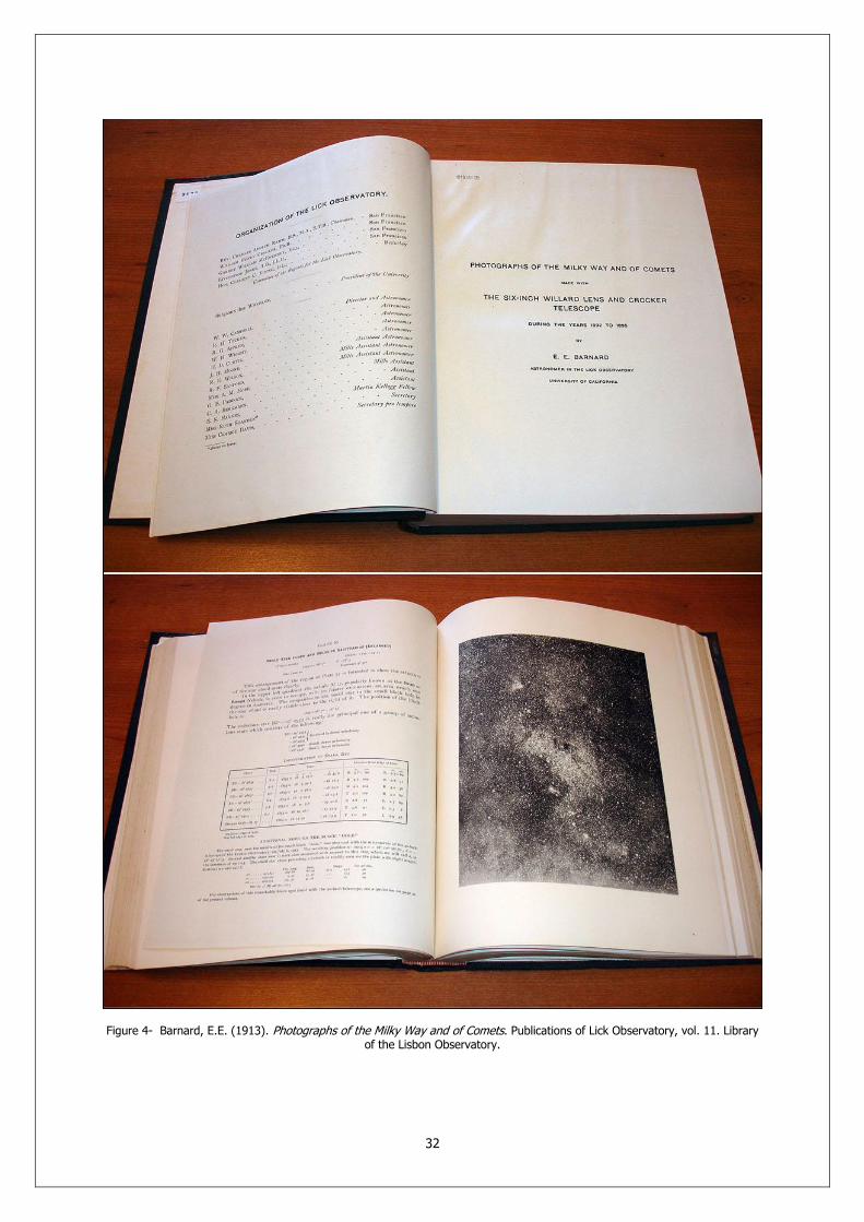
32
Figure 4- Barnard, E.E. (1913). Photographs of the Milky Way and of Comets. Publications of Lick Observatory, vol. 11. Library of the Lisbon Observatory.

33
Figure 5- Barnard, E.E. (1927). Photographic Atlas of Selected Regions of the Milky Way. Author’s personal copy.

34
WILLIAM LASSELL’S (1799-1880) TELESCOPES
AND THE DISCOVERY OF TRITON PEDRO RÉ http://astrosurf.com/re William Lassell (1799-1880) (Figure 1) was born in Bolton in 1799. His family business was associated with clock and watch making. Lassell became an amateur astronomer and a telescope maker at an early age. With only 21 years he built two reflecting telescopes of 7-inch aperture, a Newtonian and a Gregorian. Soon after, a private observatory was built, housing a 9-inch Newtonian equatorial mounted telescope. Lassell married a widow of a wealthy Liverpool brewer gaining at the same time financial independence. He founded his own brewery in 1825 and from it secured the fortune that permitted him to devote his entire time to building and using large telescopes of his own making. Lassell was well known for his exceptional mechanical skills. His mountings and speculum-mirrors were among the best during the early nineteen century. Lassell is also considered by some authors as the creator of the first modern big reflecting telescopes.
Figure 1- William Lassell and the 9-inch reflector.
His first mirrors were cast around 1820. In 1839 he described his 9-inch equatorial reflector to the Royal Astronomical Society. It was considered at the time as a big step forward. The tube and mount were built in cast iron. The speculum mirror had a focal length of 112 inches. The telescope was mounted in an iron box that was bolted upon an iron cone (Figure 1). Ball-bearings were used in all the moving parts of the mount. Lassell claimed that the motions were perfect and that the whole telescope could be easily moved with the pressure of a finger. Lassell used this telescope mainly for the observation of the planets. In 1843 he decided to build a 24-inch reflector. This instrument was an enlarged version of the 9-inch (Lassell never published a detailed drawing if this instrument). A steam-driven machine was built for grinding and
polishing the 24-inch speculum mirror. The instrument was completed in 1845 (Figure 2). The original speculum mirror weighting 168 kg was made of a special alloy of copper and tin (with small quantities of arsenic). The f/10 mirror was installed in a 6 m long tube made of thick sheet iron. The tube was riveted internally and could be rotated for the comfort of the observer (Newtonian focus). When the tube was on the vertical position the height of the whole instrument was close to 9 m. The secondary mirror was also made of speculum. Lassell sometimes used a prism instead of the secondary mirror that was heated (to prevent due) by placing a hot iron cube wrapped in felt in a special holder close to it.

35
The overall weight of the telescope was over 2 tons. The equatorial mount rested in two stone piers that weighted 6 tons. This innovative telescope was the first big reflector mounted on an equatorial mount. There was no clock-drive, the telescope was driven by means of a winch handle operated by an assistant. This telescope was completely restored in 1996. The Lassell telescope project started in 1995 and the fully restored telescope was presented to the public by the Liverpool Museum, on October 10, 1996.
Figure 2- Model and artist’s impression of the 24-inch Lassell reflector telescope.
Before building the 24-inch, Lassell visited Parsonstown were he inspected the erection of the Leviathan and Lord Rosse’s workshops and instruments. Lassell invented a curved-stroke machine to grind and polish his speculum mirrors. This machine was different from the straight-stroke machines devised by Lord Rosse. He also cooperated with James Nasmyth (1808-1890) who was a gifted mechanical engineer and amateur astronomer. Nasmyth extensive foundry experience was invaluable to Lassell and his telescope making projects. Lassel discovered Triton, the brightest satellite of Neptune, with the 24-inch reflector. The Planet Neptune itself was founded on September 23, 1846. The Triton discovery was made soon after, on October 10, 1846. The first observations made by Lassell on October 2 and 3, enabled him to see a clear disk. He was also convinced that the planet had a ring similar to what can be observed in Saturn. Two years later he discovered Hyperion, the eight satellite of Saturn. In 1852, the 24-inch was moved to the isle of Malta in the Mediterranean. There, during the winter season, and under clear skies, Lassell was able to observe clearly four satellites of Uranus. At this point, Lassell undertook the building of a 48-inch reflector. The telescope was first erected in Liverpool on the grounds of his villa. The 48-inch f/9.4 speculum mirror had a 11.1 m open tube made of flat iron bars. It was mounted as a Newtonian. The author described this instrument in considerable detail (Memoirs of the Royal Astronomical Society, 36, 1867):
There is no roof or covering over the telescope, but the observers are protected by being placed in one or other of the storeys of a tower, which affords a means of getting conveniently at the eyepiece, which, when the telescope points to the zenith, is about 39 feet from the ground. A staircase within the tower leads to the different storeys, which are about 4 feet and 6 inches square, and afford abundant room for papers, micrometers, eyepieces, lamps, and other small apparatus required; beside furnishing to the observer a most grateful shelter from the dew, and occasionally from the inclement wind. During observation, however the size of the storey in use becomes practically much larger, by the opening of the folding doors and letting down the platform, as shown in the engraving (Figure 3); the available space being then about 6 feet 9 by 4 feet and 6 inches. The tower is carried round on a circular railway, and has besides, a revolution on its axis, and a radial motion to and from the telescope: so that at most altitudes and hour-angles the eyepiece is easily accessible. It has been usual, however, for the most obvious reasons, to observe within three hours of the meridian, east or west.

36
Figure 3- William Lassell and the 48-inch reflector (Memoirs of the Royal Astronomical Society, 36, 1867).
The 48-inch mount had no driving clock. It was moved through a gear train with the help of an assistant that turned the crank once each second in synchronism with a clock. A star or planet could, with this primitive arrangement, be kept within the field of view for several hours (the moving parts of the whole telescope weighted more than eight tons). With this telescope, Lassell observed mainly nebulae. At the time, it was the largest telescope in England. Several drawings were published: Dumbell nebula in Vulpecula (M27); Ring nebula in Lyra (M57); Crab nebula in Taurus (M1) and M88 in Coma Berenices (Memoirs of the Royal Astronomical Society, 36, 1867). Lassell regarded these drawings as accurate representations of these objects. In the case of M27 Lassell mentioned that the nebula could not be resolved into stars and that the stars in the field were not connected to the nebula “the sky around is quite as full of stars as the space occupied by the nebula” (Figure 4).
In 1861 the 48-inch was moved to Malta. During a period of four years a huge number of observations were performed: measurements of faint planet satellites; bright nebula; planetary surfaces (…)
A number of nebulae were recognized as spirals with the 48-inch. A catalogue of previously unknown nebulae was compiled under the clear skies of Malta. Most of these observations were done by Lassell’s assistant Albert Marth (1828-1897). Marth was a hardworking German astronomer that never received adequate recognition for his important contributions to astronomy. Lassell returned to England in 1865 but 48-inch was never re-erected. It was sold as scrap metal shortly before his death in 1880. He wrote “(…) when witnessing the breaking up of the speculum I was not without a pang or two on hearing the heavy blows of sledge-hammers necessary to overcome the firmness of the alloy”.

37
Figure 4- Drawings of several nebulae made by William Lassell with the 48-inch telescope in Malta: upper left M1; below M88; right M27 (Memoirs of the Royal Astronomical Society, 36, 1867).
Sources:
Danjon, A. & A. Couder (1935). Lunettes et Télescopes. Livrarie Scientifique et Technique, Paris. Glass, I.S. (1997). Victorian Telescope Makers: The Lives & Letters of Thomas & Howard Grubb.
Institute of Physics Publishing, London King, H.C. (1955). The History of the Telescope. Dover Publications, Inc. New York.

38
JAMES NASMYTH’S (1808-1890) TELESCOPES PEDRO RÉ http://www.astrosurf.com/re James Hall Nasmyth (1808-1890) was a master engineer with his own workshop for casting specula in Patricroft (near Manchester, U.K.). As a young man, Nasmyth spent a considerable amount of time in foundries and chemical laboratories. He became well known as a maker of working models of steam engines. He is also known as the investor of the steam hammer. In 1827, at the age of 19, Nasmyth built a road steam-carriage that can be considered as a precursor to the automobile. Nasmyth many years later refers in his autobiography:
About the year 1827, when I was nineteen years old, the subject of steam carriages to run upon common roads occupied considerable attention. Several engineers and mechanical schemers had tried their hands, but as yet no substantial results had come of their attempts to solve the problem. Like others, I tried my hand. Having made a small working model of a steam-carriage, I exhibited it before the members of the Scottish Society of Arts. The performance of this active little machine was so gratifying to the Society that they requested me to construct one of such power as to enable four or six persons to be conveyed along the ordinary roads. The members of the Society, in their individual capacity, subscribed 60, which they placed in my hands as the means for carrying out their project.
I accordingly set to work at once. I had the heavy parts of the engine and carriage done at Anderson's foundry at Leith. There was in Anderson's employment a most able general mechanic named Robert Maclaughlan, who had served his time at Carmichaels' of Dundee. Anderson possessed some excellent tools, which enabled me to proceed rapidly with the work. Besides, he was most friendly, and took much delight in being concerned in my enterprise. This "big job" was executed in about four months. The steam-carriage was completed and exhibited before the members of the Society of Arts. Many successful trials were made with it on the Queensferry Road, near Edinburgh. The runs were generally of four or five miles, with a load of eight passengers sitting on benches about three feet from the ground.
The experiments were continued for nearly three months, to the great satisfaction of the members. I may mention that in my steam-carriage I employed the waste steam to create a blast or draught by discharging it into the short chimney of the boiler at its lowest part, and found it most effective. I was not at that time aware that George Stephenson and others had adopted the same method; but it was afterwards gratifying to me to find that I had been correct as regards the important uses of the steam blast in the chimney. In fact, it is to this use of the waste steam that we owe the practical success of the locomotive-engine as a tractive power on railways, especially at high speeds3.
Nasmyth started his own factory at Patricroft after working for three years with the famous engineer Henry Maudslay (1771-1831). Machinery of all kinds was manufactured such as steam engines and especially improved machine tools. His many inventions (which included steam hammers, pile drivers, hydraulic pumps and flexible
shafting for driving small drills…) made him a rich man. Nasmyth retired at an early age of 48 devoting all his time to astronomy and the construction of telescopes.
His first telescope was built in 1827 (a 6-inch reflector with a speculum mirror). He recalls in his autobiography:
I cannot find words to express the thoughts which the impressive grandeur of the Stars, seen in the silence of the night, suggested to me; especially when I directed my Telescope, even at random, on any portion of the clear sky, and considered that each Star of the multitude it revealed to me, was a Sun! The centre of a system! Myriads of such stars, invisible to the unassisted eye, were rendered perfectly distinct by the aid of the telescope. The magnificence of the sight was vastly increased when the telescope was directed to any portion of the Milky Way. It revealed such countless multitudes of stars that I had only to sit before the eyepiece, and behold the endless procession of these glorious objects pass before me. The motion of the earth assisted in changing this scene of inexpressible magnificence, which reached its climax when some object such as the "Cluster in Hercules" came into sight. The component stars are so crowded together there as to give the cluster the appearance of a gray spot; but when examined with a telescope of large aperture, it becomes resolved into such myriads of stars as to defy all attempts to count them. (…) I had already a slight acquaintance with Astronomy. My father had implanted in me the first germs. He was a great admirer of that sublimest of sciences. I had obtained a sufficient amount of technical knowledge to construct in 1827 a small but very effective reflecting telescope of six inches
3 Nasmyth, J. (1897). James Nasmyth: Engineer: An Autobiography. Edited by Samuel Smiles. John Murray, London.

39
diameter. Three years later I initiated Mr. Maudslay into the art and mystery of making a reflecting telescope. I then made a speculum of ten inches diameter, and but for the unhappy circumstance of his death in 1831, it would have been mounted in his proposed observatory at Norwood. After I had settled down at Fireside, Patricroft, I desired to possess a telescope of considerable power in order to enjoy the tranquil pleasure of surveying the heavens in their impressive grandeur at night4.
Nasmyth was planning to build a 24-inch telescope for Maudslay’s private observatory when the latter died in 1831. Telescope making was resumed at Patricoft with great success. His close collaboration with William Lassel (1799-1880) also began in 1840, a collaboration that lasted for forty years.
As I had all the means and appliances for casting specula at the factory, I soon had the felicity of embodying all my former self-acquired skill in this fine art by producing a very perfect casting of a ten-inch diameter speculum. The alloy consisted of fifteen parts of pure tin and thirty-two parts of pure copper, with one part of arsenic. It was cast with perfect soundness, and was ground and polished by a machine which I contrived for the purpose. The speculum was so brilliant that when my friend William Lassell saw it, he said "it made his mouth water." It was about this time (1840) that I had the great happiness of becoming acquainted with Mr. Lassell. Mr. Lassell was a man of superb powers. Like many others who have done so much for astronomy, he started as an amateur. He was first apprenticed to a merchant at Liverpool. He then began business as a brewer. Eventually he devoted himself to astronomy and astronomical mechanics. When in his twenty-first year he began constructing reflecting telescopes for himself. He proceeded to make a Newtonian of nine inches aperture, which he erected in an observatory at his residence near Liverpool, happily named "Starfield." With this instrument he worked diligently, and detected the sixth star in the trapezium of Orion. In 1844 he conceived the bold idea of constructing a reflector of two feet aperture, and twenty feet focal length, to be mounted equatorially. Sir John Herschel, in mentioning Mr. Lassell's work, did me the honour of saying "that in Mr. Nasmyth he was fortunate to find a mechanist capable of executing in the highest perfection all his conceptions, and prepared by his own love of astronomy and practical acquaintance with astronomical observations, and with the construction of specula, to give them their full effect." With this fine instrument Mr. Lassell discovered the satellite of Neptune. He also discovered the eighth satellite of Saturn, of extreme minuteness, as well as two additional satellites of Uranus. But perhaps his best work was done at Malta with a much larger telescope, four feet in aperture, and thirty-seven feet focus, erected there in 1861. He remained at Malta for three years, and published a catalogue of 600 new nebulae, which will be found in the Memoirs of the Royal Astronomical Society. One of his curious sayings was, "I have had a great deal to do with opticians, some of them—like Cooke of York—are really opticians; but the greater number of them are merely shop opticians!" and profiting by his devotion to astronomical pursuits and his profound knowledge of the subject. He had acquired much technical skill in the construction of reflecting telescopes, and the companionship between us was thus rendered very agreeable. There was an intimate exchange of opinions on the subject, and my friendship with him continued during forty successive years. I was perhaps a little ahead of him in certain respects. I had more practical knowledge of casting, for I had begun when a boy in my bedroom at Edinburgh. In course of time I contrived many practical "dodges" (if I may use such a word), and could nimbly vault over difficulties of a special kind which had hitherto formed a barrier in the way of amateur speculum makers when fighting their way to a home-made telescope. I may mention that I know of no mechanical pursuit in connection with science, that offers such an opportunity for practicing the technical arts, as that of constructing from first to last a complete Newtonian or Gregorian Reflecting Telescope. Such an enterprise brings before the amateur a succession of the most interesting and instructive mechanical arts, and obliges the experimenter to exercise the faculty of delicate manipulation. If I were asked what course of practice was the best to instil a true taste for refined mechanical work, I should say, set to and make for yourself from first to last a reflecting telescope with a metallic speculum. Buy nothing but the raw material, and work your way to the possession of a telescope by means of your own individual labour and skill. If you do your work with the care, intelligence, and patience that is necessary, you will find a glorious reward in the enhanced enjoyment of a night with the heavens—all the result of your own ingenuity and handiwork. It will prove a source of abundant pleasure and of infinite enjoyment for the rest of your life5.
Nasmyth started building a 20-inch of his own design soon after (Figure 1).
My ambition expanded. I now resolved to construct a reflecting telescope of considerably greater power than that which I possessed. I made one of twenty inches diameter, and mounted it on a very simple plan, thus removing many of the inconveniences and even personal risks that attend the use of such instruments. It had been necessary to mount steps or ladders to get at the eyepiece, especially when the objects to be observed were at a high elevation above the horizon. I now prepared to do some special work with this instrument. In 1842 I began my systematic researches upon the Moon. I carefully and minutely scrutinized the marvelous details of its
4 Nasmyth, J. (1897). James Nasmyth: Engineer: An Autobiography. Samuel Smiles Ed. John Murray, London. 5 Nasmyth, J. (1897). James Nasmyth: Engineer: An Autobiography. Samuel Smiles Ed. John Murray, London.

40
surface, a pursuit which I continued for many years, and still continue with ardour until this day. My method was as follows:
I availed myself of every favorable opportunity for carrying on the investigation. I made careful drawings with black and white chalk on large sheets of grey-tinted paper, of such selected portions of the Moon as embodied the most characteristic and instructive features of her wonderful surface. I was thus enabled to graphically represent the details with due fidelity as to form, as well as with regard to the striking effect of the original in its masses of light and shade. I thus educated my eye for the special object by systematic and careful observation, and at the same time practiced my hand in no less careful delineation of all that was so distinctly presented to me by the telescope—at the side of which my sheet of paper was handily fixed. I became in a manner familiar with the vast variety of those distinct manifestations of volcanic action, which at some inconceivably remote period had produced these wonderful features and details of the moon's surface. So far as could be observed, there was an entire absence of any agency of change, so that their formation must have remained absolutely intact since the original cosmical heat of the moon had passed rapidly into space. The surface, with all its wondrous details, presents the same aspect as it did probably millions of ages ago.
This consideration vastly enhances the deep interest with which we look upon the moon and its volcanic details. It is totally without an atmosphere, or of a vapour envelope, such as the earth possesses, and which must have contributed to the conservation of the cosmical heat of the latter orb. The moon is of relatively small mass, and is consequently inferior in heat-retaining power. It must thus have parted with its original stock of cosmical heat with such rapidity as to bring about the final termination of those surface changes which give it so peculiar an aspect. In the case of the earth the internal heat still continues in operation, though in a vastly reduced degree of activity. Again in the case of the moon, the total absence of water as well as atmosphere has removed from it all those activities which, in the earth, have acted so powerfully in effecting changes of its surfaces as well as in the distribution of its materials. Hence the appearance of the wonderful details of the moon's surface presents us with objects of inconceivably remote antiquity6.
Figure 1- Nasmyth’s 20-inch Cassegrain-Newton (ca. 1845) (left). Diagram of a Nasmyth stationary-eyepiece telescope (right).
6 Nasmyth, J. (1897). James Nasmyth: Engineer: An Autobiography. Samuel Smiles Ed. John Murray, London.

41
A systematic lunar observation program started in 1842. Nasmyth was convinced that all Moon craters were produced by volcanic activity. These innovative ideas were described in the book The Moon Considered as a Planet, a World, and a Satellite published in 1874 by James Nasmyth and James Carpenter (1840-1899). Several photographs of plaster models of lunar features were included based on drawings and not on precise measurements of the lunar surface features. Nasmyth made also many observations of the fine structure of the Sun surface. He interpreted the features he saw as similar to willow leaf shaped objects (Figure 2):
I had been busily occupied for some time in making careful investigations into the dark spots upon the Sun's surface. These spots are of extraordinary dimensions, sometimes more than 10,000 miles in diameter. Our world might be dropped into them. I observed that the spots were sometimes bridged over by a streak of light, formed of willow-leaf-shaped objects. They were apparently possessed of voluntary motion, and moved from one side of the spot to the other. These flakes were evidently the immediate sources of the solar light and heat. I wrote a paper on the subject, which I sent to the Literary and Philosophical Society of Manchester … Memoirs of the Literary and Philosophical Society of Manchester, 3d series, vol. I, p. 407. My first discovery of the "Willow-leaf" objects on the Sun's surface was made in June 1860. I afterwards obtained several glimpses of them from time to time. But the occasions are very rare when the bright sun can be seen in a tranquil atmosphere free from vibrations, and when the delicate objects on its surface can be clearly defined. It was not until the 5th of June 1864 that I obtained the finest sight of the Sun's spots and the Willow-leaf objects; it was then that I made a careful drawing of them, from which the annexed faithful engraving has been produced. Indeed I never had a better sight of this extraordinary aspect of the Sun than on that day (…) The results of my observations were of so novel a character that astronomers for some time hesitated to accept them as facts. Yet Sir John Herschel, the chief of astronomers, declared them to be "a most wonderful discovery"7.
Figure 2- Nasmyth’s “willow-leaf” pattern on the Sun. From The New Astronomy by Samuel Pierpoint Langley, 1888.
7 Nasmyth, J. (1897). James Nasmyth: Engineer: An Autobiography. Samuel Smiles Ed. John Murray, London.

42
Nasmyth was of course observing the granulation pattern on the photosphere of the Sun. The term “granulated” was first introduced by William Rutter Dawes (1799-1868) in 1864. This pattern is still difficult to observe in visual studies of the Sun with modern instruments.
The 20-inch reflector consisted of a modification of the Cassegrain design. The description of this instrument can also be found in Nasmyth’s autobiography:
In order to avoid the personal risk and inconvenience of having to mount to the eye-piece by a ladder, I furnished the telescope tube with trunnions, like a cannon, with one of the trunnions hollow so as to admit of the eye-piece. Opposite to it a plain diagonal mirror was placed, to transmit the image to the eye. The whole was mounted on a turn-table, having a seat opposite to the eye-piece, as will be seen in the engraving on the other side. The observer, when seated, could direct the telescope to any part of the heavens without moving from his seat. Although this arrangement occasioned some loss of light, that objection was more than compensated by the great convenience which it afforded for the prosecution of the special class of observations in which I was engaged namely, that of the Sun, Moon, and Planets.
In the Nasmyth-Cassegrain the primary mirror is not perforated. The light falls on a concave primary mirror and into a convex secondary mirror. A small flat mirror (placed on the altitude axis) reflects the light to one of the sides of the telescope. This innovative telescope design became widely adopted during the latter part of the 20th century.
Sources:
King, H.C. (1955). The History of the Telescope. Dover Publications, Inc. New York. Nasmyth, J. (1897). James Nasmyth: Engineer: An Autobiography. Samuel Smiles Ed. John Murray,
London.