analysis of uplift loads of precast-concrete piles in porous soils
TRANSCRIPT
8/13/2019 Analysis of Uplift Loads of Precast-concrete Piles in Porous Soils
http://slidepdf.com/reader/full/analysis-of-uplift-loads-of-precast-concrete-piles-in-porous-soils 1/11
actantro Universitario Nove de Julho (UNINOVE)
SN (Versión impresa): 1678-5428
ASIL
2006
Stélio Maia Menezes / David de Carvalho / Paulo José da Rocha de Albuquerque
ANALYSIS OF UPLIFT LOADS OF PRECAST-CONCRETE PILES IN POROUS
SOILSExacta, janeiro-junho, año/vol. 4, número 001
Centro Universitario Nove de Julho (UNINOVE)
São Paulo, Brasil
pp. 191-200
Red de Revistas Científicas de América Latina y el Caribe, España y Portugal
Universidad Autónoma del Estado de México
http://redalyc.uaemex.mx

8/13/2019 Analysis of Uplift Loads of Precast-concrete Piles in Porous Soils
http://slidepdf.com/reader/full/analysis-of-uplift-loads-of-precast-concrete-piles-in-porous-soils 2/11
Artigos
191Exacta, São Paulo, v. 4, n. 1, p. 191-200, jan./jun. 2006
Stélio Maia MenezesDoutor em Geotecnia – Poli-USP
Professor na graduação e pós-graduação – [email protected], caixa postal 3037, DEG, 37200-000,
Lavras – MG [Brasil]
David de CarvalhoDoutor em Geotecnia – EESC-USP
Professor na graduação e pós-graduação – [email protected], Campinas – SP [Brasil]
Paulo José da Rocha de AlbuquerqueDoutor em Geotecnia – Poli-USP
Professor na graduação e pós-graduação – [email protected], Campinas – SP [Brasil]
This paper presents the analysis of uplift load tests in threeprecast-concrete piles carried out in a collapsible sandy soil.The piles with 12 meters (m) length and 0.17 x 0.17 squaremeter (m2) cross section were instrumented with strain gauges,
in order to know the load transfer in depth. Three testsperformed in a slow maintained load way were conductedin a natural condition of moisture content soil. A fourth testwas carried out after the previous soaking of the soil aroundthe pile head. The tests were performed in the experimentalresearch site at the Universidade Estadual Paulista “Júlio deMesquita Filho” (Unesp). The results obtained were evaluatedby analytical and empirical methods.
Key words: Collapses soils. Piles. Uplift loads tests.
Analysis of uplift loads of precast-concretepiles in porous soils
8/13/2019 Analysis of Uplift Loads of Precast-concrete Piles in Porous Soils
http://slidepdf.com/reader/full/analysis-of-uplift-loads-of-precast-concrete-piles-in-porous-soils 3/11
192 Exacta, São Paulo, v. 4, n. 1, p. 191-200, jan./jun. 2006
1 Introduction
Colluvial collapsible sand porous soils oc-
cur in west center region of Brazil, representing
about 5% of the area of whole country. Theirearly origin is in Bauru (SP) sandstone, sedimen-
tary rock of Mesozoic age that covers all region
investigated (city of Ilha Solteira (SP), located
north-west of state), in basalt of Serra Geral
Formation. In many places these porous collu-
vial soils reach he thickness of 15 meters (m).
The soil of the place has high porosity and
collapsible characteristics up to 8 m of depth. It
is quite often the occurrence of sandy soils like
that in the center-south of Brazil. The soil of the
site was characterized through field tests (stan-
dard penetration tests [SPT] and cone penetra-
tion tests [CPT]) and laboratory tests.
Precast-concrete piles were built specially
to that research. They have special elements
(tie-rod and iron hose) placed in the inside, all
along length. In every pile, instrumentation wasinstalled at several depth levels to obtain the
results of load transfer along the shafts. The
piles were driven in sand soil with high poros-
ity and collapsible characteristics, in the city
of Ilha Solteira. Vertical slow maintained load
tests were conducted in three piles subject to
uplift forces.
Due to the very low bearing capacity for
the driven piles obtained in the load tests, threebored piles were built and submitted to load
tests in the same place, for purposes of com-
parison. The results presented an uplift bearing
capacity four times higher for the bored piles,
indicating a characteristic of skin friction loss
for driven piles in this soil, probably during the
driven process.
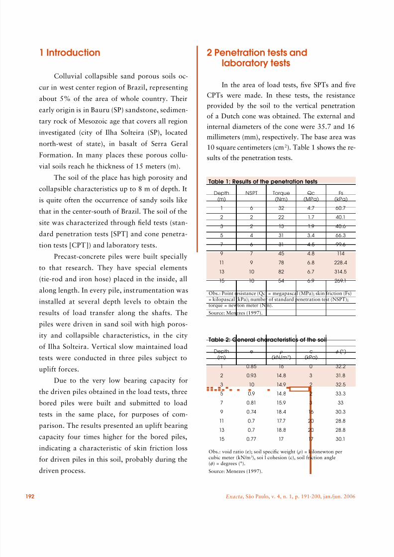
2 Penetration tests andlaboratory tests
In the area of load tests, five SPTs and five
CPTs were made. In these tests, the resistanceprovided by the soil to the vertical penetration
of a Dutch cone was obtained. The external and
internal diameters of the cone were 35.7 and 16
millimeters (mm), respectively. The base area was
10 square centimeters (cm2). Table 1 shows the re-
sults of the penetration tests.
Table 1: Results of the penetration tests
Depth(m) NSPT Torque(Nm) Qc(MPa) Fs(kPa)
1 6 32 4.7 60.7
2 2 22 1.7 40.1
3 2 13 1.9 40.6
5 4 31 3.4 66.3
7 6 31 4.5 99.6
9 7 45 4.8 114
11 9 78 6.8 228.4
13 10 82 6.7 314.5
15 10 54 6.9 269.1
Obs.: Point resistance (Qc) = megapascal (MPa); skin friction (Fs)= kilopascal (kPa); number of standard penetration test (NSPT);torque = newton meter (Nm).
Source: Menezes (1997).
Table 2: General characteristics of the soil
Depth(m)
e r (kN/m3)
c(kPa)
f (° )
1 0.85 16 0 32.2
2 0.93 14.8 3 31.8
3 10 14.9 2 32.5
5 0.9 14.8 2 33.3
7 0.81 15.9 3 33
9 0.74 18.4 16 30.3
11 0.7 17.7 20 28.8
13 0.7 18.8 20 28.8
15 0.77 17 17 30.1
Obs.: void ratio (e); soil specific weight ( r) = kilonewton percubic meter (kN/m3), soi l cohesion (c), soil friction angle(f) = degrees (°).
Source: Menezes (1997).
8/13/2019 Analysis of Uplift Loads of Precast-concrete Piles in Porous Soils
http://slidepdf.com/reader/full/analysis-of-uplift-loads-of-precast-concrete-piles-in-porous-soils 4/11
Artigos
193Exacta, São Paulo, v. 4, n. 1, p. 191-200, jan./jun. 2006
The laboratory tests were performed on the
samples extracted meter by meter from the pit
shaft. The consolidation tests, unconfined com-
pression and consolidated undrained triaxial
tests, were performed on undisturbed samples(Table 2).
3 Material and methods
According to following enumerations.
3.1 Characteristics andinstrumentation of the pilesThe piles had been manufactured and in-
strumented, being driving rig and presenting the
following characteristic materials: steel with fyk
= 1,500 MPa and concrete with fck ≥ 35 MPa,
having section of 0.17 x 0.17 square meter (m2)
and length of 13 m (Table 3).
The static instrumentation was constituted by
bars of steel where were put strain gages that were
concreted inside the piles in five levels. One level of
strain gauges was used, placed out of the soil influ-
ence, at the head of the piles, in order to allow the
determination of the value of Young’s module.For the law of Hooke (F = EE.e.A) considered
the module of elasticity (EE) and the area of the
section (A) constant for all the length of the pile,
stayed like variables the force (F) and the specific
deformation of the soil (e).
The value of EE for the first level was equal
the 38 gigapascal (GPa) and below the second level
of instrumentation equal 30 GPa.
3.2 Load testsSlow maintained load tests were performed
according Brazilian standard NBR-12131/97 (AS-
SOCIAÇÃO BRASILEIRA DE NORMAS TÉC-
NICAS, 1997).The system of reaction of the piles was
constituted by a metall ic beam of 7 m of length
and weight of 25 kN capable to support loads
of up to 1 meganewton (MN). Tie-rod had
been instal led in the piles of uplift and reaction
for permit the test of load to the traction. It
was utilized a hydraulic system (with manom-
eter and hydraulic bomb), that it possessed a
central hole for passage of the tie-rod in his
interior and being able to be applied loads of
up to 1 MN.
4. Results obtained
According to following enumerations.
4.1 collapse index
The laboratory tests conducted with in-undation in some pressures, have shown
that the soil is collapsible up to 7 m of depth
(Graphic 1).
Table 3: Characteristics of the piles
Pile Section(m)
Structuralload (kN)
weight(kg/m)
Area of thesection (cm2)
Uplift 0.17 400 73 0.029
Reaction 0.23 820 138 0.053
Source: Menezes (1997).
-1
0
1
2
3
4
5
6
7
8
9
0 100 200 30 0 400 500 600 700Inundation pressure (kPa)
C o l l a p s e ( % )
Graphic 1: Curves of collapse ofthe soil for some depths
Source: Menezes (1997).
8/13/2019 Analysis of Uplift Loads of Precast-concrete Piles in Porous Soils
http://slidepdf.com/reader/full/analysis-of-uplift-loads-of-precast-concrete-piles-in-porous-soils 5/11
194 Exacta, São Paulo, v. 4, n. 1, p. 191-200, jan./jun. 2006
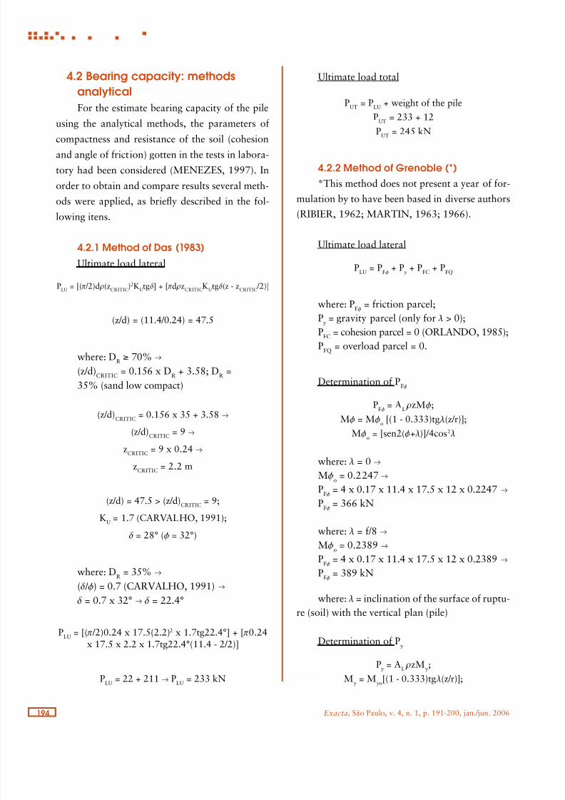
4.2 Bearing capacity: methods
analytical
For the estimate bearing capacity of the pile
using the analytical methods, the parameters of
compactness and resistance of the soil (cohesionand angle of friction) gotten in the tests in labora-
tory had been considered (MENEZES, 1997). In
order to obtain and compare results several meth-
ods were applied, as briefly described in the fol-
lowing itens.
4.2.1 Method of Das (1983)
Ultimate load lateral
PLU = [(p /2)d r(zCRITIC)2KUtgd] + [pd rzCRITICKUtgd(z - zCRITIC /2)]
(z/d) = (11.4/0.24) = 47.5
where: DR ≥ 70% T
(z/d)CRITIC = 0.156 x DR + 3.58; DR =
35% (sand low compact)
(z/d)CRITIC
= 0.156 x 35 + 3.58 T
(z/d)CRITIC
= 9 t
zCRITIC
= 9 x 0.24 T
zCRITIC
= 2.2 m
(z/d) = 47.5 > (z/d)CRITIC
= 9;
KU = 1.7 (CARVALHO, 1991);
d = 28° (f = 32°)
where: DR = 35% T
(d / f) = 0.7 (CARVALHO, 1991) T d = 0.7 x 32° t d = 22.4°
PLU
= [(p /2)0.24 x 17.5(2.2)2 x 1.7tg22.4°] + [p0.24x 17.5 x 2.2 x 1.7tg22.4°(11.4 - 2/2)]
PLU
= 22 + 211 T PLU
= 233 kN
Ultimate load total
PUT = PLU + weight of the pile
PUT
= 233 + 12
PUT = 245 kN
4.2.2 Method of Grenoble (*)
*This method does not present a year of for-
mulation by to have been based in diverse authors
(RIBIER, 1962; MARTIN, 1963; 1966).
Ultimate load lateral
PLU
= PFf
+ Pg + P
FC + P
FQ
where: PFf = friction parcel;Pg = gravity parcel (only for l > 0);
PFC = cohesion parcel = 0 (ORLANDO, 1985);PFQ = overload parcel = 0.
Determination of PFf
PFf
= AL rzMf;
Mf = Mfo [(1 - 0.333)tgl(z/r)];Mf
o = [sen2(f+l)]/4cos2l
where: l = 0 TMf
o = 0.2247 TPFf = 4 x 0.17 x 11.4 x 17.5 x 12 x 0.2247 TPFf = 366 kN
where: l = f/8 TMf
o = 0.2389 T
PFf = 4 x 0.17 x 11.4 x 17.5 x 12 x 0.2389 TPFf = 389 kN
where: l = inclination of the surface of ruptu-re (soil) with the vertical plan (pile)
Determination of Pg
Pg = A
L rzM
g ;
Mg = M
g o[(1 - 0.333)tgl(z/r)];
8/13/2019 Analysis of Uplift Loads of Precast-concrete Piles in Porous Soils
http://slidepdf.com/reader/full/analysis-of-uplift-loads-of-precast-concrete-piles-in-porous-soils 6/11
Artigos
195Exacta, São Paulo, v. 4, n. 1, p. 191-200, jan./jun. 2006
Mg o
= -0.5tgl T Mg o
= 0.035
Pg = 4 x 0.17 x 11.4 x 17.5 x 11.4 x 0.035 T
Pg = 54 kN
Determination of PLU
where: l = 0 T PLU = 366 kN
where: l = f /8 t
PLU = 389 + 54 t
PLU = 443 kN
Ultimate load total
PUT = PLU + weight of the pile
where: l = 0 t
PUT = 366 + 12 T
PUT = 378 kN
where: l = f /8 t PUT = 443 + 12 T
PUT = 455 kN
4.2.3 Method of Meyerhoffand Adams (1973)
Ultimate load lateral
PLU
= (CA + sVM
KUtgd)A
PLU
= (105 x 1.7tg28°)(4 x 0.17 x 11.4)
PLU
= 775 kN
Ultimate load total
PUT = PLU + weight of the pilePUT = 775 + 12 PUT = 787 kN
4.3 Bearing capacity:methods empiricalFor the estimate bearing capacity of the pile
the uplift, Décourt and Quaresma (1978) – on the
basis of tests SPT – and Velloso (1981) – on the ba-
sis of tests CPT – adopt a factor of security equal
0.7, in relation the formulas of bearing capacity
the compression (DANZIGER, 1983).
4.3.1 Method of Décourtand Quaresma (1978)
Ultimate load lateral
PLU = (f UpL)0.7
f U = (NSPTSIDE AVERAGE /3) + 1 = (6/3) + 1 = 3 t/m2 ou 30 kPa
PLU
= 30 x 4 x 0.17 x 11.4 x 0.7 = 163 kN
Ultimate load total
PUT = PLU + weight of the pileP
UT = 163 + 12
PUT
= 175 kN
4.3.2 Method of Velloso (1981)
Ultimate load lateral
PLU
= lapLf U
l = 0.7 (uplift piles)
a = 1f U = ALL = 113 kPa
PLU
= 0.7 x 1 x 4 x 0.17 x 11.4 x 113 = 613 kN
Ultimate load total
PUT
= PLU
+ weight of the pile
PUT = 613 + 12
PUT
= 625 kN
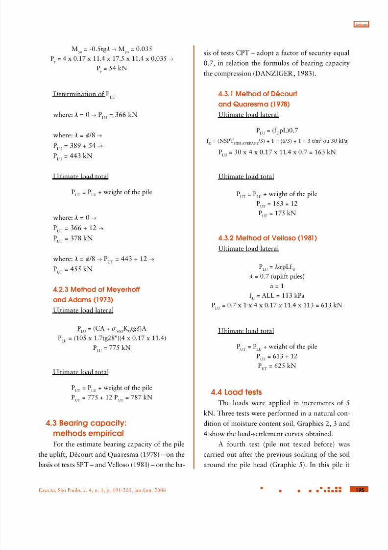
4.4 Load testsThe loads were applied in increments of 5
kN. Three tests were performed in a natural con-
dition of moisture content soil. Graphics 2, 3 and
4 show the load-settlement curves obtained.
A fourth test (pile not tested before) was
carried out after the previous soaking of the soil
around the pile head (Graphic 5). In this pile it
8/13/2019 Analysis of Uplift Loads of Precast-concrete Piles in Porous Soils
http://slidepdf.com/reader/full/analysis-of-uplift-loads-of-precast-concrete-piles-in-porous-soils 7/11
196 Exacta, São Paulo, v. 4, n. 1, p. 191-200, jan./jun. 2006
was opened a dig in the soil of 0.60 m of depth
and area of 1 x 1 m2. After that, inundation in
the soil was made, with controlled discharge. The
time of inundation of the soil was of 72 hours with
average discharge of 0.5 m3
/h.
4.5 Load transferDue to the low skin friction up to 8 m deep,
the analysis for the load transfer data, took into
account only two parts of the piles shaft. The first
being related to the head of the pile and the other
related to the intermediate portion of the pile. The
load distribution along piles is shown in Graphics
6, 7, 8 and 9.
0
10
20
30
40
50
0 5 10 15 20 25 30Load (kN)
S e t t l e m e n t ( m m )
Graphic 2: Load-settlement curve (Pile 1)
Source: Menezes (1997).
0
10
20
30
40
50
0 10 20 30 40 50 60Load (kN)
S e t t l e m e n t ( m
m )
Graphic 3: Load-settlement curve (Pile 2)
Source: Menezes (1997).
0
10
20
30
40
50
0 10 20 30 40 50 60 70Load (kN)
S e t t l e m e n t (
m m )
Graphic 4: Load-settlement curve (Pile 3)
Source: Menezes (1997).
0
10
20
30
40
50
0 10 20 30 40 50 60Load (kN)
S e t t l e m e n t ( m m )
Graphic 5: Load-settlement curve (Pile 4)
Source: Menezes (1997).
0.6
0 5 10 15 20 25Load (kN)
D e p t h ( m
)
0.8
12
Graphic 6: Load transfer results (Pile 1)
Source: Menezes (1997).
8/13/2019 Analysis of Uplift Loads of Precast-concrete Piles in Porous Soils
http://slidepdf.com/reader/full/analysis-of-uplift-loads-of-precast-concrete-piles-in-porous-soils 8/11
Artigos
197Exacta, São Paulo, v. 4, n. 1, p. 191-200, jan./jun. 2006
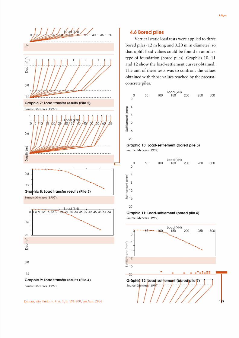
4.6 Bored pilesVertical static load tests were applied to three
bored piles (12 m long and 0.20 m in diameter) so
that uplift load values could be found in another
type of foundation (bored piles). Graphics 10, 11and 12 show the load-settlement curves obtained.
The aim of these tests was to confront the values
obtained with those values reached by the precast-
concrete piles.
0.6
0 5 10 15 20 25 30 35 40 45 50Load (kN)
D e p t h ( m )
0.8
12
Graphic 7: Load transfer results (Pile 2)
Source: Menezes (1997).
0.6
0 5 10 15 20 25 30 35 40 45 50 55 60 65Load (kN)
D e p t h ( m )
0.8
12
Graphic 8: Load transfer results (Pile 3)
Source: Menezes (1997).
0.6
0 3 6 9 12 15 18 21 24 27 30 33 36 39 42 45 48 51 54Load (kN)
D e p t h ( m
)
0.8
12
Graphic 9: Load transfer results (Pile 4)
Source: Menezes (1997).
0
4
8
12
16
20
0 50 100 150 200 250 300Load (kN)
S e t t l e m e n t ( m m )
Graphic 10: Load-settlement (bored pile 5)
Source: Menezes (1997).
0
4
8
12
16
20
0 50 100 150 200 250 300Load (kN)
S e t t l e m e n t ( m m )
Graphic 11: Load-settlement (bored pile 6)
Source: Menezes (1997).
0
4
8
12
16
20
0 50 100 150 200 250 300Load (kN)
S e t t l e m e n t ( m m )
Graphic 12: Load-settlement (bored pile 7)
Source: Menezes (1997).
8/13/2019 Analysis of Uplift Loads of Precast-concrete Piles in Porous Soils
http://slidepdf.com/reader/full/analysis-of-uplift-loads-of-precast-concrete-piles-in-porous-soils 9/11
198 Exacta, São Paulo, v. 4, n. 1, p. 191-200, jan./jun. 2006
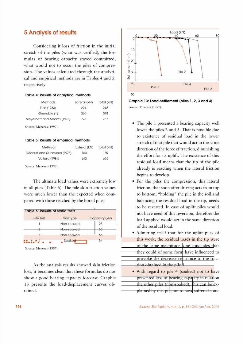
5 Analysis of results
Considering it loss of friction in the initial
stretch of the piles (what was verified), the for-
mulas of bearing capacity stayed committed,what would not to occur the piles of compres-
sion. The values calculated through the analyti-
cal and empirical methods are in Tables 4 and 5,
respectively.
The ultimate load values were extremely lowin all piles (Table 6). The pile skin friction values
were much lower than the expected when com-
pared with those reached by the bored piles.
As the analysis results showed skin friction
loss, it becomes clear that these formulas do not
show a good bearing capacity forecast. Graphic
13 presents the load-displacement curves ob-
tained.
• The pile 1 presented a bearing capacity well
lower the piles 2 and 3. That is possible due
to existence of residual load in the lower
stretch of that pile that would act in the same
direction of the force of traction, diminishing
the effort for its uplift. The existence of this
residual load means that the tip of the pile
already is reacting when the lateral friction
begins to develop.
• For the piles the compression, this lateralfriction, that soon after driving acts from top
to bottom, “holding” the pile in the soil and
balancing the residual load in the tip, needs
to be reverted. In case of uplift piles would
not have need of this reversion, therefore the
load applied would act in the same direction
of the residual load.
• Admitting itself that for the uplift piles of
this work, the residual loads in the tip wereof the same magnitude, one concludes that
they could of some form have influenced to
provoke the decrease resistance to the trac-
tion obtained in the pile 1.
• With regard to pile 4 (soaked) not to have
presented loss of bearing capacity in relation
the other piles (non-soaked), this can be ex-
plained by this pile not to have suffered some
Table 4: Results of analytical methods
Methods Lateral (kN) Total (kN)
Das (1983) 224 245
Grenoble (*) 366 378
Meyerhoff and Adams (1973) 775 787
Source: Menezes (1997).
Table 5: Results of empirical methods
Methods Lateral (kN) Total (kN)
Décourt and Quaresma (1978) 163 175
Velloso (1981) 613 625
Source: Menezes (1997).
Table 6: Results of static tests
Pile test Soil type Capacity (kN)
1 Non-soaked 25
2 Non-soaked 50
3 Non-soaked 65
4 Soaked 54
Source: Menezes (1997).
0
10
20
30
40
50
0 20 40 60 80Load (kN)
S e t t l e m e n t ( m
m )
Pile 1Pile 3
Pile 2
Pile 4
Graphic 13: Load-settlement (piles 1, 2, 3 and 4)
Source: Menezes (1997).
8/13/2019 Analysis of Uplift Loads of Precast-concrete Piles in Porous Soils
http://slidepdf.com/reader/full/analysis-of-uplift-loads-of-precast-concrete-piles-in-porous-soils 10/11
Artigos
199Exacta, São Paulo, v. 4, n. 1, p. 191-200, jan./jun. 2006
anomaly from the soil when of its driving.
The same it did not occur with the other piles
(1, 2 and 3) that had short values of bearing
capacity.
• The great vibrations during the driving of thepiles, provoke for the trepidation to not adhe-
sion of the pile to the soil, due its characteris-
tics of high porosity, not having a subsequent
recuperation of the interaction pile-soil.
• The hypothesis of the effect of the form of
installation of the pile to have provoked the
loss of lateral friction is to more probable.
During the driving which was observed that
it was an “empty” between the pile and thesoil reached 2 m of depth. Accounts of en-
gineers and operators of driving machines
had indicated that this fact generally occurs
when are nailed piles in this type of soil of
São Paulo State. Procedures of if playing sand
in the head of the piles during the driving, to
go itself filling the emptinesses between the
pile and the soil, had been commented some
engineers.
6 Final considerations
• In this work was verified that for that type of
soil (porous), the collapse index is higher in
the first meters
• The lower values of bearing capacity for the
three precast piles, in comparison with bored
piles, indicate that the precast piles used are
not adequate for soil friction requirement in
that soil.
• The field analysis and observations indicate
that the vibrations due to the driving process
cause irrecoverable lateral pile displacement
from the soil at a depth of some meters
• The soaking of the surface soil around the
pile head during 48 hours causes a 50% skin
friction loss up to 8 m deep.
• As demonstrated, when submitted to uplift
load the precast piles showed low bearing ca-pacity. With the ultimate load values for both
types of piles, one can better interpret the re-
sults.
• The bored piles, submitted the same con-
ditions of in situ that the precast-concrete
piles, indicated to its good capacity of load
to the uplift.
References
ASSOCIAÇÃO BRASILEIRA DE NORMASTÉCNICAS. NBR-12131/97: provas de carga estáticasem estacas. Rio de Janeiro: ABNT, 1997.
CARVALHO, D. Análise de cargas últimas a traçãode estacas escavadas, instrumentadas, em CampoExperimental de São Carlos (SP). 1991. Tese (Doutoradoem Engenharia Civil)-Escola de Engenharia de SãoCarlos, Universidade de São Paulo, São Carlos, 1991.
DANZIGER, F. A. B. Capacidade de carga de fundaçõessubmetidas a esforços verticais de tração. 1983.Tese (Doutorado em Engenharia Civil)-Coordenaçãodos Programas de Pós-Graduação em Engenharia,Universidade Federal do Rio de Janeiro, Rio de Janeiro,1983.
DAS, B. M. J. et al. A procedure for estimation of upliftcapacity of rough piles. Soils and Foundations, Tokyo,vol. 23, no. 3, pp. 122-126, 1983.
DÉCOURT, L.; QUARESMA, A. R. Capacidadede carga de estacas a partir de valores de SPT. In:CONGRESSO BRASILEIRO DE MECÂNICA DOS
SOLOS E ENGENHARIA DE FUNDAÇÕES, 6., 1978,Rio de Janeiro. Anais... Rio de Janeiro: 1978. vol. 1, pp.45-53.
MARTIN, D. Étude à la rupture de différents ancragessollicitées verticalement . 1966. Thése (Doctorat deIngénieur)-Faculté des Sciences de Grenoble, Grenoble,1966.
______. Foundations profondes sollicitées àl´arranchement en milieu cohérent tridimensional . 1963.Thése (Doctorat de Spécialité)-Faculté des Sciences deGrenoble, Grenoble, 1963.
8/13/2019 Analysis of Uplift Loads of Precast-concrete Piles in Porous Soils
http://slidepdf.com/reader/full/analysis-of-uplift-loads-of-precast-concrete-piles-in-porous-soils 11/11
200 Exacta, São Paulo, v. 4, n. 1, p. 191-200, jan./jun. 2006
MENEZES, S. M. Análise do comportamento deestacas pré-moldadas em solo de alta porosidade dointerior do Estado de São Paulo. Tese (Doutorado emEngenharia Civil)-Escola Politécnica, Universidade deSão Paulo, São Paulo, 1997.
MEYERHOFF, G. G.; ADAMS, J. I. The ultimate uplift
capacity of fundations. Canadian Geotechnical Journal ,Ottawa, vol. 5, no. 4, pp. 224-244, 1973.
ORLANDO, C. Fundações submetidas a esforçosverticais axiais de tração. Análise de provas de carga detubulões em areias porosas. 1985. Tese (Doutorado emEngenharia Civil)-Escola Politécnica, Universidade deSão Paulo, São Paulo, 1985.
RIBIER, B. Étude des argiles fortement plastiques etessais de soulèvement des pieus. 1962. Thése (Doctoratde Spécialité)-Faculté des Sciences de Grenoble,Grenoble, 1962.
VELLOSO, P. P. C. Considerações sobre a estimativada capacidade de suporte e dos deslocamentos vertical e
horizontal de estacas em solo. 1. ed. Brasília: UnB, 1981.
Recebido em: 7 abr. 2006 / aprovado em: 29 jun. 2006
Para referenciar este texto
MENEZES, S. M.; CARVALHO, D. de;ALBUQUERQUE, P. J. R. de. Analysis of uplift loadsof precast-concrete piles in porous soils. Exacta, SãoPaulo, v. 4, n. 1, p. 191-200, jan./jun. 2006.