universidade de lisboa faculdade de cienciasˆrepositorio.ul.pt › bitstream › 10451 › 10792...
TRANSCRIPT

UNIVERSIDADE DE L ISBOAFaculdade de Ciencias
Departamento de Informatica
INACCESSIBILITY IN WIRELESS SENSORNETWORKS
Andr e Alexandre Margarido Taborda Vaz Guerreiro
DISSERTACAO
MESTRADO EM ENGENHARIA INFORMATICAEspecializacao em Arquitectura, Sistemas e Redes de Computadores
2013


UNIVERSIDADE DE L ISBOAFaculdade de Ciencias
Departamento de Informatica
INACCESSIBILITY IN WIRELESS SENSORNETWORKS
Andr e Alexandre Margarido Taborda Vaz Guerreiro
DISSERTACAO
MESTRADO EM ENGENHARIA INFORMATICAEspecializacao em Arquitectura, Sistemas e Redes de Computadores
Dissertacao orientada pelo Prof. Doutor Jose Manuel de Sousa de Matos Rufinoe co-orientada pelo Mestre Jeferson Luiz Rodrigues Souza
2013


Acknowledgments
During the course of the work which led to the present dissertation, including the
curricular part of the Masters programme, there are many people to which I am most
thankful for all the different kinds of support they gave me.May my gratitude towards
them remain forever patent in these lines.
Firstly, I would like to thank my advisor, Prof. Jose Rufino and my co-advisor Jeferson
L. R. Souza, for they crucial help during the development of this thesis. Their remarks
and suggestions have always contributed to the increase of my knowledge and to develop
further my work. Theirs dedication and support while I was writing this thesis and related
articles was truly important. I think i couldn’t get better orientation than which was given
to me. Their availability, good advices, and friendship were extremely important for me.
Secondly I would like to thank Navigators research group andall of the LaSIGE fel-
lows for the interesting and constructive discussions where I learnt a lot.
Thirdly, I would like to thank all my colleagues and friends from Lab 8.2.25, for their
help and support, and priceless moments of fellowship.
Last, but not least, the biggest “Thank you”of the world goesfor my family. My
mother Elsa, my father Manuel and my grandmother Maria. Theyhave always been there
for me and with their motivation and enthusiasm forced me to keep working even in the
hardest moments, and to always choose my own way to achieve the proposed goals. It is
not too much to say that I couldn’t do this without them.
This work was partially supported: by the EC, through project IST-FP7-STREP-288195 (KARYON);
by FCT/DAAD, through the transnational cooperation project PROPHECY; and by FCT, through the project
PTDC/EEI-SCR/3200/2012 (READAPT) and the Multiannual Funding Program.
iii


A minha famılia e amigos.


Abstract
Wireless networks are seen as the communication networks ofthe future, providing
communication capabilities where cables are not able to be used. Wireless technologies
enable network flexibility and mobility, and reduce size, weight, and power consumption
(SWaP) of communication devices. The IEEE 802.15.4 standard was designed to support
the specification of wireless sensor networks (WSNs) and wireless sensor and actuator
networks (WSANs), where is emerging their utilization within environments with real-
time requirements, such as industrial and aerospace.
The medium access control (MAC) layer is the control foundation of the network
communication services. Disturbances in the MAC layer operation may lead to a network
inaccessibility scenario, which consists in a temporary absence of network communica-
tion although the network is not considered failed. Examples of such disturbances are
electromagnetic noise interference, glitches in the wireless device circuitry, or even ob-
stacles in the communication path.
A previous theoretical study indicates the occurrence of periods of network inacces-
sibility as a source of MAC transmission protocol delays which may induce application
deadline misses which that compromise the dependability and timeliness properties of the
whole networked system. Thus, this work aims to validate that previous study using the
network simulator NS-2.
The NS-2 simulator is a widely used tool supporting the simulation of IEEE 802.15.4
wireless networks. However, we discovered that its compliance to the IEEE 802.15.4 stan-
dard is imperfect. In order to perform the validation of the theoretical characterisation of
network inaccessibility new mechanisms need to be introduced in the IEEE 802.15.4 sim-
ulation model. These improvements comprises: the support for real-time transmissions,
through the incorporation of the contention free period (CFP) and of guaranteed time slot
(GTS) ; IEEE 802.15.4 standard management operations not implemented in the official
NS-2 release; A flexible tool capable of re-create the inaccessibility events and simulate
different error conditions on the network, which include the Fault Injector and temporal
and energetic analysis tool;
Keywords: wireless networks; network inaccessibility; dependability; timeliness;
real-time;
vii


Resumo
As redes sem fios tem sido encaradas como as redes de comunicacao do futuro, for-
necendo capacidades de comunicacao onde os cabos nao podem de ser utilizados. As
tecnologias sem fio permitem flexibilidade e mobilidade na rede como tambem reduzir o
tamanho, peso e consumo energetico (SWaP) dos dispositivos de comunicacao.
A norma IEEE 802.15.4 foi projetada para suportar a especificacao de redes de senso-
res sem fio (WSNs) e redes de sensores e atuadores sem fios (WSANs), e a sua utilizacao
esta a emergir em ambientes com requisitos de tempo real, tais como o industrial e aero-
espacial.
A camada de controlo de acesso ao meio (MAC) e o alicerce de controlo dos servicos
de comunicacao da rede. Disturbios no funcionamento desta camada podem levar a rede a
entrar num estado apelidado de inacessibilidade, este caracteriza-se numa falta temporaria
de comunicacao na rede, embora nao se considere que a redefalhou. Exemplos de tais
perturbacoes sao ondas eletromagneticas, falhas no circuito de dispositivos sem fios, ou
ate mesmo obstaculos no caminho de comunicacao.
Um estudo teorico anterior indica a ocorrencia de inacessibilidade como fontes de
atraso portanto, falhas no cumprimento de prazos que podem comprometer proprieda-
des de confiabilidade e pontualidade de todo o sistema. Assim, este trabalho tem como
objetivo validar que o estudo anterior, utilizando o simulador de rede NS-2.
O simulador de rede NS-2 e uma ferramenta amplamente utilizada no suporte a simulacao
de redes sem fio IEEE 802.15.4. No entanto, descobrimos que n˜ao se encontra totalmente
em conformidade com a norma IEEE 802.15.4. Com o intuito de efetuar a validacao
dos modelos de inacessibilidade, novos mecanismos devem ser introduzidos no modelo
de simulacao referente ao IEEE 802.15.4. Estes melhoramentos compreendem: Suporte
para transmissoes de tempo real, atraves da incorporac˜ao do mecanismo de acesso livre
de contencao (CFP) e do intervalo de tempo de acesso garantido (GTS); Desenvolver
as operacoes de gestao normalizadas nao concretizadasno modulo IEEE 802.15.4 pre-
sente na versao oficial do NS-2;Adicao de novos recursos necessarios para a avaliacao da
rede em condicoes de erro, mais especificamente, um injetor de faltas, e um modulo de
contabilizacao temporal e energetico.
Palavras-chave:redes sem fios; inacessibilidade; confiabilidade; pontualidade;
tempo-real;
ix


Resumo alargardo
As redes sem fios tem sido encaradas como as redes de comunicacao do futuro, for-
necendo capacidades de comunicacao onde os cabos nao podem de ser utilizados. As
tecnologias sem fio permitem flexibilidade e mobilidade na rede como tambem reduzir o
tamanho, peso e consumo energetico (SWaP) dos dispositivos de comunicacao. Devido as
suas caracterısticas unicas, ha um grande interesse no desenvolvimento de aplicacoes que
utilizem Redes de Sensores Sem Fios e Redes de Sensores e Actuadores Sem Fios em di-
ferentes sectores, tais como monitorizacao de recursos naturais, aeroespacial, automovel
e industrial. A maioria destes ambientes tem restricoesde comunicacao em tempo real, o
que implica que as Rede de Sensores Sem Fios e as Redes de Sensores e Actuadores Sem
Fios devem ser capazes de fornecer suporte a servicos de comunicacao em tempo real e
dar garantias acerca dos limites do tempo de transmissao.
No entanto, o meio de comunicacao aberto e partilhado das redes sem fio e alta-
mente suscetıvel a interferencias eletromagneticas, ea obstaculos existentes no caminho
da comunicacao. Estes problemas podem perturbar as comunicacoes realizadas pela ca-
mada de controle de acesso ao meio (MAC). Melhorar a previsibilidade temporal e a
confiabilidade dos servicos de nıvel MAC e de extrema importancia de forma a proporci-
onar um servico de transmissao de dados em tempo real eficiente atraves das redes sem
fios.
Existem diversos estudos focados no suporte de servicos decomunicacao fiavel e
tempo real em comunicacoes em redes sem fios, mais propriamente ao nıvel mais baixo
da pilha de protocolos de comunicacao. Contudo esses estudos dao pouca ou nenhuma
importancia aos aspetos de fiabilidade da camada de acesso ao meio e seus servicos. No
entanto a confiabilidade e a pontualidade sao essenciais para assegurar a capacidade de
resposta e recuperacao da normal operacao da rede quando esta e sujeita a condicoes de
erro.
Tais erros podem afetar a operacao da camada MAC e induzir paragens temporarias da
rede, um fenomeno que designamos por inacessibilidade, e que pode impedir a operacao
da rede em tempo real.
Um estudo teorico anterior indica a ocorrencia de inacessibilidade como fontes de
atraso portanto, falhas no cumprimento de prazos que podem comprometer propriedades
de confiabilidade e pontualidade de todo o sistema.
xi
Este estudo representa uma motivacao para a investigac˜ao em curso que aborda o
teste e avaliacao de redes de sensores sem fios e redes de sensores e actuadores sem fios
atraves do uso de simuladores de rede, nos quais adoptamos anorma IEEE 802.15.4 e o
seu conhecido potencial para suportar o trafego de tempo real (atraves da atribuicao de
acesso a rede exclusivo), como um caso de estudo.
A utilizacao de simuladores representa uma forma adequada de testar e avaliar a
dinamica de uma rede em diferentes condicoes ambientais. Existem varios simulado-
res de rede disponıveis, alguns com licenca comercial, como o OPNET, e outros com
codigo-fonte aberto ou de licenca academica, como Omnet++ , Prowler, TOSSIM e NS-
2. O simulador de rede NS-2 e das ferramentas de simulacaomais amplamente aceites e
utilizadas na comunidade cientıfica, e uma plataforma de codigo-fonte aberto e de arqui-
tetura modular, suporta a simulacao de redes de sensores sem fios e redes de sensores e
actuadores sem fios atraves da norma IEEE 802.15.4.
Embora o NS-2 possua um modulo respeitante a norma IEEE 802.15.4, este modulo
nao vem com um suporte nativo para aplicacoes com necessidades de comunicacao em
tempo real, como por exemplo a simulacao de um perıodo livre de contencao (CFP) no
qual e possıvel alocar intervalos de tempo para acesso exclusivo a rede.
E o nosso objetivo ultrapassar a limitacao existente no m´odulo IEEE 802.15.4 do si-
mulador NS-2, que, originalmente, apenas permite comunicacoes baseadas em contencao.
Assim, este trabalho apresenta melhorias no modulo IEEE 802.15.4 NS-2 de forma a
que este proporcione melhor suporte ao teste, simulacao eavaliacao das redes de sensores
sem fios que respeitam a norma IEEE 802.15.4 e que possuem requisitos de tempo real.
No nosso trabalho incluımos todas as funcoes de gestao necessarias para suportar o uso
de intervalos de tempo de acesso garantidos (GTS) para as transmissoes de tramas.
A concretizacao destes mecanismos foi avaliada e validada atraves de casos de teste,
utilizando diferentes cargas de rede e metricas de desempenho, tais como a taxa de en-
trega, latencia e consumo de energia, permitindo uma melhor caracterizacao das redes
IEEE 802.15.4 no suporte de comunicacoes em tempo real.
Depois de melhorar o suporte do NS-2 para a avaliacao de redes IEEE 802.15.4 com
requisitos de tempo real, novos recursos foram necessarios para complementar o modelo
de erro atual do simulador NS-2, e para permitir a avaliacao da rede sob condicoes de erro
e mais especificamente eventos de inacessibilidade da rede.
Para validar o nosso estudo, desenvolveu-se uma ferramentaflexıvel, capaz de recriar
os eventos de inacessibilidade e simular diferentes condic¸oes de erro na rede, apelidada
de injetor de faltas. O modelo de erro atual presente no simulador nao permite afetar uma
trama especıfica, como uma trama MAC por exemplo.
Por isso, desenvolvemos um novo modulo para injetar falhase analisar o comporta-
mento da rede sob condicoes de erro. Como resultado geral,este trabalho tem o com-
promisso de estabelecer uma plataforma robusta de estudo deforma a proporcionar uma
xii
melhor compreensao dos aspetos temporais das redes IEEE 802.15.4.
Assim o nosso principal objetivo neste trabalho e atravesde simulacao validar os resul-
tados obtidos no anterior estudo teorico sobre a inacessibilidade em redes de comunicacoes
sem fios IEEE 802.15.4 pelo melhoramento das ferramentas de simulacao existentes.
As principais contribuicoes do trabalho descrito nesta tese incluem:
• Avaliar o simulador de rede NS-2 identificando as suas limitacoes
• Melhoramentos no modulo IEEE 802.15.4 do NS-2 de forma a proporcionar um
melhor suporte a simulacao de redes com requisitos de tempo real.
• Incorporacao dos mecanismos de CFP e GTS, atraves da implementacao do GTS
dentro do modulo IEEE 802.15.4 presente no NS-2.
• Desenvolver as operacoes de gestao normalizadas nao concretizadas no modulo
IEEE 802.15.4 presente na versao oficial do NS-2.
• Adicao de novos recursos necessarios para a avaliacao da rede em condicoes de
erro, mais especificamente, um injetor de faltas, e um modulo de contabilizacao
temporal e energetico.
• A utilizacao destes recursos na validacao de modelos teoricos existentes respeitan-
tes a avaliacao da inacessibilidade em redes IEEE 802.15.4.
Foram produzidos varios artigos no ambito deste trabalho, alguns deles apresentando
um trabalho preliminar sobre o assunto abordado, e os restantes resultantes do trabalho
aqui descrito. Os seguintes documentos foram publicados emcongressos nacionais:
• Jeferson L. R. Souza, Andre Guerreiro, Jose Rufino, “Characterizing Inaccessibility
in IEEE 802.15.4 Through Theoretical Models and SimulationTools”, em INForum
2012 - Simposio de Informatica, Lisboa, Portugal, Set. 2012.
• Andre Guerreiro, Jeferson L. R. Souza, Jose Rufino, “Improving NS-2 Network Si-
mulator for IEEE 802.15.4 standard operation ”, em INForum 2013 - Simposio de
Informatica,Evora, Portugal, Set. 2013.
• Andre Guerreiro, Jeferson L. R. Souza, Jose Rufino, “Improving NS-2 Network Si-
mulator to evaluate IEEE 802.15.4 wireless networks under error conditions”, em
SENSORNETS 2014 - International Conference on Sensor Networks, Lisboa, Por-
tugal, Jan. 2014.
xiii

Contents
List of Figures xvii
List of Tables xix
Abbreviations xxi
1 Introduction 1
1.1 Motivation . . . . . . . . . . . . . . . . . . . . . . . . . . . . . . . . . . 1
1.2 Objectives . . . . . . . . . . . . . . . . . . . . . . . . . . . . . . . . . . 3
1.3 Contributions . . . . . . . . . . . . . . . . . . . . . . . . . . . . . . . . 3
1.4 Institutional context . . . . . . . . . . . . . . . . . . . . . . . . . . . .. 4
1.5 Publications . . . . . . . . . . . . . . . . . . . . . . . . . . . . . . . . . 4
1.6 Document structure . . . . . . . . . . . . . . . . . . . . . . . . . . . . . 5
2 Background Context 7
2.1 The IEEE 802.15.4 Standard . . . . . . . . . . . . . . . . . . . . . . . . 7
2.1.1 Frame Format . . . . . . . . . . . . . . . . . . . . . . . . . . . . 9
2.1.2 Contention Access Period (CAP) . . . . . . . . . . . . . . . . . . 10
2.1.3 Contention Free Period (CFP) . . . . . . . . . . . . . . . . . . . 11
2.2 A Survey of Simulators for Wireless Sensor Networks . . . .. . . . . . . 11
2.3 NS-2 Network Simulator . . . . . . . . . . . . . . . . . . . . . . . . . . 12
2.3.1 NS-2 Error Model . . . . . . . . . . . . . . . . . . . . . . . . . 13
2.3.2 NS-2 Energy Model . . . . . . . . . . . . . . . . . . . . . . . . 14
2.3.3 IEEE 802.15.4 NS-2 Simulator Module . . . . . . . . . . . . . . 14
2.4 Summary . . . . . . . . . . . . . . . . . . . . . . . . . . . . . . . . . . 16
3 Inaccessibility in Wireless Sensor Networks 17
3.1 Introduction . . . . . . . . . . . . . . . . . . . . . . . . . . . . . . . . . 17
3.2 Preliminary Work . . . . . . . . . . . . . . . . . . . . . . . . . . . . . . 18
3.2.1 System Model . . . . . . . . . . . . . . . . . . . . . . . . . . . 18
3.2.2 Network inaccessibility . . . . . . . . . . . . . . . . . . . . . . . 20
3.2.3 Theoretical modeling of network inaccessibility in IEEE 802.15.4 20
xv

3.3 Summary . . . . . . . . . . . . . . . . . . . . . . . . . . . . . . . . . . 22
4 Improving the IEEE 802.15.4 NS-2 simulation module for real-time operation 234.1 Problem Definition . . . . . . . . . . . . . . . . . . . . . . . . . . . . . 23
4.2 Incorporating and enhancing MAC Management actions according to the
Standard . . . . . . . . . . . . . . . . . . . . . . . . . . . . . . . . . . . 23
4.3 CFP and GTS implementation in NS-2 . . . . . . . . . . . . . . . . . . .25
4.4 Design and implementation of the solution . . . . . . . . . . . .. . . . . 26
4.5 Data Analysis . . . . . . . . . . . . . . . . . . . . . . . . . . . . . . . . 27
4.6 Evaluation metrics for an effective real-time communication in Wireless
Sensor Networks . . . . . . . . . . . . . . . . . . . . . . . . . . . . . . 27
4.7 NS-2 Network Simulation Results . . . . . . . . . . . . . . . . . . . .. 28
4.7.1 Simulation Setup . . . . . . . . . . . . . . . . . . . . . . . . . . 29
4.7.2 Simulation Results . . . . . . . . . . . . . . . . . . . . . . . . . 30
4.8 Summary . . . . . . . . . . . . . . . . . . . . . . . . . . . . . . . . . . 31
5 Evaluating Inaccessibility Scenarios through Fault Injection 335.1 Problem Definition . . . . . . . . . . . . . . . . . . . . . . . . . . . . . 33
5.2 Injecting faults to simulate accidental errors on the network operation . . 34
5.3 Temporal and Energetic Analysis under error conditions. . . . . . . . . 36
5.4 Design and implementation of the solution . . . . . . . . . . . .. . . . . 37
5.5 Simulating Inaccessibility Scenarios . . . . . . . . . . . . . .. . . . . . 38
5.6 Inaccessibility Results . . . . . . . . . . . . . . . . . . . . . . . . . .. 40
5.6.1 Simulation Setup . . . . . . . . . . . . . . . . . . . . . . . . . . 40
5.6.2 Simulation Results . . . . . . . . . . . . . . . . . . . . . . . . . 41
5.7 Summary . . . . . . . . . . . . . . . . . . . . . . . . . . . . . . . . . . 47
6 Conclusion 49
Bibliography 54
xvi

List of Figures
1.1 WSN and WSAN Real-Time Applications . . . . . . . . . . . . . . . . 2
2.1 Superframe structure . . . . . . . . . . . . . . . . . . . . . . . . . . . . 8
2.2 General MAC frame format and format of the Frame Control field . . . . 9
2.3 NS-2 Architecture [13] . . . . . . . . . . . . . . . . . . . . . . . . . . . 13
2.4 NS-2 Error Models. . . . . . . . . . . . . . . . . . . . . . . . . . . . . 14
2.5 NS-2 IEEE 802.15.4 module architecture. . . . . . . . . . . . . .. . . . 15
3.1 Hidden Node Problem . . . . . . . . . . . . . . . . . . . . . . . . . . . 17
3.2 Mobile Node Problem . . . . . . . . . . . . . . . . . . . . . . . . . . . . 17
3.3 The graphical representation of a wireless network segment. . . . . . . . 19
4.1 Class diagram of changed classes on native IEEE 802.15.4module . . . 27
4.2 Data Frame Delivery Ratio comparison between transmission during CAP
and CFP . . . . . . . . . . . . . . . . . . . . . . . . . . . . . . . . . . 30
4.3 Data frame transmission Latency comparison between transmission dur-
ing CAP and CFP . . . . . . . . . . . . . . . . . . . . . . . . . . . . . . 30
4.4 Energy consumption per node for data transmission during CAP and CFP 31
5.1 New Features in IEEE 802.15.4 module . . . . . . . . . . . . . . . . .. 33
5.2 Fault Injector scheme . . . . . . . . . . . . . . . . . . . . . . . . . . . . 34
5.3 Fault Injector Class Model . . . . . . . . . . . . . . . . . . . . . . . . .37
5.4 Inaccessibility Scenarios comparison between Theoretical and Simulated
worst case and BO=SO=4 andTBI = 0.240s . . . . . . . . . . . . . . . . 41
5.5 Normalized Inaccessibility Scenarios comparison between Theoretical and
Simulated worst case and BO=SO=4 andTBI = 0.240s . . . . . . . . . . 42
5.6 Inaccessibility Scenarios comparison between Theoretical and Simulated
worst case and BO=SO=3 andTBI = 0.120s . . . . . . . . . . . . . . . . 43
5.7 Normalized Inaccessibility Scenarios comparison between Theoretical and
Simulated worst case and BO=SO=3 andTBI = 0.120s . . . . . . . . . . 44
5.8 Energy analysis consumption of Inaccessibility Scenarios with BO=4 . . 46
5.9 Energy analysis consumption of Inaccessibility Scenarios with BO=3 . . 46
xvii


List of Tables
2.1 Relevant time-related constants of IEEE 802.15.4 Standard . . . . . . . . 8
2.2 Values of the Frame Type field . . . . . . . . . . . . . . . . . . . . . . . 9
2.3 MAC command frames . . . . . . . . . . . . . . . . . . . . . . . . . . . 10
2.4 Simulators comparison . . . . . . . . . . . . . . . . . . . . . . . . . . . 11
2.5 Parameters for the energy model configuration . . . . . . . . .. . . . . 14
3.1 Easy-to-use formulas defining the durations of periods of network inac-
cessibility . . . . . . . . . . . . . . . . . . . . . . . . . . . . . . . . . . 21
4.1 NS-2 IEEE 802.15.4 Module behaviour comparison . . . . . . .. . . . . 24
4.2 Simulation Parameters . . . . . . . . . . . . . . . . . . . . . . . . . . . 29
5.1 MAC frame types . . . . . . . . . . . . . . . . . . . . . . . . . . . . . . 39
5.2 Simulation Parameters for Inaccessibility Scenarios with BO=SO=4 . . . 40
5.3 Theoretical best and worst case and simulated results for each network
inaccessibility scenario with BO=SO=4 andTBI = 0.240s . . . . . . . . . 41
5.4 Normalized theoretical best and worst case results for each network inac-
cessibility scenario with BO=SO=4 andTBI = 0.240s . . . . . . . . . . . 43
5.5 Simulation Parameters for Inaccessibility Scenarios with BO=SO=3 . . . 44
5.6 Theoretical best and worst case and simulated results for each network
inaccessibility scenario with BO=SO=3 andTBI = 0.120s . . . . . . . . . 45
5.7 Normalized theoretical best and worst case results for each network inac-
cessibility scenario with BO=SO=3 andTBI = 0.120s . . . . . . . . . . . 45
xix


Abbreviations
BI beacon interval.
CAP Contention Access Period.
CBR Constant Bit Rate traffic.
CFP Contention Free Period.
CSMA/CA Carrier Sense Multiple Access with Collision Avoidance.
DFDR Data Frame Delivery Ratio.
GTS Guaranteed Time Slot.
LLC Logical Link Control.
MAC Medium Access Control.
NAM Network Animator.
OTcl Object-oriented Tool Command Language.
PHY Physical layer.
RTS/CTS Request to Send / Clear to Send.
SSCS Service Specific Convergence Sub-layer.
SWaP size, weight, and power consumption.
WnS Wireless network Segment.
WSAN Wireless Sensor and Actuator Network.
WSN Wireless Sensor Network.
xxi

xxii
Chapter 1
Introduction
1.1 Motivation
Wireless networks technology are seen as the future of communications. Mobility, size,
weight, and power consumption (SWaP), and the absence of cable infrastructure are some
fundamental advantages of wireless communications. Due totheir unique features, there
is a huge interest in developing applications that use Wireless Sensor Networks (WSNs)
and Wireless Sensor and Actuator Networks (WSANs) in different sectors such as natural
resources monitoring [19], aerospace [34], vehicular [8],and industrial [30] as illustrated
in figure 1.1. Most of these environments have real-time communication constraints,
which implies that the WSNs and WSANs must be capable to provide support on real-
time communication services and provide guarantees about transmission time bounds.
However, the open and shared communication medium used by wireless networks is
highly susceptible to electromagnetic interferences, andobstacles on the communication
path, which may disturb the communications performed by theMedium Access Control
(MAC) layer. Improving the timeliness and dependability ofMAC level services is of
utmost importance to provide a real-time data transmissionservice on wireless communi-
cations.
There are many studies in wireless communications focused in the provision of reli-
able and real-time communication services at the lowest level of the protocol stack [9, 29,
10]. However these studies pay little or no attention to the dependability aspects of MAC
sublayer and its services, which are essential to assure thetimeliness and resilience of the
network when operating under error conditions.
Such faults may affect the MAC layer operation itself and induce temporary network
partitioning, dubbed network inaccessibility [39], whichimposes impairments fulfilling
network operation with real-time properties. A previous theoretical study [31] indicates
that the occurrence of network inaccessibility may be a source of transmission protocol
delays, which may induce application deadline misses that may compromise the depend-
1

Chapter 1. Introduction 2
Figure 1.1: WSN and WSAN Real-Time Applications
ability and timeliness properties of the whole networked system.
This study represents a motivation for the current researchon the test and evaluation
of WSNs and WSANs through network simulators, where we take the IEEE 802.15.4
network standard and his potential to support real-time traffic (through the allocation of
exclusive network access) as a case study.
The use of network simulators is a suitable tool to test and evaluate network be-
haviours using different environmental conditions. Thereare several network simulators
available [16], some with commercial license, such as OPNET[24], and others with open
source or academic license, like OMNeT++ [23], Prowler [26], TOSSIM [18], and NS-
2 [21]. The NS-2 simulator is the most accepted and widely used network simulation tool
on the literature, being open source and modular, supporting the simulation of WSNs and
WSANs through the IEEE 802.15.4 standard [11].
Although NS-2 has an IEEE 802.15.4 module [41], this module does not have a native
support for features that address real-time aspects of communications, such as emulation
of a Contention Free Period (CFP) where time slots can be allocated for exclusive access
to the network. One objective is to overcome the existing limitation which, natively, only
allow contention-based communications in the IEEE 802.15.4 NS-2 module.
Therefore, this work presents improvements in the IEEE 802.15.4 NS-2 module to
provide a better support for the test, simulation and evaluation of IEEE 802.15.4 networks
with real-time requirements. We include all the managementfunctions needed to support

Chapter 1. Introduction 3
the use of Guaranteed Time Slot (GTS) for frame transmissions, adapting and extending
an implementation of a CFP module proposed by [5]. We evaluate and validate our imple-
mentation through test cases that uses different network loads, and performance metrics
such as delivery ratio, latency, and energy consumption, allowing a better characterization
of IEEE 802.15.4 networks in the support of real-time communications.
After enhancing the NS-2 support to the evaluation of IEEE 802.15.4 networks with
real-time requirements, new features are needed to complement the current NS-2 error
model, and allow the evaluation of the network under error conditions and more specifi-
cally network inaccessibility events.
To validate our study we developed a flexible tool capable of re-create the inaccessi-
bility events and simulate different error conditions on the network, dubbed fault injector.
The current error model cannot affect a specific frame such asMAC. So we developed a
new module to inject faults and analyse the network behaviour under error conditions.
As a overall result, this work is committed to establish a robust study platform to
provide a better understand of the temporal aspects of IEEE 802.15.4.
1.2 Objectives
The main goal of this work is through simulation validate theresults obtained in the
previous theoretical study about network inaccessibilityin IEEE 802.15.4 wireless com-
munications by enhance the simulation tools. Thus, this work addresses:
• Complement the IEEE 802.15.4 NS-2 module with CFP to supportfeatures that
address real-time aspects of communications.
• Enrich the network simulator (NS-2) to measure network inaccessibility on a simu-
lation environment.
• The validation of the previous theoretical study about network inaccessibility in
IEEE 802.15.4 wireless communications.
• The extraction of real-time metrics from the comparison of results obtained by the
theoretical study and simulation experiments.
• Analyse the impact of network inaccessibility in the power consumption of the
wireless device.
1.3 Contributions
The main contributions of the work described in this thesis comprise:
• Evaluate the network simulator NS-2 to identify its limitations

Chapter 1. Introduction 4
• Improvements in the IEEE 802.15.4 NS-2 module to provide a better support for
the emulation of networks with real-time requirements.
• Incorporation of the CFP and GTS mechanisms, through GTS definition within the
IEEE 802.15.4 module present in the NS-2.
• Develop IEEE 802.15.4 standard management operations not implemented in the
official NS-2 release.
• Add new features to complement the current NS-2 error model,and allow the eval-
uation of the network under error conditions and more specifically network inac-
cessibility events.
• These new features include a tool capable of corrupt specificframes, dubbed fault
injector, and a temporal and energetic account module.
1.4 Institutional context
The development of this thesis took place at the Navigators team in Large-Scale Informat-
ics Systems Laboratory (LaSIGE-FCUL), a research unit of the Informatics Department
(DI) of the University of Lisbon, Faculty of Sciences. This work was developed within
the scope of the FP7 Project KARYON (Kernel-Based ARchitecture for safetY-critical
cONtrol), granted to the Timeliness and Adaptation in Dependable Systems research line
of the Navigators group. The author of this thesis integrated the Navigators KARYON
team as a junior researcher.
1.5 Publications
There were produced several articles in the scope of the KARYON project, some of them
presenting preliminary work on the subject approached in this thesis, and the remaining
resulting of the work herein described. The following papers were published in national
conferences:
• Jeferson L. R. Souza, Andre Guerreiro, Jose Rufino, “Characterizing Inaccessibility
in IEEE 802.15.4 Through Theoretical Models and SimulationTools”, in INForum
2012 - Simposio de Informatica, Lisbon, Portugal, Sept. 2012.
• Andre Guerreiro, Jeferson L. R. Souza, Jose Rufino, “Improving NS-2 Network Sim-
ulator for IEEE 802.15.4 standard operation ”, in INForum 2013 - Simposio de
Informatica,Evora, Portugal, Sept. 2013.

Chapter 1. Introduction 5
• Andre Guerreiro, Jeferson L. R. Souza, Jose Rufino, “Improving NS-2 Network Sim-
ulator to evaluate IEEE 802.15.4 wireless networks under error conditions”, in
SENSORNETS 2014 - International Conference on Sensor Networks, Lisbon, Por-
tugal, Jan. 2014.
1.6 Document structure
To present the contributions of this work, the document is organized as follows: The
Chapter 2 describes the important concepts in real-time communication and in wireless
sensor networks technologies giving particular attentionto the IEEE 802.15.4 standard
and his potential to support real-time traffic through GTS mechanism, as well as the most
relevant simulations tools available for WSN. AtChapter 3 will be presented the effect
of network inaccessibility in Wireless Sensor Networks, characteristics and definitions,
which is the foundation of this work.Chapter 4 defines the challenges addressed in
this thesis such as improving the IEEE 802.15.4 NS-2 simulation module for real-time
operation support, and presents the evaluation results of different real-time metrics per-
formed on IEEE 802.15.4.Chapter 5 addresses the evaluation of inaccessibility scenar-
ios through fault injection, presenting an fault injector that allows to simulate accidental
errors on the network operation. A temporal and energetic analysis under error conditions
is conducted and finally network inaccessibility results are presented comparing simu-
lated and theoretical values. FinallyChapter 6 shows some concluding remarks of the
work approached in this thesis and highlights future work developments.


Chapter 2
Background Context
This chapter introduces fundamental concepts, an information background required to
understand the issues addressed in this thesis. The chapterstarts with a description of the
IEEE 802.15.4 protocol which is one potential candidate to achieve predictable real-time
support in WSNs and WSANs and an object of study in this work. Then we present a
brief overview of the state of the art addressing the available tools to evaluate real-time
communications on WSNs and WSANs.
2.1 The IEEE 802.15.4 Standard
The IEEE 802.15.4 specification [11] is a standard that allows the creation of wireless
networks, being more specifically oriented for the creationof WSNs and WSANs. Each
IEEE 802.15.4 network has a special node dubbed network coordinator, which defines a
set of characteristics of the network such as addressing, supported channels, and operation
mode.
Important features include node association, which is the service used to establish
membership for a node in a network. Different network topologies (star and peer-to-peer)
are available and real-time suitability by reservation of guaranteed time slots. Nodes also
include power management functions such as link quality, used to indicate how strong
the communications link is and energy detection which is a type of scan based on signal
strength.
The network can operate either in a beacon-enabled mode or ina nonbeacon-enabled
mode. In the beaconless mode, the protocol is essentially a simple Carrier Sense Multiple
Access with Collision Avoidance (CSMA/CA) protocol. Sincemost of the unique features
of IEEE 802.15.4 are in the beacon-enabled mode, like support for communications with
real-time restrictions we will focus our attention on this mode.
In the beacon-enabled mode the network coordinator managesthe access to the net-
work by periodically transmitting a special frame dubbed Beacon, which delimits the
structure dubbed superframe, depicted in figure 2.1. The period between consecutive
7

Chapter 2. Background Context 8
beacon transmissions is dubbed beacon interval (BI).
Figure 2.1: Superframe structure
There are both active and inactive portions in the superframe. Nodes communicate
with their coordinator only during the active period and enter a low power mode during
the inactive period. Constants and variables used for IEEE 802.15.4 network configu-
ration and parametrisation are summarized in table 2.1. TheparameterBO decides the
length of beacon interval(TBI = 2BO×TBSD) and the parameterSO describes the length
(2SO × TBSD) of the active portion of the superframe. The active portion of each super-
frame is further divided into 16 equal time slots and consists of three parts: the beacon,
a Contention Access Period (CAP) and a CFP (which is only present if GTS slots are
allocated by the coordinator to some of the node). Each GTS consists of some integer
multiple of CFP slots and up to 7 GTS are allowed in CFP. The parameterBE is the
backoff exponent, which is related to how many backoff periods a node shall wait before
attempting to assess a channel.
IEEE 802.15.4 Name Abbr
aBaseSuperFrameDuration TBSD
macBeaconOrder BO
macSuperframeOrder SO
BI TBI
macMaxCSMABackoffs maxBackoff
Backoff Exponent BE
Table 2.1: Relevant time-related constants of IEEE 802.15.4 Standard
We now present some key features of IEEE 802.15.4 MAC that will be addressed
further on this work.

Chapter 2. Background Context 9
2.1.1 Frame Format
The standard defines four MAC frame types:
• A beacon frame, used by a coordinator to transmit beacons
• A data frame, used for all transfers of data
• An acknowledgement frame, used for confirming successful frame reception
• A MAC command frame, used for handling all MAC peer entity control transfers
To these MAC frame types correspond values of the frame type field, as presented in
table 2.2.
Frame type value Description
000 Beacon
001 Data
010 Acknowledgment
011 MAC command
Table 2.2: Values of the Frame Type field
Figure 2.2: General MAC frame format and format of the Frame Control field
The general MAC frame format is represented in figure 2.2. TheMAC header contains
the information of MAC level (used in IEEE 802.15.4 frames).Is 9 bytes long and is
composed by the Frame control field: 2 bytes, the Sequence number: 1 byte, Destination
WnS address: 2 bytes, Destination address mode: 2 bytes, Source address mode: 2 bytes.
The MAC command frames defined by the MAC sublayer are listed in table 2.3. The
association requestcommand allows a node to request association with a WnS through

Chapter 2. Background Context 10
Command frame identifier Command name
0x01 Association request
0x02 Association response
0x03 Disassociation notification
0x04 Data request
0x05 Coordinator conflict notification
0x06 Orphan Node notification
0x07 Beacon request
0x08 Coordinator realignment
0x09 GTS request
Table 2.3: MAC command frames
the coordinator. This command shall only be sent by an unassociated node that wishes to
associate with a WnS.
The association responsecommand allows the coordinator to communicate the re-
sults of an association attempt back to the node requesting association.
The coordinator or an associated node may send thedisassociate notificationcom-
mand. The data request command is sent by a node to request data from the coordinator.
Thecoordinator conflict notification command is sent by a node to the coordinator
when a coordinator conflict is detected. Theorphan nodenotification command is used
by an associated node that has lost synchronization with itscoordinator. Thebeaconrequestcommand is used by a node to locate all coordinators within its radio communi-
cations range during an active scan.
Thecoordinator realignment command is sent by the coordinator following the re-
ception of an orphan node notification command from a node that is recognized to be on
its WnS. If this command is sent following the reception of anorphan node notification
command, it is sent directly to the orphaned node. If this command is sent when any WnS
configuration attributes (i.e., WnS network identifier, short address, channel, or channel
page) change, it is broadcast to the WnS.
Finally theGTS requestcommand is used by an associated node that is requesting
the allocation of a new GTS or the deallocation of an existingGTS from the coordinator.
2.1.2 Contention Access Period (CAP)
The CAP starts right after the beacon and before the CFP on a superframe, and all frames
in the CAP use slotted CSMA/CA. When a node needs to transmit during the CAP, it
enables its receiver and delays for a random number of complete backoff periods (up
to 2BE − 1 periods) and then determines if the channel is clear. A backoff period is a
period where the node waits for a amount of time before attempting to retransmit. The

Chapter 2. Background Context 11
MAC ensures that, after the random backoff, the remaining CSMA/CA operations can
be undertaken and the entire transaction can be completed before the end of CAP. A
transaction represent the exchange of related, consecutive frames between two peer MAC
entities, required for a successful transmission of a MAC command or data frame. If the
channel is busy, the MAC delays for a random time and tries a number of times less than
or equal tomacMaxCSMABackoffs, otherwise it terminates with a failure.
2.1.3 Contention Free Period (CFP)
The IEEE 802.15.4 standard allows the optional use of CFP fornodes that require ded-
icated bandwidth to achieve low latencies. The CFP was designed to support real-time
traffic, being divided in transmission windows dubbed GTSs that use an exclusive and
contention-free approach in the access of the network. The CFP is defined in the super-
frame between the slot boundary immediately following the CAP and the start of the next
beacon. All contention-based transactions are completed before the CFP begins. When a
node wishes to transmit a frame using GTS, it first checks a list on the beacon frame to
see whether it has been allocated a valid GTS. If a valid GTS isfound, the node enables
its receiver at a time prior to the start of the GTS and transmits the data during the GTS
period. The MAC layer of the coordinator ensures that its receiver is enabled for all allo-
cated guaranteed time slots. Once a given GTS slot is allocated to a node, only this node
can transmit in this time interval.
2.2 A Survey of Simulators for Wireless Sensor Networks
As the technologies for wireless nodes improve, the requirements for networking are in-
creasing. That enables possibilities for new applications. To reduce costs and time of
the deployment process, simulation of the network is a preferred task before testing with
real hardware. There are general purpose and specific WSN simulators [16], as listed in
table 2.4. We address some of the most used and popular simulators [16, 12] giving more
prominence to the selected one to perform this work, the NS-2.
Prowler OMNeT++ OPNET NS-2 NS-3
802.15.4 support 802.15.4, fair(adhoc routing)
Not the wholestandard
yes yes Not yet
Documentation poor yes yes yes yes
License academic academic commercial GPL GPL
User Friendly Graphic UI Graphic UI Graphic UI No Graphic UI No Graphic UI

Chapter 2. Background Context 12
Table 2.4: Simulators comparison
Apart from the NS-2 there are other popular simulators such as NS-3 [22] which model
node is thought more like a real computer and has a behaviour closer to it. NS-3 is
intended to eventually replace the NS-2 simulator, howeverdoes not have yet support for
the IEEE 802.15.4 standard.
OMNeT++ [12], is also a public source component-based discrete event network sim-
ulator, OMNeT++ is a very good software with a lot of documentation. Its graphical
interface makes it more user friendly than others. However,only part of the 802.15.4
standard is implemented, therefore, it reduces its application.
Prowler [12] is an event-driven wireless network simulatordesigned to run in Matlab
environment. OPNET [12] Modeler is a discrete event, objectoriented, general purpose
network simulator. OPNET have a very good documentation, graphic UI. However, the
counterparts for using OPNET freely are too heavy and risky because there is no guarantee
the license would be renewed.
There are many other simulators not mentioned in table 2.4, such as VisualSense [12]
which is a component-based modeling and simulation framework built on Ptolemy II
for wireless sensor networks, Castalia [12] which is a simulator for WSN, Body Area
Networks and networks of low-power embedded devices.
Nevertheless the NS-2 was chosen given its modularity open source license enhanced
features, support of real time simulation and is capable of model different kind of wireless
and wired networks and protocols, so it represents a very useful tool to study the dynamics
of a communication network under different types of scenarios.
2.3 NS-2 Network Simulator
The network simulator NS-2 is a discrete event simulator developed in a collaborative
effort by many institutions, containing contributions from different researchers [20]. As
a discrete-event simulator, all actions in NS-2 are associated with events rather than time.
NS-2 was developed using two key languages: C++ and Object-oriented Tool Command
Language (OTcl). While the C++ defines the internal mechanisms (i.e., a backend) of the
simulation objects, the OTcl sets up simulation by assembling and configuring the objects
as well as scheduling discrete events (i.e., a frontend). The C++ and the OTcl are linked
together using TclCL as illustrated in the figure 2.3. Mappedto a C++ object, variables in
the OTcl domains are sometimes referred to as handles. Conceptually, a handle (e.g., n as
a node handle) is just a string in the OTcl domain, and does notcontain any functionality.
Instead, the functionality (e.g., receiving a packet) is defined in the mapped C++ object
(e.g., of class Connector). In the OTcl domain, a handle actsas a frontend which interacts
with users and other OTcl objects. It is possible to define itsown procedures and variables
to facilitate the interaction. The member procedures and variables in the OTcl domain are

Chapter 2. Background Context 13
called instance procedures. NS-2 also uses a Network Animator (NAM). It is a Tcl/TK
based animation tool for viewing network simulation tracesand real world packet traces.
Figure 2.3: NS-2 Architecture [13]
2.3.1 NS-2 Error Model
An error model is an NS-2 module which imposes error on packettransmission. De-
rived from class Connector, it can be inserted between two NsObjects. An error model
simulates packet error upon receiving a packet. If the packet is simulated to be in error,
the error model will either drop the packet or mark the packetwith an error flag. If the
packet is simulated not to be in error, on the other hand, the error model will forward the
packet to its downstream object. An error model can be used for both wired and wireless
networks.
In the current version of the simulator, the error model is implemented to simulate the
errors by either marking the frames with error flags or dumping the frames to a drop target.
If the drop target exists, it will received corrupted packets from ErrorModel. Otherwise,
ErrorModel just marks the error flag of the packets common header, thereby, allowing the
upper NsObject to handle the loss. To add an error model over wireless networks, each
node can insert a given statistical error model either over outgoing or incoming wireless
channels.
In the implementations, the unit of error can be specified in terms of frames, bits or
time-based to support a wide variety of models such as: ErrorModel/Trace which is a
error model that reads a loss trace (instead of a math/computed model); ErrorModel/Pe-
riodic: models periodic packet drops (drop every nth packetwe see); SelectErrorModel:
for Selective packet drop; ErrorModel/TwoState: Two-State: error-free and error; Error-
Model/List: specify a list of packets/bytes to drop, which could be in any order;
Nevertheless, none of this models represented in figure 2.4 are capable of mark a
specific frame to drop, as MAC control frame, a beacon frame for example. In essence,
all these models are completely useless for the study of network inaccessibility.

Chapter 2. Background Context 14
Figure 2.4: NS-2 Error Models.
2.3.2 NS-2 Energy Model
The energy model represents the level of energy in a wirelessnode. There is only a single
class variableenergy which represents the level of energy in the node at any given time.
The energy model in a node has a initial value which is the level of energy the node has
at the beginning of the simulation. This is known asinitialEnergy. The constructor
EnergyModel(initialEnergy) requires the initial-energy to be passed along as a param-
eter. It also has a given energy usage for every frame it transmits and receives. These
are calledtxPower andrxPower. These parameters units are represented in table 2.5
and the default values defined by the NS-2 developers. When the energy level at the node
goes down to zero, the value inenergy variable, no more packets can be received or trans-
mitted by the node. The energy model in NS-2 only models the power consumed by the
Attribute Optional values Default values
rxPower receiving power in watts (e.g 0.3) 281.8mW
txPower transmitting power in watts (e.g 0.4) 281.8mW
initialEnergy energy in joules (e.g 0.1) 0.0
Table 2.5: Parameters for the energy model configuration
transceiver, and does not include the micro-controller.
2.3.3 IEEE 802.15.4 NS-2 Simulator Module
Within the NS-2 simulation modules the IEEE 802.15.4 NS-2 module which is provided
in the form of methods of each layer class specified in the IEEE802.15.4 standard [11]
and which the module architecture is represented in figure 2.5. The Service Specific Con-

Chapter 2. Background Context 15
vergence Sub-layer (SSCS) is the interface between MAC and the Logical Link Control
(LLC). It provides a way to access all the MAC primitives, butit can also serve as a wrap-
per of those primitives for convenient operations. It is an implementation specific module
and its function should be tailored to the requirements of specific applications.
However the communication during CFP is not implemented in amodular way in the
current IEEE 802.15.4 NS-2 module. The absence of the GTS mechanism is a major
drawback once is fundamental for real-time WSN and WSAN applications, allowing a
node to operate on the channel within a portion of the superframe that is dedicated exclu-
sively to it.
Figure 2.5: NS-2 IEEE 802.15.4 module architecture.
We identified some differences in the behaviour regarding the implementation of the
standard MAC management actions on the current IEEE 802.15.4 module off the NS-2
simulator.
For example, the backoff calculation of the CSMA/CA algorithm used by IEEE 802.15.4
uses a uniform distribution. The number of backoff slots is chosen randomly, however,
the random sequence is the same for every simulation. That is, if we run more than once
the same simulation, we will have exactly the same results. On the current version of
NS-2 the number of available channels to perform a scan is limited to 3.
Actions needed for the support of real-time data transmissions such as GTS alloca-
tion and deallocation are not implemented. Additionally, other management actions, and
all auxiliary mechanisms needed to support the execution ofsuch actions lack of imple-
mentation and should be implemented and incorporated in theIEEE 802.15.4 module,
enhancing the compliance with the IEEE 802.15.4 standard.

Chapter 2. Background Context 16
2.4 Summary
The IEEE 802.15.4 standard is a potential candidate to support the creation of WSNs
and WSANs that can be used in applications with real-time constrains. Here we are
focused on the beacon-enabled mode operation of the network, designed to support data
transmissions with temporal restrictions, and which is thetarget mode of our analysis and
simulations.
The information inside the beacon helps the nodes to know theentire duration of the
superframe, allowing the synchronization and the control of the medium access.
If a glitch in the medium occurs and a node does not receive thebeacon frame is
lost, the node stays inaccessible until the next beacon reception. These periods are much
higher than a data frame loss and can jeopardize the normal operation of the network. The
solution to minimize the problems caused by the occurrence of inaccessibility periods is
to define means to control the inaccessibility. This controlis based on the knowledge of
all inaccessibility scenarios present in the network whichstrengthens the importance of
developing tools to get this knowledge.
Different simulation tools have been addressed, however the NS-2 simulator was cho-
sen for our validations. An overview regarding the different components and indicating
some limitations of this tool was conducted, exposing the need to improve this tool in
order to provide better support to the evaluation of WSN.

Chapter 3
Inaccessibility in Wireless SensorNetworks
3.1 Introduction
WSNs and WSANs has seen as the network infrastructure of the future. The main advan-
tage of wireless networks is the flexibility provided by non-existence of cables and the
reduced SWaP of the devices.
However disturbances induced in the operation of MAC protocols may create tem-
porary partitions in the network, derived of the time required to detect and recover from
these situations. These disturbances can be produced by external interferences or by some
glitches in the operation of the MAC sub-layer. A solution for controlling these partitions
in LAN-based networks was presented in [39]. These temporary network partitions are
called inaccessibility [28, 37] and the definition of this concept is summarized here:
Certain kinds of components may temporarily refrain from providing service,
without that having to be necessarily considered a failure.That state is called
inaccessibility. It can be made known to the users of networkcomponents;
limits are specified (duration, rate); violation of those limits implies perma-
nent failure of the component.
Node A Node B Node CPOS A POS C
POS B
Figure 3.1: Hidden Node Problem
Node A Node B Node CPOS A
POS C
POS B
Figure 3.2: Mobile Node Problem
17
Chapter 3. Inaccessibility in Wireless Sensor Networks 18
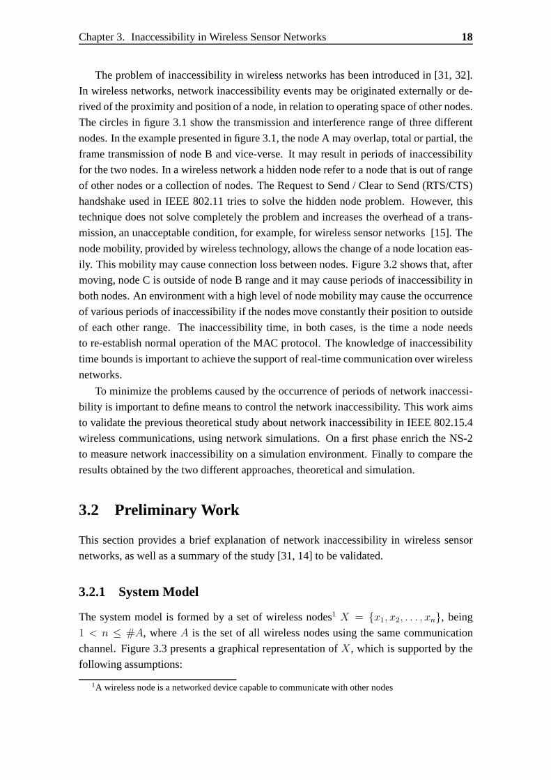
The problem of inaccessibility in wireless networks has been introduced in [31, 32].
In wireless networks, network inaccessibility events may be originated externally or de-
rived of the proximity and position of a node, in relation to operating space of other nodes.
The circles in figure 3.1 show the transmission and interference range of three different
nodes. In the example presented in figure 3.1, the node A may overlap, total or partial, the
frame transmission of node B and vice-verse. It may result inperiods of inaccessibility
for the two nodes. In a wireless network a hidden node refer toa node that is out of range
of other nodes or a collection of nodes. The Request to Send / Clear to Send (RTS/CTS)
handshake used in IEEE 802.11 tries to solve the hidden node problem. However, this
technique does not solve completely the problem and increases the overhead of a trans-
mission, an unacceptable condition, for example, for wireless sensor networks [15]. The
node mobility, provided by wireless technology, allows thechange of a node location eas-
ily. This mobility may cause connection loss between nodes.Figure 3.2 shows that, after
moving, node C is outside of node B range and it may cause periods of inaccessibility in
both nodes. An environment with a high level of node mobilitymay cause the occurrence
of various periods of inaccessibility if the nodes move constantly their position to outside
of each other range. The inaccessibility time, in both cases, is the time a node needs
to re-establish normal operation of the MAC protocol. The knowledge of inaccessibility
time bounds is important to achieve the support of real-timecommunication over wireless
networks.
To minimize the problems caused by the occurrence of periodsof network inaccessi-
bility is important to define means to control the network inaccessibility. This work aims
to validate the previous theoretical study about network inaccessibility in IEEE 802.15.4
wireless communications, using network simulations. On a first phase enrich the NS-2
to measure network inaccessibility on a simulation environment. Finally to compare the
results obtained by the two different approaches, theoretical and simulation.
3.2 Preliminary Work
This section provides a brief explanation of network inaccessibility in wireless sensor
networks, as well as a summary of the study [31, 14] to be validated.
3.2.1 System Model
The system model is formed by a set of wireless nodes1 X = {x1, x2, . . . , xn}, being
1 < n ≤ #A, whereA is the set of all wireless nodes using the same communication
channel. Figure 3.3 presents a graphical representation ofX, which is supported by the
following assumptions:
1A wireless node is a networked device capable to communicatewith other nodes

Chapter 3. Inaccessibility in Wireless Sensor Networks 19
Figure 3.3: The graphical representation of a wireless network segment.
1. The communication range ofX, i.e. its broadcast domain, is given by:BX =n⋂
j=1BD(x), ∀x ∈ X, whereBD(x) represents the communication range of a node
x;
2. ∀x ∈ A, x ∈ X ⇐⇒ BD(x)⋂
BX = BX or, as a consequence of node mobility,
x /∈ X ⇐⇒ BD(x)⋂
BX 6= BX ;
3. ∀x ∈ X can sense the transmissions of one another;
4. ∃x ∈ X which is the coordinator, being unique and with responsibility to manage
the set;
5. A network component either behaves correctly or crashes upon exceeding a given
number of consecutive omissions (the component’somission degree, fo) in a time
interval of reference2, Trd;
6. failure bursts never affect more thanfo transmissions in a time interval of reference,
Trd;
7. omission failures may be inconsistent (i.e., not observed by all recipients).
The setX itself represents a network entity dubbed Wireless networkSegment (WnS),
as depicted in Figure 3.3. For a given WnS, assumptions1, 2, and3 define the physical
relationship between nodes, assumption4 defines the existence of a coordinator, and as-
sumptions5, 6, and7 define how communication errors within the WnS are handled. All
communications and relations between nodes are established at MAC level, which are
reinforced by assumption3. As a consequence of mobility, nodes may be driven away of
a given WnS (assumption2). All communication errors within WnS are transformed into
2For instance, the duration of a given protocol execution. Note that this assumption is concerned withthe total number of failures of possibly different nodes.

Chapter 3. Inaccessibility in Wireless Sensor Networks 20
omissions (assumption5), and in the context of network components an omission is an
error that destroys a data or control frame.
3.2.2 Network inaccessibility
There are two different types of frames that can be affected by the occurrence of distur-
bances on the normal network operation, control and data frames. The first one is used to
manage and sustain the network operational. Whenever the control frame transmissions
are corrupted with errors, the MAC layer has to execute actions in order to maintain the
network operation after the occurrence of these errors. This is called a period of network
inaccessibility, which is the time interval between the moment that the errors mentioned
above occurs, and the normal network operation is restored.A node, during the referred
period, is unable to access the network, and cannot communicate with other nodes. Due
to this a temporary blackout on the network communication services occurs.
3.2.3 Theoretical modeling of network inaccessibility in IEEE 802.15.4
In Table 3.1 we present a collection of easy-to-use formulasdefining the durations of
periods of network inaccessibility. The worst case duration, (represented by the super-
scriptwc, presented for each network inaccessibility scenario. Thedifferent parameters
used in the formulas of Table 3.1 are as follows:nrchannels, represents the number
of channels to be scanned;nrWait, defines the waiting period for a beacon frame in
each channel scan, assuming the default value ofnrWait = 32 in the IEEE 802.15.4
standard;TMAC ack(frame) andTMAC ack(frame) represent the delay from request to
confirmation of a MAC frame transmission time with and without acknowledgement,
respectively;TMLA(action) represents the time needed to perform the specified action
at the MAC management sublayer. Without loss of generality,an uniform value of
TMLA(action) = TBI/10 is assumed for the duration of each MAC management sub-
layer action.
For the relevant scenarios, we describe next how the corresponding periods of network
inaccessibility are obtained. The beacon frame controls the access to the network, and its
reception is essential to maintain all the nodes synchronized within the different periods
of the superframe structure. If a beacon frame is not correctly received an inaccessibility
incident occurs. Thus, abeacon frame lossoccurs when only one beacon is lost. The
value of this period of inaccessibility isTBI plus oneTBSD period, which is utilized as a
margin to overcome some clock deviations that may occur between nodes.
Themultiple beacon frame lossoccurs when multiple and consecutive beacons are
lost and a correct beacon frame is successfully received after the loss ofnrLost beacons.
The synchronization lossis a special case of the multiple beacon frame loss scenario
where after the loss ofnrLost beacons the next beacon is also lost.

Chapter 3. Inaccessibility in Wireless Sensor Networks 21
Scenario Equation
Single Bea-con FrameLoss
Twcina←sbfl
= TBSD . (2BO + 1)
MultipleBeaconFrame Loss
Twcina←mbfl
= TBSD .
(
2BO + 1)
. nrLost
SynchronizationLoss
Tina←nosync = TBSD .
(
2BO + 1)
. nrLost
OrphanNode
Twcina←orphan
= Tina←nosync + TMLA(Orphan)
+
nrchannels∑
j=1
(
TwcMAC
(Orphan) + nrWait . TBSD
)
+ TwcMAC ack
(Realign)
CoordinatingOrphan Re-alignment
Twcina←realign
= TMLA(Realign) + TwcMAC ack
(Realign)
CoordinatorConflictDetection
Twcina←C Detection
= TwcMAC ack
(C Conflict)
CoordinatorConflictResolution
Twcina←C Resolution
= TMLA(Conflict) +
nrchannels∑
j=1
[
TwcMAC
(Beacon R)+nrWait.TBSD
]
+TMLA(Realign) + TwcMAC
(Realign)
Extract Re-quest
Twcina←extReq
= TwcMACack
(ExtReq) + Twait
GTS re-quest
Twcina←GTS
= TwcMAC ack
(GTS)
Association Twcina←assoc
=
nrchannels∑
j=1
[
TwcMAC
(Beacon R) + nrWait.TBSD
]
+ TMLA(Beacon) + Twcina←extReq
+
TMLA(AssocReq) + TwcMAC ack
(AssocReq)
Re-Association
Twcina←reAssoc
= Tina←nosync + Twcina←assoc
Table 3.1: Easy-to-use formulas defining the durations of periods of network inaccessi-bility
To recover from such loss of synchronization two different strategies were identified
in the standard specification [11]. Each individual node chooses the recovery strategy
to be used. If some data/control frame was received during the last beacon interval, the
node assumes anorphan status; otherwise, are-associationprocedure should be carried
out. In both recovery strategies, the node looks for a coordinator in the given set of chan-
nels. After the channel scan, acoordinator realignment or a re-associationprocedure
is performed within theorphan andre-associationscenarios, respectively.
In the execution of theassociationprocedure, the channel scan is followed by a bea-
con processing action, the extract of control information,an association processing ac-
tion and the actual association with the coordinator. There-associationandassociationprocedures are quite equivalent. Theassociationprocedure is executed when a non-
coordinator node has no information about its coordinator.
A coordinator conflict occurs when more than one coordinator is active within the
same network. By default, each network has a unique identifier, networkID, which
identifies the network uniquely and is used by the coordinator in beacon transmissions.
If some other (possibly old) coordinator enters the broadcast domain, e.g., after mov-
ing away during a long period of time, the network may have twodifferent coordinators
transmitting beacons with the samenetworkID. To solve such conflict, the actual coor-
dinator performs a search within a set of specified channels.If the coordinator does not

Chapter 3. Inaccessibility in Wireless Sensor Networks 22
found other coordinator sending beacons with its own identifier after the scan in all chan-
nels, no further action is taken and the network becomes accessible again. Otherwise, a
new identifier is selected and, if necessary, a MAC coordinator realignment command is
broadcast. In table 3.1, this scenario is separated in two individual contributions:coor-dinator conflict detection, to be performed upon the detection of a coordinator conflict
and its notification; a longercoordinator conflict resolution procedure, which includes
the channel search procedure.
The final scenarios do include the procedure required for requesting the allocation of
a GTS slot and the procedure to extract control information from the coordinator. Time-
liness and dependability properties of the network may be compromised by the conse-
quence of network inaccessibility. The existent simulation tools should be enhanced to
include mechanisms capable to test MAC sublayer operation under error conditions, pro-
viding then accurate analysis regarding the temporal aspects of the network.
3.3 Summary
In this chapter we presented an overview of a previous theoretical study [31] that shows
that errors affecting MAC sublayer management operations may lead occurrence of ”black-
outs“ within IEEE 802.15.4 wireless communications, wherethe network remains inac-
cessible by a temporary period of time. This period is dubbednetwork inaccessibility,
and its characterization involves the detailed study of thecorresponding MAC protocol
operation. A comprehensive set of scenarios leading to network inaccessibility is thor-
oughly discussed. Network inaccessibility has a strong negative impact in the temporal
behaviour of IEEE 802.15.4 networks, being extremely important its characterization.
Chapter 4
Improving the IEEE 802.15.4 NS-2simulation module for real-timeoperation
4.1 Problem Definition
The original NS-2 simulator IEEE 802.15.4 module is not fully compliant with the stan-
dard, regarding the behaviour and support of transmissionswith real-time requirements.
Although NS-2 is extensively used in wireless sensor network simulations with ex-
tended libraries, from our analysis, we discovered severalaspects of NS-2 operation that
need to be improved to secure the provisioning analysis workof real-time guarantees.
These improvements are two fold: developing IEEE 802.15.4 standard management oper-
ations not implemented in the official NS-2 release; Implementing the absent mechanisms
such as the communication in CFP.
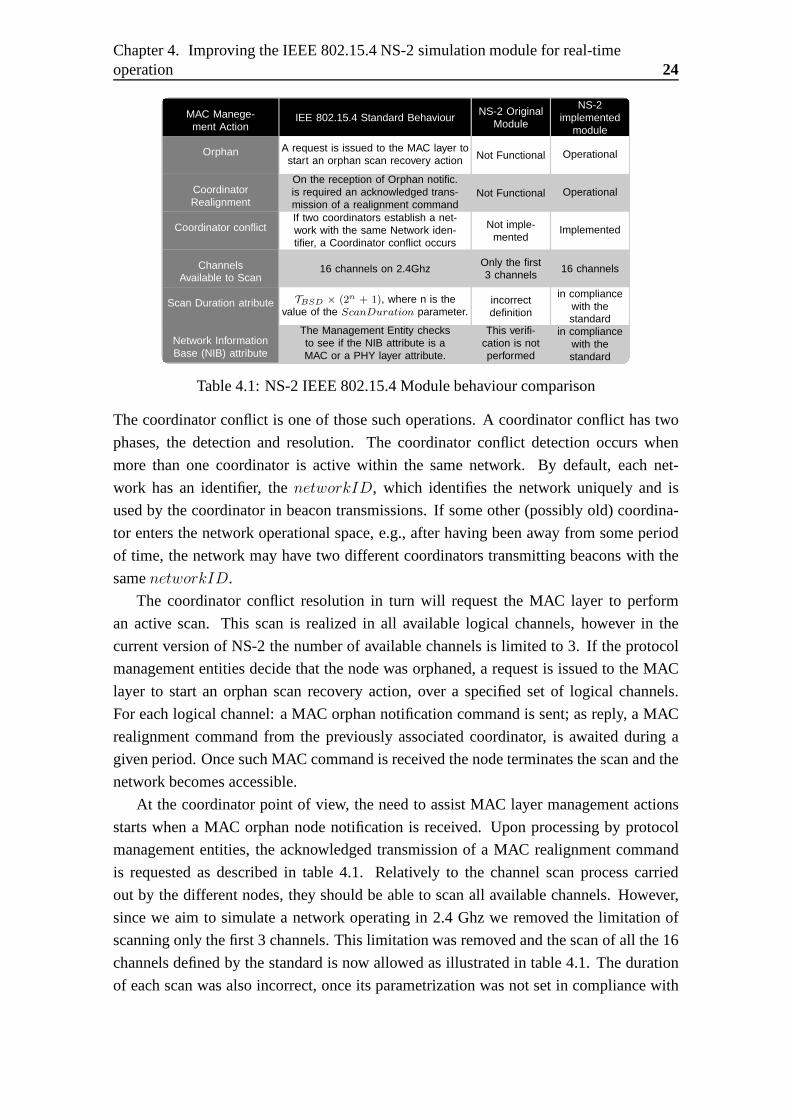
4.2 Incorporating and enhancing MAC Management ac-tions according to the Standard
The NS-2 simulator module has some differences in the behaviour regarding the imple-
mentation of IEEE 802.15.4 standard MAC management actions. Taking this in consider-
ation we added the functions presented in table 4.1. Some operations are implemented in
the original module but they are not fully functional. We corrected them and implemented
other additional operations, as needed.
23
Chapter 4. Improving the IEEE 802.15.4 NS-2 simulation module for real-timeoperation 24
MAC Manege-ment Action
IEE 802.15.4 Standard BehaviourNS-2 Original
Module
NS-2implemented
module
Orphan A request is issued to the MAC layer tostart an orphan scan recovery action Not Functional Operational
CoordinatorRealignment
On the reception of Orphan notific.is required an acknowledged trans-mission of a realignment command
Not Functional Operational
Coordinator conflictIf two coordinators establish a net-work with the same Network iden-tifier, a Coordinator conflict occurs
Not imple-mented
Implemented
ChannelsAvailable to Scan
16 channels on 2.4GhzOnly the first3 channels
16 channels
Scan Duration atribute TBSD × (2n + 1), where n is thevalue of the ScanDuration parameter.
incorrectdefinition
in compliancewith thestandard
Network InformationBase (NIB) attribute
The Management Entity checksto see if the NIB attribute is aMAC or a PHY layer attribute.
This verifi-cation is notperformed
in compliancewith thestandard
Table 4.1: NS-2 IEEE 802.15.4 Module behaviour comparison
The coordinator conflict is one of those such operations. A coordinator conflict has two
phases, the detection and resolution. The coordinator conflict detection occurs when
more than one coordinator is active within the same network.By default, each net-
work has an identifier, thenetworkID, which identifies the network uniquely and is
used by the coordinator in beacon transmissions. If some other (possibly old) coordina-
tor enters the network operational space, e.g., after having been away from some period
of time, the network may have two different coordinators transmitting beacons with the
samenetworkID.
The coordinator conflict resolution in turn will request theMAC layer to perform
an active scan. This scan is realized in all available logical channels, however in the
current version of NS-2 the number of available channels is limited to 3. If the protocol
management entities decide that the node was orphaned, a request is issued to the MAC
layer to start an orphan scan recovery action, over a specified set of logical channels.
For each logical channel: a MAC orphan notification command is sent; as reply, a MAC
realignment command from the previously associated coordinator, is awaited during a
given period. Once such MAC command is received the node terminates the scan and the
network becomes accessible.
At the coordinator point of view, the need to assist MAC layermanagement actions
starts when a MAC orphan node notification is received. Upon processing by protocol
management entities, the acknowledged transmission of a MAC realignment command
is requested as described in table 4.1. Relatively to the channel scan process carried
out by the different nodes, they should be able to scan all available channels. However,
since we aim to simulate a network operating in 2.4 Ghz we removed the limitation of
scanning only the first 3 channels. This limitation was removed and the scan of all the 16
channels defined by the standard is now allowed as illustrated in table 4.1. The duration
of each scan was also incorrect, once its parametrization was not set in compliance with

Chapter 4. Improving the IEEE 802.15.4 NS-2 simulation module for real-timeoperation 25
the standard. Again, the issue was corrected, as inscribed in table 4.1
4.3 CFP and GTS implementation in NS-2
On IEEE 802.15.4 networks data can be transmitted in three ways: Direct transmission,
which means that data is sent during the CAP;Indirect transmission, which is only avail-
able for coordinators. The data is placed on the indirect transmission queue and is sent
during the CAP when polled. And finallyGTS transmission, which requires that a node
has to use a GTS slot to transmit its data. To allow this, a GTS slot is allocated to the node
for the specified data transmission. Although a data transmission request can occur at
Algorithm 1 Transmission Data Frame using GTS1: Begin.2: MAC.Data.Send.Request(data);3: whenallocated GTS is reacheddo4: MAC.Data.transmit(data);5: end when6: End.
any-time in a superframe, a data transmission request usinga GTS is required to transmit
the data only during the allocated GTS. Therefore, in our implementation described in
Algorithm:1, it is checked if the data transmission requestusing, represented on line 2, a
GTS is in the allocated GTS duration or not, as represent on line 3.
After a GTS allocation is checked at the beacon, a timer for the expiration is started
at the allocated GTS starting slot, and the data is transmitted during the allocated GTS
interval as represent on line 4. Since the procedure to checkthe remaining GTS time is
also implemented, multiple data can be transmitted during aGTS, which complies with
the IEEE 802.15.4 standard.
Algorithm 2 Coordinator processing a GTS request command1: Begin.2: MAC.Mgmt.GTS.Request(nodeaddr, nr slots);3: if nr slots are availablethen4: MAC.Mgmt.GTS.allocate(nodeaddr, nr slots);5: MAC.Mgmt.GTS.updateGTSList(nodeaddr);6: else7: MAC.Mgmt.GTS.Response(slots not available);8: end if9: End.
When a coordinator receives a GTS request command from a nodewilling to transmit
data, Algorithm:2 is executed by the coordinator. After checking if the node GTS slot is
valid (line 3), which means thenodeaddr is already known by the coordinator andnr slots
are available, the allocation is made (line 4).

Chapter 4. Improving the IEEE 802.15.4 NS-2 simulation module for real-timeoperation 26
If the operation is successfully concluded, the final CAP slot subfield of the super-
frame specification field of the beacon frame is updated as in line 5, and the updated
beacon is sent. If all the GTS slots are occupied at the time, an information regarding
slots not available is sent to the node, as described in line 7. The information from the
GTS allocation or deallocation is delivered in the next beacon frame to the nodes that sent
the GTS request command, letting them know the result of the requesting process.
4.4 Design and implementation of the solution
In order to achieve a better real-time support from the IEEE 802.15.4 simulation mod-
ule, we extend the existent module to provide the GTS mechanism for network nodes.
The adaptation was made changing some main classes of the IEEE 802.15.4 module, as
represented in figure 4.1.
In the p80215 4mac class, the entity that represents the MAC layer, existsa variable
txOption which corresponds to the transmission options of the IEEE 802.15.4 standard.
This is defined as a static variable and is responsible for defining the options of data
transmission. This implies that every node in the simulation environment deliver data
using the same transmission options. This was modified allowing each node decide if
want to transmit during CFP or CAP. Also a new timer was developed in order to control
the expiration of an allocated GTS slot.
The GTS related methods that were provided in form of declaration but not imple-
mented in the native version of the IEEE 802.15.4 module werealso added both in the
class p80215 4mac class and p80215 4sscs, which represent the connection between
the MAC and the LLC layer and provides a way to access all the MAC primitives. The
p80215 4sscs interface is modified so that the GTS bit of thetxOption can be set or
reset in the Tcl file. By doing so, it is possible for a specifiednode to be selected to use a
GTS, and even a GTS can be controlled to be used or not by setting or resetting the GTS
transmission bit.
Even though some structs for the GTS field exist and their simple implementations
are available in p80215 4field class, these do not suffice for communication using the
GTS. Such examples include the final CAP slot input field of thesuperframe specification
used at the time of the beacon frame generation and the use of the GTS in the MCPS-
DATA.request primitive used at the time of the data frame transmission.
So on the p80215 4field class, auxiliary methods had to be implemented, to support
the management of the GTS allocation/deallocation mechanisms. However the adaptation
of the CFP implementation in [5], to the latest version of thesimulator used in this study,
revealed some issues and incompatibilities.
The referenced implementation proposed in [5] prevents theuse of MAC management
commands such as Orphan Notification and Coordinator Realignment. In our implemen-

Chapter 4. Improving the IEEE 802.15.4 NS-2 simulation module for real-timeoperation 27
Figure 4.1: Class diagram of changed classes on native IEEE 802.15.4 module
tation this was corrected and the GTS can be activated from the NS-2 script without
affecting other MAC services.
4.5 Data Analysis
In order to better understand the results of our simulationswe developed some reporting
tools, capable of summarize the important events that occur.
A performance report tool was also developed after defining some evaluation metrics
described on the section 4.6. The tool was made through anAWK script that produces a
report analysis regarding the defined metrics.AWK uses a data-driven scripting language
consisting of a set of actions to be taken against textual data (either in files or data streams)
for the purpose of producing formatted reports. Our script takes the NS-2 simulation log
file as an input, and produce multiple text files with information about throughput, end-to-
end delay, energy consumption, MAC control frames exchanged, traffic load and packet
delivery ratio.
The NS-2 simulation log files are also used to generate a graphical analysis through a
gnuplotscript, giving a better knowledge of the events observed during simulations.
4.6 Evaluation metrics for an effective real-time commu-nication in Wireless Sensor Networks
Several metrics can be defined to grade the performance of a technology against the ele-
ments of wireless networking. These metrics have been carefully chosen to demonstrate

Chapter 4. Improving the IEEE 802.15.4 NS-2 simulation module for real-timeoperation 28
the performance and the timeliness of the IEEE 802.15.4 networks. A detailed explana-
tion of these metrics follows:
• Data Frame Delivery Ratio (DFDR), which is the ratio between the total number
of frames received in MAC sub-layer and the total number of data frame transmit
requests during the simulation period. In our simulation weconsider the data frames
transmit requests issued by all the nodes but the coordinator.
DFDR =Total Data frames received× 100
Total Data frames transmit requests(4.1)
• Latency, which represents the transfer time of a data frame to a one-hop neighbour.
For each individual data frame transfer, the frame transferlatency represents the
interval between the instant when the data frame transmit request is issued(T tx-
Data) and the instant of the corresponding data frame reception(TrxData). This
metric includes the data frame processing and queueing timeat the nodes, the data
frame transmission time and the back off interval (if applicable). The average la-
tency can then be calculated over all successful end-to-endtransmissions within the
simulation run.
AverageLatency =
∑
allreceivedframes(TrxData− T txData)
Total number of received frames(4.2)
On the other hand, the worst case value is given by:
WorstCaseLatency = maxallreceivedframes
(TrxData− T txData) (4.3)
• Energy, the energy model present in NS-2 is used to calculate the amount of energy
consumed by the nodes during the simulation time.
Energy Used per Node =Total Energy Used
Number of Nodes(4.4)
• Throughput, it measures the amount of data successfully received by thedestination
node within certain period of time.
Throughput =packets received × packet size
Simulation T ime(4.5)
4.7 NS-2 Network Simulation Results
In this section we address a performance evaluation on different characteristics of IEEE
802.15.4 wireless networks. A comprehensive set of scenarios regarding the evaluation
metrics, for an effective real-time communication, is thoroughly discussed.

Chapter 4. Improving the IEEE 802.15.4 NS-2 simulation module for real-timeoperation 29
Simulation ParametersNS-2 Version 2.35 updated with GTS featuresNetwork Topology Star TopologyNodes 7Traffic Constant Bit Rate (CBR)Reception range 15mCarrier Sense range 15mPacket Size 70 bytesCAP Transmission Type Direct, using CSMA/CACFP Transmission Type GTS transmissionTransmission/Reception Power30mWBeacon EnabledBeacon Order 3Superframe Order 3Maximum CSMA/CA Attempts 4Simulation Time 600 seconds
Table 4.2: Simulation Parameters
4.7.1 Simulation Setup
To evaluate our implementation, the simulations conductedin NS-2 will be analysed. First
the appropriate evaluation metrics for an effective real-time communication in WSNs and
WSANs are addressed in 4.6. Then is described the simulationset-up and finally the
results achieved. Furthermore, all values were calculatedand obtained based on a 2.4GHz
IEEE 802.15.4 frequency operation.
The star topology network was chosen in this simulation. Thenetwork was simulated
with seven nodes, where one of these nodes, in the center, wasthe coordinator. All other
nodes are in the radio transmission range of the coordinator. Additionally all nodes are
in a single broadcast domain, which means that all the nodes are within the range of each
other. The simulation parameters are described in table 4.2.
To evaluate the network behaviour, the six remaining nodes constantly transmit data
frames to the coordinator during CAP or CFP. The traffic generator is set to produce Con-
stant Bit Rate traffic (CBR), which means data frames are transmitted at a constant rate
from the nodes to the coordinator. The interval between eachdata transmission request
is successively set to 1, 0.1, 0.01 and 0.001 seconds. Given the packet size of 70 bytes,
this means the network load is monotonically increased, adopting the values of 0.07, 0.7,
7 and 70 KB/s. The MAC management actions required for node association with its
coordinator and the GTS allocation times (if required) are excluded from the evaluation
scope in the present simulation run.

Chapter 4. Improving the IEEE 802.15.4 NS-2 simulation module for real-timeoperation 30
4.7.2 Simulation Results
0
20
40
60
80
100
10 20 30 40 50 60 70 80 90 100
Dat
a F
ram
e D
eliv
ery
Rat
io (
%)
Network Load (KB/s)
Data Frame Delivery Ratio comparison (CFP vs CAP)
CFPCAP
Figure 4.2: Data Frame Delivery Ratio comparison between transmission during CAPand CFP
Figure 4.2 represents the delivery ratio on the network, providing a comparison of the
results achieved for transmission requests issued during the CAP and CFP periods. During
CFP, nodes use the allocated GTS and get direct and exclusivenetwork access, which
allows to achieve about 100% delivery rate. In CAP the delivery ratio drops in function of
the increase in the network load. This is explained by the occurrence of collisions during
CAP, or due to the number of nodes attempting to access the medium. In the CSMA/CA
protocol a data frame transmit request is dropped, if the number of transmission attempts
exceed a given threshold defined by the Maximum CSMA/CA attempts (Table 4.2). This
value represents the maximum number of backoffs the CSMA/CAalgorithm will attempt
before declaring a channel access failure.
0.002
0.004
0.006
0.008
0.01
0.012
10 20 30 40 50 60 70 80 90 100
Late
ncy
(sec
onds
)
Network Load (KB/s)
Data Frame Transmission Latency comparison (CFP vs CAP)
CFP averageCAP average
CFP Worst CaseCAP Worst Case
Figure 4.3: Data frame transmission Latency comparison between transmission duringCAP and CFP

Chapter 4. Improving the IEEE 802.15.4 NS-2 simulation module for real-timeoperation 31
Figure 4.3 shows the latency comparison between a data frametransmission using
CFP and CAP. While the latency remains almost constant when data frames are trans-
mitted during CFP, using allocated GTS, the latency highly increases while using CAP.
The constancy achieved in data frame transfer times during CFP is a sign of determinism
and predictability and shows in figure 4.3 in two ways: an (almost) constant worst-case
data frame transmission latency; the optimal value of this latency, which does not exceed
0.002936 seconds. This is due to nodes during CFP get exclusive network access, mean-
ing nodes do not have to check if the media is idle and no collisions occur for those nodes.
These results show the importance of the GTS mechanism in applications with real-time
requirements on which deterministic data frame transmission times are mandatory. Addi-
tionally, the data frame transmission latency increases inCAP, up to the worst-case value
of 0.010512 seconds, given the worst-case network load in the simulation setup.
0.5
1
1.5
2
2.5
10 20 30 40 50 60 70 80 90 100
Ene
rgy
cons
umed
per
nod
e (J
)
Network Load (KB/s)
Energy consumption comparison (CFP vs CAP)
CFPCAP
Figure 4.4: Energy consumption per node for data transmission during CAP and CFP
Finally, figure 4.4 represents the average energy consumption by the nodes during the
simulation period. It worth noticing that the energy consumption increases when using
CFP in comparison with CAP as result of required beacon framereception tracking by
the node, an action that obliges the node to switch-on its transceiver during the active
period of every superframe instance. Contention-based access is more efficient under light
network loads, whereas contention-free access becomes preferable when the background
network load increases.
4.8 Summary
This chapter described improvements made to the IEEE 802.15.4 NS-2 simulator mod-
ule, in the course of this thesis work. We identified limitations, and the absence of vital
mechanisms required to support real-time simulations on WSN.
Therefore the support of NS-2 simulator to the IEEE 802.15.4was enhanced with
Chapter 4. Improving the IEEE 802.15.4 NS-2 simulation module for real-timeoperation 32
addition of GTS mechanism and the unimplemented MAC management functions such
as Coordinator Conflict, Orphan Node, Coordinator realignment.
Based on NS-2 simulations, we evaluate the performance of various features in the
IEEE 802.15.4 MAC. We find that data transmission during the CAP reduces energy
cost due to idle listening in the backoff period but increases the collision at higher rate
and larger number of sources. While the use of GTS in the CFP can allow dedicated
bandwidth to a device to ensure low latency, the device need to track the beacon frames
in this mode, which increases the energy cost. The addition of available channels to scan
during association revealed an increase of the associationtime an energy cost, but made
the NS-2 more compliant to the standard.
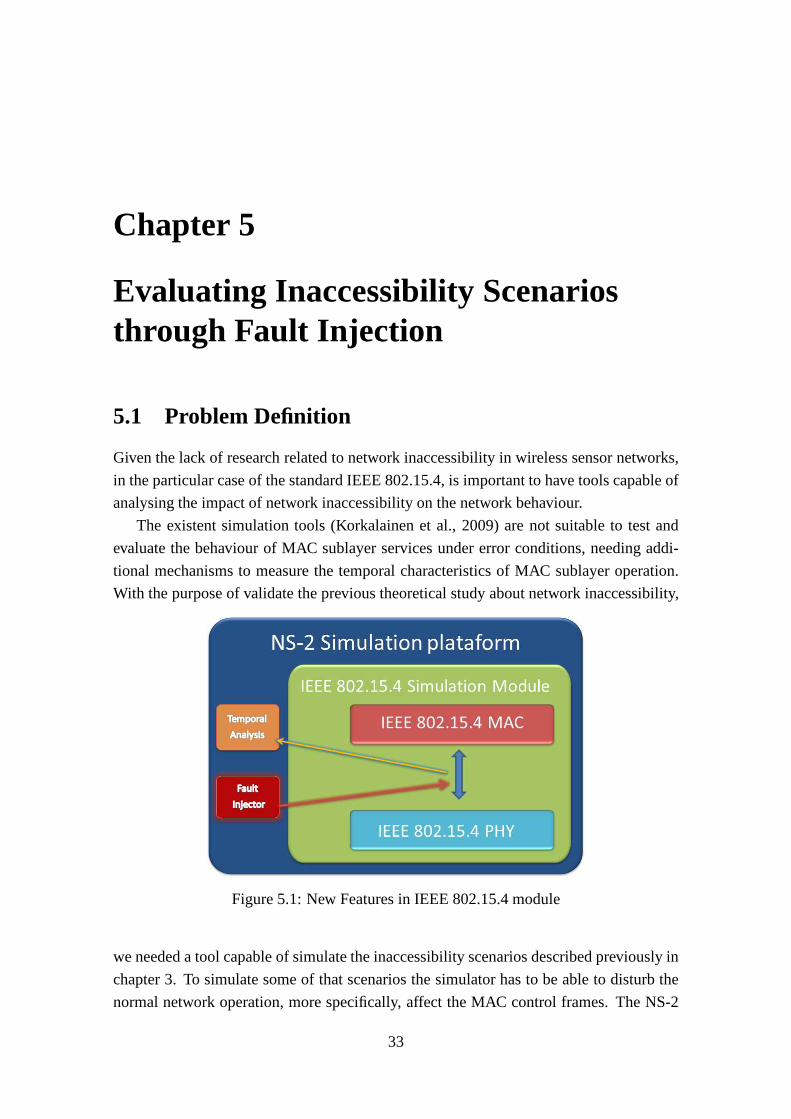
Chapter 5
Evaluating Inaccessibility Scenariosthrough Fault Injection
5.1 Problem Definition
Given the lack of research related to network inaccessibility in wireless sensor networks,
in the particular case of the standard IEEE 802.15.4, is important to have tools capable of
analysing the impact of network inaccessibility on the network behaviour.
The existent simulation tools (Korkalainen et al., 2009) are not suitable to test and
evaluate the behaviour of MAC sublayer services under errorconditions, needing addi-
tional mechanisms to measure the temporal characteristicsof MAC sublayer operation.
With the purpose of validate the previous theoretical studyabout network inaccessibility,
Figure 5.1: New Features in IEEE 802.15.4 module
we needed a tool capable of simulate the inaccessibility scenarios described previously in
chapter 3. To simulate some of that scenarios the simulator has to be able to disturb the
normal network operation, more specifically, affect the MACcontrol frames. The NS-2
33

Chapter 5. Evaluating Inaccessibility Scenarios through Fault Injection 34
already provides an error model, however this model cannot affect a specific frame such
as MAC control frame. To overcame the current error model limitation, we complement
the existing NS-2 components with the integration of new features, fault injector and tem-
poral analysis, in the NS-2 but separated from IEEE 802.15.4module, as represented in
the figure 5.1.
5.2 Injecting faults to simulate accidental errors on thenetwork operation
Our fault injector is capable to use a fault pattern to injecterrors during the simulation.
The criteria to define the fault pattern is totally configurable, allowing the definition of
deterministic or probabilistic fault patterns. A illustration of the fault injection scheme is
shown in the figure 5.2.
Figure 5.2: Fault Injector scheme
As an example from the faults that can be injected, illustrated in the figure 5.2, a fault
pattern can be defined to provoke transmission errors randomly in time (random noise or
interference) or be localized in specific time intervals (deterministic noise). On both of
these patterns, the fault injector can be customized regarding the type of frame to affect,
the rate and the duration of the fault injection.
Patterns with long duration are discouraged for deterministic error models, since such
long duration may cause a permanent inaccessibility to the network access if the affected
frame is MAC control frame. For example, if we are corruptinga beacon frame injecting
deterministic faults successively over a long period we maycause the loss of synchro-
nization by the node and consequently this becoming unable to access the network again.
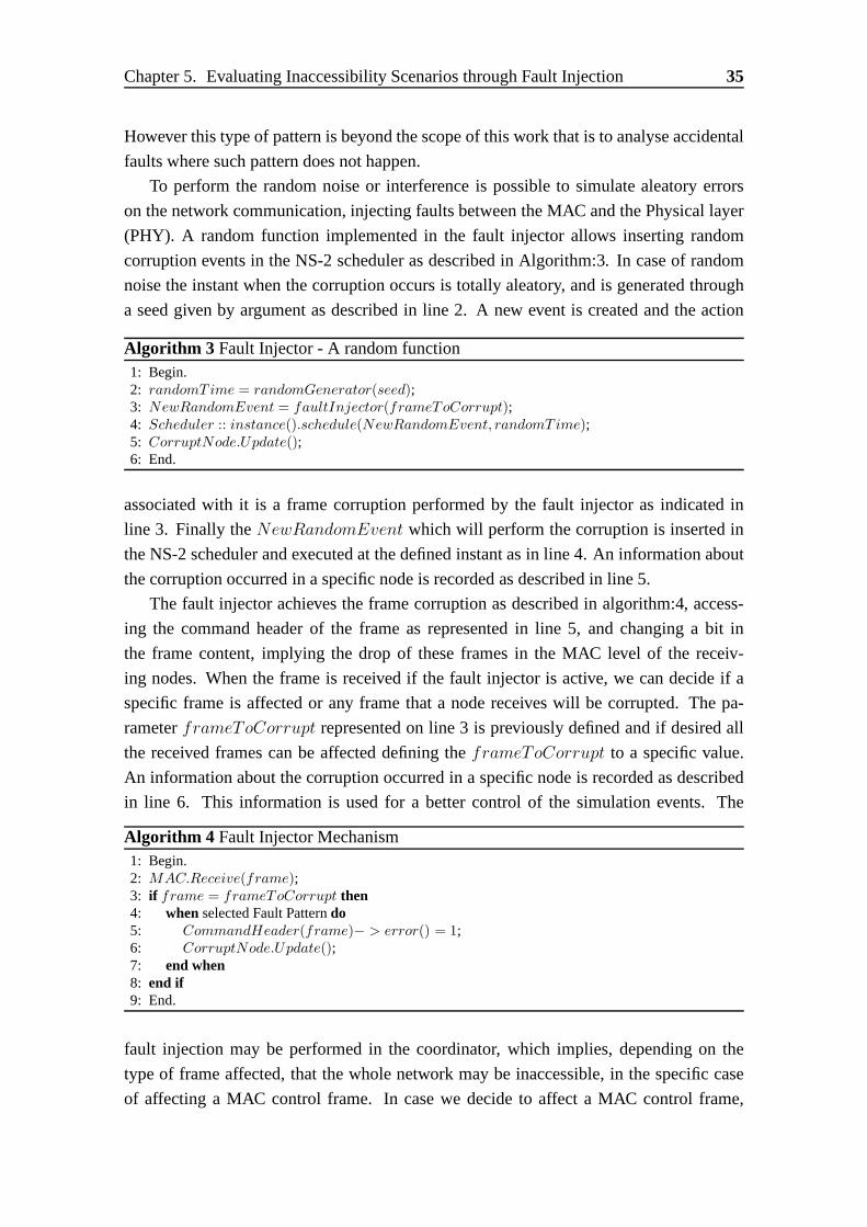
Chapter 5. Evaluating Inaccessibility Scenarios through Fault Injection 35
However this type of pattern is beyond the scope of this work that is to analyse accidental
faults where such pattern does not happen.
To perform the random noise or interference is possible to simulate aleatory errors
on the network communication, injecting faults between theMAC and the Physical layer
(PHY). A random function implemented in the fault injector allows inserting random
corruption events in the NS-2 scheduler as described in Algorithm:3. In case of random
noise the instant when the corruption occurs is totally aleatory, and is generated through
a seed given by argument as described in line 2. A new event is created and the action
Algorithm 3 Fault Injector - A random function1: Begin.2: randomT ime = randomGenerator(seed);3: NewRandomEvent = faultInjector(frameToCorrupt);4: Scheduler :: instance().schedule(NewRandomEvent, randomT ime);5: CorruptNode.Update();6: End.
associated with it is a frame corruption performed by the fault injector as indicated in
line 3. Finally theNewRandomEvent which will perform the corruption is inserted in
the NS-2 scheduler and executed at the defined instant as in line 4. An information about
the corruption occurred in a specific node is recorded as described in line 5.
The fault injector achieves the frame corruption as described in algorithm:4, access-
ing the command header of the frame as represented in line 5, and changing a bit in
the frame content, implying the drop of these frames in the MAC level of the receiv-
ing nodes. When the frame is received if the fault injector isactive, we can decide if a
specific frame is affected or any frame that a node receives will be corrupted. The pa-
rameterframeToCorrupt represented on line 3 is previously defined and if desired all
the received frames can be affected defining theframeToCorrupt to a specific value.
An information about the corruption occurred in a specific node is recorded as described
in line 6. This information is used for a better control of thesimulation events. The
Algorithm 4 Fault Injector Mechanism1: Begin.2: MAC.Receive(frame);3: if frame = frameToCorrupt then4: whenselected Fault Patterndo5: CommandHeader(frame)− > error() = 1;6: CorruptNode.Update();7: end when8: end if9: End.
fault injection may be performed in the coordinator, which implies, depending on the
type of frame affected, that the whole network may be inaccessible, in the specific case
of affecting a MAC control frame. In case we decide to affect aMAC control frame,
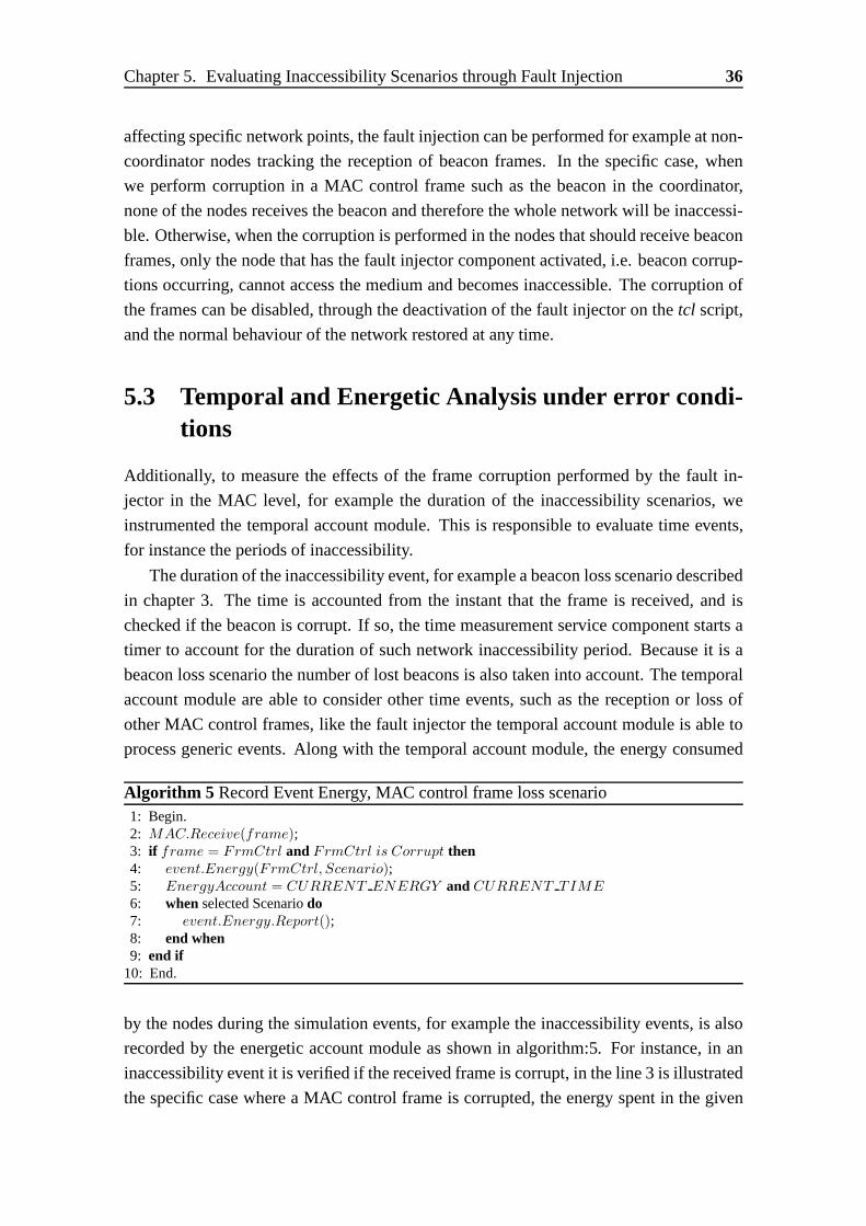
Chapter 5. Evaluating Inaccessibility Scenarios through Fault Injection 36
affecting specific network points, the fault injection can be performed for example at non-
coordinator nodes tracking the reception of beacon frames.In the specific case, when
we perform corruption in a MAC control frame such as the beacon in the coordinator,
none of the nodes receives the beacon and therefore the wholenetwork will be inaccessi-
ble. Otherwise, when the corruption is performed in the nodes that should receive beacon
frames, only the node that has the fault injector component activated, i.e. beacon corrup-
tions occurring, cannot access the medium and becomes inaccessible. The corruption of
the frames can be disabled, through the deactivation of the fault injector on thetcl script,
and the normal behaviour of the network restored at any time.
5.3 Temporal and Energetic Analysis under error condi-tions
Additionally, to measure the effects of the frame corruption performed by the fault in-
jector in the MAC level, for example the duration of the inaccessibility scenarios, we
instrumented the temporal account module. This is responsible to evaluate time events,
for instance the periods of inaccessibility.
The duration of the inaccessibility event, for example a beacon loss scenario described
in chapter 3. The time is accounted from the instant that the frame is received, and is
checked if the beacon is corrupt. If so, the time measurementservice component starts a
timer to account for the duration of such network inaccessibility period. Because it is a
beacon loss scenario the number of lost beacons is also takeninto account. The temporal
account module are able to consider other time events, such as the reception or loss of
other MAC control frames, like the fault injector the temporal account module is able to
process generic events. Along with the temporal account module, the energy consumed
Algorithm 5 Record Event Energy, MAC control frame loss scenario1: Begin.2: MAC.Receive(frame);3: if frame = FrmCtrl andFrmCtrl is Corrupt then4: event.Energy(FrmCtrl, Scenario);5: EnergyAccount = CURRENT ENERGY andCURRENT TIME
6: whenselected Scenariodo7: event.Energy.Report();8: end when9: end if
10: End.
by the nodes during the simulation events, for example the inaccessibility events, is also
recorded by the energetic account module as shown in algorithm:5. For instance, in an
inaccessibility event it is verified if the received frame iscorrupt, in the line 3 is illustrated
the specific case where a MAC control frame is corrupted, the energy spent in the given
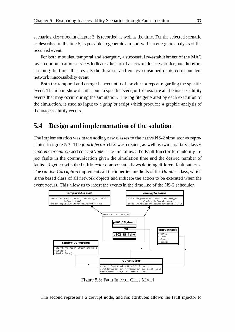
Chapter 5. Evaluating Inaccessibility Scenarios through Fault Injection 37
scenarios, described in chapter 3, is recorded as well as thetime. For the selected scenario
as described in the line 6, is possible to generate a report with an energetic analysis of the
occurred event.
For both modules, temporal and energetic, a successful re-establishment of the MAC
layer communication services indicates the end of a networkinaccessibility, and therefore
stopping the timer that reveals the duration and energy consumed of its correspondent
network inaccessibility event.
Both the temporal and energetic account tool, produce a report regarding the specific
event. The report show details about a specific event, or for instance all the inaccessibility
events that may occur during the simulation. The log file generated by each execution of
the simulation, is used as input to agnuplotscript which produces a graphic analysis of
the inaccessibility events.
5.4 Design and implementation of the solution
The implementation was made adding new classes to the nativeNS-2 simulator as repre-
sented in figure 5.3. ThefaultInjectorclass was created, as well as two auxiliary classes
randomCorruptionandcorruptNode. The first allows the Fault Injector to randomly in-
ject faults in the communication given the simulation time and the desired number of
faults. Together with the faultInjector component, allowsdefining different fault patterns.
TherandomCorruptionimplements all the inherited methods of theHandlerclass, which
is the based class of all network objects and indicate the action to be executed when the
event occurs. This allow us to insert the events in the time line of the NS-2 scheduler.
Figure 5.3: Fault Injector Class Model
The second represents a corrupt node, and his attributes allows the fault injector to

Chapter 5. Evaluating Inaccessibility Scenarios through Fault Injection 38
control the current execution. Providing information about the current affected node, how
much time it has been corrupted and the type of frame that is being affected in the current
simulation.
Two other classes were developed to support the analysis of the simulation events,
thetemporalAccountwhich for example, records the duration of the inaccessibility events
and was developed using the internal timer class of the simulator. And theenergyAccount
which provides information about the energy spent during such events and was developed
using the current energy model of the simulator.
5.5 Simulating Inaccessibility Scenarios
In order to simulate the network inaccessibility scenariosdescribed in chapter 3, we con-
figure our fault injector component to generate deterministic faults. Starting with the
corruption of beacon frames and consequently the loss of beacons. Thus, a know number
of beacons is corrupted after the association of all nodes with coordinator, causing the
occurrence of the inaccessibility scenarios. The simulation is defined in an OTcl script
(Listing:5.1) and is carried out in an one-hop star topology, where all the nodes are within
the range of each other.
1 Event a t 0 . 0 node( 0 ) s t a r t W n S C o o r d i n a t o r $beaconOrder$superFrameOrder ” ;
2 Event a t 20 . 0 node( 1 ) & node ( 2 ) s t a r t D e v i c e ”3 Event a t 20 . 0 node( 1 ) enab leTempora lAccoun t $ S c e n a r i o ” ;4 Event a t 30 . 0 node( 0 ) s t a r t B e a c o n T r a n s m i s s i o n $beaconOrder
$superFrameOrder ”5 Event a t 30 . 0 node( 1 ) GTS On”6 Event a t 30 . 0 node( 1 ) S t a r t F a u l t I n j e c t i o n $Beacon $Rounds”7 Event a t $stopTime ” s t o p ”
Listing 5.1: NS-2 Simulation Script
In the script (Listing:5.1) we define that the first node to start was the coordinator, defining
hisBO andSO in line 1, then after the WnS is established we start the nodesin line 2. Our
temporal account module is enabled on line 3, given the selected scenario. The periodic
beacon transmission is initiated at the coordinator on line4, taking theBO andSO as
arguments. At line 5 we enable the GTS transmission for the node(1), which means that
hereinafter each time this node have data to transmit will use the GTS mechanism. Finally
at line 6 we start our fault injector to, in this example, corrupt beacon frames for a certain
number of rounds.
For each addressed scenario we set our fault injector to corrupt a specific frame at a
given number of times, on a chosen node. The fault injector can corrupt one of each frame
type present in the Table: 5.1 and described in section 2.1.1.

Chapter 5. Evaluating Inaccessibility Scenarios through Fault Injection 39
Frame type value Command frame ID Standard Reference
0 Beacon
1 Data
2 Ack
3 MAC Control Frame
01 Association Request
02 Association Response
03 Disassociation notification
04 Data Request
05 Coordinator conflict notification
06 Orphan notification
07 Beacon request
08 Coordinator realignment
09 GTS request
Table 5.1: MAC frame types
To achieve theSingle Beacon Frame Loss (SBFL)scenario we executed the following
schedule of Events:
1 Event a t 30 . 0 node( 1 ) S t a r t F a u l t I n j e c t i o n $Beacon $SBFL”
Which means the beacon frame will be corruptedSBFL number of times, corresponding
to the current scenario, at the Node(1) after the 30 simulations seconds.
TheMultiple Beacon Frame Loss (MBFL) happens when we change the number of
corrupting rounds on the fault injector depending on the value thatMBFL assumes in
order to achieve the loss ofnrLost beacons. Thesynchronization lossis a special case
of the MBFL scenario where after the loss ofnrLost beacons the next beacon is also lost.
1 Event a t 30 . 0 node( 1 ) S t a r t F a u l t I n j e c t i o n $Beacon $MBFL”
TheOrphan notification and Coordinator realignment are achieved when the fault
injector corruptsNOSY NC beacon frames, corresponding to the current scenario, and
the node lose the synchronization. The Orphan notification is observed on the node and
the Coordinator realignment is transmitted by the coordinator on response.
1 Event a t 30 . 0 node( 1 ) S t a r t F a u l t I n j e c t i o n $Beacon $NOSYNC”
So thatCoordinator Conflict Detection can occur, this event has to be forced on
the simulator. Once every time a node becomes a coordinator it assumes its ID as the
networkID, so a coordinator conflict is impossible because every coordinator assumes a

Chapter 5. Evaluating Inaccessibility Scenarios through Fault Injection 40
distinct ID. To force that event we oblige the coordinator touse the same identifier with
the following line.
1 Event a t 0 . 0 node( 1 ) C o o r d i n a t o r C o n f l i c t 1 ”2 Event a t 0 . 0 node( 0 ) C o o r d i n a t o r C o n f l i c t 1 ”
When theGTS mechanismis previously activated from the script, and the node has
data to transmit, a GTS Request will occur. This request willbe send to the coordinator
by the node to perform an allocation of a GTS slot for exclusive transmission time.
1 Event a t 30 . 0 node( 1 ) GTS On”
5.6 Inaccessibility Results
5.6.1 Simulation Setup
Regarding the Inaccessibility simulation environment, the simulation script (Listing:5.1)
was executed in order to achieve the duration of the inaccessibility scenarios. The network
was simulated with seven nodes, where one of these nodes, in the center, was the coordi-
nator. All other nodes are in the radio transmission range ofthe coordinator. Additionally
all nodes are in a single broadcast domain, which means that all the nodes are within the
range of each other. Our first set of simulation, address the inaccessibility scenarios, a
beacon orderBO = SO = 4 was utilized. The characteristics of the simulation setup
scenario are shown in Table 5.2.
Simulation ParametersNS-2 Version 2.35 updated with Fault Injector/
Temporal Analysis tool featuresNetwork Topology Star TopologyNodes 7Traffic Constant Bit Rate (CBR)Reception range 15mCarrier Sense range 15mPacket Size 70 bytesTransmission/Reception Power30mWBeacon EnabledBeacon Order 4Superframe Order 4Maximum CSMA/CA Attempts 4Simulation Time 600 seconds
Table 5.2: Simulation Parameters for Inaccessibility Scenarios with BO=SO=4

Chapter 5. Evaluating Inaccessibility Scenarios through Fault Injection 41
5.6.2 Simulation Results
After the environment setup, the simulation was performed to obtain the best and worst
case duration of the inaccessibility scenarios. Table 5.3 represents a comparison between
Inaccessibility Scenarios Comparison in s
Scenario Theoretical Best Theoretical Worst Simulated
Single Beacon Frame Loss 0.262 0.262 0.245
Multiple Beacon Frame Loss 0.262 1.045 0.737
Synchronization Loss 1.045 1.045 0.737
Orphan Node 1.099 9.527 8.148
Coordinator Realignment 0.028 0.150 0.017
GTS Request 0.002 0.120 0.001
Coordinator Conflict Detection 0.003 0.126 0.001
Coordinator Conflict Resolution 0.518 8.354 8.052
Association 0.522 8.605 7.717
Re-Association 1.567 9.649 8.270
Table 5.3: Theoretical best and worst case and simulated results for each network inac-cessibility scenario with BO=SO=4 andTBI = 0.240s
0
2
4
6
8
10
Normal frame
transmission
Single beacon
frame loss
Multiple beacon
frame loss
Synchonization loss
Orphan Coordinator realignment
GTS Request
Coordinator Conflict Detection
Coordinator Conflict
Resolution
Association Re- Association
Tim
e (s
)
Beacon loss scnenarios with BO = 4
Inaccessibility Scenarios comparison between Theoritical and Simulated worst case
TheoreticalSimulated
Figure 5.4: Inaccessibility Scenarios comparison betweenTheoretical and Simulatedworst case and BO=SO=4 andTBI = 0.240s
the simulated obtained values and the theoretical best an worst case obtained by the com-
putation of the formulas presented in chapter 3. It is possible to verify that the theoretical

Chapter 5. Evaluating Inaccessibility Scenarios through Fault Injection 42
values present the upper bound of the network inaccessibility scenarios compared with
the simulation results.
Figure 5.4 presents the inaccessibility durations values for theoretical and simulated
worst case. This results, in comparison with a normal transmission (0.004s) present much
higher values. Thus, analysing the figure 5.4 we observe the higher values of the inac-
cessibility duration events are mainly for the beacon loss related scenarios. The Orphan
Node and the Re-Association are by far the events with the most impact on the network.
The graphic presented in figure 5.4 show a very high value to meet the requirements of
real-time applications. The normalized inaccessibility scenarios with BO=SO=4 com-
0
10
20
30
40
50
60
70
80
Single beacon
frame loss
Multiple beacon
frame loss
Synchonization loss
Orphan Coordinator realignment
GTS Request
Coordinator Conflict Detection
Coordinator Conflict
Resolution
Association Re- Association
Nor
mal
ized
Dur
atio
n (T
BI t
imes
)
Beacon loss scnenarios with BO = 4
Inaccessibility Scenarios Normalized comparison between Theoretical and Simulated worst case
TheoreticalSimulated
Figure 5.5: Normalized Inaccessibility Scenarios comparison between Theoretical andSimulated worst case and BO=SO=4 andTBI = 0.240s
parison between theoretical and simulated are presented infigure 5.5 and with more detail
in table 5.4.
With the network configuration presented on table 5.2, the simulated worst case period
of network inaccessibility is up to ten times higher than thebeacon interval. However, it
should be noted that the beacon interval is in the order of theseconds, once again, a very
high value to meet the requirements of most real-time applications. A beacon order
BO=SO=3 is used in figure 5.6 since it’s the minimum value for areal-time operation
and the characteristics of the simulation setup scenario are shown in Table 5.5. These
results clearly show that the periods of inaccessibility are much longer than data frame
transmission delays (0.004s) obtained assuming the network is operating normally and
therefore inaccessibility has a non negligible impact in network real-time operation. In
the figure 5.6 and figure 5.7 we can observe that, withBO = SO = 3, the duration on
the nodes of the inaccessibility events decrease in comparison withBO = SO = 4. Is

Chapter 5. Evaluating Inaccessibility Scenarios through Fault Injection 43
Inaccessibility Scenarios Comparison in Periods (TBI )
Scenario Theoretical Best Theoretical Worst Simulated
Single Beacon Frame Loss 1.065 1.065 1.021
Multiple Beacon Frame Loss 1.065 4.248 3.071
Synchronization Loss 4.248 4.248 3.071
Orphan Node 4.467 38.728 33.950
Coordinator Realignment 0.114 0.610 0.007
GTS Request 0.008 0.488 0.004
Coordinator Conflict Detection 0.012 0.512 0.005
Coordinator Conflict Resolution 2.106 33.959 33.550
Association 2.122 34.980 32.154
Re-Association 6.370 39.224 34.458
Table 5.4: Normalized theoretical best and worst case results for each network inaccessi-bility scenario with BO=SO=4 andTBI = 0.240s
0
2
4
6
8
10
Normal frame
transmission
Single beacon
frame loss
Multiple beacon
frame loss
Synchonization loss
Orphan Coordinator realignment
GTS Request
Coordinator Conflict Detection
Coordinator Conflict
Resolution
Association Re- Association
Tim
e (s
)
Beacon loss scnenarios with BO = 3
Inaccessibility Scenarios comparison between Theoritical and Simulated worst case
TheoreticalSimulated
Figure 5.6: Inaccessibility Scenarios comparison betweenTheoretical and Simulatedworst case and BO=SO=3 andTBI = 0.120s
important to recap that the beacon interval (TBI ) is calculated based on the value ofBO
as described in equation:
TBI = 2BO × TBSD (5.1)
Hence, the base formula to calculate theTBI has a exponential component(2BO) where
theBO is the exponent. As the duration of beacon based inaccessibility scenarios are
multiple of theTBI , andTBI increases exponentially with the increasing of theBO, these
durations increase in the same way.
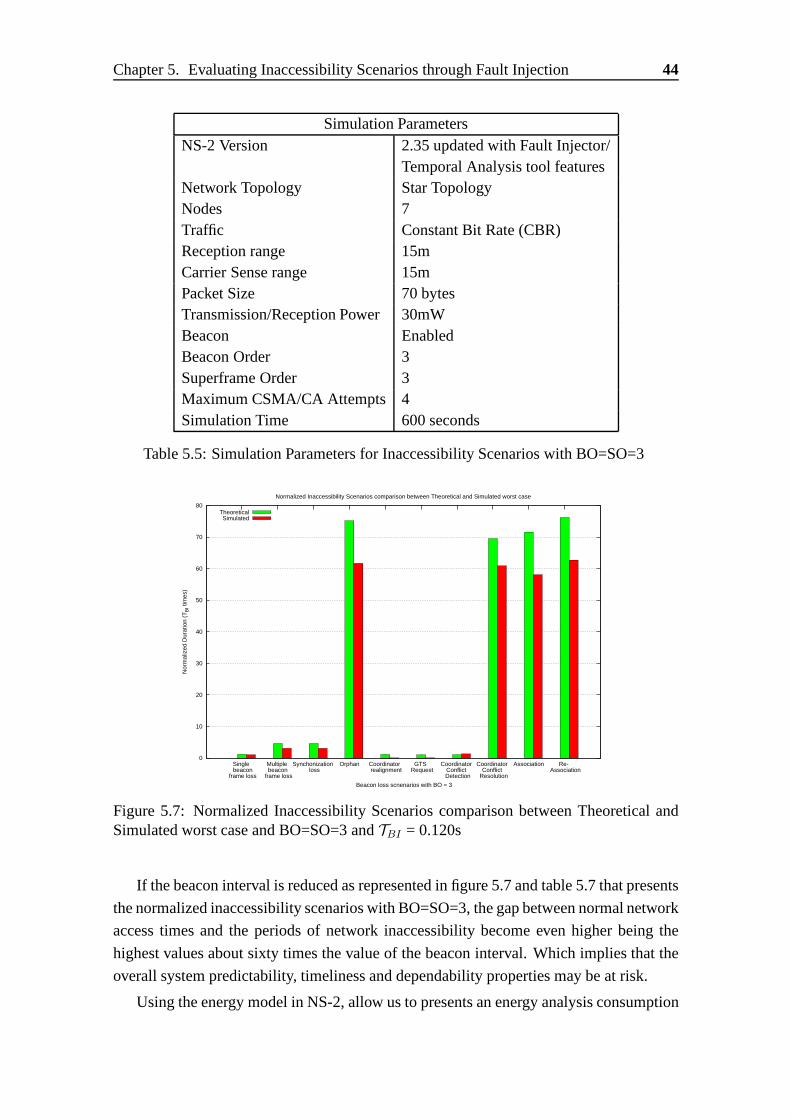
Chapter 5. Evaluating Inaccessibility Scenarios through Fault Injection 44
Simulation ParametersNS-2 Version 2.35 updated with Fault Injector/
Temporal Analysis tool featuresNetwork Topology Star TopologyNodes 7Traffic Constant Bit Rate (CBR)Reception range 15mCarrier Sense range 15mPacket Size 70 bytesTransmission/Reception Power30mWBeacon EnabledBeacon Order 3Superframe Order 3Maximum CSMA/CA Attempts 4Simulation Time 600 seconds
Table 5.5: Simulation Parameters for Inaccessibility Scenarios with BO=SO=3
0
10
20
30
40
50
60
70
80
Single beacon
frame loss
Multiple beacon
frame loss
Synchonization loss
Orphan Coordinator realignment
GTS Request
Coordinator Conflict Detection
Coordinator Conflict
Resolution
Association Re- Association
Nor
mal
ized
Dur
atio
n (T
BI t
imes
)
Beacon loss scnenarios with BO = 3
Normalized Inaccessibility Scenarios comparison between Theoretical and Simulated worst case
TheoreticalSimulated
Figure 5.7: Normalized Inaccessibility Scenarios comparison between Theoretical andSimulated worst case and BO=SO=3 andTBI = 0.120s
If the beacon interval is reduced as represented in figure 5.7and table 5.7 that presents
the normalized inaccessibility scenarios with BO=SO=3, the gap between normal network
access times and the periods of network inaccessibility become even higher being the
highest values about sixty times the value of the beacon interval. Which implies that the
overall system predictability, timeliness and dependability properties may be at risk.
Using the energy model in NS-2, allow us to presents an energyanalysis consumption

Chapter 5. Evaluating Inaccessibility Scenarios through Fault Injection 45
Inaccessibility Scenarios Comparison in s
Scenario Theoretical Best Theoretical Worst Simulated
Single Beacon Frame Loss 0.139 0.139 0.122
Multiple Beacon Frame Loss 0.139 0.554 0.368
Synchronization Loss 0.554 0.554 0.368
Orphan Node 0.582 9.023 7.404
Coordinator Realignment 0.015 0.137 0.004
GTS Request 0.002 0.120 0.001
Coordinator Conflict Detection 0.003 0.126 0.001
Coordinator Conflict Resolution 0.505 8.341 7.308
Association 0.509 8.592 6.973
Re-Association 1.062 9.145 7.526
Table 5.6: Theoretical best and worst case and simulated results for each network inac-cessibility scenario with BO=SO=3 andTBI = 0.120s
Inaccessibility Scenarios Comparison in Periods (TBI )
Scenario Theoretical Best Theoretical Worst Simulated
Single Beacon Frame Loss 1.150 1.160 1.010
Multiple Beacon Frame Loss 1.150 4.600 3.060
Synchronization Loss 4.600 4.600 3.060
Orphan Node 4.850 75.190 61.700
Coordinator Realignment 0.125 1.140 0.032
GTS Request 0.016 1.000 0.010
Coordinator Conflict Detection 0.025 1.050 1.300
Coordinator Conflict Resolution 4.200 69.500 60.900
Association 4.200 71.600 58.100
Re-Association 8.850 76.200 62.710
Table 5.7: Normalized theoretical best and worst case results for each network inaccessi-bility scenario with BO=SO=3 andTBI = 0.120s
during the inaccessibility scenarios as illustrated in figure 5.8. The energy analysis is
always related to the node experiencing the inaccessibility event. We can observe that the
energy consumed by the node greatly increases with the inaccessibility events related with
the beacon loss, being the Re-Association the event that most expended energy during the
simulation. On the figure 5.9 we can observe that with the lower BO, the duty-cycle, the
active period, increase and consequently the activity timeof nodes too. Once again we
can observe the negative impact of inaccessibility events on the energy consumption of
the nodes. The worst case scenarios are related to forced scanning procedures such as

Chapter 5. Evaluating Inaccessibility Scenarios through Fault Injection 46
0
0.002
0.004
0.006
0.008
0.01
0.012
0.014
Normal Frame
transmission
Single beacon
frame loss
Multiple beacon
frame loss
Synchonization loss
Orphan Coordinator realignment
GTS Request
Coordinator Conflict Detection
Coordinator Conflict
Resolution
Association Re- Association
Ene
rgy
(J)
Beacon loss scnenarios with BO = 4
Energy analysis consumption comparison between Inaccessibility Scenarios and a normal transmission
Energy Consumed
Figure 5.8: Energy analysis consumption of Inaccessibility Scenarios with BO=4
Orphan node, Coordinator conflict resolution, Associationand Re-Association. All this
scenarios imply more uptime from the node transceivers.
0
0.002
0.004
0.006
0.008
0.01
0.012
0.014
Normal Frame
transmission
Single beacon
frame loss
Multiple beacon
frame loss
Synchonization loss
Orphan Coordinator realignment
GTS Request
Coordinator Conflict Detection
Coordinator Conflict
Resolution
Association Re- Association
Ene
rgy
(J)
Beacon loss scnenarios with BO = 3
Energy analysis consumption comparison between Inaccessibility Scenarios and a normal transmission
Energy Consumed
Figure 5.9: Energy analysis consumption of Inaccessibility Scenarios with BO=3

5.7 Summary
This chapter described our simulation results and the validation of a previous theoretical
study. We presented, absolute and normalized results regarding the duration of inaccessi-
bility events as well as energetic analyses about the impactof inaccessibility on the node
energy consumption.
All the simulated results are lower than the theoretical, this can be explained by deter-
ministic behaviour of the network simulator.
The WSNs are severely limited in terms of power consumption,which makes energy
efficiency a very important design requirement. The presented results show that inacces-
sibility events greatly increase the power consumption on the nodes.
With the potential of the WSNs to support the communication in scenarios with tem-
poral restrictions, this validation is important, allowing the provision of important simula-
tion values about inaccessibility durations and energeticconsumptions. This results assist
in the characterization of relevant temporal aspects of thecommunication infrastructure,
helping the choice to use of the IEEE 802.15.4 face to the temporal requirements needed
by the application executed on top of the communication infrastructure.

Chapter 5. Evaluating Inaccessibility Scenarios through Fault Injection 48
Chapter 6
Conclusion
The objective of this thesis was through simulation validate the results obtained in the pre-
vious theoretical study about network inaccessibility in IEEE 802.15.4 wireless commu-
nications, by providing tools capable of measure network inaccessibility on a simulation
environment. In this way significant improvement and modifications in the NS-2 simula-
tor IEEE 802.15.4 module were presented, as well as new module allowing the corruption
of specific frames which is not possible with the current error model, and without which
we could not perform the simulation and evaluation of all network inaccessibility scenar-
ios. The current IEEE 802.15.4 module implemented in NS-2 ismodified and extended to
include the use of the GTS mechanisms based on the standard. So, the operations of the
GTS allocation, use and deallocation are implemented. The addition of unimplemented
MAC operations enhanced the simulation module so that is in accordance to the standard.
Based on NS-2 simulations, we evaluate the performance of various features in the
IEEE 802.15.4 MAC. We find that data transmission during the CAP reduces energy
cost due to idle listening in the backoff period but increases the collision at higher rate
and larger number of sources. While the use of GTS in the CFP can allow dedicated
bandwidth to a device to ensure low latency, the device need to track the beacon frames
in this mode, which increases the energy cost. The addition of available channels to scan
during association revealed an increase of the associationtime an energy cost, but made
the NS-2 more compliant to the standard.
In current simulations, rare features about energy consumption can be specified. If
we could get more ways to control the features of energy consumption mechanisms, the
simulation will be able to reveal the real situation better.However the presented results
show that inaccessibility events greatly increase the power consumption on the nodes and
because the energy efficiency is a very important design requirement in WSN this factor
cannot be overlooked.
With this simulation, the previous theoretical model[31] was validated providing a
fundamental source of information about relevant temporalaspects of the IEEE 802.15.4
beacon-enabled networks. Being aware of the worst case, in network inaccessibility sce-
49

Chapter 6. Conclusion 50
narios allow us to establish a known bound, so we can do betteranalysis and definition of
a robust timeliness model, in order to achieve an effective support to real-time operation
in IEEE 802.15.4 networks.This greatly assists the IEEE 802.15.4 standard related research. To benefit the re-
search community, our NS-2 implementation of this protocolis publicly available onlineat: http://www.karyon-project.eu/wp-content/uploads/2012/10/ns-2-2.35-with-gts.tar.gz.
Bibliography
[1] G. Anastasi, M. Conti, and M. Di Francesco. A Comprehensive Analysis of theMAC Unreliability Problem in IEEE 802.15.4 Wireless SensorNetworks.IndustrialInformatics, IEEE Transactions, February 2011.
[2] M. Aoun and P. van der Stok. Overloading an IEEE 802.15.4 Point-to-Point Connec-tion with Real-Time Messages.31st IEEE Real-Time Systems Symposium, Novem-ber 2010.
[3] E. Casilari, J. Cano-Garcıa, and G. Campos-Garrido. Modeling of current consump-tion in 802.15.4/ZigBee sensor motes.Sensors (Basel, Switzerland), June 2010.
[4] C. Chen, B. Yaw Shih, C. Chang, and A. Chen. Enhanced MAC channel selec-tion to improve performance of IEEE 802.15.4.International Journal of InnovativeComputing, Information and Control, December 2010.
[5] W. Choi and S. Lee. Implementation of the IEEE 802.15.4 module with CFP inNS-2. Telecommunication Systems, April 2013.
[6] D. Dondi, A. Bertacchini, S. Scorcioni, L. Larcher, and P. Pavan. Enhancing Safetyin Vehicles with Implement or Trailer using an Autonomous Wireless Sensor Net-work System.IEEE International Conference on Vehicular Electronics and Safety,July 2012.
[7] B. Fateh, M. Govindarasu, and A. Layer. Energy-aware Adaptive MAC Protocol forReal-time Sensor Networks.IEEE International Conference on Communications(ICC), June 2011.
[8] H., Hartenstein, and K.P. Laberteaux. A Tutorial Surveyon Vehicular Ad Hoc Net-works. IEEE Communications Magazine, June 2008.
[9] S. Han, X. Zhu, A. Mok, D. Chen, and M. Nixon. Reliable and Real-Time Commu-nication in Industrial Wireless Mesh Networks.17th IEEE Real-Time and EmbeddedTechnology and Applications Symposium, April 2011.
[10] L. Hou and N. Bergmann. System Requirements for Industrial Wireless SensorNetworks . IEEE Conference on Emerging Technologies and Factory Automation(ETFA), September 2010.
[11] IEEE 802.15.4. Part 15.4: Wireless medium access control (MAC) and physicallayer (PHY) specifications for low-rate wireless personal area networks (WPANs) -IEEE standard 802.15.4. IEEE P802.15 Working Group, 2011.
51

Bibliography 52
[12] M. Imran, A. Said, and H. Hasbullah. A survey of simulators, emulators and testbedsfor wireless sensor networks.International Symposium on Information Technology,June 2010.
[13] T. Issariyakul and E. Hossain.Introduction to Network Simulator NS2. Springer US,2009.
[14] J. Rufino J. L. R. Souza, S. Singh. Characterizing inaccessibility in ieee 802.15.4through theoretical models and simulation tools. Technical report, AIR-II TechnicalReport RT-10-08, September 2010.
[15] H. Karl and A. Willig. Protocols and Architectures for Wireless Sensor Netwoks.John Wiley Sons, 2007.
[16] M. Korkalainen, M. Sallinen, N. Karkkainen, and P. Tukeva. Survey of WirelessSensor Networks Simulation Tools for Demanding Applications.Fifth InternationalConference on Networking and Services, 2009.
[17] A. Koubaa, M. Alves, B. Nefzi, and Y. Song. Improving theIEEE 802.15.4 SlottedCSMA/CA MAC for Time-Critical Events in Wireless Sensor Networks. Technicalreport, Polytechnic Institute of Porto, July 2006.
[18] Philip Levis and Nelson Lee. TOSSIM : A Simulator for TinyOS Networks. 2003.
[19] A. Mainwaring, D. Culler, J. Polastre, R. Szewczyk, andJ. Anderson. Wirelesssensor networks for habitat monitoring.Proceedings of the 1st ACM internationalworkshop on Wireless sensor networks and applications - WSNA ’02, 2002.
[20] NS-2. The network simulator version 2 contributed code.http://nsnam.isi.edu/nsnam/index.php/Contributed_Code/,2013. [Online; accessed 26-September-2013].
[21] NS-2. Ns-2: The network simulator version 2.http://www.isi.edu/nsnam/ns/, 2013. [Online; accessed 26-September-2013].
[22] NS-3. The network simulator version 3.http://www.nsnam.org/, 2013.[Online; accessed 26-September-2013].
[23] Omnet++. Discrete event simulation system.http://www.omnetpp.org/,2013. [Online; accessed 26-September-2013].
[24] OPNET. Opnet:application and network performance tool.http://www.opnet.com, 2013. [Online; accessed 26-September-2013].
[25] M. Park, K. Kim, and C. Lee. Holistic Optimization of Real-Time IEEE802.15.4/ZigBee Networks.IEEE International Conference on Advanced Informa-tion Networking and Applications, 2011.
[26] Prowler. Probabilistic wireless network simulator.http://www.isis.vanderbilt.edu/Projects/nest/prowler/,2013. [Online; accessed 26-September-2013].

Bibliography 53
[27] J. Akerberg, M. Gidlund, and M. Bjorkman. Future research challenges in wirelesssensor and actuator networks targeting industrial automation. In 9th IEEE Interna-tional Conference on Industrial Informatics (INDIN), 2011.
[28] L. Rodrigues and P. Verissimo. AMp : A Highly Parallel Atomic Multicast Protocol.ACM SIGCOM’89 Symposium, September 1989.
[29] X. Shuai and Z. Zhang. Research of Real-Time Wireless Networks Control SystemMAC Protocol.Journal of Networks, Apr 2010.
[30] H. Song, Z. Xiuming, A.K. Mok, C. Deji, and M. Nixon. Reliable and real-timecommunication in industrial wireless mesh networks. In17th IEEE Real-Time andEmbedded Technology and Applications Symposium (RTAS), 2011.
[31] J. Souza and J. Rufino. Characterization of inaccessibility in wireless networks - acase study on IEEE 802.15.4 standard. InIFIP 3th International Embedded SystemSimposium IESS, September 2009.
[32] J. Souza and J. Rufino. An approach to enhance the timeliness of wireless communi-cations. In5th International Conference on Mobile Ubiquitous Computing, Systems,Services and Technologies (UBICOMM), Lisbon, 2011.
[33] J. Souza, J. Rufino, and A. Guerreiro. Characterizing Inaccessibility in IEEE802.15.4 Through Theoretical Models and Simulation Tools.In 4th Symposiumon Informatics (INForum), September 2012.
[34] T. Stone, R. Alena, J. Baldwin, and P. Wilson. A viable COTS based wireless archi-tecture for spacecraft avionics. InIEEE Aerospace Conference, 2012.
[35] Z. Teng and K. Kim. A Survey on Real-Time MAC Protocols inWireless SensorNetworks.Communications and Network, 2010.
[36] Z. Ting, H. Sharif, M. Hempel, P. Mahasukhon, W. Wei, andM. Tao. A novel adap-tive distributed cooperative relaying MAC protocol for vehicular networks. IEEEJournal on Sel. Areas in Communications., 2011.
[37] P. Verıssimo and J. Alves Marques. Reliable broadcastfor fault-tolerance on localcomputer networks. InNinth Symposium on Reliable Distributed Systems. IEEE,1990.
[38] P. Verıssimo and L. Rodrigues.Distributed Systems for System Architects. KluwerAcademic Publishers, 2001.
[39] P. Verıssimo, J. Rufino, and L. Rodrigues. Enforcing real-time behaviour on LAN-based protocols.10th IFAC Workshop on Distributed Computer Control Systems,September 1991.
[40] S. Xiao-Ying and Z. Zhen-Chao. Research of real-time wireless networks controlsystem MAC protocol.Journal of Networks, 2010.

Bibliography 54
[41] J. Zheng and M. J. Lee.A Comprehensive Performance Study of IEEE 802.15.4,chapter 4, pages 218–237. IEEE Press, Wiley Interscience, June 2006.
[42] X. Zhu, S. Han, P. Huang, A. Mok, and D. Chen. MBStar: A Real-time Communi-cation Protocol for Wireless Body Area Networks.23rd Euromicro Conference onReal-Time Systems, 2011.