stativolt Ò utility & industrial
TRANSCRIPT
StatiVolt Ò Utility & Industrial Inverters & DC-AC UPS
Inverter UPS Specs 2020-04-08 ã Staticon Ltd. 2020 1
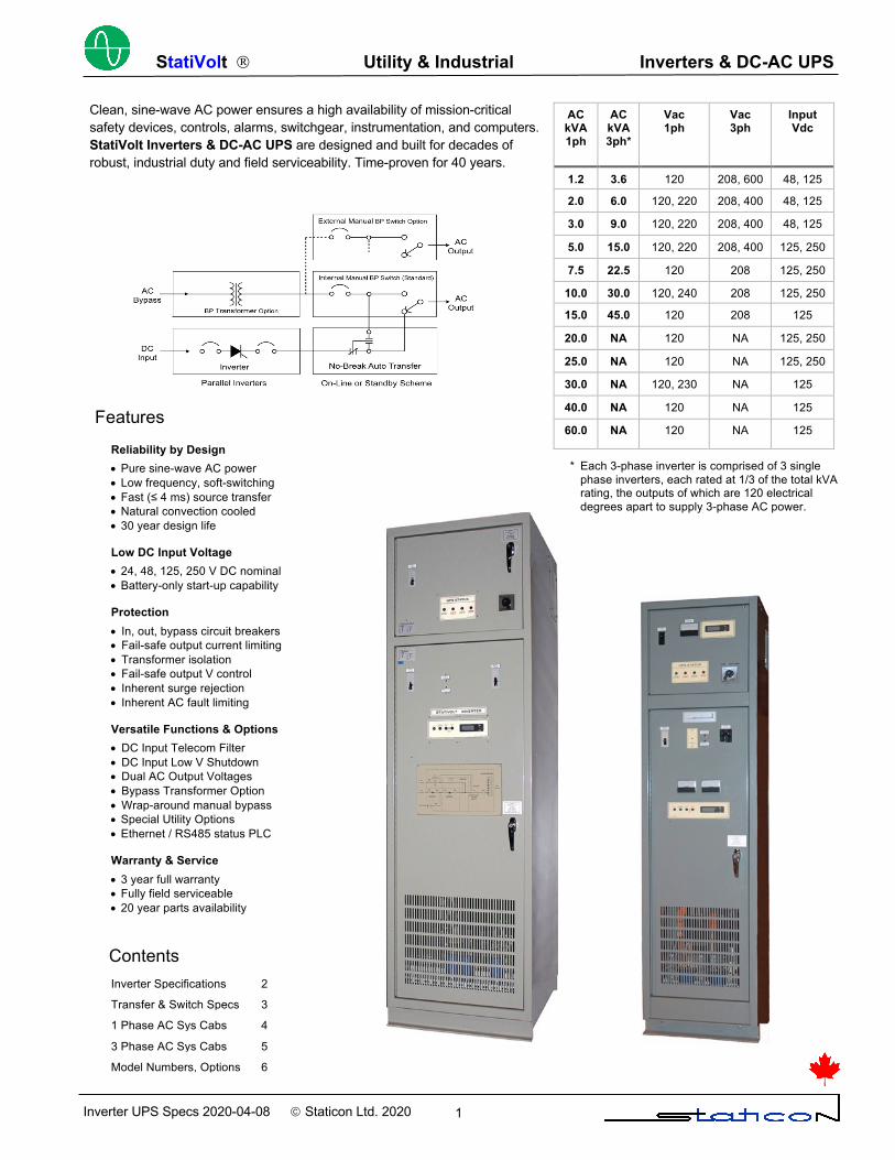
AC kVA 1ph
AC kVA 3ph*
Vac 1ph
Vac 3ph
Input Vdc
1.2 3.6 120 208, 600 48, 125 2.0 6.0 120, 220 208, 400 48, 125
3.0 9.0 120, 220 208, 400 48, 125 5.0 15.0 120, 220 208, 400 125, 250
7.5 22.5 120 208 125, 250
10.0 30.0 120, 240 208 125, 250
15.0 45.0 120 208 125 20.0 NA 120 NA 125, 250 25.0 NA 120 NA 125, 250
30.0 NA 120, 230 NA 125
40.0 NA 120 NA 125
60.0 NA 120 NA 125
Features
Clean, sine-wave AC power ensures a high availability of mission-critical safety devices, controls, alarms, switchgear, instrumentation, and computers. StatiVolt Inverters & DC-AC UPS are designed and built for decades of robust, industrial duty and field serviceability. Time-proven for 40 years.
Features
Reliability by Design • Pure sine-wave AC power • Low frequency, soft-switching • Fast (≤ 4 ms) source transfer • Natural convection cooled • 30 year design life
Low DC Input Voltage • 24, 48, 125, 250 V DC nominal • Battery-only start-up capability Protection • In, out, bypass circuit breakers • Fail-safe output current limiting • Transformer isolation • Fail-safe output V control • Inherent surge rejection • Inherent AC fault limiting Versatile Functions & Options • DC Input Telecom Filter • DC Input Low V Shutdown • Dual AC Output Voltages • Bypass Transformer Option • Wrap-around manual bypass • Special Utility Options • Ethernet / RS485 status PLC
Warranty & Service • 3 year full warranty • Fully field serviceable • 20 year parts availability
Contents Inverter Specifications 2
Transfer & Switch Specs 3
1 Phase AC Sys Cabs 4 3 Phase AC Sys Cabs 5
Model Numbers, Options 6
* Each 3-phase inverter is comprised of 3 single phase inverters, each rated at 1/3 of the total kVA rating, the outputs of which are 120 electrical degrees apart to supply 3-phase AC power.
StatiVolt Ò Utility & Industrial Inverters & DC-AC UPS
Inverter UPS Specs 2020-04-08 ã Staticon Ltd. 2020 2
AC kVA 1ph
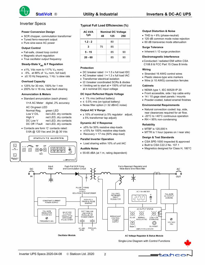
Nominal DC Voltage 48 125 250
1.2 - 2 80 3 75 85
5 - 15 85 90
20 - 60 85 90
Inverter Specs Typical Full Load Efficiencies (%)
Single-Line Diagram with Control Functions
Power Conversion Design • SCR chopper, commutation transformer • Tuned ferro-resonant output • Pure sine-wave AC power
Output Control • Fail-safe, closed loop control • Magnetic shunt regulation • True oscillator output frequency
Steady-State Vac & F Regulation • ±1%, Vdc nom to 117% Vdc nom) • -5%, at 88% of Vdc nom, full load) • ±0.10 Hz frequency, 1 Hz / s slew rate
Overload Capacity • 125% for 30 min, 150% for 1 min • 200% for ≤ 16 ms, load fault clearing
Annunciation & Meters • Standard annunciation (each phase): V+A AC Meter digital, 2% accuracy AC On green LED Normal Reg. green LED Low V O/L red LED, dry contacts High V red LED, dry contacts DC Low V red LED, dry contacts DC Off / Fault red LED, dry contacts • Contacts are form ‘C’ contacts rated:
0.6A @ 120 Vac and 2A @ 30 Vdc
Protection • DC breaker rated I ≈ 1.5 x full load IDC • AC breaker rated I ≈ 1.3 x full load IAC • Transformer electrical isolation • I2 t breaker coordinated SCRs & diodes • I limiting set to start at ≈ 150% of full load
at ≥ nominal DC input voltage
DC Input Reflected Ripple Voltage • ≤ 1% rms (without battery) • ≤ 0.5% rms (on typical battery) • Noise filter option (< 32 dBrnC noise)
Output AC V Range • ± 10% of nominal (± 5% regulator adjust,
± 5% transformer tap adjust)
Dynamic AC V Response • ±5% for 50% resistive step-loads • ±10% for 100% resistive step-loads • Recovery < 17 ms (50% step-load)
Parallel Inverter Operation • Load sharing within 10% of unit IAC
Audible Noise • 55-65 dBA (at 1 m, rating dependent)
Output Distortion & Noise • THD is < 6% (phase-neutral) • 120 dB common mode noise rejection • 60 dB transverse mode attenuation
Surge Tolerance • Inherent I / O surge protection
Electromagnetic Interference • Conducted / radiated EMI within CSA C108.8 & FCC Part 15 Class B limits
Wiring • Stranded 16 AWG control wires • Plastic sleeve-type wire markers • Wire (≤ 10 AWG) connection ferrules
Cabinets • NEMA type 1, IEC 60529 IP 20 • Front accessible, side / top cable entry • 14 / 10 gage steel panels / mounts • Powder-coated, baked enamel finishes
Environmental Requirements • Natural convection cooled: top, side,
rear clearances required for air flow. • -20°C to +40°C continuous operation • RH < 95% non-condensing
Reliability • MTBF is 120,000 h • MTTR is 1 hour (spares on / near site)
Design & Test Standards • CSA SPE-1000 inspected & approved • Built to CSA C22.2 No. 107.1 • Magnetics designed for Class H, 180°C
StatiVolt Ò Utility & Industrial Inverters & DC-AC UPS
Inverter UPS Specs 2020-04-08 ã Staticon Ltd. 2020 3
No-Break Auto Transfer Specs (On-Line or Standby)
Transfer Design (Robust Fast Break) • On-Line: DC / inverter fail: ≤ 4 ms • Standby: AC source / fail: ≤ 8 ms • V sensing, transistor-based logic • Fast contactor-based transfer • 30 year design life
Protection • Bypass AC breaker, 120% of inverter A • 8 kV contactor impulse withstand V • Isolated and / or fused electronics
Voltage Sensing • Differential V sensing relay • Dropout V, nominal V to -20% adj. • Pickup V, nominal V to -20% adj.
Transfer Logic • Voltage sensing initiated, DC powered • Transistor-based switch • Rated @ 500 V, 12 A • Energizes coil @ 10 Vdc 180 mA • Auto re-transfer, 60 s delayed return • Internal PB transfer test switch
Contactor(s) • Type AEG LS-K • 4 Poles (2 NO, 2 NC), 110 A / pole • Rated @ 690 Vac • 2 parallel contactors used for high
Current 1ph and all 3ph UPS’s
Meters • 1Ф Load AC V&A digital, 2% accuracy • 3Ф Load AC V&A analog, 2% accuracy • Optional
AC Frequency analog, 2% accuracy DC V&A digital, 1% accuracy switch selectable
Annunciation • On-Line Transfer Annunciation
Bypass Avail. grn LED Load on Bypass red LED, dry contacts Load on Inverter grn LED, dry contacts Bypass Unavail. Red LED
• Set of dry (NO+NC) contacts rated: 0.6A @ 120 Vac and 2A @ 20 Vdc
• Standby Transfer Annunciation Inverter Avail. grn LED Load on Inverter red LED, dry contacts Load on Bypass grn LED, dry contacts Inverter Unavail. Red LED
• Set of dry (NO+NC) contacts rated: 0.6A @ 120Vac and 2A @20Vdc
Wiring • Stranded 16 AWG control wires • Plastic sleeve-type wire markers • Wire (≤ 10 AWG) connection ferrules
Environmental Requirements • -20°C to +40°C continuous operation • RH < 95% non-condensing
Reliability • MTBF is 560 k hrs • MTTR is 1 hour (spares on / near site)
Design & Test Standards • CSA SPE-1000 inspected & approved • IEC 60947, UL 508 certified contactors • CSA C22.2 #14 certified contactors
Manual Maintenance Bypass Switch Specs
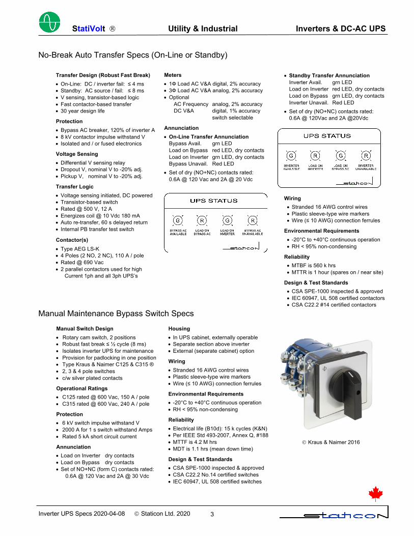
Manual Switch Design • Rotary cam switch, 2 positions • Robust fast break ≤ ½ cycle (8 ms) • Isolates inverter UPS for maintenance • Provision for padlocking in one position • Type Kraus & Naimer C125 & C315 ® • 2, 3 & 4 pole switches • c/w silver plated contacts
Operational Ratings • C125 rated @ 600 Vac, 150 A / pole • C315 rated @ 600 Vac, 240 A / pole
Protection • 6 kV switch impulse withstand V • 2000 A for 1 s switch withstand Amps • Rated 5 kA short circuit current
Annunciation • Load on Inverter dry contacts • Load on Bypass dry contacts • Set of NO+NC (form C) contacts rated:
0.6A @ 120 Vac and 2A @ 30 Vdc
Housing • In UPS cabinet, externally operable • Separate section above inverter • External (separate cabinet) option
Wiring • Stranded 16 AWG control wires • Plastic sleeve-type wire markers • Wire (≤ 10 AWG) connection ferrules
Environmental Requirements • -20°C to +40°C continuous operation • RH < 95% non-condensing
Reliability • Electrical life (B10d): 15 k cycles (K&N) • Per IEEE Std 493-2007, Annex Q, #188 • MTTF is 4.2 M hrs • MDT is 1.1 hrs (mean down time)
Design & Test Standards • CSA SPE-1000 inspected & approved • CSA C22.2 No.14 certified switches • IEC 60947, UL 508 certified switches
Ó Kraus & Naimer 2016
StatiVolt Ò Utility & Industrial Inverters & DC-AC UPS
Inverter UPS Specs 2020-04-08 ã Staticon Ltd. 2020 4
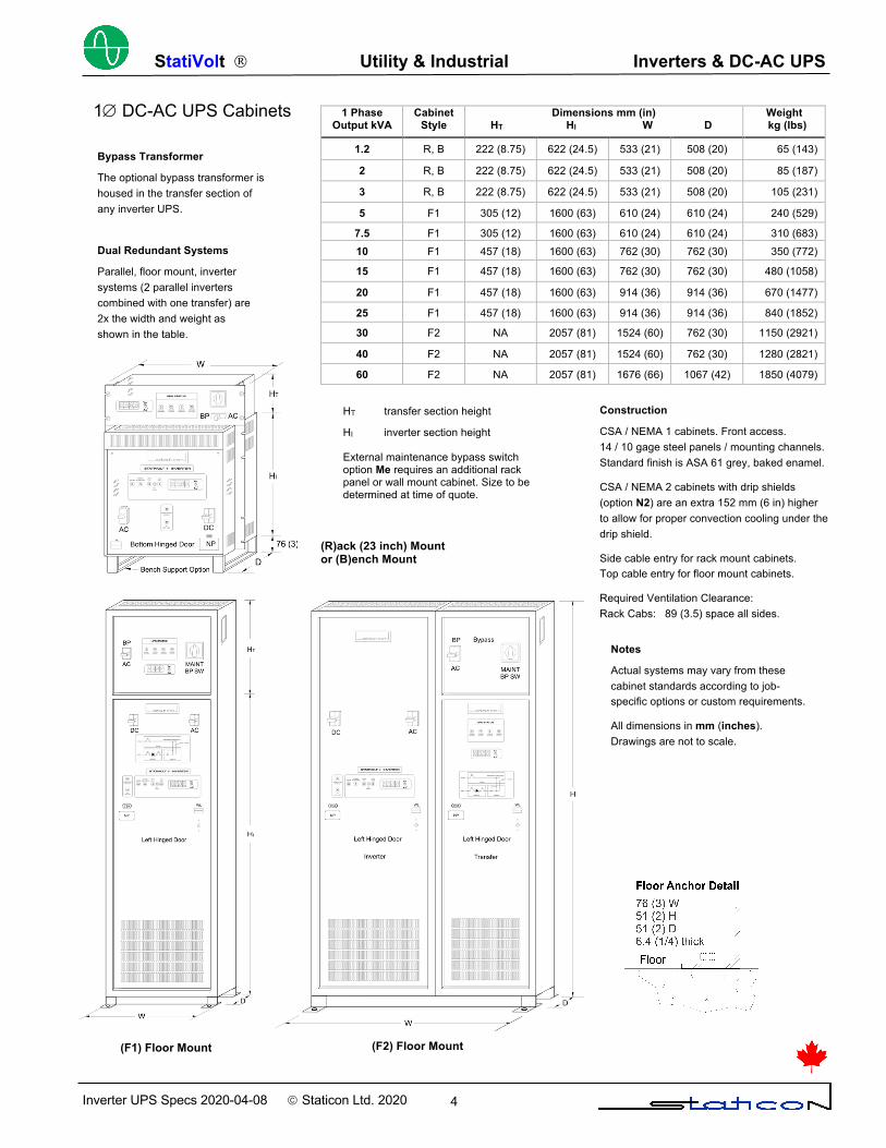
1 Phase Output kVA
Cabinet Style
Dimensions mm (in) HT HI W D
Weight kg (lbs)
1.2 R, B 222 (8.75) 622 (24.5) 533 (21) 508 (20) 65 (143)
2 R, B 222 (8.75) 622 (24.5) 533 (21) 508 (20) 85 (187)
3 R, B 222 (8.75) 622 (24.5) 533 (21) 508 (20) 105 (231)
5 F1 305 (12) 1600 (63) 610 (24) 610 (24) 240 (529)
7.5 F1 305 (12) 1600 (63) 610 (24) 610 (24) 310 (683) 10 F1 457 (18) 1600 (63) 762 (30) 762 (30) 350 (772)
15 F1 457 (18) 1600 (63) 762 (30) 762 (30) 480 (1058)
20 F1 457 (18) 1600 (63) 914 (36) 914 (36) 670 (1477)
25 F1 457 (18) 1600 (63) 914 (36) 914 (36) 840 (1852)
30 F2 NA 2057 (81) 1524 (60) 762 (30) 1150 (2921)
40 F2 NA 2057 (81) 1524 (60) 762 (30) 1280 (2821)
60 F2 NA 2057 (81) 1676 (66) 1067 (42) 1850 (4079)
Dual Redundant Systems
Parallel, floor mount, inverter systems (2 parallel inverters combined with one transfer) are 2x the width and weight as shown in the table.
Bypass Transformer
The optional bypass transformer is housed in the transfer section of any inverter UPS.
Construction
CSA / NEMA 1 cabinets. Front access. 14 / 10 gage steel panels / mounting channels. Standard finish is ASA 61 grey, baked enamel.
CSA / NEMA 2 cabinets with drip shields (option N2) are an extra 152 mm (6 in) higher to allow for proper convection cooling under the drip shield.
Side cable entry for rack mount cabinets. Top cable entry for floor mount cabinets.
Required Ventilation Clearance: Rack Cabs: 89 (3.5) space all sides. Floor Cabs: 305/610 (12/24) rear/top space.
HT transfer section height
HI inverter section height
(R)ack (23 inch) Mount or (B)ench Mount
(F2) Floor Mount (F1) Floor Mount
Notes
Actual systems may vary from these cabinet standards according to job-specific options or custom requirements.
All dimensions in mm (inches). Drawings are not to scale.
1Æ DC-AC UPS Cabinets
External maintenance bypass switch option Me requires an additional rack panel or wall mount cabinet. Size to be determined at time of quote.
StatiVolt Ò Utility & Industrial Inverters & DC-AC UPS
Inverter UPS Specs 2020-04-08 ã Staticon Ltd. 2020 5
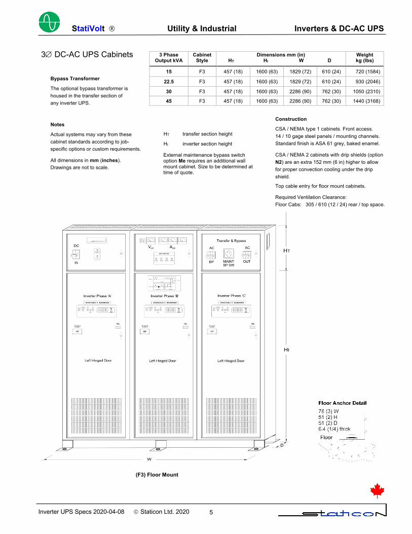
3 Phase Output kVA
Cabinet Style
Dimensions mm (in) HT HI W D
Weight kg (lbs)
15 F3 457 (18) 1600 (63) 1829 (72) 610 (24) 720 (1584)
22.5 F3 457 (18) 1600 (63) 1829 (72) 610 (24) 930 (2046)
30 F3 457 (18) 1600 (63) 2286 (90) 762 (30) 1050 (2310)
45 F3 457 (18) 1600 (63) 2286 (90) 762 (30) 1440 (3168)
3Æ DC-AC UPS Cabinets
Bypass Transformer
The optional bypass transformer is housed in the transfer section of any inverter UPS.
HT transfer section height
HI inverter section height
Construction
CSA / NEMA type 1 cabinets. Front access. 14 / 10 gage steel panels / mounting channels. Standard finish is ASA 61 grey, baked enamel.
CSA / NEMA 2 cabinets with drip shields (option N2) are an extra 152 mm (6 in) higher to allow for proper convection cooling under the drip shield.
Top cable entry for floor mount cabinets.
Required Ventilation Clearance: Floor Cabs: 305 / 610 (12 / 24) rear / top space.
Notes
Actual systems may vary from these cabinet standards according to job-specific options or custom requirements.
All dimensions in mm (inches). Drawings are not to scale.
(F3) Floor Mount
External maintenance bypass switch option Me requires an additional wall mount cabinet. Size to be determined at time of quote.
StatiVolt Ò Utility & Industrial Inverters & DC-AC UPS
Inverter UPS Specs 2020-04-08 ã Staticon Ltd. 2020 6
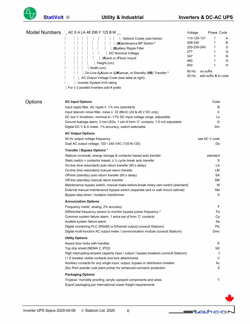
Options
Voltage Phase Code 110-120-127 1 A 208-240 1 B 220-230-240 1 U 277 1 Q 347 1 N 480 1 G 600 1 H 60 Hz: no suffix 50 Hz: add suffix X to code
DC Input Options Code Input ripple filter, AC ripple ≤ 1% rms (standard) B Input telecom noise filter, noise ≤ 32 dBrnC (24 & 48 V DC only) C DC low V shutdown, nominal to -17% DC input voltage range, adjustable Ls Ground leakage alarm, 2 red LEDs, 1 set of form ‘C’ contacts, 1-5 mA adjustable G Digital DC V & A meter, 1% accuracy, switch selectable Dm AC Output Options 50 Hz output voltage frequency see AC V code Dual AC output voltage, 120 / 240 VAC (120-N-120) Do Transfer / Bypass Options * Staticon no-break, energy storage & contactor based auto transfer standard Static switch + contactor based, ≤ ¼ cycle break auto transfer S On-line (line redundant) auto return transfer (60 s delay) LA On-line (line redundant) manual return transfer LM Off-line (standby) auto return transfer (60 s delay) SA Off-line (standby) manual return transfer SM Maintenance bypass switch, manual make-before-break rotary cam switch (standard) M External manual maintenance bypass switch (separate rack or wall mount cabinet) Me Bypass step-down / isolation transformer X
Annunciation Options Frequency meter, analog, 2% accuracy F Differential frequency sensor to monitor bypass power frequency * Fd Common system failure alarm, 1 extra set of form ‘C’ contacts Ca Audible system failure alarm Aa Digital monitoring PLC (RS485 or Ethernet output) (consult Staticon) Plc Digital multi-function AC output meter / communication module (consult Staticon) Dmc Utility Options Keyed door locks with handles K Top drip shield (NEMA 2, IP22) N2 High interrupting-ampere capacity input / output / bypass breakers (consult Staticon) I I / O breaker visible contacts and lock attachments V Auxiliary contacts for any single input, output, bypass or distribution breaker Ac Zinc Rich powder coat paint primer for enhanced corrosion protection Z Packaging Options Tropical / humidity proofing, acrylic sprayed components and wires T Export packaging per international ocean freight requirements * For DC-AC UPS only. Omit for inverters without transfer systems.
Model Numbers _ AC 6 A LA 48 206 F 125 B M __ ½ ½ ½ ½ ½ ½ ½ ½ ½ ½ ë Options Codes (see below) ½ ½ ½ ½ ½ ½ ½ ½ ½ ë (M)aintenance BP Switch * ½ ½ ½ ½ ½ ½ ½ ½ ë (B)attery Ripple Filter ½ ½ ½ ½ ½ ½ ½ ë DC Nominal Voltage ½ ½ ½ ½ ½ ½ ë (R)ack or (F)loor mount ½ ½ ½ ½ ½ ë Height (cm) ½ ½ ½ ½ ë Width (cm) ½ ½ ½ ë On-Line (LA)uto or (LM)anual, or Standby (SB) Transfer * ½ ½ ë AC Output Voltage Code (see table at right) ½ ë Inverter System kVA rating ë For ≥ 2 parallel inverters add # prefix