pedro ferreira da costa - universidade do minho · os bioreactores têm potencial para gerar...
TRANSCRIPT

Pedro Ferreira da Costa
dezembro de 2013UM
inho
|201
3
Development of advanced cell/tissue culture systems, based on enhanced polymericscaffolds and sophisticated bioreactors, for tissue engineering applications
Universidade do Minho
Escola de Engenharia
Ped
ro F
erre
ira
da C
osta
Deve
lop
me
nt
of
ad
van
ce
d c
ell/t
issu
e c
ult
ure
sys
tem
s,
ba
sed
on
en
ha
nce
d p
oly
me
ric s
ca
ffo
lds
an
d s
op
his
tica
ted
b
iore
acto
rs,
for
tiss
ue
en
gin
ee
rin
g a
pp
lica
tio
ns
Programa Doutoral em Engenharia Biomédica
Trabalho realizado sob a orientação do
Professor Doutor Rui L. Reis
e da
Professora Doutora Manuela E. Gomes
Pedro Ferreira da Costa
dezembro de 2013
Development of advanced cell/tissue culture systems, based on enhanced polymericscaffolds and sophisticated bioreactors, for tissue engineering applications
Universidade do Minho
Escola de Engenharia

iii
In loving memory of my mother

iv

v
Acknowledgements
During the course of my PhD, several people have contributed to the accomplishment of this thesis,
both professionally and personally.
First of all, I would like to acknowledge my thesis supervisor, Professor Rui Reis, for giving me the
oportunity to work in such a renowned research group as the 3B’s. I would like to thank him for
showing me that science can be much more than just having good ideas and that it doesn’t necessarily
need to be confined to a conventional research lab. I would like to thank him for expanding my horizons
to other realities such as industry, business and intelectual property.
I would also like to acknowledge my co-supervisor at 3B’s, Professor Manuela Gomes for her guidance,
reviewing criticism and support despite her very busy agenda, in particular during the final stage of the
preparation of this thesis.
Furthermore, I would also like to thank my supervisor in Australia, Professor Dietmar Hutmacher, for
hosting me in his lab as part of his team. Working on the other side of the world can be tough
sometimes but due to his kindness I have been able to feel at home and part of a big family. I am
deeply grateful to him for showing me that, despite being very competitive, science can still be humane
and fun.
In particular, I would like to deeply thank Dr. Cédryck Vaquette and Dr. Albino Martins who, apart from
being my truthful friends, have been crucial in the development of the work described in this PhD
thesis. Either in Australia or Portugal I have always been able to count on their unconditional support,
guidance and friendly advice.
I would also like to acknowledge all the co-authors in the publications described in this thesis for their
scientific input and for their contributions into improving the quality of the work described in this thesis.
During my stay at Materialise (Belgium) I have also been lucky enough to meet fantastic people who,
despite distance and time, I will always remember. Dr. Erik Boelen has been my direct supervisor
during that time and from whom I’ve learned so much about medical image processing, rapid
prototyping, business development and product development in industrial environment. I also
aknowledge his patience since that was the first time I worked for an extended time both abroad and in
an industrial environment. I would also like to thank Jeroen Dille and Dr. Roel Wirix-Speetjens for their
guidance and support. I also want to dedicate a special thank to my colleagues and friends at
Materialise’s sofware division namely Patricia Lopes, Bart Veeckmans, Dimitri Vanlessen, Davy Willems,

vi
Wim Claassen and in particular my friends Sophie Lauwers and Thomas Van Mechelen who have made
my stay at Materialise very pleasant and amusing.
Also, a special thank to my colleagues and friends at Queensland University of Technology (Australia),
namely Christina Theodoropoulos, Toby Brown, Ferry Melchels, Anna Taubenberger, Laure Thibaudeau,
Jana Wrobel, Fabio Volpato, Anna Slotosch and Jeremy Baldwin who have made my life in the lab (and
also outside the lab) so much easier and fun.
To finalize my professional acknowledgements, I would like to dedicate a special thank to the present
and former colleagues at the 3B’s group.
I should also acknowledge the Portuguese Foundation for Science and Technology (FCT) for my PhD
grant SFRH/BD/62452/2009, the North Portugal Regional Operational Programme (ON.2 – O Novo
Norte), under the National Strategic Reference Framework (NSRF), through the European Regional
Development Fund (ERDF) and the HIPPOCRATES (NMP3-CT-2003-505758), DISC REGENERATION
(NMP3-LA-2008-213904) and MARIE CURIE ALEA JACTA EST (MEST-CT-2004-008104) european
projects for funding.
At a personal level, I would also like to show my deepest appreciation for some people. First of all, my
father and my brother who have been so important throughout my growth and with whom I’ve had the
priviledge to share the best and worst moments of my life. A special thank to my mother who has
strongly molded my personality and taught me to never give up.
Also, my good friends Vitor Martins and Filipe Noronha who despite following separate paths have
always kept close and always made me feel that my life and work are meaningful.
Last but not least, a special thank to Ana, my better half, who has made my life so much happier and
has supported me so much ever since I met her.

vii
Development of advanced cell/tissue culture systems, based on enhanced polymeric scaffolds
and sophisticated bioreactors, for tissue engineering applications
Abstract
In a typical tissue engineering approach, cells are collected from the patient and then seeded into a three-
dimensional scaffold where they proliferate to generate a tissue-like substitute to be re-implanted back into
the defect site. However, human tissues possess various degrees of complexity which often makes them
impossible to be reproduced in such a simplified way. In fact, many tissues such as bone, for example,
exhibit specific architectures and shapes, mechanical properties and cellular content that are very
challenging to reproduce, in particular when combined together into a single construct. In order to overcome
the limitations found in the generation of complex tissues such as bone and bone interfaces with other
tissues, various automated technologies have been adopted by tissue engineering approaches to help
generate viable tissue substitutes in a time- and cost-effective way.
Bioreactors are automated systems where cell-seeded scaffolds can be cultured under highly controlled
conditions to generate replacement tissues. They improve the mobility of nutrients and avoid cell death in
internal regions of constructs and influence cellular development through biomechanical stimuli. Bioreactors
show the potential to generate constructs in a more standardized, traceable, cost-effective, safe and
regulatory-compliant way.
Additive manufacturing is another highly automated technology which has more recently been introduced
into tissue engineering. Its main use has been in producing 3D scaffolds with highly defined architectures by
layer-by-layer deposition of materials. Herein we proposed the utilization of additive manufacturing to build
simultaneously and concomitantly a 3D scaffold and bioreactor chamber, from different materials, as a
single object. This would allow to produce scaffolds readily contained into bioreactor chambers, reducing
the necessity for assembling, hence reducing production time and cost as well as the contamination risk
due to the significantly decreased manipulation of both the scaffold and bioreactor.
In a first approach we aimed at applying this concept to the generation of tailor-made constructs for defect-
and patient-specific applications. By resorting to medical imaging, a 3D model of a tibia bone tissue section
was obtained and utilized as a template for generating a porous tissue replica scaffold as well as an
enclosing culture chamber tightly fitting the outer shape of the porous scaffolds. The device showed to be
able to homogenously distribute cells throughout the scaffold and to keep them viable along a 6 weeks
culture period.
In a second approach, the same concept was used to simultaneouslly seed and culture multiple scaffolds
contained into one single upscalable perfusion culture device. Additionally, the device was used for coating
the scaffolds contained in its interior with a calcium phosphate layer in order to enhance their
viii
osteoinductivity upon implantation. Cultured scaffolds showed homogeneous cell distribution and high cell
viability throughout a 4 weeks culture period and calcium phosphate-coated scaffolds resulted in a
significant increase in cell number. Such device may also find applications in the high throughput screening
of combinations of multiple variable factors such as the selected biomaterials, scaffold architectures, cell
types and culture regimes. Furthermore, this device might be applicable in the simultaneous generation of
large amounts of tissue substitutes in a scenario of widespread adoption of tissue engineering-based
therapies.
Additive manufacturing was also applied to a specific tissue engineering application that requires the
development of a biphasic construct, targeting the generation of bone-periodontal ligament-teeth interfaces
in a guided tissue regeneration strategy. In this case additive manufacturing was combined with the
electrospinning technology to fabricate the biphasic construct, that is potentially able to accommodate a
bone and a periodontal ligament tissue construct in separate cavities. The additively manufactured 3D
scaffold was treated by means of a calcium phosphate coating in order to increase its osteoinductivity and
then attached to a fine electrospun fibrilar mesh. First the additively manufactured part of the scaffold was
seeded with osteoblasts and later the electrospun part was used for depositing cell sheets of periodontal
ligament acting as a biomechanical support. After further culture, the complex constructs were finally
attached to dentin blocks simulating the surface of teeth and subcutaneously implanted into rats. After 8
weeks of implantation, increased bone formation was observed when comparing to non-coated scaffolds.
Histological analysis revealed that the large pore size of the periodontal compartment permitted the
vascularization of the periodontal cell sheets and the formation of a tissue similar to native periodontal
ligament tissue at the interface with dentin. Given the promising results achieved, this new and complex
biphasic scaffold represents therefore a new hope in the regeneration of complex tissue defects resulting
from serious forms of periodontitis.
Finally, a study was performed to evaluate the feasibility of cryopreservation-based storage and later off-the-
shelf utilization of cell/scaffold constructs showing that cell and scaffold properties can be maintained upon
cryopreservation and that the architecture of porous scaffolds may favor the retention and viability of
construct’s cellular content.
In summary, the work performed in this thesis resulted in significant advances towards automation and
mass production of tailor-made and off-the-shelf tissue engineered products that might facilitate the
widespread clinical adoption of tissue engineering strategies holding the promise to revolutionize the
treatment of damaged tissues.

ix
Desenvolvimento de sistemas avançados de cultura celular/tecidular, com base em
estruturas de suporte melhoradas e bioreactores sofisticados, para aplicações de engenharia
de tecidos
Resumo
Numa típica abordagem de engenharia de tecidos, são recolhidas células de um paciente e utilizadas para
colonizar um suporte tridimensional poroso onde proliferam e geram um substituto tecidular a ser
reimplantado no local danificado. No entanto, a maior parte dos tecidos humanos possui variados graus de
complexidade que impossibilitam a sua reprodução de um modo tão simplificado. Muitos tecidos, tais como
o osso, exibem arquitecturas e formas, propriedades mecânicas e conteúdos celulares difíceis de
reproduzir, particularmente quando combinados num único substituto tecidular. De modo a superar as
limitações encontradas na geração de tecidos complexos, tais como o osso e suas interfaces com outros
tecidos, várias tecnologias automatizadas têm sido adoptadas em estratégias de engenharia de tecidos de
modo a gerar tecidos viáveis de um modo eficiente em termos de tempos e custos de produção.
Bioreactores são sistemas automatizados onde estruturas de suporte celularizadas podem ser cultivadas
sob condições muito controladas de modo a originarem substitutos tecidulares. Melhoram também a
difusão de nutrientes reduzindo a morte celular nas regiões internas dos substitutos tecidulares e
influenciam o desenvolvimento celular por aplicação de estimulação biomecânica. Os bioreactores têm
potencial para gerar substitutos tecidulares de modo standardizado, rastreável, rentável e seguro, de acordo
com as normas aplicáveis.
A fabricação aditiva é outra tecnologia altamente automatizada que foi recentemente introduzida na
engenharia de tecidos, principalmente na produção de suportes celulares 3D com arquitecturas altamente
definidas por deposição de materiais camada-sobre-camada. Nesta tese, propôs-se portanto a utilização de
fabricação aditiva para construir simultânea e concomitantemente uma estrutura de suporte celular 3D e
uma câmara de bioreactor, a partir de materiais diferentes, como um objecto único. Isto permitiria produzir
estruturas de suporte contidas em câmaras de bioreactor reduzindo a necessidade de montagem, o tempo
e custo de produção e o risco de contaminação decorrente da manipulação. Numa primeira abordagem o
objectivo principal consistiu na aplicação deste conceito à geração de substitutos tecidulares personalizados
de acordo com defeitos variáveis em pacientes. Um modelo 3D de uma secção de tibia foi obtido por
imagiologia médica e utilizado para gerar um suporte celular poroso replicando a estrutura do osso assim
como uma câmara de cultura ajustada à forma exterior do suporte celular. O dispositivo foi capaz de
distribuir células homogeneamente pelo suporte celular continuando viáveis durante 6 semanas.
Numa segunda abordagem, o mesmo conceito foi utilizado para colonizar e cultivar simultâneamente
multiplos suportes celulares contidos num único dispositivo expansível de cultura de perfusão.
Adicionalmente, o dispositivo foi usado para recobrir as estruturas de suporte celular com uma camada de

x
fosfato de cálcio de modo a aumentar a sua osteoindutividade após implantação. Tal dispositivo pode ser
aplicável na triagem de alta produtividade envolvendo multiplas variáveis tais como o biomaterial,
arquitectura do suporte celular, tipos celulares e regimes de cultura utilizados. Este dispositivo pode
também ser aplicável na geração simultânea de grandes quantidades de substitutos tecidulares num
cenário de adopção generalizada de terapias de engenharia de tecidos. Os suportes celulares cultivados
revelaram distribuição celular homogénea, alta viabilidade celular e um significativo aumento do conteúdo
celular durante 4 semanas particularmente quando revestidos com fosfato de cálcio.
A fabricação aditiva foi também aplicada especificamente na geração de interfaces osso-ligamento
periodontal-dente por meio de um substituto tecidular bifásico desenvolvido numa estratégia de regeneração
tecidular guiada. Neste caso, a fabricação aditiva foi combinada com tecnologia de electrospinning para
fabricar um substituto tecidular bifásico potencialmente capaz de acomodar substitutos ósseos e
periodontais em cavidades separadas. O suporte celular 3D fabricado aditivamente foi recoberto com
fosfato de cálcio para aumentar a sua osteoindutividade e ligado a uma fina malha fibrilar produzida por
electrospinning. Primeiramente, a parte fabricada aditivamente foi colonizada com osteoblastos e mais
tarde na malha produzida por electrospinning foram depositadas camadas celulares de ligamento
periodontal actuando como um suporte biomecânico. Após cultura, os complexos substitutos tecidulares
foram justapostos a blocos de dentina simulando a superfície dentária e implantados subcutâneamente em
ratos. Após 8 semanas de implantação, uma acentuada formação de osso foi observada quando
comparando com suportes celulares não recobertos. Análises histológicas revelaram também que os largos
poros do compartimento periodontal permitiram a vascularização das camadas celulares periodontais e a
formação de tecido semelhante ao ligamento periodontal nativo no interface com a dentina. Tendo em
conta os bons resultados obtidos, este novo e complexo scaffold bifásico representa assim uma nova
esperança na regeneração de defeitos em casos extremos de periodontite.
Finalmente, foi feito um estudo para avaliar a exequibilidade do armazenamento por criopreservação e
posterior utilização de estruturas de suporte com células demonstrando que as propriedades das células e
scaffolds podem ser mantidas após criopreservação e que a arquitectura de estruturas porosas podem
favorecer a retenção do conteúdo celular e sua viabilidade.
Em resumo, o trabalho desenvolvido no âmbito desta tese resultou em avanços significativos no sentido de
automatizar a produção em massa por engenharia de tecidos de produtos customizados prontos a usar e
assim facilitar a aplicação clínica generalizada de estratégias de engenharia de tecidos que prometem
revolucionar o tratamento de tecidos danificados.
xi
Table of contents
Acknowledgements ............................................................................................................................. v
Abstract ............................................................................................................................................ vii
Resumo ............................................................................................................................................. ix
Table of contents ............................................................................................................................... xi
List of abbreviations and nomenclature ............................................................................................. xix
List of figures .................................................................................................................................... xxi
List of tables ................................................................................................................................... xxix
Short curriculum vitae ..................................................................................................................... xxxi
List of publications ..........................................................................................................................xxxii
Awards .......................................................................................................................................... xxxvi
Structure of the thesis ................................................................................................................... xxxvii
Section I - General introduction ...................................................................................................1
Chapter 1 - Automating the processing steps for obtaining bone tissue engineered
substitutes: from imaging tools to bioreactors ..........................................................................3
Abstract .........................................................................................................................................3
1. Introduction ...............................................................................................................................4
2. Imaging tools for design .............................................................................................................5
3. Design by replication of real tissue models .................................................................................7
4. Fabrication with accuracy and reproducibility .............................................................................9
5. Culturing cells in 3D templates ................................................................................................12
6. Implant ...................................................................................................................................15
7. Off-the-shelf storage of tissue engineered constructs by cryopreservation ..................................16
8. Concluding remarks and future directions ................................................................................16
9. Acknowledgments ....................................................................................................................17
10. References ............................................................................................................................17
Section II - Detailed description of experimental testing and materials ...............................25
Chapter 2 - Materials and methods ...........................................................................................27
1. Materials .................................................................................................................................28
1.1. Polycaprolactone .............................................................................................................28
1.2. Polycaprolactone - β-tricalcium phosphate ........................................................................28
xii
1.3. Poly(lactic) acid ...............................................................................................................29
1.4. Acrylonitrile butadiene styrene (ABS) ................................................................................29
1.5. Starch-Polycaprolactone blend (SPCL) ..............................................................................30
2. Fabrication of Culture devices and Scaffolds .............................................................................30
2.1. Device Design ..................................................................................................................30
2.2. Additive manufacturing of devices and scaffolds by fused deposition modelling (FDM) .......32
2.3. Melt Electrospinning ........................................................................................................33
2.4. Biomimetic coating of the FDM scaffolds ..........................................................................34
2.5. Fiber bonding ..................................................................................................................35
2.6. Injection molding .............................................................................................................35
3. Scaffolds Characterization ........................................................................................................36
3.1. Morphological Characterization ........................................................................................36
3.1.1. Scanning Electron Microscopy ..................................................................................36
3.1.2. Micro computerized tomography ..............................................................................36
3.1.3. Computational fluid flow modelling ...........................................................................37
3.1.4. Atomic Force Microscopy (AFM) ...............................................................................38
3.2. Mechanical characterization .............................................................................................38
3.3. X-Ray diffraction ...............................................................................................................38
4. Biological assays .....................................................................................................................39
4.1. Harvest, Isolation and culture of primary osteoblasts ........................................................39
4.2. Harvest, isolation and culture of primary periodontal ligament cells ..................................40
4.3. Periodontal ligament cell sheets .......................................................................................40
4.4. Harvest, Isolation and culture of goat bone marrow stromal cells ......................................41
4.5. Perfusion culture .............................................................................................................41
4.6. Confocal microscopy .......................................................................................................42
4.7. Metabolic activity staining (MTT) ......................................................................................43
4.8. Metabolic activity quantification (MTS assay) ....................................................................44
4.9. Cell proliferation assay .....................................................................................................44
4.10. Alkaline Phosphatase Quantification (ALP) ......................................................................45
5. In vivo model ...........................................................................................................................45
5.1. Dentin slices and scaffold assembly .................................................................................46
5.2. Subcutaneous implantation into nude rats ........................................................................46

xiii
5.3. Histological analysis of implanted constructs ....................................................................47
6. Seeding, cryopreservation and thawing of cell-seeded porous scaffolds and nonporous discs ....47
7. Statistical Analysis ...................................................................................................................48
8. References ..............................................................................................................................49
Section III - Experimental ............................................................................................................55
Chapter 3 - Bioreactor composed of watertight chamber and internal matrix for the
generation of cellularized medical implants ............................................................................57
Abstract .......................................................................................................................................57
1. Object of the invention .............................................................................................................58
2. State of the art ........................................................................................................................58
3. Description of the invention ......................................................................................................59
4. Brief description of the drawings ..............................................................................................61
5. Detailed description of the invention .........................................................................................62
6. Claims .....................................................................................................................................66
7. Amended claims ......................................................................................................................68
8. Statement under article 19(1) ..................................................................................................70
9. Figures ....................................................................................................................................72
Chapter 4 - Biofabrication of customized bone grafts by combination of additive
manufacturing and bioreactor technologies ............................................................................79
Abstract .......................................................................................................................................79
1. Introduction .............................................................................................................................80
2. Materials and Methods ............................................................................................................81
2.1. Design and fabrication concept ........................................................................................81
2.2. Fluid flow modelling .........................................................................................................82
2.3. Conversion, slicing and prototyping of 3D models .............................................................83
2.4. Bioreactor surface treatment ............................................................................................83
2.5. Scaffold surface treatment ...............................................................................................83
2.6. Micro computerized tomography analysis (Micro-CT) ........................................................84
2.7. In vitro study ...................................................................................................................84
2.8. Metabolic activity staining ................................................................................................85
2.9. Live/dead assay (FDA/PI) ................................................................................................85
2.10. Scanning electron microscopy (SEM) .............................................................................86

xiv
3. Results and discussion ............................................................................................................86
3.1. Fluid flow modelling .........................................................................................................87
3.2. Design, fabrication and post-processing of the device .......................................................89
3.3. Perfusion cell culture .......................................................................................................91
4. Conclusions .............................................................................................................................94
5. Acknowledgements ..................................................................................................................94
6. References ..............................................................................................................................94
Chapter 5 - Additive manufacturing for high throughput screening of 3D tissue engineered
constructs in dynamic culture ....................................................................................................97
Abstract .......................................................................................................................................97
1. Introduction .............................................................................................................................98
2. Experimental ........................................................................................................................ 107
2.1. Design and fabrication concept ..................................................................................... 107
2.2. Fluid flow modelling ...................................................................................................... 108
2.3. Conversion, slicing and prototyping of 3D models .......................................................... 108
2.4. Bioreactor surface treatment ......................................................................................... 109
2.5. Scaffold surface treatment ............................................................................................ 109
2.6. Biomimetic coating of scaffolds ..................................................................................... 109
2.7. Micro computerised tomography analysis (Micro-CT) ..................................................... 109
2.8. In vitro study ................................................................................................................ 110
2.9. DNA content quantification ........................................................................................... 111
2.10. Metabolic activity staining ........................................................................................... 111
2.11. Live/dead assay (FDA/PI) ........................................................................................... 111
2.12. Scanning electron microscopy .................................................................................... 112
3. Acknowledgments ................................................................................................................. 112
4. Supplementary information ................................................................................................... 113
5. References ........................................................................................................................... 114
Chapter 6 - Advanced Tissue Engineering Scaffold Design for Regeneration of the
Complex Hierarchical Periodontal Structure ........................................................................ 119
Abstract .................................................................................................................................... 119
1. Introduction .......................................................................................................................... 120
2. Materials and Methods ......................................................................................................... 122

xv
2.1. Biphasic scaffold fabrication ......................................................................................... 122
2.1.1. Bone compartment ............................................................................................... 122
2.1.2. Periodontal compartment ...................................................................................... 122
2.1.3. Assembly of the biphasic scaffold .......................................................................... 122
2.2. Biphasic scaffold characterization ................................................................................. 123
2.2.1. Scanning electron microscopy (SEM) .................................................................... 123
2.2.2. X-ray diffraction ..................................................................................................... 123
2.3. In vitro study ................................................................................................................ 123
2.3.1. Cell isolation and culture ....................................................................................... 123
2.3.2. Osteoblasts .......................................................................................................... 123
2.3.3. Periodontal ligament cells ..................................................................................... 124
2.3.4. Biphasic scaffold seeding and culture .................................................................... 124
2.3.5. Alkaline phosphatase activity and DNA content ...................................................... 125
2.3.6. Scanning electron microscopy (SEM) .................................................................... 125
2.3.7. Confocal laser microscopy .................................................................................... 125
2.4. Micro-CT analysis ......................................................................................................... 126
2.5. In vivo study ................................................................................................................. 126
2.5.1. Harvesting of cell sheets ....................................................................................... 126
2.5.2. Dentin slices and scaffold assembly ...................................................................... 127
2.5.3. Subcutaneous implantation ................................................................................... 127
2.5.4. Micro-CT analysis ................................................................................................. 127
2.5.5. Histology .............................................................................................................. 128
2.6. Statistical analysis ........................................................................................................ 129
3. Results ................................................................................................................................. 129
3.1. Scaffold morphology ..................................................................................................... 129
3.2. In vitro study ................................................................................................................ 131
3.2.1. Cell imaging ......................................................................................................... 131
3.2.2. DNA content and Alkaline Phosphatase activity ...................................................... 131
3.2.3. Micro-computed tomography ................................................................................. 134
3.3. In vivo study ................................................................................................................. 134
4. Discussion ............................................................................................................................ 137
5. Conclusions .......................................................................................................................... 140
xvi
6. Acknowledgements ............................................................................................................... 140
7. Supplementary information ................................................................................................... 141
7.1. ALP and DNA analysis .................................................................................................. 141
7.2. Harvesting of cell sheets ............................................................................................... 141
8. References ........................................................................................................................... 144
Chapter 7 - Cryopreservation of cell/scaffold tissue engineered constructs ................... 149
Abstract .................................................................................................................................... 149
1. Introduction .......................................................................................................................... 150
2. Materials and Methods ......................................................................................................... 151
2.1. Preparation of porous scaffolds and nonporous discs .................................................... 151
2.2. Cell seeding and culturing onto porous scaffolds and nonporous discs ........................... 151
2.3. Cryopreservation of cell-seeded porous scaffolds and nonporous discs .......................... 152
2.4. Thawing of cell-seeded porous scaffolds and nonporous discs after cryopreservation ...... 152
2.5. Collection of cell-seeded porous scaffold and nonporous disc samples for biological
analysis ................................................................................................................................ 153
2.6. MTS quantification ........................................................................................................ 153
2.7. DNA quantification ........................................................................................................ 154
2.8. Scanning electron microscopy (SEM) ............................................................................ 154
2.9. Micro computerized tomography (micro-CT) .................................................................. 154
2.10. Atomic Force Microscopy (AFM) .................................................................................. 155
2.11. Mechanical analysis .................................................................................................... 155
2.12. Statistics .................................................................................................................... 155
3. Results ................................................................................................................................. 155
3.1. Viability, cellular content and morphology of GBMSCs on porous scaffolds and nonporous
discs before and after cryopreservation ................................................................................ 155
3.2. Morphology, surface topography and architecture of porous scaffolds and nonporous discs
before and after cryopreservation ......................................................................................... 158
3.3. Mechanical properties of porous scaffolds and nonporous discs before and after
cryopreservation ................................................................................................................... 160
4. Discussion ............................................................................................................................ 160
5. Acknowledgments ................................................................................................................. 161
6. References ........................................................................................................................... 161

xvii
Section III – General conclusions ........................................................................................... 165
Chapter 8 - General conclusions and future work ................................................................ 167
1. Conclusions .......................................................................................................................... 167
2. Future work .......................................................................................................................... 172
Annex 1 - Single-step method and device for the generation of stratified tubular tissue
substitutes .................................................................................................................................. 175
Abstract .................................................................................................................................... 175
1. Object of the invention .......................................................................................................... 176
2. Background .......................................................................................................................... 176
3. Description of the invention ................................................................................................... 177
4. Brief description of the drawings ........................................................................................... 179
5. Detailed description of the invention ...................................................................................... 180
6. Claims .................................................................................................................................. 185
7. Amended claims ................................................................................................................... 188
8. Amended claims statement ................................................................................................... 191
9. Figures ................................................................................................................................. 192

xviii

xix
List of abbreviations and nomenclature
0-1
2D - two-dimensional
3D - three-dimensional
A
ABS - acrylonitrile butadiene styrene
ALP - alkaline phosphatase
AM - additive manufacturing
B
BMSC - bone marrow mesenchymal stem cells
Brushite - highly soluble calcium phosphate
phase
C
CAD - computer-aided design
CaP - calcium phosphate
CNC - computerized numerical control
CT - computerized tomography
D
DAPI - 4′-6-diamidino-2-phenylindole
DCPD - di-Calcium Phosphate Dihydrate
DMEM - dulbecco’s modified Eagle’s medium
DNA - deoxyribonucleic acid
dsDNA - double-stranded DNA
E
EDTA - ethylenediaminetetraacetic acid
F
FBS - fetal bovine serum
FDA - food and drug administration
FDA - fluorescein diacetate
FDM - fused deposition modelling
G
GTR - guided tissue regeneration
H
H&E - haematoxylin and eosin
HA - hydroxyapatite
HTS - high throughput screening
M
α-MEM - minimum essential medium alpha
Micro-CT or µ-CT - micro-computerized
tomography
MRI - magnetic resonance imaging
MTT - 3-(4,5-dimethylthiazol-2-yl)-2,5-
diphenyltetrazolium bromide
N
NaOH - sodium hydroxide
P
PBE - phosphate buffered EDTA
PBS - phosphate buffer saline
PCL - polycaprolactone
PDL - periodontal ligament
xx
PFA - paraformaldehyde
PGA - poly-glycolic acid
PI - Propidium iodide
PLA - poly(lactic acid)
R
RNA - ribonucleic acid
RP - rapid prototyping
S
SBF - simulated body fluid
SEM - scanning electron microscopy
SLS - selective laser sintering
ssDNA - single-stranded DNA
T
TEC - tissue-engineered construct
β-TCP - β-tricalcium phosphate
TMJ - temporomandibular joint

xxi
List of figures
Chapter 1 - Automating the processing steps for obtaining bone tissue engineered
substitutes: from imaging tools to bioreactors
Figure 1.1 –Schematic representation of process for mass production of personalized bone
substitutes. The process starts with a 3D reconstruction obtained by medical imaging A)
which allows to produce scaffolds replicating the shape and structure of the target tissues
B) as well as shape-specific culture chambers C) into which scaffolds are optimally seeded
and cultured with cells in large scale D).
6
Figure 1.2 – Schematic representation of generation of porosity into a 3D model by means
of design- and fabrication-based methods. A) Boolean operations employed in design-based
porosity generation. B) Examples of patterns of varied complexity employed in fabrication-
based porosity generation. C) Scaffold possessing design- and fabrication-based porosity.
B4 modified with permission from (21).
8
Figure 1.3 – Schematic representation of the mode of operation of selective laser sintering
A), fused deposition modeling B) and bioprinting C).
11
Figure 1.4 – Scheme showing how perfusion, mechanical compression and hydrostatic
compression bioreactors are able to mechanical deform cells in order to stimulate their
development. Red Arrows indicate fluid movement and blue arrows indicate mechanical
forces.
13
Chapter 3 - Bioreactor composed of watertight chamber and internal matrix for the
generation of cellularized medical implants
Figure 3.1 - Longitudinal section of the device containing a simple three-dimensional
porous structure in its interior.
72
Figure 3.2 - Longitudinal section of the device containing a bi-dimensional porous structure
in its interior.
72
Figure 3.3 - Longitudinal section of the device containing a double three-dimensional 73
xxii
porous structure in its interior.
Figure 3.4 - Longitudinal section of the device containing a tubular three-dimensional
porous structure in its interior.
73
Figure 3.5 - Longitudinal section of the device containing a complex tubular three-
dimensional porous structure, manufactured using a three-dimensional model obtained
from computerized tomography or magnetic resonance analysis of a tissue or organ.
74
Figure 3.6 - Device in isometric view. 74
Figure 3.7 - Longitudinal section of the device. 75
Figure 3.8 - Partial section of the device in isometric view. 75
Figure 3.9 - Implant after removal of the external enclosure in isometric view. 76
Figure 3.10 - Device described in figures 3.6 and 3.9 integrated into a dynamic perfusion
cell culture system.
77
Chapter 4 - Biofabrication of customized bone grafts by combination of additive
manufacturing and bioreactor technologies
Figure 4.1 – a) Fluid flow modelling of various device inner architectures. a1) Rectangular
device with narrow top outlet. a2) Rectangular device with wide top outlet. a3) Rectangular
device with a support structure (located at the bottom) and a filler column centrally
positioned in regard to the scaffold. a4) 2 mm-chamfered chamber with support structure,
filler column and wide outlet. a5) 2 mm-chamfered chamber with support structure, conical
outlet but without filler column. a6) 2 mm-chamfered chamber with support structure, filler
column and conical outlet. b) Elements of the device to be prototyped. b1) Base of the
device consisting in a lower plate designed with a mini channel for supplying culture
medium (red) which is covered by another plate containing two holes b2). b3) Medium
inlet/outlet and porous structure positioned over the holes. b4) Filler column centrally
positioned in regard to the scaffold. b5) Tailor-made porous scaffold (green) positioned
around the filler column. b6) Bioreactor chamber surrounding the scaffold. c) Fabrication
88

xxiii
and post-processing of the device. c1 and c2) Device after rapid-prototyping. c3 and c4)
Device after treatment with ABS/acetone solution. d) Micro-CT reconstruction of device. d1
and d2) Reconstruction depicting the smooth outer ABS-made surface of the device which
was treated with ABS/acetone solution. d3) Cross-section depicting the structure of the
device containing an NaOH-treated PLA scaffold and a central ABS filler column. d4)
Morphology of the bioreactor chamber which is characteristic of a layer-by-layer deposition
suggesting that the ABS-acetone post-treatment did not affect the inner wall of the
bioreactor chamber (in contrast to the outer wall shown in d2)).
Figure 4.2 - Effect of NaOH treatment. a and b) Scanning electron micrographs obtained
from the surface of untreated, a) and b) and NaOH-treated scaffold c) and d). e) Scaffold
retrieved from the device. f) Increased hydrophilicity resulting from the NaOH treatment,
untreated (left) and NaOH-treated test scaffolds (right) when hydrated with culture medium.
91
Figure 4.3 – a) Structure of the cell culture apparatus. a1) Schematic representation of the
device being bidirectionally perfused with culture medium using a syringe mounted onto a
syringe pump. a2) Device with upper inlet capped with a syringe filter for preserving sterility
and for gas exchange. A silicone tube is connected to the lower inlet/outlet for bidirectional
circulation of culture medium. b) Procedure for retrieving the construct from the culture
device by manually breaking and cutting with the aid of sterile scissors and tweezers.
92
Figure 4.4 – a) MTT staining of human osteoblast-cultured scaffolds at 2 and 6 weeks
culture timepoints. b) Scanning electron micrographs of human osteoblast-cultured
scaffolds at 2 and 6 weeks culture timepoints. c) FDA/PI viability staining of human
osteoblast-cultured scaffolds at 2 and 6 weeks culture timepoints showing viable cells in
green and dead cells in red.
93
Chapter 5 - Additive manufacturing for high throughput screening of 3D tissue engineered
constructs in dynamic culture
Figure 5.1- Fluid flow modelling of various device inner architectures. a) Rectangular device
with narrow top outlet. b) Rectangular device with wide top outlet. c) 2mm-chamfered
chamber with support structure and wide top outlet. White arrows indicate stagnant zones
and black arrows indicate high velocity zones.
99
xxiv
Figure 5.2- a) Elements of the device to be prototyped. a1) Base of the device consisting of
a lower plate designed with a mini channel network for supplying culture medium (red) to
the eight culture chambers. a2) The channel network is covered by a perforated layer
which defines the chamfered bottom of the culture chambers as well as a lateral
inlet/outlet. a3) Porous support structures positioned over the chamber bottoms. a4)
Scaffolds positioned over the porous support structures on the bottom of each culture
chamber. a5) Walls designed around and in between the scaffolds. a6) Walls extended
upwards in order to create an upper reservoir over the scaffolds. a7) Two covers designed
on the top part of the device to enclose the culture chambers. The top of each cover
possesses an inlet/outlet for air circulation. b) Fabrication and post-treatment of device.
b1) Dual extrusion prototyping machine. b2) Close-up view of device being fabricated in the
prototyping machine by dual extrusion of ABS (left extruder) and PLA (right extruder). b3-
b4) Device after rapid-prototyping. b5-b6) Device after post-treatment with ABS/acetone
solution.
101
Figure 5.3- a) Culture system apparatus. a1) multiple culture devices connected to one
single syringe pump for bi-directional perfusion. a2) device being perfused with culture
medium through silicone tubing connected to the lower medium inlet/outlet and with upper
air inlets/outlets capped with filters. b) Procedure for retrieving the constructs from the
culture device by manually breaking and cutting with the aid of sterile scissors and
tweezers.
103
Figure 5.4- a) DNA content in non-coated and CaP-coated scaffolds after 24 hours, 2 weeks
and 4 weeks of culture. # shows statistically different values (p<0.05). b) MTT staining of
coated and non-coated samples seeded with osteoblasts after 24 hours, 2 weeks and 4
weeks of culture. At the 4 weeks time-point non-coated scaffolds struts were covered by a
dense layer of single cells while CaP-coated scaffolds were covered by thick sheets of cells.
White arrows indicate isolated adhered cells while black arrows indicate cellular bridging
between struts.
105
Figure 5.5- SEM and confocal microscopy (right column) micrographs of non-coated and
CaP-coated scaffolds seeded with osteoblasts after 24 hours, 2 weeks and 4 weeks of
culture. Samples observed through confocal microscopy were stained with FDA/PI showing
106
xxv
live cells in green and dead cells in red.
Supplementary Figure 5.1- a) Micro-CT reconstruction of device. a1) 3D reconstruction
featuring the smooth ABS external wall of the device after post treatment with an
ABS/acetone solution. a2) Cross-section depicting the structure of the device containing
the PLA scaffolds. a3) Morphology of the inner surface of the bioreactor chamber which is
characteristic of a layer-by-layer deposition suggesting that the ABS-acetone post-treatment
did not affect the inner wall of the bioreactor chamber. a4) close-up view depicting scaffold
architecture and the bottom part of device. Arrows indicate sections of mini-fluidic
channels. b) SEM micrographs of scaffolds before (b1-b2) and after CaP coating (b3-b4).
113
Chapter 6 - Advanced Tissue Engineering Scaffold Design for Regeneration of the
Complex Hierarchical Periodontal Structure
Figure 6.1 – Graphical illustration of the biomimetic coating procedure, the fabrication of
the biphasic scaffold, cell seeding, subsequent in vitro culture and in vivo implantation of
the cellular constructs. a) and b) harvesting and placement of cell sheets on the
periodontal compartment. c) and d) positioning of the construct to a dentin block.
128
Figure 6.2 – Scanning Electron Microscopy and X-ray diffraction analysis of scaffolds. a)
and c) Cross-sectional views of scaffolds. b) CaP-coated surface of FDM scaffold. d) Melt
electrospun mesh. e) X-ray diffraction analysis of surface of non-coated and CaP-coated
scaffold strut. * is hydroxyapatite and # is DCPD.
130
Figure 6.3 – Confocal laser microscopy a) and scanning electron microscopy images b) of
the seeded scaffolds after 6 weeks of in vitro culture under four different conditions.. N-N -
non coated scaffold cultured in basal medium, N-O - non coated scaffold cultured in
osteogenic medium, CaP-N – calcium phosphate-coated scaffold cultured in basal medium,
CaP-O – calcium phosphate-coated scaffold cultured in osteogenic medium
132
Figure 6.4 - Biological characterization. A) DNA content versus time in culture. B) DNA
content versus experimental groups. C) Normalized ALP activity versus time in culture. D)
Normalized ALP activity versus experimental groups. E) In vitro volume of mineralization as
measured by micro-CT analysis F) Mineralization density. a, b and * indicate statistical
133
xxvi
significance (p<0.05). In graph E) all values are statistically different (p<0.05). N-N: non
coated scaffold cultured in basal medium, N-O: non coated scaffold cultured in osteogenic
medium, CaP-N: calcium phosphate-coated scaffold cultured in basal medium, CaP-O:
calcium phosphate-coated scaffold cultured in osteogenic medium.
Figure 6.5 - Micro-CT analysis 8 weeks post-implantation. A) Bone volume and B) bone
density. Same letters indicate statistical significance between the groups (p<0.05). C)
Representative reconstruction of constructs from each group. N-N: non coated scaffold
cultured in basal medium, N-O: non coated scaffold cultured in osteogenic medium, CaP-N:
calcium phosphate-coated scaffold cultured in basal medium, CaP-O: calcium phosphate-
coated scaffold cultured in osteogenic medium.
135
Figure 6.6 - Representative H&E (a-c) and immune (d) staining images of implanted
biphasic scaffolds. a) Reduced tissue attachment on the dentin without cell sheets. b)
Bone formation in the CaP-coated samples cultured in osteogenic media prior to
implantation. d) Representative section depicting the vascularization in the periodontal
compartment. c) Tissue orientation provided by the periodontal compartment architecture.
DB- dentin block, BO- bone, VE- vessel, SC- Spaces formed by FDM scaffold’s struts, MES
indicates melt electrospun scaffold and thin arrows indicate single melt electrospun fibers.
Triangular arrows indicate periodontal ligament. Scales are 100 µm.
136
Supplementary Figure 6.1 – Confocal laser microscopy a) and scanning electron
microscopy images b) of the seeded scaffolds after 2 weeks of in vitro culture under four
different conditions. N-N - non coated scaffold cultured in basal medium, N-O - non coated
scaffold cultured in osteogenic medium, CaP-N – calcium phosphate-coated scaffold
cultured in basal medium, CaP-O – calcium phosphate-coated scaffold cultured in
osteogenic medium.
142
Supplementary Figure 6.2 – Confocal laser microscopy a) and scanning electron
microscopy images b) of the seeded scaffolds after 4 weeks of in vitro culture under four
different conditions. N-N - non coated scaffold cultured in basal medium, N-O - non coated
scaffold cultured in osteogenic medium, CaP-N – calcium phosphate-coated scaffold
cultured in basal medium, CaP-O – calcium phosphate-coated scaffold cultured in
143
xxvii
osteogenic medium.
Supplementary Figure 6.3 - Representative H&E (a-d) and immune (e) staining images of
implanted biphasic scaffolds. a) Tissue attachment on the dentin with cell sheets. b) Bone
formation in the samples cultured in osteogenic media (N-O) prior to implantation.
Representative sections depicting the vascularization in the bone (c and e) and in the
periodontal compartment (d). DB- dentin block, BO- bone, VE- vessel, SC- Spaces formed
by scaffold’s struts. Arrows indicate periodontal ligament. Scales are 100 µm.
144
Chapter 7 - Cryopreservation of cell/scaffold tissue engineered constructs
Figure 7.1 - Quantification of cellular content by DNA quantification and cellular viability by
MTS quantification normalized to surface area. *, ** and *** indicate statistical significance
(p<0,05).
156
Figure 7.2 - SEM micrographs of SPCL discs and scaffolds before and after
cryopreservation at magnification 1000x. GBMC-seeded SPCL discs before A) and after B)
cryopreservation (magnification 1000x); GBMC-seeded SPCL scaffolds before C) and after
D) cryopreservation (magnification 200x)
157
Figure 7.3 - AFM images of SPCL discs before A) and after B) cryopreservation and their
average roughnesses C). Values of average roughness before and after cryopreservation
were not significantly different (p>0,05).
158
Figure 7.4 - Micro-CT analysis of fiber bonded scaffolds before A) and after B)
cryopreservation. No significant difference was found in terms of scaffold morphology. A
quantitative analysis was also performed in order to compare the total porosity of scaffolds
before and after cryopreservation C). The values of average porosity before and after
cryopreservation were not significantly different (p>0,05).
159
Annex 1 - Single-step method and device for the generation of stratified tubular tissue
substitutes
Figure A1- Exploded isometric view of the device in closed configuration. 192
xxviii
Figure A2 - Isometric view of the assembled device in closed configuration. 192
Figure A3 - Isometric view a partial section of the assembled device in closed configuration. 193
Figure A4 - Longitudinal section of the device in closed configuration. 193
Figure A5 - Transversal section of the device in closed configuration. 193
Figure A6 - Exploded isometric view of the device in open configuration. 194
Figure A7 - Isometric view of the assembled device in open configuration. 194
Figure A8 - Isometric view of a partial section of the assembled device in open
configuration.
195
Figure A9 - Longitudinal section of the device in open configuration. 195
Figure A10 - Transversal section of the device in open configuration. 195
Figure A11 - Device in closed configuration integrated into a complete dynamic cell culture
system.
196
Figure A12 - Porous membrane and rolling structure before rolling the porous membrane
containing three different cellular populations over its surface in order to generate a
stratified tubular structure.
196
Figure A13 - Porous membrane partially rolled around the rolling structure in order to
generate a stratified tubular structure.
197
Figure A14 - Porous membrane totally rolled around the rolling structure. 197
Figure A15 - Transversal section of the porous membrane rolled around the rolling
structure and showing its inner stratified structure possessing different cellular populations
located into different layers.
197
Figure A16 - Stratified tubular tissue substitute after removal of the rolling structure. 197
xxix
List of tables
Chapter 4 - Biofabrication of customized bone grafts by combination of additive
manufacturing and bioreactor technologies
Table 4.1 - Statistical analysis of percentage of live cellular content in cultured samples. 93
Chapter 5 - Additive manufacturing for high throughput screening of 3D tissue engineered
constructs in dynamic culture
Table 5.1- Statistical analysis of percentage of live cellular content in CaP-coated and non-
coated constructs after 24 hours, 2 weeks and 4 weeks of culture.
105
Chapter 6 - Advanced Tissue Engineering Scaffold Design for Regeneration of the
Complex Hierarchical Periodontal Structure
Table 6.1 - Quantification of tissue attachment on the dentin block showing that attachment
to the dentin block is more effective in the presence (80%) than in absence (20%) of cell
sheet.
136
Chapter 7 - Cryopreservation of cell/scaffold tissue engineered constructs
Table 7.1 - Comparative compression mechanical analysis on scaffolds and discs before
and after cryopreservation. Values of average Young’s modules before and after
cryopreservation were not significantly different (p>0,05).
160

xxx
xxxi
Short curriculum vitae
Pedro Ferreira da Costa graduated in Applied Biology at the University of Minho (Portugal) in 2007. He
started working in the field of tissue engineering and regenerative medicine in 2005, when he joined the
3B’s Research Group for preparing his final year graduation thesis. Right after graduation, he was hired
as a researcher at the 3B’s Research Group in the scope of the European research project Hippocrates
for continuing his work on developing novel dynamic culture systems for tissue engineering
applications. In January 2008, Pedro Costa started his PhD under the supervision of Professor Rui Reis
and co-supervision of Professor Manuela Gomes, intending to combine cell/tissue culture technologies
and advanced 3D manufacturing technologies for developing substitutes for large complex tissues.
In July 2008, Pedro Costa received a Marie Curie Alea Jacta Est mobility scholarship to develop part of
his PhD research work in the fields of CT and MRI data acquisition, 3D modelling and additive
manufacturing in Belgium at Materialise NV (a world leading company in providing software and rapid
prototyping solutions for biomedical and industrial applications) and where he also assumed the roles of
business developer and product developer within the field of tissue engineering and regenerative
medicine. The experience in business and industry shows the application-driven nature of Pedro Costa’s
research in an effort to develop tangible products for the tissue engineering and regenerative medicine
field.
From 2010 to 2012, Pedro Costa also had the opportunity to work as a visiting PhD student at the
Institute of Health and Biomedical Innovation, Queensland University of Technology, Australia, as a
result from a strong collaboration with Professor Dietmar Hutmacher, Professor and Chair in
regenerative Medicine in the same university and one of the pioneers in applying additive manufacturing
within the field of tissue engineering and regenerative medicine.
Pedro Costa has been involved in the preparation of several national (Portuguese Foundation for
Science and Technology) and European (7th Framework Program) grant proposals as also in the
organization of conferences such as the 2008 TERMIS-EU conference held in Porto, Portugal.
Finally, Pedro Costa is author and co-author in 7 papers submitted and/or published in international
refereed journals, 6 national and international patent applications and 1 book chapter. Furthermore, he
has participated in some of the most relevant conferences in his research field in the form of 10 oral
communications and 7 poster communications and received several awards in recognition of his work.

xxxii
List of publications
The work performed under the scope of this PhD thesis resulted in the publications listed below.
Publications in International Refereed Journals
1- Costa P.F., Hutmacher D.W., Theodoropoulos C., Gomes M.E., Reis R.L., Vaquette C., 2013,
Additive manufacturing for high throughput screening of 3D tissue engineered constructs in dynamic
culture, Nature Materials, Submitted.
2- Costa P.F., Martins A., Neves N.M., Gomes M.E., Reis R.L., 2013, Automating the processing steps
for obtaining bone tissue engineered substitutes: from imaging tools to bioreactors, Tissue Engineering
Part B: Reviews, Submitted.
3- Costa P.F., Vaquette C., Baldwin J., Gomes, M.E., Reis R.L., Theodoropoulos C., Hutmacher D.W.,
2013, Biofabrication of customized bone grafts by combination of additive manufacturing and bioreactor
technologies, Biofabrication, Submitted.
4- Costa P.F., Vaquette C., Zhang Q., Reis R.L., Ivanovski S., Hutmacher D.W., 2013, Advanced tissue
engineering scaffold design for regeneration of the complex hierarchical periodontal structure, Journal of
Clinical Periodontology, Accepted for publication.
5- Costa P.F., Dias A., Reis R.L., Gomes M.E., 2012, Cryopreservation of cell/scaffold tissue
engineered constructs, Tissue Engineering Part C: Methods, 18(11): 852-858.
6- Gonçalves M.A., Costa, P. F., Rodrigues M.T., Dias I.R., Reis R.L. and Gomes M.E., 2011, Effect of
flow perfusion conditions in the chondrogenic differentiation of bone marrow stromal cells cultured onto
starch based biodegradable scaffolds, Acta Biomaterialia, 7(4):1644-1652.
7- Alves da Silva M.L., Martins A., Costa-Pinto A. R., Costa, P. F., Faria S., Gomes M.E., Reis R.L. and
Neves N.M., 2010, Cartilage tissue engineering using electrospun PCL nanofiber meshes and MSCs,
Biomacromolecules, 11 : 3228–3236.
xxxiii
Patents
1- Costa P.F., Martins A., Vaquette C., Neves N.M., Gomes M.E., Hutmacher D.W., Reis R.L., Single-
step method and device for the generation of stratified tubular tissue substitutes, World Patent
Application WO2013/085404.
2- Costa P.F., Martins A., Vaquette C., Melchels F.P., Neves N.M., Gomes M.E., Hutmacher D.W.,
Reis R.L., Bioreactor composed of watertight chamber and internal matrix for the generation of
cellularized medical implants. World Patent Application WO 2013/103306.
3- Costa P.F., Martins A., Vaquette C., Melchels F.P., Neves N.M., Gomes M.E., Hutmacher D.W.,
Reis R.L., Bioreactor composto por câmara estanque e matriz interna para geração de implantes
médicos celularizados. Portuguese Patent Application 2012/106083.
4- Costa P.F., Martins A., Vaquette C., Neves N.M., Gomes M.E., Hutmacher D.W., Reis R.L.,
Dispositivo e método simplificado para a geração de substitutos tecidulares tubulares estratificados.
Portuguese Patent Application 2011/106046.
5- Costa P.F., Martins A., Gomes, M.E., Neves N.M., Reis R.L., Multichamber bioreactor with
bidirectional perfusion integrated in culture system for tissue engineering strategies. European Patent
Application 2009/09009863.
6- Costa P. F., Martins A., Gomes M.E., Neves N. M., Reis R. L., Bioreactor multi-câmara com
perfusão bidireccional para aplicação em estratégias de engenharia de tecidos. Portuguese Patent
Application 2008/104155.
Book Chapters
1- Coutinho D.F., Costa P.F., Neves N.M., Gomes M.E. and Reis R.L., 2010, Micro and Nano
Technology in Tissue Engineering, In The Tissue Engineering Book: State of the art, Visions and
Limitations, eds. Pallua N, Springer.
Oral Communications
1- Costa P.F., Vaquette C., Theodoropoulos C., Gomes M.E., Reis R.L., Hutmacher D.W., Additive
manufacturing technologies applied to tissue engineering strategies, ESB Annual Meeting, Madrid,
Spain, September 2013.
2- Costa P.F., Vaquette C., Theodoropoulos C., Gomes M.E., Reis R.L., Hutmacher D.W., Application

xxxiv
of rapid prototyping to high throughput screening of 3D dynamic environments, SFB Annual Meeting,
Boston, USA, April 2013.
3- Costa P.F., Vaquette C., Gomes M.E., Reis R.L., Hutmacher D.W., All-in-one rapid-prototyped
bioreactor/implant for semi-automated generation of tailor-made critical size bone tissue substitutes,
TERMIS-WC, Vienna, Austria, September 2012.
4- Rodrigues A.I., Costa P., Gomes M.E., Leonor I.B., Reis R.L., In vitro evaluation of osteogenic starch
based scaffolds using a flow perfusion bioreactor, TERMIS-EU, Granada, Spain, June 2011.
5- Costa P.F., Martins A., Neves N.M., Gomes M.E. and Reis R.L., Rapid prototyping tools and
strategies for tissue engineering applications, Young Persons’ World Lecture Competition (YPWLC),
Kuala Lumpur, Malaysia, September 2010.
6- Costa P.F., Martins A., Neves N.M., Gomes M.E. and Reis R.L., Rapid prototyping tools and
strategies for tissue engineering applications, Young Persons’ Portuguese Lecture Competition (YPLC),
Guimarães, Portugal, June 2010.
7- Costa-Pinto A. R., Correlo V.M., Sol P.C., Battacharya M., Martins A., Costa, P.F., Reis R.L. and
Neves N.M., The Culture of Human Mesenchymal Stem Cells on Chitosan based Scaffolds in a Multi-
Chamber Flow Perfusion Bioreactor for Bone Tissue Engineering, 2nd TERMIS World Congress in
conjunction with 2009 Seoul Stem Cell Symposium, Seoul, Korea (south), September 2009.
8- Costa-Pinto A. R., Correlo V.M., Sol P.C., Battacharya M., Martins A., Costa, P.F., Reis R.L. and
Neves N.M., Scaffold Composition Conditions the Osteogenic Differentiation in Flow Perfusion Culture of
Human Mesenchymal Stem Cells , 2nd TERMIS World Congress in conjunction with 2009 Seoul Stem
Cell Symposium , Seoul, Korea (south), September 2009.
9- Costa, P.F., Gardel L.S., Rada T., Gomes M.E. and Reis R.L., Stimulating adult stem cells from
different origins for bone TERM approaches, IX International Symposium on Experimental Techniques,
Vila Real, Portugal, October 2008.
10- Alves da Silva M.L., Martins A., Costa, P.F., Correlo V.M., Sol P.C., Bhattacharya M., Rougier N.,
Reis R.L. and Neves N.M., Cartilage tissue engineering using a flow perfusion bioreactor, TERMIS-EU,
Porto, Portugal, June 2008.
xxxv
Poster Communications
1- Vaquette C., Costa P., Hamlet S., Reis R., Ivanovski S., Hutmacher D.W., A calcium phosphate
coated biphasic scaffold for periodontal complex regeneration, TERMIS-WC, Vienna, Austria, September
2012.
2- Martins A., Pinho E.D., Costa P.F., Marques A.P., Reis R.L. and Neves N.M., Osteogenic
Differentiation of Human Bone Marrow Mesenchymal Stem Cells on Nanofiber Reinforced Microfibrous
Composite Scaffolds, TERMIS-WC 2009, Seoul, Korea (south), August 2009.
3- Costa P.F., Dias A.F., Dias I.R., Gomes M.E. and Reis R.L., Evaluation of the effect of
cryopreservation over the functionality of bone-generating cell/tissue constructs, 2nd Meeting of the
Institute for Biotechnology and Bioengineering, Braga, Portugal, October 2010.
4- Costa, P.F., Gomes M.E. and Reis R.L., Automated generation of three-dimensional scaffold
architectures with multiple levels of organized randomness for rapid prototyping-based tissue
engineering applications, Week of Engineering School at University of Minho, Guimarães, Portugal,
October 2009.
5- Costa-Pinto A. R., Correlo V.M. , Sol P.C., Battacharya M., Martins A., Costa P.F. and Neves N.M.,
The Culture of Human Mesenchymal Stem Cells on Chitosan based Scaffolds in a Multi-Chamber Flow
Perfusion Bioreactor for Bone Tissue Engineering , 2nd TERMIS World Congress in conjunction with
2009 Seoul Stem Cell Symposium, Seoul, Korea (south), August 2009.
6- Costa P.F., Martins A., Neves N.M., Gomes M.E. and Reis R.L., Innovative Perfusion-Based
Dynamic Culture System for the Generation of Improved Tissue Engineered Constructs, TERMIS World
Congress, Seoul, South Korea, August 2009.
7- Costa P.F., Martins A., Neves N.M., Gomes M.E. and Reis R.L., A novel bioreactor design for
enhanced stem cells proliferation and differentiation in tissue engineered constructs, TERMIS-EU, Porto,
Portugal, June 2008.

xxxvi
Awards
The work performed under the scope of this PhD thesis also resulted in the following awards.
1- 3rd prize in the SYIS oral presentation competition held at the 3rd World Tissue Engineering and
Regenerative Medicine International Society’s Conference (TERMIS), in September 2012, Vienna,
Austria.
2- Young Investigator Travel Award to attend the 3rd World Tissue Engineering and Regenerative
Medicine International Society’s Conference (TERMIS), in August 2012, Vienna, Austria.
3- Finalist in the Young Persons’ World Lecture Competition (YPWLC), in September 2010, Kuala
Lumpur, Malaysia, organized by IOM3 - Institute of Materials, Minerals and Mining.
4- Winner of the Young Persons’ Portuguese Lecture Competition (YPLC), June 2010, in Guimarães,
Portugal, organized by IOM3 - Institute of Materials, Minerals and Mining.

xxxvii
Structure of the thesis
The present thesis is divided into 8 chapters, organized according to the defined aims, the
nature of the experiments performed and the results obtained. Furthermore, an annex section was
added to this thesis to include additional work performed during the course of the PhD, namely one
patent, which for reasons detailed bellow was not directly incorporated in the work presented here. The
sub-division in chapters is based in a series of related papers and patents published in international
journals or submitted for publication, which are identified in the front page of each chapter. Therefore,
each thesis chapter corresponds to a published or submitted manuscript with minor format changes for
ensuring an homogenous style and consistent structure combining the various thesis chapters.
The first chapter consists of a comprehensive and detailed literature review about currently
available tools and methodologies which have the potential to increase the level of automation involved
in the process of generating tissue-like constructs, and which were explored in the experimental
sections of this thesis.
The second chapter of the thesis includes a detailed description of the materials used, the
processing technologies and the techniques used for the scaffolds physicochemical characterization.
The biological tests, including the used cellular sources and assays performed to characterize the cell-
seeded/cultured constructs are also described.
The third chapter describes a patent application related with a new type of perfusion-based
bioreactor produced by a fabrication process of additive manufacturing. This new bioreactor concept is
further explored and applied in chapters 4 and 5.
The fourth chapter reports the development of an innovative methodology which, by resorting to
additive manufacturing is able to build accurate tissue replicas readiliy contained into optimized
bioreactor chambers according to obtained medical images, for further seeding and culture of cells.
The fifth chapter reports the application of the concept described in chapter 3 to the high
throughput screening of cell-biomaterial dynamic environments by developing an up-scalable device
capable of culturing multiple constructs simultaneously in a reduced space. This device was also
presented as a way to facilitate the serial treatment of scaffolds with superficial biomimetic coatings by
perfusion with solutions prior to cell culture.
The sixth chapter describes the combination of additive manufacturing with melt
electrospinning to generate a biomimetically coated biphasic scaffold able to more efficiently regenerate
bone-periodontal ligament-tooth interfaces. This scaffold was tested both in in vitro and in vivo
conditions.
xxxviii
Chapter seven describes a study on the feasibility of cryopreservation-based long term storage
of constructs composed of scaffolds previously seeded and cultured with cells since such strategy would
enable the storage of mass produced tissue substitutes and its later off-the-shelf utilization. In this thesis
we have focused on strategies that can decrease the production time of tissue engineered constructs
and thus also contribute for shortening the waiting time of patients that require treatment with such
therapies. Nevertheless, the cryopreservation of tissue engineered constructs should be further explored
in the future when mass utilization of tissue engineered constructs becomes a reality.
Chapter eight of this thesis, the final chapter, contains the overall conclusions obtained from
the performed research work and discusses the future perspectives and lines of research to be
followed.
Furthermore, in annex 1, is described an additional patent related with a novel device and
method for facilitating the generation of stratified tissue substitutes composed of multiple types of cells
in segregated layers, such as blood vessels. Vascularization is essential for the generation of large
tissue substitutes and by utilizing the described device and the electrospinning technologies previously
applied in chapter 6, such structures would be achievable in shorter periods of time due the simplicity
of the process and to the intrinsically enhanced mechanical properties of the generated constructs.The
concept described in this patent was not fully explored under the scope of this thesis and therefore is
not sufficiently correlated to the other works presented, but is relevant for further development of the
strategies described/proposed and for this reason it was included as an annex.

1
Section I
General introduction


Chapter 1 - Automating the processing steps for obtaining bone tissue engineered substitutes: from imaging tools to bioreactors
3
Chapter 1
Automating the processing steps for obtaining bone tissue engineered substitutes: from
imaging tools to bioreactors
Abstract
Bone diseases are highly incapacitating and result in a high demand for tissue substitutes with specific
biomechanical and structural features. Tissue engineering has already proven to be effective in
regenerating bone tissue but has not yet been able to become an economically viable solution due to
the complexity of the tissue which is very difficult to be replicated, eventually requiring the utilization of
highly labour-intensive processes. Process automation is seen as the solution for mass production of
cellularized bone tissue substitutes at an affordable cost by being able to reduce human intervention as
well as reducing product variability. The combination of various tools which are currently used in tissue
engineering shows potential to generate automated production ecosystems which will in turn enable the
generation of commercially available products with clinical widespread application.
This chapter is based on the following publication:
Costa P.F., Martins A., Neves N.M., Gomes M.E., Reis R.L., 2013, Automating the processing steps for
obtaining bone tissue engineered substitutes: from imaging tools to bioreactors, Tissue Engineering Part
B: Reviews, Submitted.
Chapter 1 - Automating the processing steps for obtaining bone tissue engineered substitutes: from imaging tools to bioreactors
4
1. Introduction
Bone is a dense and specialized form of connective tissue responsible for supporting and protecting the
body and its organs. Its complex architecture is built from type I collagen and calcium phosphate in the
form of hydroxyapatite resulting in unique biomechanical properties which are difficult to mimic
artificially. Bone diseases are therefore highly incapacitating and are increasingly becoming a major
socioeconomic issue [1]. More than 2.2 million bone grafting procedures take place annually worldwide
to ensure adequate bone healing in many skeletal problems [2] at an estimated cost of 2.5 billion US
dollars [3]. Auto-transplantation employing bone harvested from patient’s donor sites is the most
common procedure due to its inherent histocompatibility and non-immunogenicity [4]. However, the
sourcing of grafts in the patient’s body enhances tissue morbidity, blood loss, risk of infection and
fracture, operative time and cost and results in long immobilization periods and post-operative pain. To
eliminate these drawbacks, synthetic products such as Ostim® (Aap Implantable AG, Germany), Kasios®
and Jectos® (Kasios, France) and Pro Osteon® (Biomet Inc, USA) composed of hydroxyapatite and/or
calcium phosphates and natural products of xenogeneic origin such as Bio-Oss® (Geistlich Pharma,
Switzerland) have been introduced in the market. However, these products have high production cost
and are mainly provided in the form of granules or pastes showing reduced ability to repair complex
and/or high load demanding defects.
Over the last two decades, tissue engineering has shown great promise in regenerating human tissues
by employing exogenously generated substitutes. Since then, various types of tissue substitutes, such
as bone [5], cartilage [6] or skin [7], have been successfully generated in vitro. Despite initial
projections (80 billion USD market by 2012) and extensive corporate investment, the translation of
these ground-breaking technologies from the lab to a clinical widespread application revealed to be
modest. The most commercially successful tissue engineered product so far was a skin substitute
produced by Organogenesis Inc. which, despite its proven effectiveness and relative simplicity, reached
a very small part of its potential market given its labour-intensive and costly production process [8].
Being bone tissue more complex and difficult to regenerate than skin, mainly due to its structural and
biomechanical properties, the task of creating commercially viable tissue engineered bone replacement
products becomes therefore even more arduous. Automation is probably one of the key issues for
enabling the generation of bone substitutes with enhanced complexity in a time- and cost-effective
manner, allowing an effective shift from labour-intensive production to mass production.
Chapter 1 - Automating the processing steps for obtaining bone tissue engineered substitutes: from imaging tools to bioreactors
5
In this paper we review several production steps of the process for the generation of bone substitutes
focusing on the available options that rely on automated tools and strategies which are currently applied
in tissue engineering, namely 3D medical imaging, computer-aided design (CAD), additive
manufacturing and bioreactor technologies (Figure 1.1).
2. Imaging tools for design
Technological advancement has enabled the visualization of human tissues and organs to levels of
detail as never seen before and, by doing so, it became possible to understand the structure-function
relationship at the level of cells, tissues and organs. With the advent of tissue engineering and
regenerative medicine, it becomes now possible to not only observe but as well to mimic those same
structures in such a way that the replacement and regeneration of damaged tissues and organs is
possible.
Currently existing technologies for non-invasive imaging allow for body parts or whole bodies to be
analysed without any damage to the target tissues. Technologies such as magnetic resonance imaging
(MRI) and in particular computerized tomography (CT), enable the collection of data from bone tissue
sites which need to be repaired. Given the high degree of resolution provided by such technologies it
becomes possible to obtain not only information related to the defect’s and organ’s outer shape but
also information related to their more complex inner porosity, density and micro structure. This data
can even be used for indirectly assessing other tissue parameters, such as mechanical properties, by
comparison with calibration phantoms [9].
Softwares such as Mimics (Materialise NV, Belgium), the CTAn+CTVol package (SkyScan NV, Belgium)
[10] or Invesalius (Renato Archer Technology of Information Center, Brazil) [11] are specialized into
converting raw CT/MRI data (in the form of sequential 2D images made of density-based grayscale-
coloured pixels) into 3D models by combining these 2D images into 3D stacks. According to a desired
density threshold, density-based shapes and volumes can therefore be defined in 3D and selected out
of the 3D stack. Finally, the obtained shapes are used to generate a volume, a 3D model, consisting of
the volume contained in its interior (Figure 1.1A). The analysis of parameters such as densities,
volumes and porosities may differ according to the software-specific algorithms, the scanning
equipment and contrasting agents used. Bone tissue also exhibits very irregular outer shapes which are
difficult to mimic by other means than CT or MRI imaging. In a work by Grayson et al. [12] medical CT
was used to scan a bovine temporomandibular joint (TMJ) condylar bone and then fabricate an
atomically shaped scaffold replica by computerized numerically controlled (CNC) milling of a bone

Chapter 1 - Automating the processing steps for obtaining bone tissue engineered substitutes: from imaging tools to bioreactors
6
Figure 1.1 –Schematic representation of process for mass production of personalized bone substitutes. The process
starts with a 3D reconstruction obtained by medical imaging A) which allows to produce scaffolds replicating the shape
and structure of the target tissues B) as well as shape-specific culture chambers C) into which scaffolds are optimally
seeded and cultured with cells in large scale D).

Chapter 1 - Automating the processing steps for obtaining bone tissue engineered substitutes: from imaging tools to bioreactors
7
explant block. This solution was very successful in generating a tailor-made functional bone substitute
despite of the above mentioned drawbacks associated with bone explants.
3. Design by replication of real tissue models
Apart from replication, current technological development allows to improve on the natural design of
tissues and organs and maximize the functionality of de novo generated substitutes as well as
facilitating their manufacture.
The replication of tissue parts by reconstruction of CT or MRI scans usually involves a certain extent of
design modifications which are applied to CT- or MRI-generated 3D models (such as reorientation, edge
smoothing and mesh simplification operations) in order to facilitate and accelerate the 3D model
manipulation, fabrication and integration within the target site. The reconstructed 3D model can as well
be manually redesigned or combined with other 3D models (CT/MRI-originated or CAD-designed) to
improve their functionality. Otherwise, in cases where there is a complete or substantial lack of tissue to
be scanned and reconstructed it becomes necessary to resort to other reference tissues possessing
similar shape and properties in order for their 3D models to be adapted to the target site by reverse
engineering [13].
The most simple way of using a CT/MRI-generated 3D model for generating tissue substitutes is by
simply converting the reconstructed 3D model (which is initially solid) into a model containing repeating
porosity patterns (which will later originate a porous implant). Porosity and pore interconnectivity are
crucial parameters in the efficiency of tissue engineered implantable devices since they allow pre-
seeded cells to proliferate and populate the inner parts of the device while receiving sufficient nutrition
as well as neovascularization and tissue ingrowth coming from the native tissues surrounding the device
upon implantation [14-16]. Porosity, together with pore’s interconnectivity and architecture can also be
greatly responsible for other features such as the device’s mechanical properties. The mechanical
properties of scaffolds can as well be adjusted according to numerically generated models to meet
desired requirements [17].
Porosity patterns can be generated by using design-based methods [18] and/or fabrication-based
methods [19] either by simple repetition of predetermined subunits [20] or generated by means of
mathematical models developed by analysis of the target tissue structure [21, 22] (Figure 1.2). Design-
based methods imply further manipulation and modification of the 3D model and rely on the generation
of a regular 3D matrix which overlaps the 3D model. This 3D matrix is populated by subunits

Chapter 1 - Automating the processing steps for obtaining bone tissue engineered substitutes: from imaging tools to bioreactors
8
possessing predetermined geometries which are used for locally performing either intersection or
subtraction boolean operations over the 3D model (Figure 1.2A). A boolean object resulting from an
intersection operation will contain only the volume that was common to both original objects (3D model
and subunits) while a boolean object resulting from a subtraction operation will consist of the volume of
the original object (3D model) with the intersection volume (subunits) subtracted from it. The main
restriction in the design of these subunits is that they must be able to adjacently intersect with each
other at some point. In the case of intersection Boolean operations, this feature becomes crucial since,
upon fabrication, this allows for the device to maintain its structural and mechanical integrity. When
performing subtraction Boolean operations, this feature is mostly important in keeping the
interconnectivity of pores. Fabrication-based methods on the other hand imply the manipulation of
operating parameters utilized in the process of fabrication itself. When ready for fabrication, the 3D
Figure 1.2 – Schematic representation of generation of porosity into a 3D model by means of design- and fabrication-
based methods. A) Boolean operations employed in design-based porosity generation. B) Examples of patterns of varied
complexity employed in fabrication-based porosity generation. C) Scaffold possessing design- and fabrication-based
porosity. B4 modified with permission from [21].
Chapter 1 - Automating the processing steps for obtaining bone tissue engineered substitutes: from imaging tools to bioreactors
9
model is horizontally sliced and each of the slices filled with patterned lines which are then used by the
fabrication machine-controlling software as guiding pathways for activating and moving the machine’s
tools. Pattern types can vary from just simple sets of parallel lines to more complex mathematically
calculated patterns (Figure 1.2B). Slice thickness and line spacing are other common examples of
simple parameters that can be easily manipulated to substantially change the amount, size and
interconnectivity of pores. Such as in design-based methods, the only vital requirement in the
generation of these patterns is that upon fabrication, all the patterned layers are attached to each other
at some point and forming a single object capable of maintaining its structural and mechanical integrity.
Both design-based and fabrication-based methods provide an enormous array of possibilities when
developing tissue engineering devices. Furthermore, the combination of design-based and fabrication-
based methods is also an option and can generate an even more immense array of design possibilities.
The combination of both can i.e. be used for generating distinct but integrated types of porosity into one
single device (Figure 1.2C).
4. Fabrication with accuracy and reproducibility
In order to be able to fabricate structures as complex as tissues and organs, high precision tools need
to be employed. These tools must allow to accurately position cell and material building blocks but also
enable the three-dimensional positioning necessary to generate fully functional three-dimensional
constructs.
Additive manufacturing is a highly automated layer-by-layer process which, unlike subtractive rapid
prototyping, involves the sequential building of layers of material by deposition of new layers on top of
previously laid layers of material. The first main application of additive manufacturing in the medical
field was in helping to plan surgeries. By building real size models accurately mimicking tissue features
contained in the interior of the body it was possible for surgeons to better plan surgical procedures [23].
Furthermore, surgical guides for tool orientation were also built by additive manufacturing enabling as
well a better execution of the surgical procedure itself [24, 25].
In general, an additive rapid prototyping material must be convertible to a more versatile form, such as
a liquid, a colloidal or a powder form, (typically by applying high temperatures or solvents) in order to be
selectively and accurately added to layers. After deposition, the chosen material must be able as well to
directly or indirectly attach back together in order for adjacent layers to be efficiently joined together
during the layer-by-layer process.
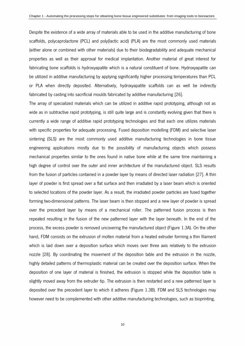
Chapter 1 - Automating the processing steps for obtaining bone tissue engineered substitutes: from imaging tools to bioreactors
10
Despite the existence of a wide array of materials able to be used in the additive manufacturing of bone
scaffolds, polycaprolactone (PCL) and poly(lactic acid) (PLA) are the most commonly used materials
(either alone or combined with other materials) due to their biodegradability and adequate mechanical
properties as well as their approval for medical implantation. Another material of great interest for
fabricating bone scaffolds is hydroxyapatite which is a natural constituent of bone. Hydroxyapatite can
be utilized in additive manufacturing by applying significantly higher processing temperatures than PCL
or PLA when directly deposited. Alternatively, hydroxyapatite scaffolds can as well be indirectly
fabricated by casting into sacrificial moulds fabricated by additive manufacturing [26].
The array of specialized materials which can be utilized in additive rapid prototyping, although not as
wide as in subtractive rapid prototyping, is still quite large and is constantly evolving given that there is
currently a wide range of additive rapid prototyping technologies and that each one utilizes materials
with specific properties for adequate processing. Fused deposition modelling (FDM) and selective laser
sintering (SLS) are the most commonly used additive manufacturing technologies in bone tissue
engineering applications mostly due to the possibility of manufacturing objects which possess
mechanical properties similar to the ones found in native bone while at the same time maintaining a
high degree of control over the outer and inner architecture of the manufactured object. SLS results
from the fusion of particles contained in a powder layer by means of directed laser radiation [27]. A thin
layer of powder is first spread over a flat surface and then irradiated by a laser beam which is oriented
to selected locations of the powder layer. As a result, the irradiated powder particles are fused together
forming two-dimensional patterns. The laser beam is then stopped and a new layer of powder is spread
over the precedent layer by means of a mechanical roller. The patterned fusion process is then
repeated resulting in the fusion of the new patterned layer with the layer beneath. In the end of the
process, the excess powder is removed uncovering the manufactured object (Figure 1.3A). On the other
hand, FDM consists on the extrusion of molten material from a heated extruder forming a thin filament
which is laid down over a deposition surface which moves over three axis relatively to the extrusion
nozzle [28]. By coordinating the movement of the deposition table and the extrusion in the nozzle,
highly detailed patterns of thermoplastic material can be created over the deposition surface. When the
deposition of one layer of material is finished, the extrusion is stopped while the deposition table is
slightly moved away from the extruder tip. The extrusion is then restarted and a new patterned layer is
deposited over the precedent layer to which it adheres (Figure 1.3B). FDM and SLS technologies may
however need to be complemented with other additive manufacturing technologies, such as bioprinting,

Chapter 1 - Automating the processing steps for obtaining bone tissue engineered substitutes: from imaging tools to bioreactors
11
Figure 1.3 – Schematic representation of the mode of operation of selective laser sintering A), fused deposition
modeling B) and bioprinting C).

Chapter 1 - Automating the processing steps for obtaining bone tissue engineered substitutes: from imaging tools to bioreactors
12
in order to replicate specific features contained into the bone tissue structure. Bioprinting results from
the extrusion of material from a nozzle but unlike fused deposition modelling it does not involve heating.
Therefore, the extrusion process can involve sensitive materials such as gels and cellular aggregates
[29]. Typically, the process is started with the patterned deposition of a gel filament which forms a
grooved layer. This gel layer then allows for further deposition of a second material which is composed
of small cellular aggregates. The deposition of those aggregates into the grooves formed by the gel layer
insures that the cellular aggregates are kept in their exact positions. This process is repeated layer over
layer generating three-dimensional shapes composed of cellular aggregates which during further
maturation fuse together and generate continuous masses of cells possessing a pre-determined shape
(Figure 1.3C). A particular application of bioprinting is in the formation of blood vessel networks
contained into bone. Blood vessel networks are flexible and delicate structures which possess
mechanical properties very different from the surrounding tissue. These structures have so far been
mimicked by applying gel-based or even scaffold-free printing technologies which are able to lay down
intricate patterns of cells which later generate vessel-like structures. An example of that is shown in a
work by Norotte et al. [30], where bioprinting was utilized to concomitantly lay down aggregates of
various cell types according to predefined patterns which during further maturation fused together and
generated stratified three-dimensional vessel-like structures. Furthermore, previous works show as well
that soft materials such as gels can be further integrated into the structure of more stiff thermoplastic
scaffolds resulting in scaffolds possessing optimal mechanical properties [31, 32]. By using a similar
strategy, and applying design principles mimicking the natural organization of blood vessels [33-35], the
concomitant integration of bioprinted blood vessels into the structure of more mechanically stable
scaffolds produced by technologies such as FDM or SLS would potentially enable the generation of
mechanically stable vascularized bone tissue substitutes (Figure 1.1B).
5. Culturing cells in 3D templates
Despite being highly labour intensive and expensive, static culture is still the most widely used cell
culture technique in tissue engineering strategies. This culturing technique is often characterized by
non-homogenous cell distribution, being the majority of seeded cells confined to the outer surfaces of
the scaffold, which in turn results in non-homogenous distribution of the in vitro-generated extracellular
matrix. Furthermore, static culturing conditions are far from mimicking the dynamic environment found
in vivo which is responsible for many signals/stimuli that trigger cell development. Dynamic cell culture
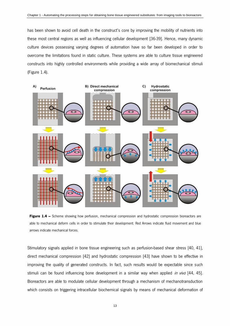
Chapter 1 - Automating the processing steps for obtaining bone tissue engineered substitutes: from imaging tools to bioreactors
13
has been shown to avoid cell death in the construct’s core by improving the mobility of nutrients into
these most central regions as well as influencing cellular development [36-39]. Hence, many dynamic
culture devices possessing varying degrees of automation have so far been developed in order to
overcome the limitations found in static culture. These systems are able to culture tissue engineered
constructs into highly controlled environments while providing a wide array of biomechanical stimuli
(Figure 1.4).
Stimulatory signals applied in bone tissue engineering such as perfusion-based shear stress [40, 41],
direct mechanical compression [42] and hydrostatic compression [43] have shown to be effective in
improving the quality of generated constructs. In fact, such results would be expectable since such
stimuli can be found influencing bone development in a similar way when applied in vivo [44, 45].
Bioreactors are able to modulate cellular development through a mechanism of mechanotransduction
which consists on triggering intracellular biochemical signals by means of mechanical deformation of
Figure 1.4 – Scheme showing how perfusion, mechanical compression and hydrostatic compression bioreactors are
able to mechanical deform cells in order to stimulate their development. Red Arrows indicate fluid movement and blue
arrows indicate mechanical forces.

Chapter 1 - Automating the processing steps for obtaining bone tissue engineered substitutes: from imaging tools to bioreactors
14
the cellular structure [46]. Perfusion bioreactors employ pumps to continuously perfuse culture medium
through the interconnected porous networks of cell-seeded scaffolds. Shear stress resulting from the
movement of fluid over the surface of cells in the scaffolds results in the deformation of the structure of
cells and triggers mechanotransductive downstream reactions (Figure 1.4A). Given their simplicity, flow
perfusion bioreactors enable seeding and culture of cells into scaffolds with a high degree of
automation. In a different way, bioreactors performing direct mechanical compression are inspired by
the mechanical compressive forces felt by tissues in their natural environment during movement. Cells
contained into porous scaffolds are stimulated by the deformation that occurs in the scaffold’s structure
during compression/relaxation (Figure 1.4B). Shear stress can as well occur as a result from the
movement of fluids from/to the interior of the scaffold’s pores during deformation. Finally, in hydrostatic
pressure bioreactors, mechanical forces act directly over the wall of cells contained into porous
scaffolds by means of a fluid. When the pressure of the fluid (culture medium) contained in the
bioreactor (and into the scaffold’s pores) is increased/decreased it acts upon the cellular wall by
causing a compression/relaxation deformation (Figure 1.4C). Apart from being able to simplify and
automate the process of construct culture, bioreactors in general show as well the potential to generate
constructs in a more standardized, traceable, cost-effective, safe and regulatory-compliant way [47, 48].
Bioreactors must also be versatile, being able to adapt to various kinds of constructs possessing
variable degrees of complexity and aimed at diverse applications. This is why bioreactors, as well as
their fabrication process, must be easily adjustable to specific conditions and requirements on the fly.
Recent work addressed this requirement by resorting to additive manufacturing not only to fabricate
scaffolds but as well to simultaneously fabricate their enclosing culture chamber [49]. In this way,
complex-shaped constructs could be produced to replicate the shape of CT-scanned bone parts while
contained into a culture chamber optimally designed for that specific construct (Figure 1.1C).
Another aspect which is important for the applicability of tissue engineering into the clinic is process
scalability. In a scenario of widespread adoption of tissue engineering-based therapies, significant
amounts of sufficiently large constructs would need to be simultaneously produced in order to fulfil
clinical demands (Figure 1.1D). Many scalable and modular systems have been developed to address
this requirement by resorting to various fabrication processes in order to enable the simultaneous
culture of multiple and/or large constructs [38, 50-52]. A specific application where this is already
visible (although usually at a smaller construct scale) is in the high throughput screening of biomaterials
where cells contained into multiple simplified 3D constructs are submitted to varying culture
environments in order to fully understand and optimize their development [53, 54].
Chapter 1 - Automating the processing steps for obtaining bone tissue engineered substitutes: from imaging tools to bioreactors
15
Such as the human body, bioreactors must as well be able to continuously sense and accordingly react
to all the events occurring in the construct and its surrounding environment during culture. Many kinds
of sensors and analytical techniques have been so far integrated into bioreactor-based procedures. The
most common ones are based on electrochemical and optical principles and are usually applied in
either an invasive, non-invasive or shunt configuration [55]. Some of them are commonly used in other
types of fully up-scaled cultures such as the culture of yeasts or bacterial microorganisms for mass
production of food and drug compounds as well as in clinical and physiological monitoring [56]. A very
interesting type of bioreactor with particular utility for bone tissue engineering is able to perform non-
invasive high resolution analysis of bone constructs under perfusion culture by means of micro-CT
scanning [57, 58]. In this way, tissue constructs do not need to be removed from its culture chamber
every time a scan is performed hence reducing human labour as well as minimizing the possibility of
contamination.
6. Implant
The most common tissue engineering strategies assume that in order to regenerate or replace a
damaged tissue, one must collect cells from the patient and then seed and culture them ex vivo onto a
material support in combination with biochemical factors in order to generate a construct which then
can be implanted back into the patient’s body through common surgical procedures. Despite the
popularity of ex vivo strategies, alternative tissue engineering strategies consider that tissue
replacements can be generated inside the patient’s own body by using the concept of “in vivo
bioreactors”. This strategy consists on the creation and manipulation of artificial spaces in the patient’s
body into which an external material can be inserted and cultured. In this strategy, the patient’s body
becomes the bioreactor since it dynamically provides all the necessary biomechanical and biochemical
conditions for cells directly recruited from the patient’s own body to generate a new tissue inside the “in
vivo bioreactor” [59-64].
Given the high complexity and sensitivity of the body, in vivo bioreactors can be considered the apex of
tissue culture since they are naturally capable of continuously sensing the changing needs required by a
developing tissue and accurately providing all the necessary biomechanical and biochemical signals. On
the other hand, this kind of strategy also shows evident disadvantages in comparison to ex vivo
strategies since it requires additional surgical procedures namely for the creation of the in vivo
bioreactor cavity as well as for the collection of the generated tissue to be applied into damaged sites.

Chapter 1 - Automating the processing steps for obtaining bone tissue engineered substitutes: from imaging tools to bioreactors
16
7. Off-the-shelf storage of tissue engineered constructs by cryopreservation
Given that tissue engineered products are expected to have a growing number of applications in the
regeneration of human tissues, and that their fabrication process can require long time spans [65-69],
resulting in excessively long incapacitation of patients, the ability to properly store large amounts of
these products for later off-the-shelf utilization is seen as a promising possibility but also as a
demanding challenge.
The utilization of cryopreservation has been evaluated as a solution for long term storage of such live
tissue substitutes [70-75]. Cryopreservation is based on the principle that chemical, biological and
physical processes are effectively “suspended” at cryogenic temperatures [76] and therefore becomes
more advantageous than commonly used preservation techniques, such as refrigeration or continuous
tissue culture, which show drawbacks such as limited shelf-life, high cost, risk of contamination and
genetic drift. Such strategy of cryopreserving tissue engineered substitutes would involve cells previously
seeded and cultured onto scaffolds. This would be a way to generate a reliable source of readily
available and ready to implant engineered constructs, greatly reducing the incapacitation time of
patients.
8. Concluding remarks and future directions
The automation of tissue engineering is becoming a reality. Important advancements in this area
allowed so far to mostly create and identify the basic enabling technologies necessary for the proper
development of this field. Nonetheless, and given the high complexity of bone tissue, it becomes
necessary to develop equally complex development strategies, but these must result in simpler
methodologies and technologies that enable automation and thus, easier processing into industrial
viable products that can reach large scale clinical applicability. The rapid development in computer and
automation technologies as well as the achievement of higher resolution powers in analysis and
fabrication processes increasingly enables tissue engineers to more closely mimic the complex and
highly dynamic environments found in native tissues. The convergence of these technologies allied to an
increasingly better understanding of the mechanisms at the basis of tissue development will in the
future allow for the generation of tissue replicas possessing similar or even improved features. Equally

Chapter 1 - Automating the processing steps for obtaining bone tissue engineered substitutes: from imaging tools to bioreactors
17
important is the training of highly skilled hybrid scientists capable of mastering and combining all the
involved technologies into generating mass produced, tailor-made, patient-specific solutions.
9. Acknowledgments
We would like to acknowledge the partial support by the European Network of Excellence
EXPERTISSUES (NMP3-CT-2004-500283). Pedro Costa would also like to acknowledge the Portuguese
Foundation for Science and Technology for his PhD grant (SFRH/BD/62452/2009).
10. References
1. Brooks PM. The burden of musculoskeletal disease - a global perspective. Clin
Rheumatol.25:778-81. 2006.
2. Giannoudis PV, Dinopoulos H, Tsiridis E. Bone substitutes: An update. Injury.36:20-7. 2005.
3. Desai BM. Osteobiologics. American journal of orthopedics (Belle Mead, NJ).36:8-11. 2007.
4. Damien CJ, Parsons JR. Bone-Graft and Bone-Graft Substitutes - a Review of Current
Technology and Applications. J Appl Biomater.2:187-208. 1991.
5. Quarto R, Mastrogiacomo M, Cancedda R, Kutepov SM, Mukhachev V, Lavroukov A, et al.
Repair of large bone defects with the use of autologous bone marrow stromal cells. New Engl J
Med.344:385-6. 2001.
6. Brun P, Dickinson SC, Zavan B, Cortivo R, Hollander AP, Abatangelo G. Characteristics of repair
tissue in second-look and third-look biopsies from patients treated with engineered cartilage:
relationship to symptomatology and time after implantation. Arthritis Res Ther.10. 2008.
7. Eaglstein WH, Falanga V. Tissue engineering and the development of Apligraf(R), a human skin
equivalent. Clin Ther.19:894-905. 1997.
8. Mason C. Automated tissue engineering: a major paradigm shift in health care. Medical device
technology.14:16-8. 2003.
9. Shefelbine SJ, Simon U, Claes L, Gold A, Gabet Y, Bab I, et al. Prediction of fracture callus
mechanical properties using micro-CT images and voxel-based finite element analysis. Bone.36:480-8.
2005.
10. Tuan HS, Hutmacher DW. Application of micro CT and computation modeling in bone tissue
engineering. Comput Aided Design.37:1151-61. 2005.
Chapter 1 - Automating the processing steps for obtaining bone tissue engineered substitutes: from imaging tools to bioreactors
18
11. Silva DN, De Oliveira MG, Meurer E, Meurer MI, Da Silva JVL, Santa-Barbara A. Dimensional
error in selective laser sintering and 3D-printing of models for craniomaxillary anatomy reconstruction. J
Cranio Maxill Surg.36:443-9. 2008.
12. Grayson WL, Frohlich M, Yeager K, Bhumiratana S, Chan ME, Cannizzaro C, et al. Engineering
anatomically shaped human bone grafts. Proceedings of the National Academy of Sciences of the
United States of America.107:3299-304. 2010.
13. Reiffel AJ, Kafka C, Hernandez KA, Popa S, Perez JL, Zhou S, et al. High-Fidelity Tissue
Engineering of Patient-Specific Auricles for Reconstruction of Pediatric Microtia and Other Auricular
Deformities. Plos One.8. 2013.
14. Kang TY, Kang HW, Hwang CM, Lee SJ, Park J, Yoo JJ, et al. The realistic prediction of oxygen
transport in a tissue-engineered scaffold by introducing time-varying effective diffusion coefficients. Acta
biomaterialia.7:3345-53. 2011.
15. Otsuki B, Takemoto M, Fujibayashi S, Neo M, Kokubo T, Nakamura T. Pore throat size and
connectivity determine bone and tissue ingrowth into porous implants: Three-dimensional micro-CT
based structural analyses of porous bioactive titanium implants. Biomaterials.27:5892-900. 2006.
16. Mavrogenis AF, Dimitriou R, Parvizi J, Babis GC. Biology of implant osseointegration. J
Musculoskel Neuron.9:61-71. 2009.
17. Eshraghi S, Das S. Micromechanical finite-element modeling and experimental characterization
of the compressive mechanical properties of polycaprolactone-hydroxyapatite composite scaffolds
prepared by selective laser sintering for bone tissue engineering. Acta biomaterialia.8:3138-43. 2012.
18. Hollister SJ, Levy RA, Chu TM, Halloran JW, Feinberg SE. An image-based approach for
designing and manufacturing craniofacial scaffolds. Int J Oral Max Surg.29:67-71. 2000.
19. Tellis BC, Szivek JA, Bliss CL, Margolis DS, Vaidyanathan RK, Calvert P. Trabecular scaffolds
created using micro CT guided fused deposition modeling. Mat Sci Eng C-Bio S.28:171-8. 2008.
20. Wettergreen MA, Bucklen BS, Starly B, Yuksel E, Sun W, Liebschner MAK. Creation of a unit
block library of architectures for use in assembled scaffold engineering. Comput Aided Design.37:1141-
9. 2005.
21. Chen Z, Su Z, Ma S, Wu X, Luo Z. Biomimetic modeling and three-dimension reconstruction of
the artificial bone. Comput Meth Prog Bio.88:123-30. 2007.
22. Yasar O, Lan SF, Starly B. A Lindenmayer system-based approach for the design of nutrient
delivery networks in tissue constructs. Biofabrication.1. 2009.

Chapter 1 - Automating the processing steps for obtaining bone tissue engineered substitutes: from imaging tools to bioreactors
19
23. Kermer C, Rasse M, Lagogiannis G, Undt G, Wagner A, Millesi W. Colour stereolithography for
planning complex maxillofacial tumour surgery. J Cranio Maxill Surg.26:360-2. 1998.
24. Chow J, Hui E, Lee PKM, Li W. Zygomatic implants - Protocol for immediate occlusal loading: A
preliminary report. J Oral Maxil Surg.64:804-11. 2006.
25. Ran W, Liu XZ, Guo B, Shu DL, Tan ZM. Removal of a foreign body from the skull base using a
customized computer-designed guide bar. J Cranio Maxill Surg.38:279-83. 2010.
26. Chu TMG, Halloran JW, Hollister SJ, Feinberg SE. Hydroxyapatite implants with designed
internal architecture. J Mater Sci-Mater M.12:471-8. 2001.
27. Williams JM, Adewunmi A, Schek RM, Flanagan CL, Krebsbach PH, Feinberg SE, et al. Bone
tissue engineering using polycaprolactone scaffolds fabricated via selective laser sintering.
Biomaterials.26:4817-27. 2005.
28. Zein I, Hutmacher DW, Tan KC, Teoh SH. Fused deposition modeling of novel scaffold
architectures for tissue engineering applications. Biomaterials.23:1169-85. 2002.
29. Jakab K, Norotte C, Marga F, Murphy K, Vunjak-Novakovic G, Forgacs G. Tissue engineering by
self-assembly and bio-printing of living cells. Biofabrication.2. 2010.
30. Norotte C, Marga FS, Niklason LE, Forgacs G. Scaffold-free vascular tissue engineering using
bioprinting. Biomaterials.30:5910-7. 2009.
31. Schuurman W, Khristov V, Pot MW, van Weeren PR, Dhert WJA, Malda J. Bioprinting of hybrid
tissue constructs with tailorable mechanical properties. Biofabrication.3. 2011.
32. Jetze V, Benjamin P, Thijs JB, Jelle B, Wouter JAD, Ferry PWM, et al. Biofabrication of multi-
material anatomically shaped tissue constructs. Biofabrication.5:035007. 2013.
33. Lemon G, Howard D, Tomlinson MJ, Buttery LD, Rose FRAJ, Waters SL, et al. Mathematical
modelling of tissue-engineered angiogenesis. Math Biosci.221:101-20. 2009.
34. Manoussaki D. A mechanochemical model of angiogenesis and vasculogenesis. Esaim-Math
Model Num.37:581-99. 2003.
35. Merks RMH, Koolwijk P. Modeling Morphogenesis in silico and in vitro: Towards Quantitative,
Predictive, Cell-based Modeling. Math Model Nat Pheno.4:149-71. 2009.
36. Bancroft GN, Sikavitsast VI, van den Dolder J, Sheffield TL, Ambrose CG, Jansen JA, et al. Fluid
flow increases mineralized matrix deposition in 3D perfusion culture of marrow stromal osteloblasts in a
dose-dependent manner. P Natl Acad Sci USA.99:12600-5. 2002.
37. Cartmell SH, Porter BD, Garcia AJ, Guldberg RE. Effects of medium perfusion rate on cell -
seeded three-dimensional bone constructs in vitro. Tissue Eng.9:1197-203. 2003.
Chapter 1 - Automating the processing steps for obtaining bone tissue engineered substitutes: from imaging tools to bioreactors
20
38. Grayson WL, Bhumiratana S, Cannizzaro C, Chao PHG, Lennon DP, Caplan AI, et al. Effects of
Initial Seeding Density and Fluid Perfusion Rate on Formation of Tissue-Engineered Bone. Tissue Eng Pt
A.14:1809-20. 2008.
39. Sikavitsas VI, Bancroft GN, Mikos AG. Formation of three-dimensional cell/polymer constructs
for bone tissue engineering in a spinner flask and a rotating wall vessel bioreactor. J Biomed Mater
Res.62:136-48. 2002.
40. Sikavitsas VI, Bancroft GN, Holtorf HL, Jansen JA, Mikos AG. Mineralized matrix deposition by
marrow stromal osteoblasts in 3D perfusion culture increases with increasing fluid shear forces.
Proceedings of the National Academy of Sciences of the United States of America.100:14683-8. 2003.
41. Goldstein AS, Juarez TM, Helmke CD, Gustin MC, Mikos AG. Effect of convection on
osteoblastic cell growth and function in biodegradable polymer foam scaffolds. Biomaterials.22:1279-
88. 2001.
42. Endres S, Kratz M, Wunsch S, Jones DB. Zetos: A culture loading system for trabecular bone.
Investigation of different loading signal intensities on bovine bone cylinders. J Musculoskel
Neuron.9:173-83. 2009.
43. Henstock JR, Rotherham M, Rose JB, El Haj AJ. Cyclic hydrostatic pressure stimulates
enhanced bone development in the foetal chick femur in vitro. Bone.53:468-77. 2013.
44. Srinivasan S, Weimer DA, Agans SC, Bain SD, Gross TS. Low-magnitude mechanical loading
becomes osteogenic when rest is inserted between each load cycle. J Bone Miner Res.17:1613-20.
2002.
45. Allison SJ, Folland JP, Rennie WJ, Summers GD, Brooke-Wavell K. High impact exercise
increased femoral neck bone mineral density in older men: A randomised unilateral intervention.
Bone.53:321-8. 2013.
46. Sikavitsas VI, Temenoff JS, Mikos AG. Biomaterials and bone mechanotransduction.
Biomaterials.22:2581-93. 2001.
47. Martin I, Smith T, Wendt D. Bioreactor-based roadmap for the translation of tissue engineering
strategies into clinical products. Trends Biotechnol.27:495-502. 2009.
48. Gardel LS, Serra LA, Reis RL, Gomes ME. Use of Perfusion Bioreactors and Large Animal
Models for Long Bone Tissue Engineering. Tissue Engineering Part B: Reviews. 2013.
49. Costa PF, Martins A, Vaquette C, Melchels FP, Neves NM, Gomes ME, et al. Bioreactor
composed of watertight chamber and internal matrix for the generation of cellularized medical implants.
2013.

Chapter 1 - Automating the processing steps for obtaining bone tissue engineered substitutes: from imaging tools to bioreactors
21
50. Koch MA, Vrij EJ, Engel E, Planell JA, Lacroix D. Perfusion cell seeding on large porous
PLA/calcium phosphate composite scaffolds in a perfusion bioreactor system under varying perfusion
parameters. J Biomed Mater Res A.95A:1011-8. 2010.
51. Janssen FW, van Dijkhuizen-Radersma R, Van Oorschot A, Oostra J, de Bruijn JD, Van
Blitterswijk CA. Human tissue-engineered bone produced in clinically relevant amounts using a semi-
automated perfusion bioreactor system: a preliminary study. J Tissue Eng Regen M.4:12-24. 2010.
52. Costa PF, Martins A, Neves NM, Gomes ME, Reis RL. Multichamber bioreactor with
bidirectional perfusion integrated in culture system for tissue engineering strategies. European Patent
Application 090098632009.
53. Rotenberg MY, Ruvinov E, Armoza A, Cohen S. A multi-shear perfusion bioreactor for
investigating shear stress effects in endothelial cell constructs. Lab on a Chip.12:2696-703. 2012.
54. Figallo E, Cannizzaro C, Gerecht S, Burdick JA, Langer R, Elvassore N, et al. Micro-bioreactor
array for controlling cellular microenvironments. Lab on a Chip.7:710-9. 2007.
55. Rolfe P. Sensing in tissue bioreactors. Meas Sci Technol.17:578-83. 2006.
56. Santoro R, Krause C, Martin I, Wendt D. On-line monitoring of oxygen as a non-destructive
method to quantify cells in engineered 3D tissue constructs. J Tissue Eng Regen M.6:696-701. 2012.
57. Porter BD, Lin ASP, Peister A, Hutmacher D, Guldberg RE. Noninvasive image analysis of 3D
construct mineralization in a perfusion bioreactor. Biomaterials.28:2525-33. 2007.
58. Hagenmuller H, Hitz M, Merkle HP, Meinel L, Muller R. Design and validation of a novel
bioreactor principle to combine online micro-computed tomography monitoring and mechanical loading
in bone tissue engineering. Rev Sci Instrum.81. 2010.
59. Holt GE, Halpern JL, Dovan TT, Hamming D, Schwartz HS. Evolution of an in vivo bioreactor. J
Orthop Res.23:916-23. 2005.
60. Han D, Dai K. Prefabrication of a Vascularized Bone Graft With Beta Tricalcium Phosphate
Using an In Vivo Bioreactor. Artificial Organs. 2013.
61. Stevens MM, Marini RP, Schaefer D, Aronson J, Langer R, Shastri VP. In vivo engineering of
organs: The bone bioreactor. Proceedings of the National Academy of Sciences of the United States of
America.102:11450-5. 2005.
62. Terheyden H, Knak C, Jepsen S, Palmie S, Rueger DR. Mandibular reconstruction with a
prefabricated vascularized bone graft using recombinant human osteogenic protein-1: an experimental
study in miniature pigs. Part 1: Prefabrication. Int J Oral Max Surg.30:373-9. 2001.

Chapter 1 - Automating the processing steps for obtaining bone tissue engineered substitutes: from imaging tools to bioreactors
22
63. Terheyden H, Warnke P, Dunsche A, Jepsen S, Brenner W, Palmie S, et al. Mandibular
reconstruction with prefabricated vascularized bone grafts using recombinant human osteogenic
protein-1: an experimental study in miniature pigs. Part II: Transplantation. Int J Oral Max Surg.30:469-
78. 2001.
64. Warnke PH, Springer ING, Wiltfang J, Acil Y, Eufinger H, Wehmoller M, et al. Growth and
transplantation of a custom vascularised bone graft in a man. Lancet.364:766-70. 2004.
65. Fleming JE, Jr., Cornell CN, Muschler GF. Bone cells and matrices in orthopedic tissue
engineering. Orthop Clin North Am.31:357-74. 2000.
66. Hutmacher DW. Scaffolds in tissue engineering bone and cartilage. Biomaterials.21:2529-43.
2000.
67. Kim BS, Mooney DJ. Development of biocompatible synthetic extracellular matrices for tissue
engineering. Trends Biotechnol.16:224-30. 1998.
68. Perka C, Sittinger M, Schultz O, Spitzer RS, Schlenzka D, Burmester GR. Tissue engineered
cartilage repair using cryopreserved and noncryopreserved chondrocytes. Clin Orthop Relat Res.245-54.
2000.
69. Vacanti CA, Bonassar LJ. An overview of tissue engineered bone. Clin Orthop Relat Res.S375-
81. 1999.
70. Miyoshi H, Ehashi T, Ohshima N, Jagawa A. Cryopreservation of Fibroblasts Immobilized Within
a Porous Scaffold: Effects of Preculture and Collagen Coating of Scaffold on Performance of Three-
Dimensional Cryopreservation. Artificial Organs.34:609-14. 2010.
71. Yin H, Cui L, Liu G, Cen L, Cao Y. Vitreous cryopreservation of tissue engineered bone
composed of bone marrow mesenchymal stem cells and partially demineralized bone matrix.
Cryobiology.59:180-7. 2009.
72. Rupf T, Ebert S, Lorenz K, Salvetter J, Bader A. Cryopreservation of Organotypical Cultures
Based on 3D Scaffolds. Cryoletters.31:157-68. 2010.
73. Bernemann I, Kuberka M, Glasmacher B. 71. Adapted freezing and thawing procedures to
improve the cryopreservation of cell seeded scaffolds. Cryobiology.53:397-8. 2006.
74. Kofron MD, Opsitnick NC, Attawia MA, Laurencin CT. Cryopreservation of tissue engineered
constructs for bone. Journal of Orthopaedic Research.21:1005-10. 2003.
75. Costa PF, Dias AF, Reis RL, Gomes ME. Cryopreservation of Cell/Scaffold Tissue-Engineered
Constructs. Tissue Eng Part C-Me.18:852-8. 2012.

Chapter 1 - Automating the processing steps for obtaining bone tissue engineered substitutes: from imaging tools to bioreactors
23
76. Karlsson JO, Toner M. Long-term storage of tissues by cryopreservation: critical issues.
Biomaterials.17:243-56. 1996.

25
Section II
Detailed description of experimental testing and materials


Chapter 2 - Materials and methods
27
Chapter 2
Materials and methods
This chapter provides a general overview and detailed information on all the techniques used and
biological assays performed under the scope of this thesis. Although described in the materials and
methods section of each experimental chapter, herein the objective is to contextualize and justify the
selection of materials and methodologies applied throughout the thesis and complement information
given on each chapter.
Chapter 2 - Materials and methods
28
1. Materials
Throughout the work described in this thesis various materials have been utilized for the development of
scaffolds. The selection of each material was performed according to the specific requirements of each
device and application to be addressed in each of the experimental chapters. Polycaprolactone is a very
commonly utilized and well accepted material in implantation-based biomedical applications either
alone, blended with other polymers or in a composite with ceramic materials. Poly(lactic) acid is an
equally common and accepted material in such applications with the additional advantage of also being
one of the most commonly utilized materials in additive manufacturing by fused deposition modelling.
Another advantage of these two materials is that their mechanical and biochemical properties can be
easily tailored to meet required properties. Another material commonly utilized in fused deposition
modelling is ABS, which, despite being more utilized in industrial applications, possesses the advantage
of being inert and so becoming suitable for the fabrication of non-implantable devices (in this case cell
culture chambers).
1.1. Polycaprolactone
Polycaprolactone (PCL) is a biodegradable polyester obtained by chemical synthesis from crude
oil and can be synthesized by a ring opening polymerization of a cylic lactone monomer. PCL is an
hydrophobic and semi-crystalline polymer with a melting point of around 60 °C and a glass transition
temperature of about -60 °C. Its degradation by hydrolysis of ester bonds in physiological conditions [1,
2] along with good biocompatibility and ability to form blends and copolymers have made it very
suitable for application as a biomaterial becoming approved by the Food and Drug Administration (FDA)
for use in the human body in forms such as drug delivery devices and sutures [3-5]. The medical grade
PCL used in this work was purchased from Lactel (USA) and was utilized in chapter 6 for producing
fiber meshes by melt electrospinning.
1.2. Polycaprolactone - β-tricalcium phosphate
β-tricalcium Phosphate (β-TCP) is a bioactive and biocompatible ceramic similar to the
amorphous inorganic phase of bone which can be produced synthetically by calcination of either
precipitated hydroxyapatite or a mixture of dicalcium phosphate dihydrate with precipitated

Chapter 2 - Materials and methods
29
hydroxyapatite [6]. It is degradable by osteoclastic activity, has the ability to bind directly to bone and is
osteoinductive while eliciting minimal immunologic reactions. β-TCP is commonly used in the form of
granules and blocks as a bone substitute. The integration of β-TCP and polymers such as
polycaprolactone into composite scaffolds is able to combine properties of both the polymer and the
ceramic resulting in enhanced mechanical, biocompatibility and osteoconductivity properties as well as
increased degradation rate [7]. Given the known osteoinductive properties of polycaprolactone - β-
tricalcium Phosphate, blends composed of medical grade PCL and 20% wt β-TCP were purchased from
Osteopore Inc. (Singapore) and were used in the work described in chapter 6 of this thesis for
producing 3D scaffolds by additive manufacturing.
1.3. Poly(lactic) acid
Poly(lactic) acid (PLA) is an hydrophobic aliphatic polyester belonging to the α-hydroxy group
which is among the most popular and most widely used materials in tissue engineering [8, 9]. It is
usually synthesized by ring-opening polymerization of the cyclic diester lactide [10]. PLA exists in either
isomeric forms D or L, or in its racimic form D,L. The PLLA form is the most commonly used since it is
preferentially metabolized in the body [11]. PLA is a degradable polymer which undergoes hydrolytic
scission to its monomeric form, lactic acid, which in turn is eliminated from the body by incorporation
into the tricarboxylic acid cycle. The principal elimination path for lactic acid is respiration, and it is
primarily excreted by the lungs as CO2 [12]. Such as PCL, PLA is among the few biodegradable
polymers which are approved by the FDA for human clinical use in the form of implantable materials
and/or devices. The commercially available PLA used in this work was Ingeo 4043D from NatureWorks
LLC (USA). Given the widespread use/study of PLA in biomedical applications, in particular for
replacing hard tissues such as bone, it was used in the works described in chapters 4 and 5 for
producing 3D scaffolds by additive manufacturing. Furthermore, PLA is one of the most commonly used
polymers in fused deposition modelling-based additive manufacturing.
1.4. Acrylonitrile butadiene styrene (ABS)
Acrylonitrile–butadiene–styrene (ABS) is a copolymer synthesized via graft copolymerization of styrene
and acrylonitrile monomers onto polybutadiene chains, which provides advantageous mechanical
properties, such as increased toughness and a higher impact and chemical resistance [13]. Given its

Chapter 2 - Materials and methods
30
characteristics, ABS has become a commonly used thermoplastic for making light, rigid, molded
everyday products. Moreover, ABS has also become the most commonly used polymer in additive
manufacturing given its high availability and low price. Due to its inert nature, ABS was used in the work
described in chapters 4 and 5 for additively manufacturing bioreactor chambers with optimized
geometries. The ABS utilized was purchased from Makerbot industries (USA).
1.5. Starch-Polycaprolactone blend (SPCL)
Starch is a polysaccharide carbohydrate made of glucose units joined together by glycosidic
bonds, which in turn are made of amylose, a linear polymer of several thousand glucose residues, and
amylopectin, a highly branched glucose-based polymer. Starch-based materials have attracted great
attention in tissue engineering applications due to the advantages of being non-cytotoxic, having good
mechanical properties and being processed by various methodologies as well as being able to reduce
costs and increase biodegradability when combined with various synthetic polymers [14-17].
Starch-based scaffolds obtained from a blend of corn starch and polycaprolactone (SPCL) have
for a long time been proposed in multiple studies from our group as candidates for bone tissue
engineering applications showing its suitability in terms of cell viability, proliferation and maturation of
osteoblastic cells or differentiation of bone marrow stromal cells [18, 19] as well as limited adverse
immune response when tested in vivo [20-22]. For these reasons, the 30:70 (wt.%) SPCL blend was
post-processed into either disk-shaped samples by injection molding or into fiber mesh structures by
melt-spinning and fiber bonding, in order to be utilized in the work described in chapter 7. The
polymeric blend was obtained from Novamont (Novara, Italy).
2. Fabrication of Culture devices and Scaffolds
2.1. Device Design
The general bioreactor design methodology employed in chapter 4 began with the generation of a 3D
numerical model for any tissue or organ by micro-computed tomography (micro-CT) imaging which was
then converted into a three-dimensional replica with pre-determined porosity. An outer shell, referred
herein as bioreactor chamber, possessing inlets/outlets was then designed around the replica in order
to manufacture, in one step, an anatomically shaped device comprising of an anatomically-optimized

Chapter 2 - Materials and methods
31
scaffold inserted into a customized bioreactor chamber. This allowed for the perfusion of the resulting
scaffold during in vitro culture, while better controlling the flow and shear stress in the system. In this
way, a 3 cm ovine tibia section was scanned by micro-CT to create a numerical 3D model which was
subsequently imported into 3Ds Max (Autodesk, USA) software. The 3D model was vertically re-oriented
and both extremities of the tibial model were trimmed for obtaining horizontal flat surfaces and resulted
in the final model having a total length of 2.5 cm. The 3D design tool, extrusion, was then used to
generate a shell wall around the lateral and top outer surfaces of the 3D model. The generated wall
was 1 mm thick and 1 mm-spaced from the 3D scaffold model’s outer surfaces. The top part of the
shell was converted to a tubular conical shape possessing a slope angle of 55o in order to be self-
supportive. This part of the shell was designed to enable an adequate fluid flow on the interior of the
device, and to provide sufficient space for containing extra culture medium. The top end of this conical
medium reservoir had a slope angle of 90o creating an inlet/outlet structure with an inner diameter of
2mm onto which tubing could be connected. The bottom corners of the chamber were additionally
chamfered by 2 mm with a slope angle of 45º to improve the hydrodynamic design. On the bottom
part of the device, a plate containing a 1 mm-wide mini channel was designed, allowing connectivity of
the centre of the plate to a lateral 2 mm diameter inlet/outlet. Furthermore, by using the same
extrusion design tool, a plain column was also generated for filling the empty space located in the
centre of the tibia-shaped model.
On the other hand, the device intended for high throughput screening applications utilized in chapter 5
was required to contain multiple samples for simultaneous testing and facilitated handling. The device
utilised in chapter 5 was designed to be modular and to allow for scaling-up according to the number of
scaffolds required for the experiment. The device was therefore designed to simultaneously
accommodate 8 cubical scaffolds (8 mm width) composed of 400 µm diameter struts horizontally
spaced by 1.5 mm in a 0-90 degree orientation. The device design was performed in 3Ds Max
(Autodesk, USA) software and consisted in building individualised bioreactor chambers by placing 1 mm
thick walls around each of the 8 scaffolds, which were organised in a rectangular 2 by 4 configuration.
The walls were positioned at 1 mm from the scaffolds and were 10 mm taller than the scaffolds in
order to create a reservoir for the culture medium. The top of every 4 chambers was covered by a
pyramidal structure ending by a 2 mm diameter outlet utilised for attaching sterile filters during
subsequent cell culture. A symmetrical mini-fluidic channel network was designed for homogenously
distributing the culture medium through the various individual chambers and allowing connectivity to a
lateral 2 mm diameter inlet/outlet.
Chapter 2 - Materials and methods
32
2.2. Additive manufacturing of devices and scaffolds by fused deposition modelling
(FDM)
Additive manufacturing is a highly automated layer-by-layer process which involves the
sequential building of layers of material by deposition of new layers of material on top of previously laid
layers of material. In tissue engineering, additive manufacturing is mainly used for the production of
scaffolds according to very defined structures generated through computer aided design (CAD) [23, 24].
In the work described in chapters 3, 4 and 5 of this thesis, the developed 3D CAD structures
were obtained either by simple design using geometrical shapes in the 3Ds Max (Autodesk, USA)
software or by means of the utilization of medical imaging data obtained by micro computerized
tomography analysis (Micro-CT).
The specific technology of fused deposition modelling, which was utilized in the work described
in this thesis, consists on the extrusion of molten material from a heated extruder forming a thin
filament which is laid down over a deposition surface which moves over three axis relatively to the
extrusion nozzle. By coordinating the movement of the deposition table and the extrusion in the nozzle,
highly detailed patterns of thermoplastic material can be created over the deposition surface. When the
deposition of one layer of material is finished, the extrusion is stopped while the deposition table is
slightly moved away from the extruder tip. The extrusion is then restarted and a new patterned layer is
deposited over the precedent layer to which it adheres.
Prior to the actual manufacturing, the 3D CAD models of the developed devices were first sliced
and converted to a G-Code file, which is the type of programming language commonly used to control
additive manufacturing machines. The open source software Reprap (Reprap Online Community) was
utilized in order to convert the plain volumes corresponding to the scaffolds designed in chapters 4 and
5 into porous structures by slicing into 0.27mm layers composed of deposition pathlines with a spacing
of 1.5mm. The volumes corresponding to the outer chamber devices designed in chapters 4 and 5
were sliced and converted to G-Code through the open source software ReplicatorG (ReplicatorG Online
Community) using 2 shells, a slice thickness of 0,27mm, an object infill of 100%, a feed rate of 20
mm/s and a travel feed rate of 55 mm/s as parameters. Both G-Codes generated through RepRap and
ReplicatorG were finally merged together generating one single G-Code file. The devices were then
manufactured using a dual extrusion Replicator (Makerbot Industries, USA) prototyping machine.
Poly(lactic) acid (PLA) Ingeo 4043D (NatureWorks LLC, USA) was used for building the porous scaffolds
Chapter 2 - Materials and methods
33
and acrylonitrile butadiene styrene (ABS) (Makerbot industries, USA) for building the enclosing devices.
The temperature used for fusing both materials in their corresponding nozzles was 220ºC. Both
materials were deposited during the same print job through coordinated and alternating operation of the
nozzles. The additive manufacturing by fused deposition modelling performed in the work described in
chapter 6 was similar to the one described above for the generation of scaffolds but instead utilizing a
PCL-β-TCP composite as deposition material.
2.3. Melt Electrospinning
Unlike randomly deposited fibers in solution electrospinning, molten polymers in melt
electrospinning possess higher viscosities and lower conductivities but can still be electrostatically
drawn over relatively large distances and their behavior and pathway can be controlled to a greater
extent [25]. Melt electrospun fibers tend as well to be larger than the solution electrospun fibers and as
a result generating meshes with greater pore size and interconnectivity facilitating cellular penetration.
The apparatus used in melt electrospinning apparatus is very similar to the ones utilized in
solution electrospinning, being essentially composed of a high voltage power supply with an electrode
connected to the needle of a syringe (containing the polymer) mounted onto a syringe pump and a
ground metallic collector placed at a defined distance from the tip of the metallic needle. The main
distinguishing characteristic of melt electrospinning is that the polymer contained into the syringe
reservoir is in a solid form (usually as pellet or powder) and in turn is heated by a thermal element
surrounding the syringe which in turn melts the polymer by heat transmission allowing it to be extruded
through the syringe needle. When the polymer exits the syringe needle, the electrostatic forces
generated by the power supply draw the polymer to the ground collector causing stretching and
narrowing of the resisting fiber. The polymer processed through melt electrospinning in the work
described in chapter 6 of this thesis (medical grade PCL from Lactel, (USA)) was electrospun using an
in-house melt electrospinning device. Medical grade pellets were loaded into a 2 mL syringe and
electrospun at a temperature of 80°C at a feed rate of 20 µL/h, at 7 kV and at a 4 cm tip to collector
distance. Circular membranes with roughly 8 mm diameter were produced by electrospinning the
molten PCL for periods of 4 min onto aluminum foil-covered glass slides placed over the collector. The
architectural and mechanical properties of melt electrospun meshes were found to be ideal for being
applied in the work described in chapter 6 since they would act as robust yet soft biomechanical
Chapter 2 - Materials and methods
34
supports for the deposition of several layers of cell sheets without inducing any disruptive damage to
those same cell sheets.
2.4. Biomimetic coating of the FDM scaffolds
In the early nineties Kokubo et al. developed a solution called Simulated Body Fluid (SBF)
which could be utilized for depositing biomimetic calcium phosphate (CaP) coatings on the surface of
devices and implants [26, 27]. This technique has demonstrated its efficacy at increasing bone related
gene expression in various cell types [28-32] and at enhancing ectopic bone formation in rat models
[33]. Given the osteoinductive properties of this kind of coating, the same was applied to the surface
modification of two types of scaffolds involved in the work described in chapters 5 and 6 of this thesis.
The PCL FDM scaffolds utilized in chapter 6 were submitted to a calcium phosphate coating
process by successive immersion into specific reagents and solutions. The procedure consisted of the
following steps: immersion in 100% ethanol for 15 minutes under vacuum, immersion in sodium
hydroxide 2 M for 30 min at 37ºC, multiple rinse-immersions in ultrapure water until a water pH of 7
was reached, immersion in a 10x simulated body fluid (SBF) solution for 30 min at 37ºC and
immersion in a 0.5 M sodium hydroxide solution for 30 min at 37ºC. Finally the coated scaffolds were
rinsed with ultrapure water and stored in a desiccator until use.
In chapter 5, a similar coating method was employed for improving the surface properties of
the utilized scaffolds. In this case however the utilized scaffolds were made of PLA and were contained
into an enclosed device requiring a slightly modified procedure. Given the hydrophobic nature of PLA
used for manufacturing the scaffolds, which could hinder appropriate and homogeneous fluid perfusion
through the device, an alkaline etching was performed using a 2M sodium hydroxide (NaOH) solution.
The devices were pre-wetted in 100% ethanol solution under vacuum for a period between 15 min and
one hour. Thereafter, the ethanol was removed and the sodium hydroxide solution was perfused though
the device until the bioreactor was entirely filled and 30 min vacuum treatment at room temperature
was performed prior to placing the device at 37°C for 60 min. Finally, the devices were washed four
times with distilled water prior to the further deposition of a calcium phosphate biomimetic coating on
the PLA filaments. The deposition of the calcium phosphate coating was performed by filling the
chambers with a total of 8 ml of 10x Simulated Body Fluid (SBF) solution at pH 6 for 30 min at 37ºC
and followed by perfusion with a 0.5 M sodium hydroxide solution for 30 min at 37ºC. Finally the
coated scaffolds were rinsed with ultrapure water and air-dried.
Chapter 2 - Materials and methods
35
2.5. Fiber bonding
Fiber bonding is a very simple and straightforward processing methodology which consists of binding
individual fibers, either woven or knitted, into three-dimensional patterns of variable pore size. The
advantageous characteristic features of fiber meshes produced in this way are a large surface area for
cell attachment and a good interconnectivity among pores that usually favors the flow of nutrients and
therefore enhances cellular survival and proliferation [34-37]. A drawback of these scaffolds, when
comparing to scaffolds fabricated by other methodologies such as additive manufacturing, is the
difficulty to accurately control their architecture and porosity [34, 36, 37].
The porous scaffolds utilized in the work described in chapter 7 were produced through a pre-
established fiber bonding methodology [38, 39]. Briefly, a selected amount of fibers obtained by melt
spinning was placed in a glass mould and heated in an oven at 150ºC. Immediately after removal of the
mould from the oven, the fibers were slightly compressed with a Teflon cylinder. After bonding, the fiber
meshes were cut into 8 mm diameter and 3.5–4 mm thick samples by punching.
2.6. Injection molding
In chapter 7 injection molding was employed to produce SPCL nonporous discs. This methodology has
been utilized for producing scaffolds for tissue engineering applications, however it has mostly been
explored in combination with blowing agents which, when exposed to high temperatures, expand and
form pores into the molded polymer and therefore generating porous structures [40, 41]. In the work
described in chapter 7, however, our aim was to obtain injection molded structures without any porosity
and therefore no blowing agent was used. These discs were produced in a Klockner Ferromatic FM-20
machine using a mould that allowed obtaining discs with 8 mm diameter and 3 mm thickness. The
produced injection molded discs were later seeded with cells and cryopreserved to assess the effect of
this process on the surface properties of the materials and also to compare with porous scaffolds that
underwent the same procedure, namely to analyze the effect of porosity in the maintenance of the
survival of seeded/cultured cells upon cryopreservation.

Chapter 2 - Materials and methods
36
3. Scaffolds Characterization
3.1. Morphological Characterization
3.1.1. Scanning Electron Microscopy
Scanning electron microscopy (SEM) is a commonly used microscopic method for analyzing the
morphology of materials and structures given its high magnifications capacity. SEM is mainly used for
studying the three-dimensional topography of specimens down to sub-micron scales. In order to
increase the degree of magnification, polymeric samples are usually coated with conductive materials
such as gold or carbon by sputtering prior to analysis.
SEM characterization was employed in all experimental chapters of this thesis, for assessment
of the morphology and porous architectures of the developed scaffolds and also for assessing the
interaction of cells with their surfaces. In the studies where materials and scaffolds were
seeded/cultured with cells (chapters 4 to 7).the resulting samples were removed from culture, washed
with PBS and fixed in 3% glutaraldehyde. Afterwards the cell-scaffolds samples were immersed in 0.1 M
cacodylate buffer, 1 % osmium tetroxide in cacodylate buffer, rinsed in ultrapure water and then
dehydrated by immersion into increasingly higher concentration ethanol solutions. Finally, samples were
immersed in hexamethyldisilazane for 60 min, air dried, mounted onto stubs and gold coated. Samples
were observed on a FEI Quanta 200 Environmental SEM operating at 10 kV.
3.1.2. Micro computerized tomography
Currently existing technologies for non-invasive imaging allow for body parts or whole bodies to
be analyzed without any damage to tissues themselves. Technologies such as micro computerized
tomography (micro-CT) enable the collection of data from damaged tissue sites which need to be
repaired. Given the high degree of resolution provided by such technologies it becomes possible to
obtain not only information related to the defect’s and organ’s outer shape but also information related
to their more complex inner porosity, density and micro structure.
Micro computerized tomography makes use of an X-ray source to obtain cross-sectional images
of three-dimensional objects which are then combined to reconstruct a three-dimensional numerical
model of the analyzed object [42].

Chapter 2 - Materials and methods
37
In the work described in chapters 4 to 6 of this thesis, samples were analyzed by Micro-CT
(µCT40, SCANCO Medical AG, Brüttisellen, Switzerland) at a resolution of 12 µm, a voltage of 55 kVp
and at a current of 175 µA. In chapter 7, a SkyScan 1072 equipment was used, where the x-ray source
was set up to 40KV, 248μA with a magnification of 23.29x and an exposure time of 1.8 seconds which
resulted in a resolution of about 11.32 μm/pixel. Three-dimensional images were reconstructed from
the scans by the micro-CT system software. In chapters 4 and 5, this analysis allowed to evaluate
characteristics such as the device’s inner architecture and the effect of post-treatment modification in
PLA scaffolds while in chapter 5 it allowed to assess the morphology and calculate both the volumes
and densities of de novo generated bone tissue in the biphasic scaffolds. In chapter 7, micro-ct was
mainly used to assess if the porosity of the scaffolds used was altered by cryopreservation.
3.1.3. Computational fluid flow modelling
Homogenous fluid velocities and absence of stagnant zones are among the main features
defining an optimal culture system which can greatly determine the fate of cultured cells and tissues.
The control over the fluid pattern within perfused scaffolds is essential for achieving efficient in vitro
culture conditions. Computational fluid dynamics is a mathematically generated simulation tool which is
able to predict the behavior of fluids with selected properties along spaces with predetermined sizes
and shapes.
Computational fluid dynamics was used to optimize the flow pattern in the culture chambers
developed under chapters 4 and 5. For this purpose, various chamber designs diverging in several
parameters were tested with regard to the homogeneity of the flow pattern. Given the high complexity of
the device’s architecture, simplified two-dimensional sections of the devices were created in Design
Modeler 13.0 (Ansys) software. The profile corresponding to the section of an 8 mm wide cubic porous
scaffold surrounded by a 10 mm wide bioreactor chamber was considered in chapter 5. On the other
hand, in chapter 4, a profile corresponding to a section of a tubular scaffold with a length of 2.5 cm, an
outer diameter of 13 mm and an inner diameter of 6 mm was considered. The thickness of the studied
simplified sections was 0.1 mm and the maximum face size of the generated model mesh was 2x10⁻⁴
mm. The fluid flow velocity profiles were calculated using Fluent 13.0 (Ansys, USA) software, within
Ansys Workbench 13.0 platform. The pressure at the device’s outlets was assumed to be zero and the
scaffold and the bioreactor chamber were considered rigid and impermeable. We assumed that the

Chapter 2 - Materials and methods
38
viscosity and the density of the culture media at 37°C were η = 1.45•10−3Pa.s) and (ρ = 1000
kg.m−3) respectively.
3.1.4. Atomic Force Microscopy (AFM)
Atomic force microscopy is a technique which allows to obtain very small surface roughness profiles in
the surface of samples by means of a cantilever probe. The surface roughness of the SPCL discs
utilized in chapter 7 was measured by AFM, in order to assess the effect of the cryopreservation
process in this surface property. AFM was not performed on the SPCL scaffolds utilized in that chapter
since their surfaces were not sufficiently flat for this methodology to be reliably employed. The analysis
was performed on 3 samples per study group/condition on at least three spots per sample using
tapping mode in a multimode scanning probe microscope (Veeco, USA) connected to a NanoScope III
(Veeco, USA) with non-contacting silicon nanoprobes (ca. 300 kHz, setpoint 2–3 V) (Nanosensors,
Switzerland). All images were fitted to a plane using the 1st degree flatten procedure included in
NanoScope software version 4.43r8.
3.2. Mechanical characterization
In chapter 7, SPCL scaffolds and discs were submitted to compression tests before and after
cryopreservation for determining their compressive modulus, using a universal tensile testing machine
(Instron 4505 Universal Machine). The aim was to assess the effect of cryopreservation over the
mechanical properties of the utilized scaffolds and discs. The tests were performed under compression
loading using a crosshead speed of 2 mm/min until 60% strain was reached. The compressive modulus
was determined in the most linear region of the stress–strain curve using the secant method. A total of
10 samples per study group/condition were used for this analysis.
3.3. X-Ray diffraction
X-ray diffraction is an important technique for qualitative and quantitative analyses as well as for
fundamental studies of the properties and structures of materials. The particularly useful feature of this
technique is that it enables the identification of specific compounds contained into samples.
Chapter 2 - Materials and methods
39
Furthermore, it is a nondestructive technique hence allowing to obtain large amounts of information
about relatively small material samples [43]. In a simplified way, x-ray diffraction acts by exposing
materials to x-ray beams. The analysis of the angle and intensity of resulting diffracted beams can then
be analyzed and a diffraction pattern obtained. The diffraction pattern of a pure material is unique
hence resulting as a fingerprint. By comparison with diffraction patterns stored into databases it
becomes then possible to identify the specific compounds composing a certain sample. This technique
was utilized in chapter 6 of this thesis to analyse the calcium phosphate layer deposited onto the
surface of the PCL-β-TCP scaffolds. Samples were characterised by using a PANalytical X’Pert MPD
Powder X-ray Diffractometer, a Cobalt anode and a 2 theta step size of 0.001.
4. Biological assays
4.1. Harvest, Isolation and culture of primary osteoblasts
Freshly isolated osteoblasts were used for the studies carried out in the chapters 4, 5 and 6,
aiming to assess the functionality of the developed devices for bone regeneration applications. The
primary osteoblasts cultures were as well isolated from different locations in the body according to the
bone tissue that they were intended to replace, namely from the hip in chapters 4 and 5 and from the
mandible in chapter 6.
In the work described in chapters 4 and 5, where materials under study targeted applications in
the replacement of long bones, human osteoblasts were collected from patients experiencing
reconstructive hip surgery. Ethics approval for the use of human osteoblasts in this experiment was
granted from The Prince Charles Hospital ethics committee (ethics clearance number: EC2310) and
Queensland University of Technology ethics committee (ethics clearance number 0600000232). The
osteoblasts were expanded in basal alpha MEM modified medium (Gibco, USA) supplemented with 10%
fetal calf serum and 1% penicillin/streptomycin and used at passage 2. When reaching confluence, the
cells were trypsinized for further seeding over scaffolds.
In the work described in chapter 6, where the material under study targeted the regeneration of
jaw bone, cells were isolated from compact bone samples collected under sterile conditions from the
mandible of Merino sheep (ovis aries). Animal ethics approval for this study was granted by the Animal
Ethics Committee of the Queensland University of Technology. This procedure was performed under
general anesthesia with a trephine drill (5 mm diameter). The extracted samples were then minced,
Chapter 2 - Materials and methods
40
washed with phosphate buffered saline (PBS) and vortexed 5 times. Bone samples were then incubated
with 10 mL of 0.25% trypsin/EDTA for 3 min at 37°C in a 5% CO2 atmosphere. After trypsin
inactivation, samples were washed once again with PBS and transferred in basal culture media (DMEM
containing 10% FBS, 1% of penicillin/streptomycin) into 175 cm2 tissue culture flasks. Outgrowth of
osteoblasts was observed after 5-7 days. Cells were expanded and used at the third passage (P3) for
seeding scaffolds.
4.2. Harvest, isolation and culture of primary periodontal ligament cells
In the study described in chapter 6, primary periodontal ligament cells were utilized,
considering the relevance of assessing the materials specifically designed for the regeneration of
periodontal ligament.
In this case, cells were isolated from two incisors teeth extracted from Merino sheep (ovis
aries). Animal ethics approval for this study was granted by the Animal Ethics Committee of the
Queensland University of Technology. The teeth were then placed into a 50 mL tube containing DMEM
with 2% penicillin/streptomycin and 4 µg/mL fungizone. The middle third of the periodontal ligament
(PDL) was subsequently gently removed from the root surface with a scalpel and further sectioned into
approximately 1x1 mm2 pieces. The PDL tissues were placed into a 25 cm2 culture flask which was left
standing upright in an incubator at 37°C and 5% CO2 atmosphere for 30 min to allow tissue adhesion.
After this incubation period, 3 mL of DMEM containing 10% FBS, 1% of penicillin/streptomycin and 0.1
µg/mL fungizone were added and the flask was carefully laid down in the incubator. The first media
change occurred 4 days post extraction. After one week of culture, cells started migrating outwards
from the PDL tissues and reached confluence after 2-3 weeks of culture. The cells were passaged using
0.25% trypsin and further expanded until P3.
4.3. Periodontal ligament cell sheets
Cell sheet technology consists on the generation of multicellular tissues without the utilization of
a support scaffold. Cells are typically cultured to near confluence onto temperature-responsive culture
surfaces which as a consequence of temperature change promote the detachment of cells. As a result,
the cultured cells which still maintain their cell-cell connections can be collected in the form of thin
sheets of cells. This technology has before been applied to the generation of periodontal ligament cell
Chapter 2 - Materials and methods
41
sheet by Akizuki et al. in order to form new cementum and promote periodontal attachment by placing
various periodontal cell sheets onto the surfaces of teeth roots [44]. However, this technology can be
simplified to a certain extent by replacing the temperature-responsive culture surface by simple culture
wells from which cell sheets naturally detach when sufficient maturity is reached. Therefore, in the work
described in chapter 6, periodontal ligament cells were seeded at 10,000 cells/cm2 in a 24-well plate.
The cells were cultured in osteogenic media and as the cell sheet matured (after 7 days of culture), it
started to contract and detach from the well. The cell sheets were then collected by direct application
onto the surface of melt electrospun meshes.
4.4. Harvest, Isolation and culture of goat bone marrow stromal cells
Stromal stem cells have become highly valued cell sources for cell-based therapeutics and
regenerative medicine [45]. This can be explained by their high potential of expansion and self-renewal
as well as their possible application in autologous tissue engineering strategies, which makes them
more desirable than many other cell sources. Furthermore, when cultured with appropriated
supplemented culture media and specific environments, stromal stem cells can be differentiated into a
wide variety of tissues such as bone, cartilage, fat, muscle and tendon.
In chapter 7, bone marrow stromal cells were harvested from goats (GBMSC) given the
similarity of such animal model to humans in terms of metabolism and dimensions. GBMSCs were
harvested from the iliac crest of adult goats and isolated as described elsewhere [46] and then
expanded in low-glucose Dulbecco’s modified essential medium (DMEM; Sigma Chemical Co., St.
Louis, MO, USA) supplemented with 1% antibiotic/antimycotic (Sigma) and 10% fetal bovine serum
(FBS; Sigma). When confluence was reached, cells were trypsinized and ressuspended (at passage 4).
4.5. Perfusion culture
Perfusion bioreactors are able to improve mass transfer at the interior of three-dimensional
scaffolds. This type of bioreactor uses a pump to perfuse medium continuously through the
interconnected porous network of seeded scaffolds. The fluid path must be confined so as to ensure the
flow path is through the scaffold, rather than around the edges. The perfusion bioreactor offers
enhanced transport of nutrients because it allows medium to be transported through the interconnected
pores of the scaffolds. Besides cell culture, flow perfusion bioreactors can also be used for seeding cells
Chapter 2 - Materials and methods
42
into scaffolds. A variety of scaffolds can be effectively and reproducibly seeded in an automated and
controlled process using this straightforward concept into a simply designed bioreactor. Additionally,
perfusion seeding can be readily integrated into a perfusion bioreactor system capable of automatically
performing both seeding and subsequent culture of the construct. Stimulatory signals such as shear
stress applied by bioreactors have shown to be effective in improving the quality of generated constructs
[47, 48] given their similarity to stimuli which are naturally applied to cells and tissues in vivo [49, 50].
Perfusion cell culture was employed in the work described in chapters 4 and 5 and took place
over up to 6 weeks in a bi-directional perfusion mode into the specifically designed culture devices
described in section 2. To this end, a 1ml sterile syringe mounted on a multi-syringe adapter placed on
an Aladdin syringe pump (World Precision Instruments, USA) was connected to the device’s medium
inlet using sterile silicone tubing. The devices (each with a dedicated syringe) were simultaneously
cultured in this system. The devices were first sterilized by perfusion with 50% ethanol solution for 20
minutes and dried in a sterile hood for 2 hours. The devices were then manually filled with basal
medium and bi-directionally perfused overnight at a flow rate of 0.4 ml/min and flow direction inversion
every 100 seconds using the syringe system. This hydration step aimed at promoting the pre-adsorption
of proteins to the scaffold’s surfaces and hence facilitating subsequent cell attachment. In order to
ensure the sterility of the device over the culture period while still allowing gas exchange with the
incubator’s environment, a 0.2 µm pore size filter (13 mm diameter) (Pall, USA) was connected to the
outlet positioned at the top of the device. Cell suspensions were injected into the devices through
silicone tubes. The devices were bidirectionally perfused for 24 hours at a flow rate of 0.4 ml/min in
order to allow cell attachment. The perfusion direction was automatically inverted every 100 seconds
utilizing an external microcontroller connected to the syringe pump. After 24 hours, the culture medium
was replaced by fresh medium and the flow rate was increased to 0.8 ml/min whereas the flow
inversion frequency was reduced to 50 seconds. The medium was changed weekly until scaffolds
collection. According to the performed fluid flow modelling studies, the resulting local fluid flow rate was
in agreement with optimal flow rates reported in other studies [51, 52].
4.6. Confocal microscopy
Confocal microscopy allows to selectively control the depth of field eliminating out-of-focus
information and enables to collect serial optical sections from thick specimens. Furthermore, sequential
imaging can be applied to samples stained with specific agents which allow to distinguish elements of

Chapter 2 - Materials and methods
43
the samples such as cells and tissues. In this way, confocal microscopy is a valuable tool for analyzing
three-dimensional constructs since it allows to obtain high resolution 3D representations of irregularly
shaped samples composed of differentially stained elements.
In chapters 4 to 6 of this thesis, the morphology, orientation and viability of cells located onto
the surface of scaffolds were assessed by confocal laser microscopy using a confocal microscope (SP5,
Leica). According to the specific features to be analyzed, different staining procedures were employed.
For assessing cellular morphology and orientation, samples were washed in PBS and fixed
overnight in 4% (w/v) paraformaldehyde (PFA)/PBS. Samples were then washed in PBS and
permeabilized with 0.2 % Triton X100/PBS for precisely 5 minutes and again washed twice with PBS. F-
actin filaments and nuclei were then stained for 45 minutes with 0.8 U/mL rhodamine 415-conjugated
phalloidin and 5 μg/mL 4′-6-diamidino-2-phenylindole (DAPI) respectively in PBS. Immunofluorescence
was visualized and z-stacks acquired.
When constructs were analyzed for assessing cellular viability a live/dead assay was employed.
For this purpose, the constructs were washed twice in PBS, incubated for 5 min at 37ºC in PBS
containing 0.67 µg/ml fluorescein diacetate (FDA) and 5µg/ml propidium iodide (PI) (both Invitrogen)
and washed again in PBS. A semi-quantitative analysis of the cellular viability was also performed using
the ImageJ software to quantify living cells and dead cells (in different colors) from the images obtained
by confocal laser microscopy. A total of seven images from multiple areas of the constructs were
captured and analyzed for each time point.
4.7. Metabolic activity staining (MTT)
MTT staining is a very straightforward colorimetric method which allows to qualitatively analyze
the metabolic activity, and indirectly the viability of cells in culture. This method is based on the
utilization of yellow 3-(4,5-Dimethylthiazol-2-yl)-2,5-diphenyltetrazolium bromide (MTT) which is reduced
to purple formazan in the mitochondria of living cells. This reduction takes place only when
mitochondrial reductase enzymes are active, and therefore the color change observed in cells can be
directly related to their metabolic activity and viability.
In chapters 4 and 5, metabolically active cells were visualized by using a 1mg/ml 3-(4,5-
dimethylthiazol-2-yl)-2,5-diphenyltetrazolium bromide (MTT) solution. Following collection, constructs
were washed in PBS and then immersed into MTT solution for 30 minutes. A total of seven images from
multiple areas of the constructs were captured and analyzed for each time point. Images showing
Chapter 2 - Materials and methods
44
purple cells onto the surface of scaffolds were captured by a digital camera mounted on an Eclipse
TS100 microscope (Nikon, Tokyo, Japan).
4.8. Metabolic activity quantification (MTS assay)
In chapter 7, cellular viability was quantitatively assessed by the MTS, 3-(4,5-dimethylthiazol-2-yl)-5-(3-
carboxymethoxyphenyl)-2-(4-sulfophenyl)-2H-tetrazolium, assay (Promega, Madison, USA). Briefly, this
assay is based on the bioreduction of a tetrazolium compound, 3-(4,5-dimethylthiazol-2-yl)-5-(3-
carboxymethoxyphenyl)-2-(4-sulfofenyl)-2H-tetrazolium (MTS), into a brown formazan product that is
soluble in water. This conversion is accomplished by the production of nicotinamide adenine
dinucleotide phosphate (NADPH) or nicotinamide adenine dinucleotide (NADH) by the dehydrogenase
enzymes existing in metabolically active cells. The absorbance relative to the quantity of formazan
product is directly proportional to the number of living cells in culture, and was measured at 490 nm in
a microplate reader (Bio-Tek, model Synergie HT; USA). Culture medium without FBS and phenol red
was mixed with MTS in a ratio of 5:1 and added to wells containing the constructs to be analyzed. The
constructs were incubated in this solution for 3 hours at 37ºC in a 5% CO2 atmosphere. After the
incubation period, the optical density (OD) was read in a microplate reader (Bio-Tek, Synergie HT, USA)
at 490 nm. A total of 9 samples per study group/condition were analyzed being measurements made
in triplicate. The obtained results were normalized to the surface area of each type of sample used
(discs or scaffolds).
4.9. Cell proliferation assay
Cell proliferation is usually assessed by quantifying the synthesis of DNA at different time points
during a certain culture period. In the work described in chapters 4 to 7 of this thesis, cell proliferation
was quantified by the total amount of double-stranded DNA (dsDNA) using an ultrasensitive fluorescent
nucleic acid stain, during the culturing periods. Quant-iT™ PicoGreen® dsDNA reagent was selected for
this assay since it enables to quantify as little as 25 pg/mL of dsDNA (50 pg dsDNA in a 2 mL assay
volume) with a standard spectrofluorometer and fluorescein excitation and emission wavelengths.
Additionally, dsDNA can be quantified in the presence of equimolar concentrations of ssDNA and RNA
with minimal effect on the quantitative results obtained.
Chapter 2 - Materials and methods
45
Briefly, after collection of the samples and freezing at -80 °C for at least 48 hours, the analyzed
constructs were placed in 1.5 mL Eppendorf tubes containing 500 µL of Proteinase K (Invitrogen)
(Proteinase K/phosphate buffered EDTA (PBE) 0.5 mg/ml), at 60°C for 12 hours. The solution was
thereafter diluted at a ratio of 1/50 in Phosphate Buffered EDTA PBE, and 100 μL was aliquoted in
triplicates into black 96-well plates, and 100 µL of PicoGreen (P11496, Invitrogen) working solution was
added. After 5 min incubation in the dark, the fluorescence (excitation 485 nm, emission 520 nm) was
measured using a fluorescence plate reader (Benchmark PlusTM microplate spectrophotometer, BIO
RAD). A standard curve of known λ DNA concentrations ranging from 10 ng/ml to 1 µg/mL was used
to calculate the final DNA content of the sample.
4.10. Alkaline Phosphatase Quantification (ALP)
Alkaline phosphatase is a cell surface protein bound to the plasma membrane through
phosphatidylinositol phospholipid complexes whose high activity is associated with the active formation
of mineralized matrix, in particular during bone healing. ALP activity is also a commomly used marker
of the osteogenic phenotype both in primary osteoblasts and differentiating stem cells. In chapter 6 of
this thesis, ALP activity was measured from the media in triplicate at different time-points (2, 4 and 6
weeks) after a 24 hours release period. Briefly, samples were first immersed for 5 min in DMEM
without phenol red and this was repeated three times. They were then transferred to a new 24-well
plate and 1000 µL of this media was added before the samples were placed back in the incubator for
precisely 24 hours. ALP activity was measured using a SigmaFASTTM kit, as per the manufacturer’s
instructions. 100 µL of p-Nitrophenyl phosphate (which is hydrolysed by the alkaline phosphatase
produced by the cells) in Tris-base buffer was added to 100 µL of the culture media in a 96-well plate,
and incubated at 37°C and 5% CO2 for another 24 hours. At the end of the second incubation period,
the plate was brought back to ambient temperature (20 °C) for 5 min and the absorbance was read at
405 nm using a plate reader (Benchmark PlusTM microplate spectrophotometer, BIO RAD). The ALP
absorbance was normalized by the DNA content of each sample.
5. In vivo model
The performance of a biphasic scaffold in achieving periodontal regeneration including
simultaneous bone, periodontal ligament and cementum regeneration was assessed ectopically in a rat

Chapter 2 - Materials and methods
46
model, under chapter 6. The osteoblast loaded scaffolds were cultured for 6 weeks and then 3
previously cultured PDL ligament cell sheets were placed onto the PCL mesh comprising the
periodontal compartment. The following sections describe the preparation of the implant and surgical
implantation procedure.
5.1. Dentin slices and scaffold assembly
In order to simulate the interaction of the PDL compartment with teeth, dentin slices were
attached to the periodontal side of the biphasic constructs. To do so, one millimeter thick dentin slices
were prepared from sheep teeth and adjusted to the size of the biphasic scaffolds. The assembly of the
biphasic scaffolds onto dentin blocks was performed under sterile conditions and sutures were used to
keep the biphasic scaffold on top of the dentin slice. Thereafter the samples were immersed in media
for 2 hours in order to allow for cell sheet adhesion onto the dentin surface. Notches on the dentin
slides were created in order to prevent the sutures from sliding off, thus ensuring high stability of the
scaffold.
5.2. Subcutaneous implantation into nude rats
Ideally, models for studying new tissue engineering strategies should be based on the target
tissue to be restored. However, in order to reduce the variables involved in the process as well as the
number of tested animals, simpler models are usually adopted. The animal model utilized in the in vivo
study described in chapter 6 - rats – is relatively easy to maintain and handle as well as less expensive
than other larger models. Furthermore, the performed subcutaneous implantations enabled the
implantation of multiple constructs into a reduced number of animals.
For performing this study, animal ethics approval for the use of athymic nude rats was granted
by the Animal Ethics Committee of Griffith University. Five 8-week old male rats (Animal Resources
Centre, Canning Vale, WA, Australia) were used. The animals were anaesthetized with isoflurane. Six
small incisions were made longitudinally along the central line of the shaved dorsal area, approximately
2 cm apart, and subcutaneous pockets were made with surgical scissors. Six different groups of
biphasic scaffolds were implanted. Biphasic scaffolds combined with three cell sheet (n=5) or without
cell sheet (n=5), biphasic scaffold with osteoblasts cultured in basal media (n=5) or in osteogenic media
(n=5), CaP-coated scaffold with osteoblasts cultured in basal media (n=5) or in osteogenic media (n=5)
Chapter 2 - Materials and methods
47
were implanted for 8 weeks. Each individual pocket held one scaffold and the incisions were closed with
surgical sutures. The animals were sacrificed after eight weeks and the implants were retrieved and
fixed in 4% paraformaldehyde in PBS at pH 7.4 for further analysis.
5.3. Histological analysis of implanted constructs
In order to study the morphology of the constructs subcutaneously implanted into rats in
chapter 6, samples were decalcified in 10% EDTA at pH 7.4 for 3 months at 4 °C with a weekly change
of solution and subsequently embedded in paraffin. Sections near the central area of the implants were
used for the haematoxylin and eosin (H&E) and immunological stainings.
6. Seeding, cryopreservation and thawing of cell-seeded porous scaffolds and nonporous
discs
In chapter 7, In order to compare the effect of cryopreservation on different structures seeded with
cells, special measures were taken in the seeding procedure. Given the difference in surface area
available for cell attachment in the scaffolds and discs utilized in chapter 7, two different cellular
concentrations were prepared for seeding in each kind of structure, namely one cell suspension to seed
5x10⁵ cells in 300 µl volumes, for the scaffolds, and another in order to seed 1x10⁵ cells in volumes of
200 µl onto the surface of SPCL discs. The rationale used for the cell seeding density used in this work
was based in previously performed studies [46] which showed that a ratio of 5:1 was appropriate for
being able to seed a similar amount of these cells per surface area in both porous and nonporous
scaffolds and allowing for the formation of extracellular matrix and osteoblastic differentiation. All the
scaffolds/discs were placed in 24 well non-adherent plates in order to perform the seeding. After
seeding, these samples were carefully transferred into the incubator and left there for three hours,
before adding 1,5 ml of DMEM basal medium. The samples were cultured for 7 days, being the
medium changed every 2 or 3 days. Scaffolds and discs without cells were kept in the same conditions
to be used as experimental controls.
After 7 days of culture, half of the previously seeded constructs, as well as unseeded scaffolds and
discs, were collected for characterization assays, namely MTS, DNA quantification, SEM, micro-CT and
mechanical analysis while the other half of the constructs was cryopreserved, along with some more
unseeded scaffolds and discs. For the cryopreservation step, a cryopreservative solution composed of
Chapter 2 - Materials and methods
48
DMSO and FBS was used for suspending the seeded and unseeded scaffold and discs. The
concentration of DMSO to use in the cryoprotective solution was determined by estimating the amount
of cells in the scaffolds after 7 days of culture, using data obtained in previous studies [53]. A period of
7 days of cryopreservation was chosen taking into consideration previous studies performed in the field
which state that the duration of the storage in liquid nitrogen (-196oC) has a negligible impact on
constructs. Those studies used even shorter cryopreservation periods (less than one day) [54].Thus, for
each million of cells, a 10% concentration of DMSO was added to the cryopreservative solution. All
seeded and unseeded scaffolds and discs were suspended in cryoprotective solution inside standard
cryovials and placed inside a Statebourne Biosystem 24 cryogenic tank. After 7 days of
cryopreservation, the constructs and unseeded scaffolds/discs were removed from the cryogenic tank
and partially thawed in a 37ºC waterbath, removed from the cryovials and placed in 24 well non-
adherent plates. To each sample, a volume of cold DMEM basal medium with 20% FBS was added. The
samples were further cultured for 9 days being the medium changed every 2 or 3 days in order to allow
cells to recover from the cryopreservation step. Cells alone and tissues that are submitted to
cryopreservation always require a certain time to recover. Studies found in the literature have shown
that, after thawing, cellular viability tends to decrease for a period of at least 7 days before stabilizing
[55]. This recovery culture period also allowed for a more prolonged and more efficient leaching of
toxic DMSO’s residues, in particular from the porous constructs. The recovery culture period was not
prolonged for longer than 9 days since the strategy involved in a medically oriented usage of these
constructs would consist of applying these constructs into tissue defects as quickly as possible after
thawing in order to reduce patient’s immobilization time.
After each culturing period, the collected cell-seeded cells/scaffolds samples were washed at least twice
with 1ml of sterile PBS. In the case of the cells/scaffolds constructs to be used in DNA quantifications,
each sample was transferred to a sterile tube with 1ml of ultra-pure water. After this procedure, the
tubes with samples were kept at a temperature of -80ºC until further analysis, namely MTS, DNA
quantification, SEM, micro-CT and mechanical analysis, which were performed following the procedures
described in the previous sections..
7. Statistical Analysis
Statistical Analysis was performed in all the experimental chapters of this thesis using
GraphPad Prism software (version 5.00 for Windows). The statistical analysis was performed using a

Chapter 2 - Materials and methods
49
Shapiro-Wilk normality test and one-way ANOVA followed by a Tukey HSD post-hoc test. p< 0.05 was
considered as statistically significant.
8. References
1.Pitt, C.G., et al., Aliphatic Polyesters .2. The Degradation of Poly(Dl-Lactide), Poly(Epsilon-
Caprolactone), and Their Copolymers Invivo. Biomaterials, 1981. 2(4): p. 215-220.
2.Tsuji, H. and Y. Ikada, Blends of aliphatic polyesters .2. Hydrolysis of solution-cast blends from poly(L-
lactide) and poly(epsilon-caprolactone) in phosphate-buffered solution. Journal of Applied Polymer
Science, 1998. 67(3): p. 405-415.
3.Bezwada, R.S., et al., Monocryl(R) Suture, a New Ultra-Pliable Absorbable Monofilament Suture.
Biomaterials, 1995. 16(15): p. 1141-1148.
4.Darney, P.D., et al., Clinical-Evaluation of the Capronor Contraceptive Implant - Preliminary-Report.
American Journal of Obstetrics and Gynecology, 1989. 160(5): p. 1292-1295.
5.Allen, C., et al., Polycaprolactone-b-poly(ethylene oxide) copolymer micelles as a delivery vehicle for
dihydrotestosterone. Journal of Controlled Release, 2000. 63(3): p. 275-286.
6.Bohner, M., Calcium orthophosphates in medicine: from ceramics to calcium phosphate cements.
Injury-International Journal of the Care of the Injured, 2000. 31: p. S37-S47.
7.Lam, C.X.F., S.H. Teoh, and D.W. Hutmacher, Comparison of the degradation of polycaprolactone
and polycaprolactone-(beta-tricalcium phosphate) scaffolds in alkaline medium. Polymer International,
2007. 56(6): p. 718-728.
8.Agrawal, C.M. and R.B. Ray, Biodegradable polymeric scaffolds for musculoskeletal tissue
engineering. Journal of Biomedical Materials Research, 2001. 55(2): p. 141-150.
9.Athanasiou, K.A., G.G. Niederauer, and C.M. Agrawal, Sterilization, toxicity, biocompatibility and
clinical applications of polylactic acid polyglycolic acid copolymers. Biomaterials, 1996. 17(2): p. 93-
102.
10.Gilding, D.K. and A.M. Reed, Biodegradable Polymers for Use in Surgery - Polyglycolic-Poly(Actic
Acid) Homopolymers and Copolymers .1. Polymer, 1979. 20(12): p. 1459-1464.
11.Gunatillake, P.A., R. Adhikari, and N. Gadegaard, Biodegradable synthetic polymers for tissue
engineering. European Cells and Materials, 2003. 5: p. 1-16.

Chapter 2 - Materials and methods
50
12.Brady, J.M., et al., Resorption Rate, Route of Elimination, and Ultrastructure of Implant Site of
Polylactic Acid in Abdominal-Wall of Rat. Journal of Biomedical Materials Research, 1973. 7(2): p. 155-
166.
13.Pisuttisap, A., et al., ABS modified with hydrogenated polystyrene-grafted-natural rubber. Journal of
Applied Polymer Science, 2013. 129(1): p. 94-104.
14.Bastioli, C., et al., Physical State and Biodegradation Behavior of Starch-Polycaprolactone Systems.
Journal of Environmental Polymer Degradation, 1995. 3(2): p. 81-95.
15.Koenig, M.F. and S.J. Huang, Biodegradable Blends and Composites of Polycaprolactone and Starch
Derivatives. Polymer, 1995. 36(9): p. 1877-1882.
16.Vikman, M., et al., Morphology and enzymatic degradation of thermoplastic starch-polycaprolactone
blends. Journal of Applied Polymer Science, 1999. 74(11): p. 2594-2604.
17.Yavuz, H. and C. Babac, Preparation and biodegradation of starch/polycaprolactone films. Journal
of Polymers and the Environment, 2003. 11(3): p. 107-113.
18.Gomes, M.E., et al., Starch-poly(epsilon-caprolactone) and starch-poly(lactic acid) fibre-mesh
scaffolds for bone tissue engineering applications: structure, mechanical properties and degradation
behaviour. Journal of Tissue Engineering and Regenerative Medicine, 2008. 2(5): p. 243-252.
19.Gomes, M.E., et al., Effect of flow perfusion on the osteogenic differentiation of bone marrow stromal
cells cultured on starch-based three-dimensional scaffolds. Journal of Biomedical Materials Research
Part A, 2003. 67A(1): p. 87-95.
20.Marques, A.P., R.L. Reis, and J.A. Hunt, An in vivo study of the host response to starch-based
polymers and composites subcutaneously implanted in rats. Macromolecular Bioscience, 2005. 5(8):
p. 775-785.
21.Santos, T.C., et al., Vascular Endothelial Growth Factor and Fibroblast Growth Factor-2 Incorporation
in Starch-Based Bone Tissue-Engineered Constructs Promote the In Vivo Expression of
Neovascularization Mediators. Tissue Engineering Part A, 2013. 19(7-8): p. 834-848.
22.Santos, T.C., et al., In vivo short-term and long-term host reaction to starch-based scaffolds. Acta
Biomaterialia, 2010. 6(11): p. 4314-4326.
23.Peltola, S.M., et al., A review of rapid prototyping techniques for tissue engineering purposes. Annals
of Medicine, 2008. 40(4): p. 268-280.
24.Yeong, W.Y., et al., Rapid prototyping in tissue engineering: challenges and potential. Trends in
Biotechnology, 2004. 22(12): p. 643-652.
Chapter 2 - Materials and methods
51
25.Brown, T.D., P.D. Dalton, and D.W. Hutmacher, Direct Writing By Way of Melt Electrospinning.
Advanced Materials, 2011. 23(47): p. 5651-+.
26.Kokubo, T., et al., Ca, P-rich layer formed on high-strength bioactive glass-ceramic A-W. Journal of
Biomedical Materials Research, 1990. 24(3): p. 331-343.
27.Kokubo, T., H. Kushitani, and S. Sakka, Solutions able to reproduce in vivo surface-structure
changes in bioactive glass-ceramic A-W3. Journal of Biomedical Materials Research, 1990. 24: p. 721-
734.
28.Al-Munajjed, A.A., et al., Development of a biomimetic collagen-hydroxyapatite scaffold for bone
tissue engineering using a SBF immersion technique. Journal of Biomedical Materials Research - Part B
Applied Biomaterials, 2009. 90(2): p. 584-591.
29.Arafat, M.T., et al., Biomimetic composite coating on rapid prototyped scaffolds for bone tissue
engineering. Acta Biomaterialia. 7(2): p. 809-820.
30.Araujo, J.V., et al., Surface controlled biomimetic coating of polycaprolactone nanofiber meshes to
be used as bone extracellular matrix analogues. Journal of Biomaterials Science, Polymer Edition,
2008. 19(10): p. 1261-1278.
31.Liu, Y., et al., Influence of calcium phosphate crystal assemblies on the proliferation and osteogenic
gene expression of rat bone marrow stromal cells. Biomaterials, 2007. 28(7): p. 1393-1403.
32.Lu, Z., et al., Bone biomimetic microenvironment induces osteogenic differentiation of adipose
tissue-derived mesenchymal stem cells. Nanomedicine: Nanotechnology, Biology and Medicine, 1999.
8(4): p. 507-515.
33.Vaquette, C., et al., Ectopic bone formation in tissue–engineered calcium phosphate coated
polymeric construct: effect of coating and culture conditions. Biomaterials, 2013. to be submitted.
34.Thomson, R.C., et al., Biodegradable polymer scaffolds to regenerate organs. Biopolymers Ii, 1995.
122: p. 245-274.
35.Langer, R., Selected advances in drug delivery and tissue engineering. Journal of Controlled Release,
1999. 62(1-2): p. 7-11.
36.Lu, L.C. and A.G. Mikos, The importance of new processing techniques in tissue engineering. Mrs
Bulletin, 1996. 21(11): p. 28-32.
37.Maquet, V. and R. Jerome, Design of macroporous biodegradable polymer scaffolds for cell
transplantation. Porous Materials for Tissue Engineering, 1997. 250: p. 15-42.
38.Mendes, S.C., et al., Evaluation of two biodegradable polymeric systems as substrates for bone
tissue engineering. Tissue Eng, 2003. 9 Suppl 1: p. S91-101.
Chapter 2 - Materials and methods
52
39.Gomes, M.E., et al., Influence of the porosity of starch-based fiber mesh scaffolds on the
proliferation and osteogenic differentiation of bone marrow stromal cells cultured in a flow perfusion
bioreactor. Tissue Eng, 2006. 12(4): p. 801-809.
40.Gomes, M.E., et al., A new approach based on injection moulding to produce biodegradable starch-
based polymeric scaffolds: morphology, mechanical and degradation behaviour. Biomaterials, 2001.
22(9): p. 883-889.
41.Neves, N.M., A. Kouyumdzhiev, and R.L. Reis, The morphology, mechanical properties and ageing
behavior of porous injection molded starch-based blends for tissue engineering scaffolding. Materials
Science & Engineering C-Biomimetic and Supramolecular Systems, 2005. 25(2): p. 195-200.
42.Ho, S.T. and D.W. Hutmacher, A comparison of micro CT with other techniques used in the
characterization of scaffolds. Biomaterials, 2006. 27(8): p. 1362-1376.
43. Ryland, A.L., X-ray diffraction. Journal of Chemical Education, 1958. 35(2): p. 80.
44.Akizuki, T., et al., Application of periodontal ligament cell sheet for periodontal regeneration: a pilot
study in beagle dogs. Journal of Periodontal Research, 2005. 40(3): p. 245-251.
45.Satija, N.K., et al., Mesenchymal stem cells: Molecular targets for tissue engineering. Stem Cells
and Development, 2007. 16(1): p. 7-23.
46.Rodrigues, M.T., et al., Tissue-engineered constructs based on SPCL scaffolds cultured with goat
marrow cells: functionality in femoral defects. Journal of Tissue Engineering and Regenerative Medicine,
2011. 5(1): p. 41-49.
47.Sikavitsas, V.I., et al., Mineralized matrix deposition by marrow stromal osteoblasts in 3D perfusion
culture increases with increasing fluid shear forces. Proceedings of the National Academy of Sciences of
the United States of America, 2003. 100(25): p. 14683-14688.
48.Goldstein, A.S., et al., Effect of convection on osteoblastic cell growth and function in biodegradable
polymer foam scaffolds. Biomaterials, 2001. 22(11): p. 1279-1288.
49.Srinivasan, S., et al., Low-magnitude mechanical loading becomes osteogenic when rest is inserted
between each load cycle. Journal of Bone and Mineral Research, 2002. 17(9): p. 1613-1620.
50.Allison, S.J., et al., High impact exercise increased femoral neck bone mineral density in older men:
A randomised unilateral intervention. Bone, 2013. 53(2): p. 321-328.
51.Alvarez-Barreto, J., et al., Flow Perfusion Improves Seeding of Tissue Engineering Scaffolds with
Different Architectures. Annals of Biomedical Engineering, 2007. 35(3): p. 429-442.
Chapter 2 - Materials and methods
53
52.Goncalves, A., et al., Effect of flow perfusion conditions in the chondrogenic differentiation of bone
marrow stromal cells cultured onto starch based biodegradable scaffolds. Acta Biomaterialia, 2011.
7(4): p. 1644-1652.
53.Gomes, M.E., et al., Effect of flow perfusion on the osteogenic differentiation of bone marrow stromal
cells cultured on starch-based three-dimensional scaffolds. J Biomed Mater Res A, 2003. 67(1): p. 87-
95.
54.Wen, F., et al., Vitreous cryopreservation of nanofibrous tissue-engineered constructs generated
using mesenchymal stromal cells. Tissue Engineering - Part C: Methods, 2009. 15(1): p. 105-114.
55.Lübke, C., et al., Cryopreservation of Artificial Cartilage: Viability and Functional Examination after
Thawing. Cells Tissues Organs, 2001. 169(4): p. 368-376.


55
Section III
Experimental

Chapter 3 - Bioreactor composed of watertight chamber and internal matrix for the generation of
cellularized medical implants
57
Chapter 3
Bioreactor composed of watertight chamber and internal matrix for the generation of
cellularized medical implants
Abstract
The present invention relates to a bioreactor for the generation of medical implants which comprises an
external chamber, which can be unicompartmented 1 (preferably possessing two tubular structures 8)
or multicompartmented, and watertight containing in its interior one or more matrices 7, the
bioreactor’s internal matrices 7 and external chamber 1 being simultaneously manufactured, preferably
through a rapid prototyping process; and also characterized by an external chamber 1 possessing a
shape adapted to the shape of the implant to be cellularized (internal matrix) enabling a greater
efficiency in the cellular colonization and culture of the implant, and by the implants being removed
from the inside of the bioreactor by cutting the external chamber 1 in locations defined by grooves 9
right before implantation, allowing a greater sterility of the implant.
This chapter is based on the following publication:
Costa P.F., Martins A., Vaquette C., Melchels F.P., Neves N.M., Gomes M.E., Hutmacher D.W., Reis
R.L., Bioreactor composed of watertight chamber and internal matrix for the generation of cellularized
medical implants. World Patent Application WO 2013/103306 A1.

Chapter 3 - Bioreactor composed of watertight chamber and internal matrix for the generation of
cellularized medical implants
58
1. Object of the invention
The present invention relates to a bioreactor composed of a watertight chamber and one or more
matrices contained in its interior, which are simultaneously manufactured, whose matrix can be bi-
dimensional or three-dimensional, with variable porosity and delineated by simple or complex shapes, is
capable of supporting the seeding and culture of cells for, after removal of the watertight chamber,
originating cellularized medical implants for the replacement/regeneration of animal or human tissues
or organs previously damaged by trauma or disease.
2. State of the art
In the replacement or regeneration of tissues or organs after physical damage caused by trauma or
disease auto-, alio- or xenografts are currently used in clinical practice. However, these medical grafts
have limitations such as the low availability of healthy tissue, immunocompatibility problems or cross
infection between different animal species. To overcome these restrictions on its use in the current
clinic practice, Tissue Engineering emerged as a promising alternative. This strategy includes the
development of bi- or three-dimensional porous matrices that support cellular colonization and culture,
the ex vivo culture of cells and the presence of growth factors that induce cellular growth and/or
differentiation. These factors may be used independently, in groups of two or three in order to allow
tissue regeneration.
Being the development of bi- or three-dimensional porous matrices a key step in the success of a Tissue
Engineering strategy, these matrices must comprise a set of physicochemical properties (e.g. porosity,
interconnectivity, roughness, surface area, mechanical properties, hydrophilicity) that allow cellular
adhesion, migration, proliferation and differentiation. The maintenance of cells in culture within these bi-
or three-dimensional porous matrices can be achieved through the use of static or dynamic culture
systems. It has been demonstrated that the culture of cells in an appropriate biochemical environment
and in the presence of mechanical stimuli may promote the generation of cellularized medical implants.
Therefore, there is a great interest to replicate in vitro the physiological environment of a target tissue,
through the use of dynamic simulation biomechanics systems, scientifically known as bioreactors .
These bioreactors not only provide the cells in culture within bi- or three-dimensional porous matrices
with equal concentrations of nutrients and oxygen, but also allow the removal of byproducts resulting

Chapter 3 - Bioreactor composed of watertight chamber and internal matrix for the generation of
cellularized medical implants
59
from their metabolic activity. Besides these features, bioreactors also allow a more uniform colonization
of the bi- or three-dimensional porous matrices by the cells. Therefore, these dynamic culture systems
constitute a better quantitative control method over the parameters of cell culture, and can provide an
unlimited number of cellularized medical implants.
The present invention aims at the development of cellularized medical implants with improved
biomechanical properties, by developing methods of cellular colonization and culture on bi- or three-
dimensional porous matrices. Implicit is the development of a bioreactor which contains, in itself, one
or more bi- or three-dimensional porous matrices, allowing minimal handling of the cellularized medical
implant (s) in order to minimize the risk of contamination during ex vivo cell culture.
3. Description of the invention
The present invention refers to a bioreactor which can be utilized in the colonization and culture of cells
into support matrices contained into their interior, originating cellularized medical implants for the
substitution/regeneration of animal or human tissues or organs, such as bone, cartilage, skin and
muscle.
The bioreactor is mainly composed of one or more matrices, with variable porosity, three-dimensional or
bi-dimensional, contained into a unicompartmented or multicompartmented watertight chamber.
The culture chamber as well as the matrix contained in its interior are simultaneously manufactured
through a rapid prototyping process, from one or multiple materials. These materials can be
biodegradable or not, inert or not, polymeric or composite, transparent, translucent or opaque, such as
polycaprolactone (PCL) , polylactic acid (PLA) or polyglycolic acid (PGA) .
During the manufacture of the bioreactor and its internal matrix an extra water-soluble support material
can be used, which is as well deposited during the rapid prototyping process. This material acts only as
a support for the deposition of the deposited material or materials during the manufacture of the
chamber and its matrix, being afterwards removed by immersion into water or aqueous solution .
Chapter 3 - Bioreactor composed of watertight chamber and internal matrix for the generation of
cellularized medical implants
60
The architecture of the chamber and its internal matrix should preferably be designed to be self-
supportive, not being necessary the utilization of an additional support material.
The chambers and their inner matrices can be sterilized by several methods according to the materials
utilized. They can be sterilized by immersion into ethanol, by exposure to ultraviolet radiation or
exposure to ethylene oxide, in case none of the utilized materials show any adverse reactivity, or even
by autoclaving, when the utilized materials are sufficiently stable when exposed to high temperatures.
In case the external chamber is prototyped from one or more transparent or translucid materials it
becomes even possible to analyze its interior by optical means. In case the internal matrix is also
prototyped from transparent or translucid materials the interior of the internal matrix can also be
analyzed by optical means.
In order to improve the performance of the internal matrix contained into the chamber it is possible to
perform coatings of its surfaces by filling or perfusing the interior of the chamber, through the internal
matrix, with solutions or gases able to generate those coatings.
The internal matrix can be designed using as an initial reference simple shapes such as cuboid,
cylindrical, tubular or other shapes, or as well from complex shapes obtained from the analysis of
tissues or organs by means of computerized tomography or magnetic resonance techniques.
The design of the external chamber is performed having as initial reference the shape of the internal
matrix and by extrusion of its external surfaces.
To the external chamber' s design are added at least two tubular structures which are intended to
connect the interior of the chamber to the exterior and allowing the entry and exit of fluids and/or gases
from/to the interior of the chamber. The location of these tubular structures should be determined
taking into account the best possible efficiency in draining the fluids inserted into the chamber as well
as the improvement of the fluid flow dynamic into the chamber.
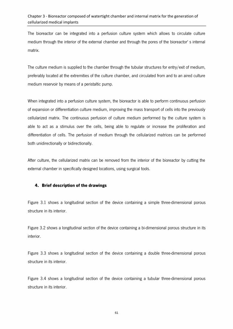
Chapter 3 - Bioreactor composed of watertight chamber and internal matrix for the generation of
cellularized medical implants
61
The bioreactor can be integrated into a perfusion culture system which allows to circulate culture
medium through the interior of the external chamber and through the pores of the bioreactor' s internal
matrix.
The culture medium is supplied to the chamber through the tubular structures for entry/exit of medium,
preferably located at the extremities of the culture chamber, and circulated from and to an aired culture
medium reservoir by means of a peristaltic pump.
When integrated into a perfusion culture system, the bioreactor is able to perform continuous perfusion
of expansion or differentiation culture medium, improving the mass transport of cells into the previously
cellularized matrix. The continuous perfusion of culture medium performed by the culture system is
able to act as a stimulus over the cells, being able to regulate or increase the proliferation and
differentiation of cells. The perfusion of medium through the cellularized matrices can be performed
both unidirectionally or bidirectionally.
After culture, the cellularized matrix can be removed from the interior of the bioreactor by cutting the
external chamber in specifically designed locations, using surgical tools.
4. Brief description of the drawings
Figure 3.1 shows a longitudinal section of the device containing a simple three-dimensional porous
structure in its interior.
Figure 3.2 shows a longitudinal section of the device containing a bi-dimensional porous structure in its
interior.
Figure 3.3 shows a longitudinal section of the device containing a double three-dimensional porous
structure in its interior.
Figure 3.4 shows a longitudinal section of the device containing a tubular three-dimensional porous
structure in its interior.
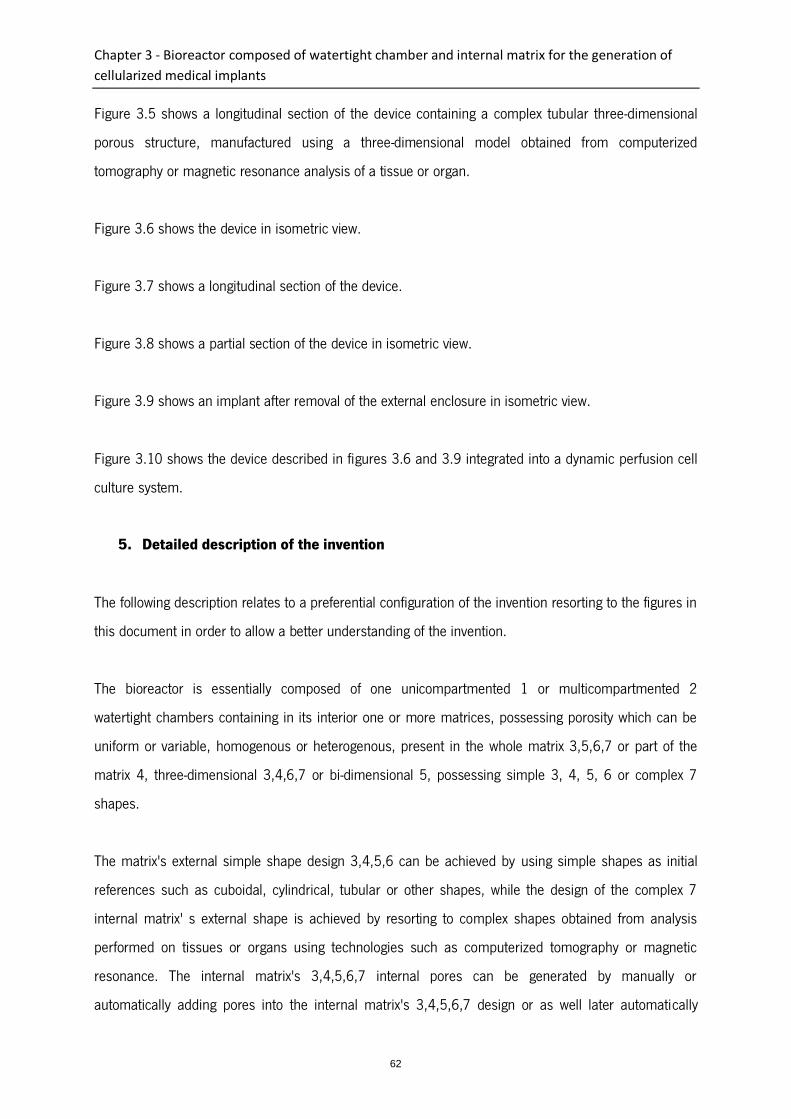
Chapter 3 - Bioreactor composed of watertight chamber and internal matrix for the generation of
cellularized medical implants
62
Figure 3.5 shows a longitudinal section of the device containing a complex tubular three-dimensional
porous structure, manufactured using a three-dimensional model obtained from computerized
tomography or magnetic resonance analysis of a tissue or organ.
Figure 3.6 shows the device in isometric view.
Figure 3.7 shows a longitudinal section of the device.
Figure 3.8 shows a partial section of the device in isometric view.
Figure 3.9 shows an implant after removal of the external enclosure in isometric view.
Figure 3.10 shows the device described in figures 3.6 and 3.9 integrated into a dynamic perfusion cell
culture system.
5. Detailed description of the invention
The following description relates to a preferential configuration of the invention resorting to the figures in
this document in order to allow a better understanding of the invention.
The bioreactor is essentially composed of one unicompartmented 1 or multicompartmented 2
watertight chambers containing in its interior one or more matrices, possessing porosity which can be
uniform or variable, homogenous or heterogenous, present in the whole matrix 3,5,6,7 or part of the
matrix 4, three-dimensional 3,4,6,7 or bi-dimensional 5, possessing simple 3, 4, 5, 6 or complex 7
shapes.
The matrix's external simple shape design 3,4,5,6 can be achieved by using simple shapes as initial
references such as cuboidal, cylindrical, tubular or other shapes, while the design of the complex 7
internal matrix' s external shape is achieved by resorting to complex shapes obtained from analysis
performed on tissues or organs using technologies such as computerized tomography or magnetic
resonance. The internal matrix's 3,4,5,6,7 internal pores can be generated by manually or
automatically adding pores into the internal matrix's 3,4,5,6,7 design or as well later automatically
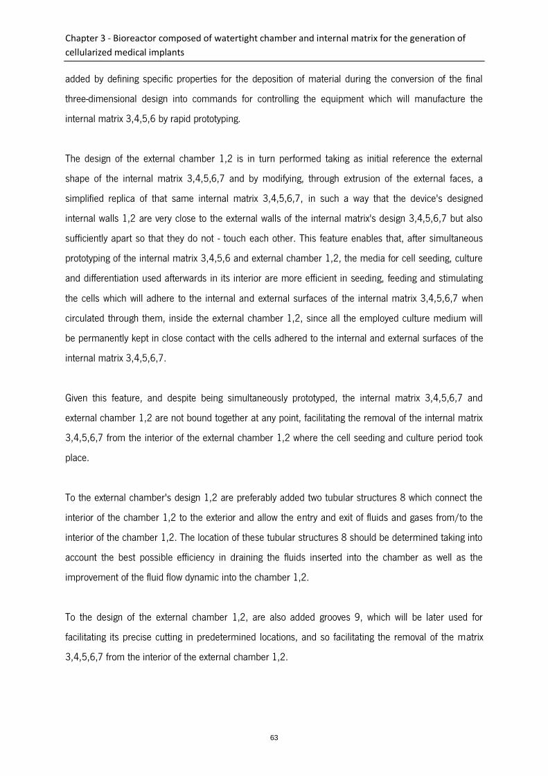
Chapter 3 - Bioreactor composed of watertight chamber and internal matrix for the generation of
cellularized medical implants
63
added by defining specific properties for the deposition of material during the conversion of the final
three-dimensional design into commands for controlling the equipment which will manufacture the
internal matrix 3,4,5,6 by rapid prototyping.
The design of the external chamber 1,2 is in turn performed taking as initial reference the external
shape of the internal matrix 3,4,5,6,7 and by modifying, through extrusion of the external faces, a
simplified replica of that same internal matrix 3,4,5,6,7, in such a way that the device's designed
internal walls 1,2 are very close to the external walls of the internal matrix's design 3,4,5,6,7 but also
sufficiently apart so that they do not - touch each other. This feature enables that, after simultaneous
prototyping of the internal matrix 3,4,5,6 and external chamber 1,2, the media for cell seeding, culture
and differentiation used afterwards in its interior are more efficient in seeding, feeding and stimulating
the cells which will adhere to the internal and external surfaces of the internal matrix 3,4,5,6,7 when
circulated through them, inside the external chamber 1,2, since all the employed culture medium will
be permanently kept in close contact with the cells adhered to the internal and external surfaces of the
internal matrix 3,4,5,6,7.
Given this feature, and despite being simultaneously prototyped, the internal matrix 3,4,5,6,7 and
external chamber 1,2 are not bound together at any point, facilitating the removal of the internal matrix
3,4,5,6,7 from the interior of the external chamber 1,2 where the cell seeding and culture period took
place.
To the external chamber's design 1,2 are preferably added two tubular structures 8 which connect the
interior of the chamber 1,2 to the exterior and allow the entry and exit of fluids and gases from/to the
interior of the chamber 1,2. The location of these tubular structures 8 should be determined taking into
account the best possible efficiency in draining the fluids inserted into the chamber as well as the
improvement of the fluid flow dynamic into the chamber 1,2.
To the design of the external chamber 1,2, are also added grooves 9, which will be later used for
facilitating its precise cutting in predetermined locations, and so facilitating the removal of the matrix
3,4,5,6,7 from the interior of the external chamber 1,2.
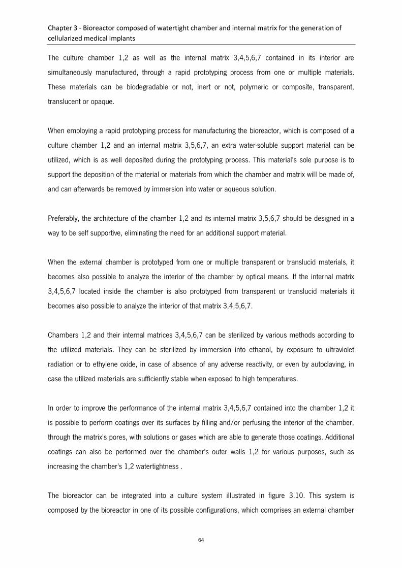
Chapter 3 - Bioreactor composed of watertight chamber and internal matrix for the generation of
cellularized medical implants
64
The culture chamber 1,2 as well as the internal matrix 3,4,5,6,7 contained in its interior are
simultaneously manufactured, through a rapid prototyping process from one or multiple materials.
These materials can be biodegradable or not, inert or not, polymeric or composite, transparent,
translucent or opaque.
When employing a rapid prototyping process for manufacturing the bioreactor, which is composed of a
culture chamber 1,2 and an internal matrix 3,5,6,7, an extra water-soluble support material can be
utilized, which is as well deposited during the prototyping process. This material's sole purpose is to
support the deposition of the material or materials from which the chamber and matrix will be made of,
and can afterwards be removed by immersion into water or aqueous solution.
Preferably, the architecture of the chamber 1,2 and its internal matrix 3,5,6,7 should be designed in a
way to be self supportive, eliminating the need for an additional support material.
When the external chamber is prototyped from one or multiple transparent or translucid materials, it
becomes also possible to analyze the interior of the chamber by optical means. If the internal matrix
3,4,5,6,7 located inside the chamber is also prototyped from transparent or translucid materials it
becomes also possible to analyze the interior of that matrix 3,4,5,6,7.
Chambers 1,2 and their internal matrices 3,4,5,6,7 can be sterilized by various methods according to
the utilized materials. They can be sterilized by immersion into ethanol, by exposure to ultraviolet
radiation or to ethylene oxide, in case of absence of any adverse reactivity, or even by autoclaving, in
case the utilized materials are sufficiently stable when exposed to high temperatures.
In order to improve the performance of the internal matrix 3,4,5,6,7 contained into the chamber 1,2 it
is possible to perform coatings over its surfaces by filling and/or perfusing the interior of the chamber,
through the matrix's pores, with solutions or gases which are able to generate those coatings. Additional
coatings can also be performed over the chamber's outer walls 1,2 for various purposes, such as
increasing the chamber's 1,2 watertightness .
The bioreactor can be integrated into a culture system illustrated in figure 3.10. This system is
composed by the bioreactor in one of its possible configurations, which comprises an external chamber
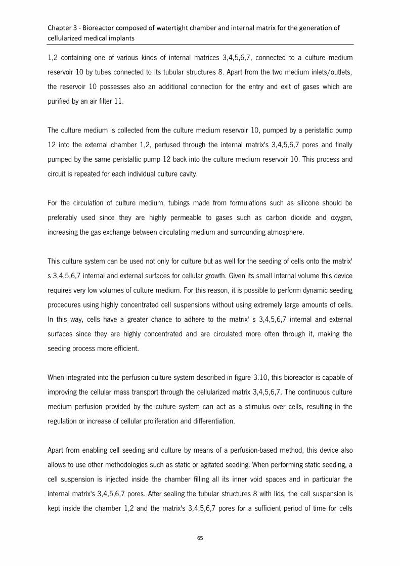
Chapter 3 - Bioreactor composed of watertight chamber and internal matrix for the generation of
cellularized medical implants
65
1,2 containing one of various kinds of internal matrices 3,4,5,6,7, connected to a culture medium
reservoir 10 by tubes connected to its tubular structures 8. Apart from the two medium inlets/outlets,
the reservoir 10 possesses also an additional connection for the entry and exit of gases which are
purified by an air filter 11.
The culture medium is collected from the culture medium reservoir 10, pumped by a peristaltic pump
12 into the external chamber 1,2, perfused through the internal matrix's 3,4,5,6,7 pores and finally
pumped by the same peristaltic pump 12 back into the culture medium reservoir 10. This process and
circuit is repeated for each individual culture cavity.
For the circulation of culture medium, tubings made from formulations such as silicone should be
preferably used since they are highly permeable to gases such as carbon dioxide and oxygen,
increasing the gas exchange between circulating medium and surrounding atmosphere.
This culture system can be used not only for culture but as well for the seeding of cells onto the matrix'
s 3,4,5,6,7 internal and external surfaces for cellular growth. Given its small internal volume this device
requires very low volumes of culture medium. For this reason, it is possible to perform dynamic seeding
procedures using highly concentrated cell suspensions without using extremely large amounts of cells.
In this way, cells have a greater chance to adhere to the matrix' s 3,4,5,6,7 internal and external
surfaces since they are highly concentrated and are circulated more often through it, making the
seeding process more efficient.
When integrated into the perfusion culture system described in figure 3.10, this bioreactor is capable of
improving the cellular mass transport through the cellularized matrix 3,4,5,6,7. The continuous culture
medium perfusion provided by the culture system can act as a stimulus over cells, resulting in the
regulation or increase of cellular proliferation and differentiation.
Apart from enabling cell seeding and culture by means of a perfusion-based method, this device also
allows to use other methodologies such as static or agitated seeding. When performing static seeding, a
cell suspension is injected inside the chamber filling all its inner void spaces and in particular the
internal matrix's 3,4,5,6,7 pores. After sealing the tubular structures 8 with lids, the cell suspension is
kept inside the chamber 1,2 and the matrix's 3,4,5,6,7 pores for a sufficient period of time for cells

Chapter 3 - Bioreactor composed of watertight chamber and internal matrix for the generation of
cellularized medical implants
66
contained in the cell suspension to adhere to the internal matrix 3,4,5,6,7. During that seeding, the
device can be kept in static conditions or as well under agitation in order to increase the possibility for
cells to get into contact with multiple matrix's 3,4,5,6,7 surfaces and so increase the possibility of
adhesion as well as enabling a more homogenous distribution of adhered cell on the matrix's 3,4,5,6,7
surface.
After the seeding period, the cell suspension containing non adhered cells is removed from the interior
of the device and replaced by fresh expansion and/or differentiation medium. Likewise, during the
expansion and/or differentiation period, the device containing expansion and/or differentiation medium
in its interior can be kept in static conditions or alternatively submitted to agitation.
In order to keep a sterile environment, with stable and adequate temperature and humidity, the
bioreactor, integrated or not into a perfusion system, is placed inside a cell culture incubator.
6. Claims
1. A bioreactor for the generation of cellularized medical implants characterized in that it comprises an
external watertight unicompartmented (1) or multicompartmented (2) external chamber containing in its
interior one or more matrices (3,4,5,6,7), these interior matrices (3,4,5,6,7) and the bioreactor' s
external chamber (1,2) being simultaneously manufactured, preferably through a process of rapid
prototyping; in that the external chamber (1,2) possesses a shape adapted to the implant shape to be
cellularized (internal matrix) , and in that it allows the implants to be removed from the interior of the
bioreactor by cutting the external chamber (1,2) in locations possessing grooves (9) right before
implantation, enabling a greater sterility of the implant.
2. A bioreactor for the generation of cellularized medical implants according to the previous claim,
characterized in that it allows a unitary or modular manufacturing.
3. A bioreactor for the generation of cellularized medical implants according to the previous claims,
characterized in that one or more matrices possess uniform or variable porosity, homogenous or
heterogenous, present in the whole matrix (3,5,6,7) or part of the matrix (4), are three-dimensional
(3,4,6,7) or bi-dimensional (5), possessing simple (3,4,5,6) or complex (7) shapes.

Chapter 3 - Bioreactor composed of watertight chamber and internal matrix for the generation of
cellularized medical implants
67
4. A bioreactor for the generation of cellularized medical implants according to the previous claims,
characterized in that the external chamber (1,2) as well as the internal matrix (3,4,5,6,7) are
manufactured by biodegradable materials or not, inert or not, polymeric or composite, transparent,
translucent or opaque, biocompatibles, such as polycaprolactone, polylactic acid or polyglycolic acid.
5. A bioreactor for the generation of cellularized medical implants according to the previous claims,
characterized in that the culture chamber (1,2) and the internal matrices (3,5,6,7) are auto-supported,
although allowing the use of an extra support material, also deposited during the prototyping process,
which can afterwards be removed by immersion into water or aqueous solution.
6. A bioreactor for the generation of cellularized medical implants, according to the previous claims,
characterized in that the matrix's external simple shape design (3,4,5,6) is achieved by using simple
shapes as initial references such as cuboidal, cylindrical, tubular or other shapes, while the design of
the complex (7) internal matrix's external shape is achieved by resorting to complex shapes obtained
from tissues or organs analysis performed by technologies such as computerized tomography or
magnetic resonance .
7. A bioreactor for the generation of cellularized medical implants according to the previous claims,
characterized in that the design of the external chamber (1,2) has as initial reference the external shape
of the internal matrix (3,4,5,6,7) in order to the device's designed internal walls (1,2) are very close to
the external walls of the internal matrix's design (3,4,5,6,7) with a spacing similar to the pore diameter
of the inner matrix, which diameter lies preferably between 0.25mm and 3mm.
8. A bioreactor for the generation of cellularized medical implants according to the previous claims,
characterized in that the internal walls of the external chamber (1,2) are very close to the external walls
of the internal matrix (3,4,5,6,7) forming a cavity, whose inner filler volume ensures submersion of the
internal matrix, by which can be circulated culture media and/or solutions or gases.
9. A bioreactor for the generation of cellularized medical implants according to the previous claims,
characterized in that it allows to perform coatings over its surfaces by filling and/or perfusing the

Chapter 3 - Bioreactor composed of watertight chamber and internal matrix for the generation of
cellularized medical implants
68
interior of the chamber, through the pores of the internal matrix, with solutions or gases which are able
to generate those coatings.
10. A bioreactor for the generation of cellularized medical implants according to the previous claims,
characterized in that the external chamber has at least two tubular structures (8) which connect the
interior of the external chamber (1,2) .
11. A bioreactor for the generation of cellularized medical implants according to the previous claims,
characterized in that it is manufactured from one or multiple transparent or translucid materials.
12. A bioreactor for the generation of cellularized medical implants according to the previous claims,
characterized in that the cells/tissues incorporated into the internal matrices (3,4,5,6,7) cultured in the
interior of the bioreactor can be submitted to static or dynamic conditions by integration of the
bioreactor into a agitation and/or perfusion system.
13. A bioreactor for the generation of cellularized medical implants according to the previous claims,
characterized in that the internal matrices (3,4,5,6,7) are perfused uni- or bi-directionally.
14. Culture system for the generation of cellularized medical implants characterized in that it comprises
a bioreactor for the generation of cellularized medical implants, an external chamber (1,2) containing
one of the various kinds of internal matrices (3,4,5,6,7), connected to a culture medium reservoir (10)
by tubes connected to its tubular structures (8) and an additional connection for the entry and exit of
gases which are purified by an air filter (11) .
7. Amended claims
1. A bioreactor for the generation of cellularized medical implants characterized in that it comprises an
external watertight unicompartmented (1) or multicompartmented (2) external chamber containing in its
interior one or more matrices (3,4,5,6,7), these interior matrices (3,4,5,6,7) and the bioreactor' s
external chamber (1,2) being simultaneously manufactured, preferably through a process of rapid
prototyping; in that the external chamber (1,2) possesses a shape adapted to the implant shape to be
cellularized (internal matrix), and in that it allows the implants to be removed from the interior of the
Chapter 3 - Bioreactor composed of watertight chamber and internal matrix for the generation of
cellularized medical implants
69
bioreactor by cutting the external chamber (1,2) in locations possessing grooves (9) right before
implantation, enabling a greater sterility of the implant.
2. A bioreactor for the generation of cellularized medical implants according to the previous claims,
characterized in that the culture chamber (1,2) and the internal matrices (3,5,6,7) are auto-supported,
although allowing the use of an extra support material, also deposited during the prototyping process,
which can afterwards be removed by immersion into water or aqueous solution.
3. A bioreactor for the generation of cellularized medical implants, according to the previous claims,
characterized in that the simple matrix's external shape design (3,4,5,6) is achieved by using simple
shapes as initial references such as cuboidal, cylindrical, tubular or other shapes, while the design of
the internal complex matrix's (7) external shape is achieved by resorting to complex shapes obtained
from tissues or organs analysis performed by technologies such as computerized tomography or
magnetic resonance.
4. A bioreactor for the generation of cellularized medical implants according to the previous claims,
characterized in that the design of the external chamber (1,2) has as initial reference the external shape
of the internal matrix (3,4,5,6,7) in order to the device's designed internal walls (1,2) are sufficiently
apart so that they do not touch the external walls of the internal matrix's design (3,4,5,6,7) with a
spacing similar to the pore diameter of the inner matrix, which diameter lies preferably between
0.25mm and 3mm .
5. A bioreactor for the generation of cellularized medical implants according to the previous claims,
characterized in that the internal walls of the external chamber (1,2) are sufficiently apart so that they
do not touch the external walls of the internal matrix (3,4,5,6,7) forming a cavity, whose inner filler
volume ensures submersion of the internal matrix, by which can be circulated culture media and/or
solutions or gases.
6. A bioreactor for the generation of cellularized medical implants according to the previous claims,
characterized in that it allows to perform coatings over its surfaces by filling and/or perfusing the
interior of the chamber, through the pores of the internal matrix, with solutions or gases which are able
to generate those coatings.

Chapter 3 - Bioreactor composed of watertight chamber and internal matrix for the generation of
cellularized medical implants
70
7. A bioreactor for the generation of cellularized medical implants according to the previous claims,
characterized in that the external chamber has at least two tubular structures (8) which connect the
interior of the external chamber (1,2) .
8. A bioreactor for the generation of cellularized medical implants according to the previous claims,
characterized in that it is manufactured from one or multiple transparent or translucid materials.
9. A bioreactor for the generation of cellularized medical implants according to the previous claims,
characterized in that the cells/tissues incorporated into the internal matrices (3,4,5,6,7) cultured in the
interior of the bioreactor can be submitted to static or dynamic conditions by integration of the
bioreactor into a agitation and/or perfusion system.
10. A bioreactor for the generation of cellularized medical implants according to the previous claims,
characterized in that the internal matrices (3,4,5,6,7) are perfused uni- or bi-directionally.
11. Culture system for the generation of cellularized medical implants characterized in that it comprises
a bioreactor for the generation of cellularized medical implants, an external chamber (1,2) containing
one of the various kinds of internal matrices (3,4,5,6,7), connected to a culture medium reservoir (10)
by tubes connected to its tubular structures (8) and an additional connection for the entry and exit of
gases which are purified by an air filter (11) .
8. Statement under article 19(1)
The expression "rapid prototyping" refers to a set of technologies used to manufacture physical objects
directly from source data generated by computer-aided design systems (commonly referred to as
C.A.D.). With this type of manufacturing process, the physical objects are produced not only at the
same time, but also physically together.
This technical feature of simultaneous fabrication of a matrix and a bioreactor with a shape adapted to
matrix to be cellularized is a technical characteristic of the invention, by allowing the manufacture of the
external culture chamber simultaneously with the implant to be cellularized, the manufacturing of a
Chapter 3 - Bioreactor composed of watertight chamber and internal matrix for the generation of
cellularized medical implants
71
culture chamber with a external shape adapted to the shape of the implant to be cellularized and also
by allowing the sterility of the implant because, since it is made, it is always kept inside the external
culture chamber (simultaneously manufactured) until the moment of implantation (when the outer
chamber is cut in order to extract the cellularized implant).
Therefore, the product obtained depends mainly on its manufacture method because only with said
method it is possible to ensure the sterility of the implant, since it is always maintained within the
external culture chamber, since its manufacture until the moment of its implantation.
Its manufacturing process also allows the simultaneous manufacture of the matrix and of a bioreactor
with a shape adapted to matrix to be cellularized. Therefore the bioreactor is again characterized by its
manufacturing process.
Regarding to point V of the ISR, mentioning that the manufacture characteristics of the matrix and the
matrix camera simultaneously are only functional characteristics and only relevant to define the
manufacturing process of the bioreactor, it is important to highlight the 4.12 Part F - Chapter IV- 15 of
the EPO Guidelines which reads as follows:
Claims for products defined in terms of a process of manufacture are allowable only if the products as
such fulfil the requirements for patentability, i.e. inter alia that they are new and inventive... "
As regards novelty, when a product is defined by its method of manufacture, the question to be
answered is whether the product under consideration is identical to known products the modification of
the process parameters results in another product, for example by showing that distinct differences
exist in the properties of the products...
According to Art. 64(2), if the subject-matter of a European patent is a process, the protection conferred
by the patent extends to the products directly obtained by such process...
Due to the presented reasons, the bioreactor of the present invention possesses technical features
derived from its method of manufacture, which have advantages (cited above) compared to other
known bioreactors. Therefore, this claim should be considered as a "product-by-process" claim.

Chapter 3 - Bioreactor composed of watertight chamber and internal matrix for the generation of
cellularized medical implants
72
9. Figures
Figure 3.1 - Longitudinal section of the device containing a simple three-dimensional porous structure in its interior.
Figure 3.2 - Longitudinal section of the device containing a bi-dimensional porous structure in its interior.
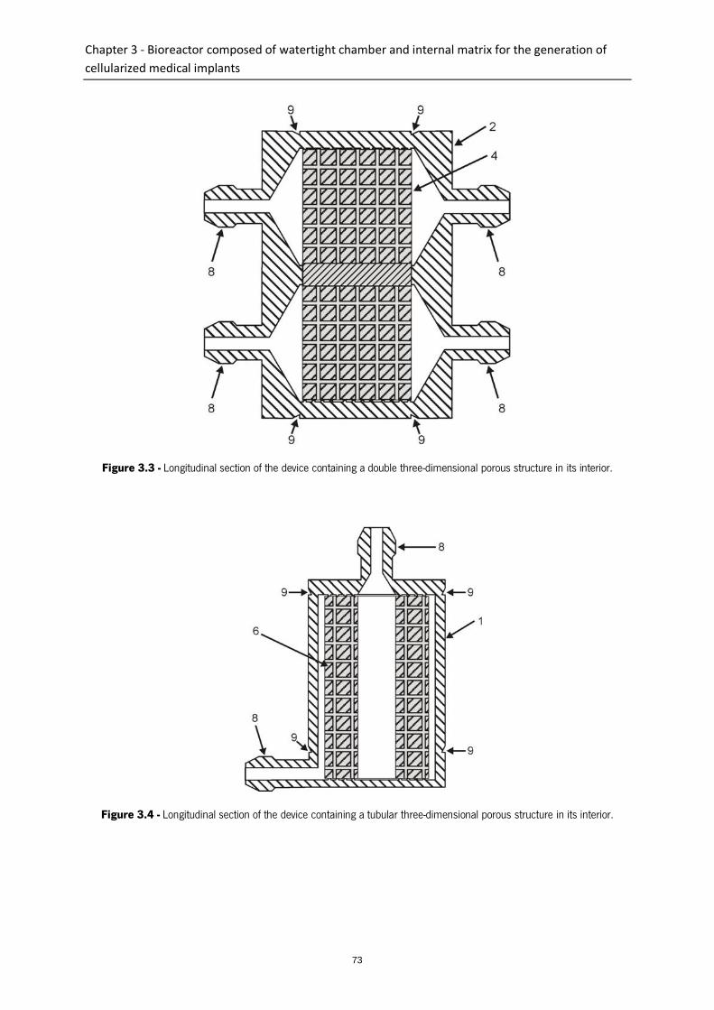
Chapter 3 - Bioreactor composed of watertight chamber and internal matrix for the generation of
cellularized medical implants
73
Figure 3.3 - Longitudinal section of the device containing a double three-dimensional porous structure in its interior.
Figure 3.4 - Longitudinal section of the device containing a tubular three-dimensional porous structure in its interior.
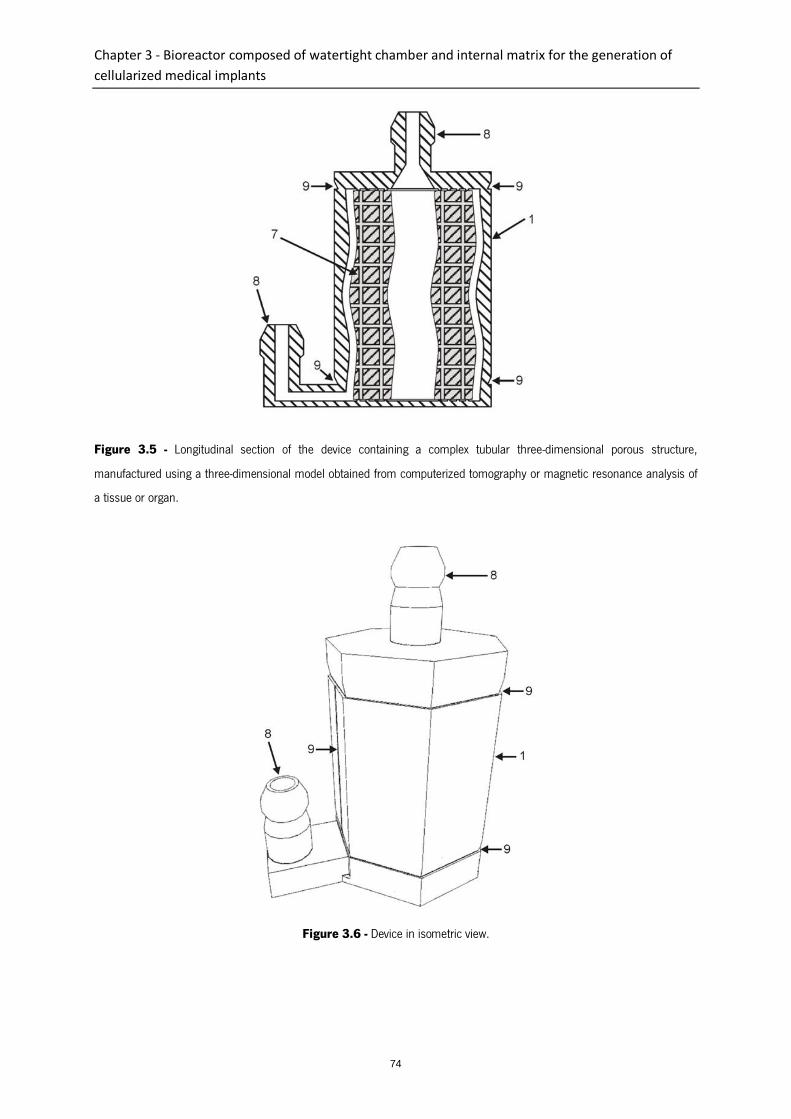
Chapter 3 - Bioreactor composed of watertight chamber and internal matrix for the generation of
cellularized medical implants
74
Figure 3.5 - Longitudinal section of the device containing a complex tubular three-dimensional porous structure,
manufactured using a three-dimensional model obtained from computerized tomography or magnetic resonance analysis of
a tissue or organ.
Figure 3.6 - Device in isometric view.
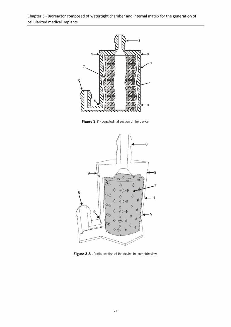
Chapter 3 - Bioreactor composed of watertight chamber and internal matrix for the generation of
cellularized medical implants
75
Figure 3.7 - Longitudinal section of the device.
Figure 3.8 - Partial section of the device in isometric view.
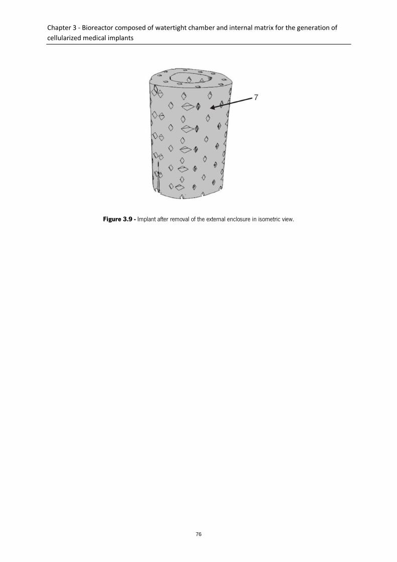
Chapter 3 - Bioreactor composed of watertight chamber and internal matrix for the generation of
cellularized medical implants
76
Figure 3.9 - Implant after removal of the external enclosure in isometric view.
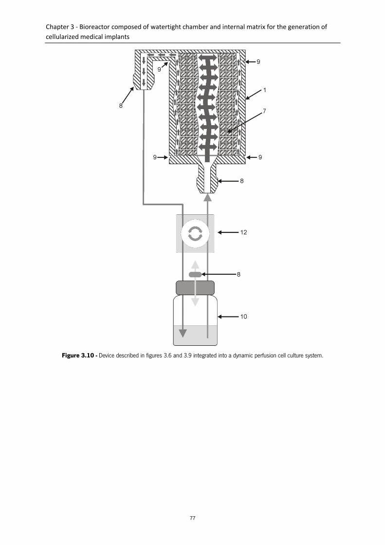
Chapter 3 - Bioreactor composed of watertight chamber and internal matrix for the generation of
cellularized medical implants
77
Figure 3.10 - Device described in figures 3.6 and 3.9 integrated into a dynamic perfusion cell culture system.


Chapter 4 - Biofabrication of customized bone grafts by combination of additive manufacturing and
bioreactor technologies
79
Chapter 4
Biofabrication of customized bone grafts by combination of additive manufacturing and
bioreactor technologies
Abstract
This study reports on an original concept involving additive manufacturing for the fabrication of
customized tissue engineered constructs, offering the possibility of concomitantly manufacturing a
scaffold and a bioreactor chamber to any size and shape. As a proof of concept towards the
development of anatomically relevant tissue engineered constructs, additive manufacturing was utilized
for the design and fabrication of a sheep-tibia scaffold around which a bioreactor chamber of similar
shape was simultaneously constructed. The morphology of the resulting device was investigated by
micro-computed tomography and scanning electron microscopy (SEM) confirming the porous
architecture of the internal scaffold as opposed to the non-porous nature of the bioreactor chamber.
Additionally, this study demonstrates that both the shape, as well as the inner architecture of the device
can significantly impact the perfusion of fluid within the scaffold. Indeed, fluid flow modelling revealed
that this was of significant importance for controlling the nutrition flow pattern within the scaffold and
the device, avoiding the formation of stagnant regions detrimental for in vitro tissue development. The
device was further seeded with human primary osteoblasts and cultured under bidirectional perfusion
for 2 and 6 weeks. Primary human osteoblasts were observed homogenously distributed throughout
the scaffold, and were viable for the 6 weeks culture period. This work demonstrates a novel
application for additive manufacturing in the development of scaffolds and bioreactors. Given the
intrinsic flexibility of this technology, more complex culture systems can be fabricated which would
contribute to the advancement of customized tissue engineering strategies for a wide range of
applications.
This chapter is based on the following publication:
Costa P.F., Vaquette C., Baldwin J., Gomes, M.E., Reis R.L., Theodoropoulos, C., Hutmacher D.W.,
2013, Biofabrication of customized bone grafts by combination of additive manufacturing and
bioreactor technologies, Biofabrication, Submitted.

Chapter 4 - Biofabrication of customized bone grafts by combination of additive manufacturing and
bioreactor technologies
80
1. Introduction
Personalized medical therapy is an emerging practice of medical treatment offering tailored solutions to
each individual. This approach is envisioned to revolutionize healthcare, with cost-effectiveness,
efficiency and improved patient outcomes. Currently, the pharmaceutical industry is investing heavily in
this approach through the development of personalized medicine supported by the advancement in
molecular and genomic technologies [1]. To some extent, the field of tissue engineering is following a
similar path with increasing attention given to the development of customized tissue engineered
products that would meet the patient-specific requirements for replacing organs or tissues.
Additive manufacturing (AM) is one of the many engineering technologies that have been utilized in
tissue engineering, and is central for the fabrication of customized implants. Additive manufacturing
builds objects in a layer-by-layer manner by gradual deposition of materials in an organized fashion,
permitting the fabrication of three-dimensional (3D) objects of highly complex architecture [2].
However, the development of customized constructs of large dimensions and their subsequent cell
culture remained challenging because of the requirements for appropriate oxygen and nutrient diffusion
throughout the entire construct. By utilizing bioreactors, rather than traditional static cultures,
enhanced fluid diffusion within the scaffold can be achieved, permitting in vitro culture under highly
controlled conditions [3]. Bioreactors are usually designed to meet specific requirements for a
standardized scaffold size and shape, type of perfusion, desired fluid flow pattern, type of applied
stimulatory factors (biochemical or biomechanical), and integrated sensorial probes [4-10]. These
points exemplify the degree of complexity achieved in traditional bioreactors, as well as, the lack of
versatility when anatomical scaffolds are considered for tissue engineering applications. Indeed, this
represents a major limitation to the generalized use of bioreactors in personalized tissue engineering
strategies as any modifications of a standardized bioreactor chamber engender considerable additional
engineering steps and therefore result in significantly increased labour and cost.
Control over the fluid flow pattern within the construct is a crucial parameter for the proliferation and
survival of cultured cells in 3D. Shear stress resulting from fluid perfusion is known to influence cell
behaviour and more importantly perfusion is able to positively impact on cell survival by avoiding the
formation of regions where culture media is stagnant [11-17]. This suggests that the architecture of the
bioreactor should be similar to that of the scaffold for achieving homogeneous fluid perfusion and
alleviating the aforementioned issues. A significant advance towards the development of anatomically
shaped bioreactor chambers was performed by Grayson et al [10] who fabricated a scaffold resembling

Chapter 4 - Biofabrication of customized bone grafts by combination of additive manufacturing and
bioreactor technologies
81
a bovine temporomandibular joint (TMJ) condylar bone and cultured the resulting construct in a
bioreactor of similar dimensions. The anatomically shaped bioreactor’s chamber was produced by
casting polydimethylsiloxane (PDMS) around a TMJ-like mould, inserted into a cylindrical tube which
was utilized to hold the scaffold for achieving appropriate fluid transfer to the construct’s most central
portions. This technique required multiple steps and lacked versatility for facilitating the addition of new
bioreactor features such as additional inlets and variation in scaffold dimension. Although promising,
this approach still requires the revision of the bioreactor design when tailoring to suit anatomically
different samples, indicating that even though scaffolds can be easily fabricated into an array of unique
but specific anatomical dimensions, it is not necessarily the case for bioreactor chambers.
Based on this background, we hypothesized that additive manufacturing could be utilized to
simultaneously fabricate both the scaffold and the bioreactor chamber and provide sufficient flexibility
for rapidly manufacturing devices with various anatomical shapes. This concept inherits a high degree
of process automation, hence enabling the fabrication of high quality personalized tissue engineered
constructs in a reproducible manner and at an efficient cost and speed. This study reports on a proof
of concept that additive manufacturing involving a commercial inexpensive dual polymer extrusion
system is capable of fabricating anatomical complex devices, comprising of an ovine tibia scaffold, and
a bioreactor chamber in one single step.
2. Materials and Methods
2.1. Design and fabrication concept
The general design methodology employed in this study begins with the generation of a 3D numerical
model for any tissue or organ by micro-computed tomography (micro-CT) imaging which is then
converted into a three-dimensional replica with pre-determined porosity. An outer shell, referred herein
as bioreactor chamber, possessing inlets/outlets is then designed around the replica in order to
manufacture, in one step, an anatomically shaped device comprising of an anatomically-optimized
scaffold inserted into a customized bioreactor chamber. This allows for the perfusion of the resulting
scaffold during in vitro culture, while better controlling the flow and shear stress in the system. As a
proof of concept, we scanned a 3 cm ovine tibia section by micro-CT to create a numerical 3D model
which was subsequently imported into 3Ds Max (Autodesk, USA) software. The 3D model was vertically
re-oriented and both extremities of the tibial model were trimmed for obtaining horizontal flat surfaces
Chapter 4 - Biofabrication of customized bone grafts by combination of additive manufacturing and
bioreactor technologies
82
and resulted in the final model having a total length of 2.5 cm. The 3D design tool, extrusion, was then
used to generate a shell wall around the lateral and top outer surfaces of the 3D model. The generated
wall was 1 mm thick and 1 mm-spaced from the 3D scaffold model’s outer surfaces. The top part of
the shell was converted to a tubular conical shape possessing a slope angle of 55 o in order to be self-
supportive. This part of the shell was designed to enable an adequate fluid flow on the interior of the
device, and to provide sufficient space for containing extra culture medium. The top end of this conical
medium reservoir had a slope angle of 90o creating an inlet/outlet structure with an inner diameter of
2mm onto which tubing could be connected. The bottom corners of the chamber were additionally
chamfered by 2 mm with a slope angle of 45º to improve the hydrodynamic design. On the bottom
part of the device, a plate containing a 1 mm-wide mini channel was designed, allowing connectivity of
the centre of the plate to a lateral 2 mm diameter inlet/outlet. Furthermore, by using the same
extrusion design tool, a plain column was also generated for filling the empty space located in the
centre of the tibia-shaped model.
2.2. Fluid flow modelling
A computational fluid dynamics approach was used to simulate the flow pattern of the media in various
device architectures. The studied architectures diverged in three main aspects: utilization of
rectangular/chamfered chamber bottom corners, presence/absence of a central filler column for filling
the void space inside the tibia model, and utilization of wide/narrow top inlets/outlets. Given the high
complexity of the device, a simplified model consisting of two-dimensional sections was created in
Design Modeler 13.0 software (Ansys, USA). A profile corresponding to the section of a tubular scaffold
with a length of 2.5 cm, an outer diameter of 13 mm and inner diameter of 6 mm was considered. The
thickness of the simplified section was 0.1mm while the maximum face size of the resulting mesh was
0.2 µm. The fluid flow velocity profiles were calculated using Fluent 13.0 software, within Ansys
Workbench 13.0 platform (Ansys, USA). The pressure at the device’s outlet was assumed to be zero
and the scaffold and bioreactor chamber were considered rigid and impermeable. We assumed that the
viscosity and the density of the culture media at 37°C were η = 1.45·10−3 Pa.s) and (ρ = 1000 kg.m−3)
respectively.

Chapter 4 - Biofabrication of customized bone grafts by combination of additive manufacturing and
bioreactor technologies
83
2.3. Conversion, slicing and prototyping of 3D models
Fluid flow modelling permitted the selection of an optimized device design which was subsequently
utilized in the rest of the study. The device’s 3D model was then sliced and converted to a G-Code file.
The volume corresponding to the 3D tibia to be converted to a porous scaffold was processed using the
open source software Reprap (Online Reprap Community). The 3D tibia model was sliced into 0.27 mm
layers composed of deposition path lines with a spacing of 1.5 mm. On the other hand, the volume
corresponding to the outer shell device was sliced and converted to G-Code files by using the open
source software ReplicatorG (Online ReplicatorG Community). The conversion was performed using 2
shells, a slice thickness of 0.27 mm, an object infill of 100%, a feed rate of 20 mm/s and a travel feed
rate of 55 mm/s as parameters. The G-Code generated through RepRap and ReplicatorG were then
merged together in order to generate one single G-Code file.
The prototyping of the devices was performed using an open source dual extrusion rapid prototyping
machine (Replicator, Makerbot Industries, USA). The materials used were poly(lactic) acid (PLA) Ingeo
4043D (NatureWorks LLC, USA) for the porous scaffolds and acrylonitrile butadiene styrene (ABS)
(Makerbot industries, USA) for the bioreactor chamber. The temperature used for fusing both materials
in their corresponding nozzles was 220ºC. Both materials were deposited through coordinated and
alternating operation of the nozzles.
2.4. Bioreactor surface treatment
In order to ensure that fluid leakage could not occur during subsequent cell culture, a post-treatment
coating of ABS was applied to the outer bioreactor wall surfaces for closing any porosity. In brief, after
capping all inlets/outlets, the devices were immersed for 2 seconds in an ABS/acetone 60 mg/mL
solution and then air-dried at room temperature for 30 min. This procedure was performed twice.
Finally, the devices were washed in distilled water to remove residual solvent.
2.5. Scaffold surface treatment
Given the hydrophobic nature of PLA, which could hinder appropriate and homogeneous fluid perfusion
through the device, alkaline etching was performed using a 2M sodium hydroxide (NaOH) solution. The
devices were rinsed in 100 % ethanol solution under vacuum for one hour to pre-wet the scaffold fibre

Chapter 4 - Biofabrication of customized bone grafts by combination of additive manufacturing and
bioreactor technologies
84
surfaces. After the removal of ethanol, sodium hydroxide solution was perfused through the device until
the bioreactor was entirely filled. The devices were incubated for 30 minutes at room temperature
under vacuum prior to a secondary incubation at 37°C for 60 minutes. Finally, the devices were
washed several times with distilled water and then air-dried. In order to assess the efficacy of the NaOH
treatment, the same protocol was performed onto 8 mm cubic scaffolds having similar architecture but
not inserted in the device. Images of fluid infiltration within the construct prior and after NaOH
treatment were taken using a digital camera.
2.6. Micro computerized tomography analysis (Micro-CT)
The devices were analyzed by micro-CT (µCT40, SCANCO Medical AG, Brüttisellen, Switzerland) at a
resolution of 12 µm, a voltage of 55 kVp, and at a current of 175 µA. Three-dimensional images were
reconstructed from the scans by the micro-CT system software.
2.7. In vitro study
Cell culture took place over 6 weeks and was performed under bidirectional perfusion. A 1 mL sterile
syringe was connected to the device’s medium inlet using sterile silicone tubing. This apparatus was
mounted on a multi-syringe adapter placed on an Aladdin syringe pump (World Precision Instruments,
USA). A total of 6 devices (each with a dedicated syringe) were simultaneously cultured in this system.
The devices were first sterilized by perfusion with 50% ethanol solution for 20 minutes and dried in a
sterile biohazard safety cabinet for 2 hours. The devices were manually filled with 4 mL of basal
medium and bidirectionally perfused overnight at a flow rate of 0.4 mL/min and flow direction inversion
every 100 seconds using the syringe system. This hydration step aimed at promoting the pre-adsorption
of proteins to the scaffold surfaces and hence, facilitating subsequent cell attachment. In order to
ensure the sterility of the device during the culture period while still allowing gas exchange with the
incubator’s environment, a 0.2 µm pore size filter (13 mm diameter) (Pall, USA) was connected to the
outlet positioned at the top of the device.
Primary human osteoblasts were collected from a patient undergoing hip surgery. Ethics approval for
the use of human osteoblasts in this experiment was granted from The Prince Charles Hospital ethics
committee (ethics clearance number: EC2310) and Queensland University of Technology ethics
committee (ethics clearance number 0600000232). The osteoblasts were expanded in basal alpha
Chapter 4 - Biofabrication of customized bone grafts by combination of additive manufacturing and
bioreactor technologies
85
MEM modified medium (Gibco, USA) supplemented with 10% foetal calf serum and 1%
penicillin/streptomycin and used at passage 2. When reaching confluence, the cells were trypsinized
and 1x10⁶ osteoblasts in 250 µl of media were injected into the devices through silicone tubes. The
devices were bi-directionally perfused for 24 hours at a flow rate of 0.4 mL/min in order to allow cell
attachment. The perfusion direction was automatically inverted every 100 seconds utilizing an external
microcontroller connected to the syringe pump.
After 24 hours, the culture medium was replaced by fresh medium and the flow rate was increased to
0.8 mL/min whereas the flow inversion frequency was reduced to 50 seconds. The medium was
changed weekly and the scaffolds were collected for analysis at 2 and 6 weeks post-seeding.
The scaffold collection was performed as follows: the devices were detached from the syringe pump by
removing the silicone tubings and placed in a sterile biohazard safety cabinet. The scaffolds were
retrieved from the interior of the bioreactor chamber by manually sectioning the bioreactor walls using
sterile tweezers and scissors. The collected scaffolds were processed for either 3-(4,5-dimethylthiazol-2-
yl)-2,5-diphenyltetrazolium bromide (MTT) staining, live/dead assay, confocal laser scanning or electron
microscopy.
2.8. Metabolic activity staining
Metabolically active cells were visualized by using a 1 mg/mL 3-(4,5-dimethylthiazol-2-yl)-2,5-
diphenyltetrazolium bromide (MTT) solution. Following retrieval, the scaffolds were washed in PBS and
then immersed into MTT solution for 30 min. Images were captured by a digital camera mounted on an
Eclipse TS100 microscope (Nikon, Tokyo, Japan).
2.9. Live/dead assay (FDA/PI)
Cell viability was assessed using a live/dead assay. The scaffolds were washed twice in PBS, incubated
for 5 minutes at 37ºC in PBS containing 0.67 µg/mL fluorescein diacetate (FDA) and 5 µg/mL
propidium iodide (PI) (both Invitrogen) and washed again in PBS. The cellularised scaffolds were
analysed using a confocal laser scanning microscope (Leica TCS SP5, Leica Microsystems, GmbH). The
excitation/emission wavelengths used for imaging the FDA and PI stainings were respectively 488/518-
568 nm and 561/598-795 nm. A semi-quantitative analysis of the cellular viability was performed using
ImageJ software to quantify living cells (green colour) and dead cells (red colour). A total of seven
Chapter 4 - Biofabrication of customized bone grafts by combination of additive manufacturing and
bioreactor technologies
86
images from multiple regions of interest of the constructs were captured and analysed for each time
point.
2.10. Scanning electron microscopy (SEM)
Osteoblast morphology and distribution in the scaffold was assessed at 2 and 6 weeks post-seeding by
scanning electron microscopy. In brief, samples were fixed in 3% glutaraldehyde, washed in 0.1 M
cacodylate buffer, post-fixed in 1 % osmium tetroxide in cacodylate buffer for 1 hour, prior to
dehydration through sequential graded series of ethanol concentrations. Finally, samples were
immersed in hexamethyldisilazane for 60 min, air dried, mounted onto aluminium stubs and gold
coated. Samples were observed on a FEI Quanta 200 Environmental SEM operating at 10 kV. Scaffolds
without cells were gold coated prior to imaging.
3. Results and discussion
The purpose of this study was to develop and assess an innovative biofabrication-rooted technology for
simultaneously generating anatomically shaped scaffolds and bioreactor chambers for bone tissue
engineering. Additive manufacturing is commonly used for fabricating scaffolds for tissue engineering,
however it is rarely utilized for manufacturing bioreactors. This study is, to our knowledge, the first
report on the utilization of rapid prototyping for designing anatomically shaped bioreactors and scaffolds
in one process. The versatility provided by additive manufacturing technologies enables the production
of highly complex scaffolds which raise a realm of new possibilities, but also new challenges strongly
related to the in vitro culture methods. Indeed, seeding methods are yet to be developed for
homogenously distributing the cells through large constructs such as the ones utilized in the present
study. Also, adequate supply of nutrients and oxygen throughout the entire construct is another
parameter of importance for the generation of viable tissue substitutes. Unlike small and regular-shaped
constructs, the seeding and the culture of anatomically relevant constructs with large dimensions
requires a greater degree of complexity in their design for achieving appropriate in vitro tissue
development. In the context of personalized regenerative strategies, highly versatile manufacturing
platforms are required for their fabrication and the methodology developed in this work intends to
circumvent the abovementioned challenges while still being economically competitive.

Chapter 4 - Biofabrication of customized bone grafts by combination of additive manufacturing and
bioreactor technologies
87
3.1. Fluid flow modelling
The control over the fluid pattern within perfused scaffolds is essential for achieving effective in vitro
culture conditions. Homogenous fluid velocities and absence of stagnant zones are among the main
features defining an optimal culture system. Therefore, multiple architectural configurations were tested
in order to define the most fluid dynamic-efficient design by varying several parameters such as the
utilization of rectangular or chamfered chamber bottom corners, presence or absence of an inner filler
column and wide (same diameter as the scaffold) or narrow top (2 mm diameter) inlet/outlet. Figure
4.1a) depicts the velocity profile of the media perfused in these devices as obtained by numerical
modelling. It was observed that chamfered geometries were the most efficient in avoiding low velocity
sites, in contrast to rectangular geometries where fluid velocities in the vicinity of the rectangular lower
corners dropped to under 2.5% of the inlet fluid velocity. Hidalgo-Bastida et al utilized computational
fluid dynamics for predicting and comparing fluid patterns into rectangular or circular bioreactor
chambers. It was shown that a circular geometry was the most suitable for avoiding both the formation
of stagnant zones in the peripheral regions of the scaffolds and high fluid velocity near the chamber’s
inlets/outlets [18]. However, the regions located between the scaffold and the chamber’s inlets/outlets
were not taken into account despite potential media accumulation in these areas. Figures 4.1a1-4.1a3
clearly show that rectangular bottom corners are prone to the formation of stagnant regions and this is
of particular relevance for vertically oriented perfusion chambers and can induce cell apoptosis caused
by lack of nutrients and oxygen. However, this is eliminated to a large extent by the chamfered
geometry of the bioreactor chamber as demonstrated in figures 4.1a4-4.1a6 where fluid velocities were
always kept 2.5% above initial fluid velocity. The design was further optimized by adding an ABS porous
support structure at the base of the bioreactor (figures 4.1a3-4.1a6), which proved highly efficient at
placing the scaffold away from both stagnant and high fluid velocity regions.
The design of a column internal to the scaffold’s void central part, allowed to efficiently steer the media
towards the central region of the scaffold (figures 4.1a3, 4.1a4 and 4.1a6). This contributed also to
increasing the fluid velocity in the scaffold to 15-20% of the initial value and resulted in establishing a
more homogeneous fluid velocity. This is in contrast to the design without ABS column where the fluid
velocity was much lower (5 to 7.5%) and highly heterogeneous (figures 4.1a5 and 4.1a6). Taking into
consideration that the initial flow rate was 0.8 mL/min, this column design resulted in an homogeneous
flow rate of 0.12-0.16 mL/min in the scaffold, which is similar to what was found in previous studies

Chapter 4 - Biofabrication of customized bone grafts by combination of additive manufacturing and
bioreactor technologies
88
Figure 4.1 – a) Fluid flow modelling of various device inner architectures. a1) Rectangular device with narrow top outlet.
a2) Rectangular device with wide top outlet. a3) Rectangular device with a support structure (located at the bottom) and a
filler column centrally positioned in regard to the scaffold. a4) 2 mm-chamfered chamber with support structure, filler
column and wide outlet. a5) 2 mm-chamfered chamber with support structure, conical outlet but without filler column.
a6) 2 mm-chamfered chamber with support structure, filler column and conical outlet. b) Elements of the device to be
prototyped. b1) Base of the device consisting in a lower plate designed with a mini channel for supplying culture medium
(red) which is covered by another plate containing two holes b2). b3) Medium inlet/outlet and porous structure positioned
over the holes. b4) Filler column centrally positioned in regard to the scaffold. b5) Tailor-made porous scaffold (green)
positioned around the filler column. b6) Bioreactor chamber surrounding the scaffold. c) Fabrication and post-processing
of the device. c1 and c2) Device after rapid-prototyping. c3 and c4) Device after treatment with ABS/acetone solution. d)
Micro-CT reconstruction of device. d1 and d2) Reconstruction depicting the smooth outer ABS-made surface of the device
which was treated with ABS/acetone solution. d3) Cross-section depicting the structure of the device containing an
NaOH-treated PLA scaffold and a central ABS filler column. d4) Morphology of the bioreactor chamber which is
characteristic of a layer-by-layer deposition suggesting that the ABS-acetone post-treatment did not affect the inner wall of
the bioreactor chamber (in contrast to the outer wall shown in d2)).
Chapter 4 - Biofabrication of customized bone grafts by combination of additive manufacturing and
bioreactor technologies
89
where flow rates within this range positively influenced cellular proliferation and development while at
the same time avoiding cell detachment caused by high shear stress [11, 19].
Also, we observed that the utilization of a wide or narrow inlet/outlet configuration at the top of the
device did not significantly affect the flow pattern in the device, however the narrow outlet configuration
(Figure 4.1a6) was selected for the subsequent in vitro culture, as it would effectively reduce the risk of
contamination by permitting the attachment of a sterile air filter.
3.2. Design, fabrication and post-processing of the device
Taking into consideration the results obtained from the fluid flow modelling and considering the specific
needs for the development of a perfusion bioreactor, an optimized device design was achieved by 3D
modelling in the 3Ds Max Software (Figure 4.1b). The bottom part of the device consisted of a base
plate into which a mini channel was integrated (figures 4.1b1 and 4.1b2) for supplying the culture
media in the device. For this purpose, a tubular structure was added at one end of the channel for
connecting the chamber to the culture medium reservoir. As already described in the previous section,
a porous ABS structure was placed at the bottom of the device for allowing homogenous fluid
distribution (Figure 4.1b3). This porous support was 1 mm thick and possessed a cross-section similar
to the one found in the anatomically shaped scaffold. Figure 4.1b4 shows the filler column utilized to
steer the media towards the central portions of the scaffold and reduce the volume of medium
necessary for the cell seeding and subsequent culture. A 1 mm spacing was maintained between the
column and the scaffold for permitting fluid circulation in these locations (Figure 4.1b5). Finally, an
outer bioreactor chamber was designed around the scaffold and its porous support (Figure 4.1b6). This
chamber was positioned at a 1 mm distance from the scaffold and matched the anatomical shape of
the scaffold. While further reducing the volume of media utilized during the in vitro culture, this also
enabled higher control over the fluid flow pattern. Indeed, a bioreactor chamber that follows accurately
the shape of the scaffold ensures effective circulation of the culture medium through the interior of the
construct, not only around its periphery. As seen in the fluid flow simulations, the hydrodynamic design
provided by both the inner column and the bioreactor chamber resulted in homogenous fluid patterns
throughout the interior of the scaffold. Commercially available bioreactor culture systems such as the
U-Cup (Cellec Biotek AG, Switzerland) have shown that bidirectional perfusion enhances cell seeding
efficiency and distribution and results in more reproducible bone formation [5, 20]. In contrast to our
device, the U-Cup is only capable of culturing small cylindrical constructs and hence lacks the versatility
Chapter 4 - Biofabrication of customized bone grafts by combination of additive manufacturing and
bioreactor technologies
90
required for tailor-made applications in which the construct’s shape and architecture need to be
optimized on a case-to-case basis.
The final design (Figure 4.1b6) was saved as an STL file, converted to G-Code using RepRap and
ReplicatorG softwares and finally prototyped in the Makerbot dual extrusion fused deposition prototyping
machine. The time necessary for fabricating each device was 45 minutes. As some open porosity
remained within the bioreactor chamber, a post-treatment with an ABS solution was utilized in order to
close these pores, hence ensuring that no leaking would occur during the subsequent cell culture. As
shown in Figure 4.1d, the treatment reduced the outer surface roughness of the bioreactor chamber
and all interlayer micro-gaps were eliminated. This significantly affected the appearance of the
chamber’s outer wall as shown in Figure 4.1c as the post-treated material appeared smoother and with
a glossy finish. Acetone-based solutions are commonly used as cements for repairing, welding and
smoothing, as well as for waterproofing structures made of ABS [21, 22].
In contrast to this, the NaOH post-treatment on the PLA scaffold resulted in high surface roughness and
consequently higher hydrophilicity when compared to untreated samples (Figure 4.2) which was in
accordance with a previous study [23]. This post-treatment exemplifies the fact that other types of
surface modification can be performed on the scaffold by simply perfusing fluids within the device such
as simulated body fluid for a biomimetic coating [24-26].
The high versatility provided by additive manufacturing combined with the concept we have developed
in this study, permits and facilitates the optimization of numerous devices with different shapes and
sizes where various design features such as additional inlet/outlet can be incorporated. Indeed, unlike
traditional bioreactors, one major advantage of this culture platform is that both culture chamber and
scaffold designs can be freely modified and optimized according to the intended tissue engineering
application without any additional engineering steps or increased costs.
Although in this study a rather simple scaffold architecture [27] was utilized, which mimicked an ovine
tibia, and hence relatively basic in its shape and design, other scaffolds with more complex and
heterogeneous architectures could be fabricated with the method described in this study. This high
versatility in the design and manufacturing of both the scaffold and the culture chamber is the main
characteristic that distinguishes this technology platform from other currently existing devices. For
instance, a comparison with the strategy developed by Grayson et al [10], clearly shows the superior
properties of our concept in regard to the design and the manufacturing. Indeed, the fabrication of the
devices is performed in one single step while permitting the maintenance of a high degree of accuracy
in the architecture and the shape of the scaffold or the bioreactor chamber.

Chapter 4 - Biofabrication of customized bone grafts by combination of additive manufacturing and
bioreactor technologies
91
Figure 4.2 - Effect of NaOH treatment. a and b) Scanning electron micrographs obtained from the surface of untreated,
a) and b) and NaOH-treated scaffold c) and d). e) Scaffold retrieved from the device. f) Increased hydrophilicity resulting
from the NaOH treatment, untreated (left) and NaOH-treated test scaffolds (right) when hydrated with culture medium.
3.3. Perfusion cell culture
The perfusion bioreactor was composed of various devices with their top air inlet/outlets capped with
syringe filters (Figure 4.3a2) and connected to individual syringes mounted into one single syringe
pump by means of a multi-syringe adapter (Figure 4.3a1). After an overnight incubation of the scaffold
in culture media, the cell suspension was injected into the device and the bidirectional perfusion was
applied for achieving a homogeneous seeding. After 2 and 6 weeks of culture, the scaffolds were
collected by manually opening the devices utilizing sterile scissors and tweezers as depicted in Figure
4.3b. The MTT staining revealed the distribution of viable cells at 2 and 6 weeks (Figure 4.4a). Indeed

Chapter 4 - Biofabrication of customized bone grafts by combination of additive manufacturing and
bioreactor technologies
92
cells were well distributed throughout the length of the scaffold, and also on the outer and inner
portions of the architecture confirming that appropriate in vitro culture conditions were achieved. The
MTT staining observations were corroborated by SEM analysis (Figure 4.4b) which showed
homogeneous cell distribution and intimate attachment onto the scaffold. Also it was observed that the
cells were covering the polymer struts of the scaffold, although this was more pronounced at 6 weeks
post-seeding. In some cases cells were capable of spanning the nearby struts as shown in Figure 4.4b.
FDA/PI staining and confocal laser scanning microscopy confirmed the homogeneity of the cell
distribution while assessing their viability (Figure 4.4c) despite the technical challenges encountered
Figure 4.3 – a) Structure of the cell culture apparatus. a1) Schematic representation of the device being bidirectionally
perfused with culture medium using a syringe mounted onto a syringe pump. a2) Device with upper inlet capped with a
syringe filter for preserving sterility and for gas exchange. A silicone tube is connected to the lower inlet/outlet for
bidirectional circulation of culture medium. b) Procedure for retrieving the construct from the culture device by manually
breaking and cutting with the aid of sterile scissors and tweezers.

Chapter 4 - Biofabrication of customized bone grafts by combination of additive manufacturing and
bioreactor technologies
93
when imaging large dimension samples. Therefore, the scaffolds were divided in three zones - top,
middle and bottom region - similarly to what was performed in the rest of this study. This revealed that,
despite the presence of some dead cells (stained in red), the vast majority of the cells were alive
(green). No significant difference in cell viability was observed when semi-quantitatively comparing the
various sites of the construct. Although a slight increase in dead cells at the bottom region was
observed, it did not reach statistical significance. The percentage of living cells at 2 and 6 weeks was
70% ± 10 and 74% ± 18 respectively (Table 4.1). These results demonstrate that nutrients were able to
homogeneously diffuse throughout the entire construct, resulting in an even distribution of viable cells in
the scaffold and validating the fluid flow model predicting a homogenous flow pattern inside the device.
2 Weeks 6 Weeks
Percentage of live cells (%) 70.15 ± 10.14 74.29 ± 18.45
Figure 4.4 – a) MTT staining of human osteoblast-cultured scaffolds at 2 and 6 weeks culture timepoints. b) Scanning
electron micrographs of human osteoblast-cultured scaffolds at 2 and 6 weeks culture timepoints. c) FDA/PI viability
staining of human osteoblast-cultured scaffolds at 2 and 6 weeks culture timepoints showing viable cells in green and
dead cells in red.
Table 4.1 - Statistical analysis of percentage of live cellular content in cultured samples.

Chapter 4 - Biofabrication of customized bone grafts by combination of additive manufacturing and
bioreactor technologies
94
4. Conclusions
In this study, we have developed a unique concept based on additive manufacturing for the integrated
and simultaneous manufacturing of anatomically shaped scaffolds and customized bioreactor
chambers. As a proof of concept, a tailor-made critical size bone tissue substitute was generated by
manufacturing a scaffold mimicking the shape of a sheep tibia section into which osteoblasts were
seeded and cultured. We foresee that this innovative concept will represent a significant advancement
in further implementing the currently available biofabrication toolbox towards the development of
automated customisation of tissue engineered products.
5. Acknowledgements
This work was supported by the NHMRC, the Australian Research Council. Pedro Costa acknowledges
the Portuguese Foundation for Science and Technology for his PhD grant (SFRH/BD/62452/2009).
6. References
[1] Bates S 2010 Progress towards personalized medicine Drug Discov. Today. 15 115-120.
[2] Grylls R 2003 Intricate parts from the inside out Machine Design. 75 56-62.
[3] Martin I, Wendt D and Heberer M 2004 The role of bioreactors in tissue engineering Trends
Biotechnol. 22 80-86.
[4] Bancroft G N, Sikavitsas V I and Mikos A G 2003 Design of a flow perfusion bioreactor system
for bone tissue-engineering applications Tissue Eng. 9 549-554.
[5] Wendt D, Marsano A, Jakob M, Heberer M and Martin I 2003 Oscillating perfusion of cell
suspensions through three-dimensional scaffolds enhances cell seeding efficiency and uniformity
Biotechnol. Bioeng. 84 205-214.
[6] Costa P F, Martins A, Neves N M, Gomes M E and Reis R L 2009 Multichamber bioreactor with
bidirectional perfusion integrated in culture system for tissue engineering strategies: European Patent
Application 09009863.
[7] Orr D E and Burg K J L 2008 Design of a modular bioreactor to incorporate both perfusion flow
and hydrostatic compression for tissue engineering applications Ann. Biomed. Eng. 36 1228-1241.
Chapter 4 - Biofabrication of customized bone grafts by combination of additive manufacturing and
bioreactor technologies
95
[8] Schulz R M, Wuestneck N, van Donkelaar C C, Shelton J C and Bader A 2008 Development
and Validation of a Novel Bioreactor System for Load- and Perfusion-Controlled Tissue Engineering of
Chondrocyte-Constructs Biotechnol. Bioeng. 101 714-728.
[9] Janssen F W, Oostra J, van Oorschot A and van Blitterswijk C A 2006 A perfusion bioreactor
system capable of producing clinically relevant volumes of tissue-engineered bone: In vivo bone
formation showing proof of concept Biomaterials. 27 315-323.
[10] Grayson W L, Frohlich M, Yeager K, Bhumiratana S, Chan M E, Cannizzaro C, Wan L Q, Liu X
S, Guo X E and Vunjak-Novakovic G 2010 Engineering anatomically shaped human bone grafts P. Natl.
Acad. Sci. USA. 107 3299-3304.
[11] Goncalves A, Costa P, Rodrigues M T, Dias I R, Reis R L and Gomes M E 2011 Effect of flow
perfusion conditions in the chondrogenic differentiation of bone marrow stromal cells cultured onto
starch based biodegradable scaffolds Acta Biomater. 7 1644-1652.
[12] Bancroft G N, Sikavitsast V I, van den Dolder J, Sheffield T L, Ambrose C G, Jansen J A and
Mikos A G 2002 Fluid flow increases mineralized matrix deposition in 3D perfusion culture of marrow
stromal osteloblasts in a dose-dependent manner P. Natl. Acad. Sci. USA. 99 12600-12605.
[13] Cartmell S H, Porter B D, Garcia A J and Guldberg R E 2003 Effects of medium perfusion rate
on cell-seeded three-dimensional bone constructs in vitro Tissue Eng. 9 1197-1203.
[14] Goldstein A S, Juarez T M, Helmke C D, Gustin M C and Mikos A G 2001 Effect of convection
on osteoblastic cell growth and function in biodegradable polymer foam scaffolds Biomaterials. 22
1279-1288.
[15] Grayson W L, Bhumiratana S, Cannizzaro C, Chao P H G, Lennon D P, Caplan A I and Vunjak-
Novakovic G 2008 Effects of Initial Seeding Density and Fluid Perfusion Rate on Formation of Tissue-
Engineered Bone Tissue Eng. Pt. A. 14 1809-1820.
[16] Meinel L, Karageorgiou V, Fajardo R, Snyder B, Shinde-Patil V, Zichner L, Kaplan D, Langer R
and Vunjak-Novakovic G 2004 Bone tissue engineering using human mesenchymal stem cells: Effects
of scaffold material and medium flow Ann. Biomed. Eng. 32 112-122.
[17] Sikavitsas V I, Bancroft G N, Holtorf H L, Jansen J A and Mikos A G 2003 Mineralized matrix
deposition by marrow stromal osteoblasts in 3D perfusion culture increases with increasing fluid shear
forces P. Natl. Acad. Sci. USA. 100 14683-14688.
[18] Hidalgo-Bastida L A, Thirunavukkarasu S, Griffiths S, Cartmell S H and Naire S 2012 Modeling
and design of optimal flow perfusion bioreactors for tissue engineering applications Biotechnol. Bioeng.
109 1095-1099.
Chapter 4 - Biofabrication of customized bone grafts by combination of additive manufacturing and
bioreactor technologies
96
[19] Alvarez-Barreto J F, Linehan S M, Shambaugh R L and Sikavitsas V I 2007 Flow perfusion
improves seeding of tissue engineering scaffolds with different architectures Ann. Biomed. Eng. 35
429-442.
[20] Scherberich A, Galli R, Jaquiery C, Farhadi J and Martin I 2007 Three-dimensional perfusion
culture of human adipose tissue-derived endothelial and osteoblastic progenitors generates osteogenic
constructs with intrinsic vascularization capacity Stem Cells. 25 1823-1829.
[21] Galantucci L M, Lavecchia F and Percoco G 2009 Experimental study aiming to enhance the
surface finish of fused deposition modeled parts Cirp. Ann-Manuf. Techn. 58 189-192.
[22] Galantucci L M, Lavecchia F and Percoco G 2010 Quantitative analysis of a chemical treatment
to reduce roughness of parts fabricated using fused deposition modeling Cirp. Ann-Manuf. Techn. 59
247-250.
[23] Yang J, Wan Y Q, Tu C F, Cai Q, Bei J Z and Wang S G 2003 Enhancing the cell affinity of
macroporous poly(L-lactide) cell scaffold by a convenient surface modification method Polym. Int. 52
1892-1899.
[24] Kokubo T, Kushitani H, Sakka S, Kitsugi T and Yamamuro T 1990 Solutions Able to Reproduce
Invivo Surface-Structure Changes in Bioactive Glass-Ceramic a-W3 J. Biomed. Mater. Res. 24 721-734.
[25] Kokubo T, Ito S, Huang Z T, Hayashi T, Sakka S, Kitsugi T and Yamamuro T 1990 Ca, P-rich
layer formed on high-strength bioactive glass-ceramic A-W J. Biomed. Mater. Res. 24 331-343.
[26] Vaquette C, Ivanovski S, Hamlet S M and Hutmacher D W 2013 Effect of culture conditions and
calcium phosphate coating on ectopic bone formation Biomaterials. 34 5538-5551.
[27] Reichert J C, Wullschleger M E, Cipitria A, Lienau J, Cheng T K, Schutz M A, Duda G N, Noth U,
Eulert J and Hutmacher D W 2011 Custom-made composite scaffolds for segmental defect repair in
long bones Int. Orthop. 35 1229-1236.

Chapter 5 - Additive manufacturing for high throughput screening of 3D tissue engineered constructs
in dynamic culture
97
Chapter 5
Additive manufacturing for high throughput screening of 3D tissue engineered constructs
in dynamic culture
Abstract
The utilisation of high throughput screening (HTS), in a pharmaceutical, toxicity on top of a tissue
engineering and regenerative medicine context, relies on the ability to test large arrays of cell and
biomaterial combinations in 3D environments. Here, we report on the development of a highly versatile
and up-scalable method based on additive manufacturing for the fabrication of arrays of scaffolds
enclosed in individualised perfusion chambers. This technique allowed the simultaneous in vitro culture
of 96 scaffolds under controlled bi-directional perfusion. The methodology developed in this work
exemplifies the applicability of additive manufacturing as a tool for achieving further automation of HTS
in the field of biomedical science and biotechnology.
This chapter is based on the following publication:
Costa P.F., Hutmacher D.W., Theodoropoulos C., Gomes M.E., Reis R.L., Vaquette C., 2013, Additive
manufacturing for high throughput screening of 3D tissue engineered constructs in dynamic culture,
Nature Materials, Submitted.

Chapter 5 - Additive manufacturing for high throughput screening of 3D tissue engineered constructs
in dynamic culture
98
1. Introduction
Tissue engineering is based on the combination of cells and three-dimensional (3D) porous scaffolds to
facilitate the replacement and regeneration of damaged tissues.[1] As such, scaffolds should enable
both the maintenance of sufficient oxygen diffusion and nutrient supply in vitro, and provide mechanical
support and space maintenance to allow the formation of new tissue and appropriate vascularisation in
vivo. Further, these scaffolds with a tailored composition/architecture when combined with cells of
interest and any necessary biochemical and physical cues, are essential for the successful development
of tissue-engineered constructs (TEC) with desirable in vivo properties[2, 3]. This is generally achieved
through an extensive and time consuming optimisation process.
High throughput screening (HTS) enables a large number of optimisation tests under automated and
highly controlled conditions to be conducted simultaneously. This methodology is widely utilised for
screening compounds for drug discovery purposes [4] and has been also proposed for screening three-
dimensional structures for tissue engineering applications.[5-11] However in the majority of existing
HTS devices, several drawbacks remain when screening biomaterials and more specifically 3D
scaffolds. One of the main limitations is the mostly two-dimensional nature of the protocols utilised for
investigating cellular response and behaviour, which may not necessarily be relevant in 3D
environments.[12-15] Fluid diffusion and associated nutrient and oxygen supply within a given construct
along with cell-material and cell-cell interactions are also crucial parameters, which greatly influence in
vitro cellular maturation. These aspects are particularly critical when considering the use of large
dimension constructs close to that required in the target application and when the cell culture is
performed statically, as is the case in the vast majority of HTS devices. Flow perfusion bioreactors are
traditionally utilised to circumvent these aforementioned issues in scaffolds with significantly larger
dimensions. Perfusion improves nutrient supply and distribution and therefore avoids cell death in the
most central regions of the scaffolds.[16-28] However, the lack of versatility in current perfusion
bioreactor systems does not permit user-friendly design modifications such as incorporating additional
culturing chambers and the flexibility in a short period of time to utilise scaffolds of various sizes. In
some flow perfusion bioreactors, sub-optimal fluid flow distribution allows media to flow around the
scaffold but does not necessarily perfuse though the construct when the scaffold dimension is
significantly different to that of the bioreactor chamber.[25] These design limitations greatly impede the
fabrication and testing of large arrays of scaffolds with multiple characteristics (such as architecture,
dimensions, shape etc.) in a high throughput manner.

Chapter 5 - Additive manufacturing for high throughput screening of 3D tissue engineered constructs
in dynamic culture
99
Additive manufacturing technologies such as fused deposition modelling, offer the possibility to rapidly
generate arrays of porous 3D constructs with different shapes and architectures in a highly controlled
and reproducible manner.[29-33] In a previous report,[34] we utilised this technology for fabricating an
anatomically relevant device comprising a porous scaffold replica of an ovine tibia around which a
bioreactor chamber of similar shape was simultaneously built. We hypothesised that this concept could
be further utilised in HTS while circumventing the aforementioned issues associated with the use of
HTS and traditional bioreactors.
As a proof of concept, a device was designed to simultaneously accommodate 8 cubical scaffolds 8
mm in width. These scaffolds were made of polylactic acid (PLA) and composed of 400 µm diameter
struts spaced 1.5 mm horizontally in a 0-90 degree orientation. Fluid flow modelling was used to
optimise the design of the individual culture chambers in the HTS device. The main requirements
considered during this optimisation were: 1) homogeneous fluid velocities throughout the entire scaffold
and 2) the elimination of any stagnant fluid regions. Homogeneous fluid distribution ensures a constant
and uniform supply of nutrients and oxygen within the construct. When similar culture conditions are
achieved throughout the scaffolds, high reproducibility can be achieved. To this end, a number of
different configurations of the culture chamber and geometry of the top outlet (Figure 5.1) were tested.
The geometry of the top outlet was shown to significantly impact on the flow pattern as demonstrated in
Figure 5.1- Fluid flow modelling of various device inner architectures. a) Rectangular device with narrow top outlet. b)
Rectangular device with wide top outlet. c) 2mm-chamfered chamber with support structure and wide top outlet. White
arrows indicate stagnant zones and black arrows indicate high velocity zones.
Chapter 5 - Additive manufacturing for high throughput screening of 3D tissue engineered constructs
in dynamic culture
100
Figure 5.1a and b. Indeed an open outlet (Figure 5.1b) was found to significantly reduce the formation
of both low and high velocity zones in the upper portion of the scaffold when compared to a closed
outlet configuration (Figure 5.1a). Taking into consideration results obtained in a previous study,[35] the
design of the chamber was modified to prevent the formation of regions with heterogeneous fluid
velocity located at the base of the scaffold. To this end, a porous acrylonitrile butadiene styrene (ABS)
structure supporting the PLA scaffold was inserted at the bottom of the chamber. This resulted in
positioning the scaffold away from the high velocity regions (represented in yellow and red and
highlighted by the black arrows in Figure 5.1) located in the vicinity of the inlet/outlet. The chambers
were chamfered 2 mm with an angle of 45º (Figure 5.1c) to eliminate low fluid velocity regions (white
arrows in Figure 5.1a-b) as our demonstrated in our previous work.[34].
This configuration combining the ABS support structure and the chamfered chambers maintained a
homogeneous fluid flow velocity throughout the scaffold ranging from 10% to 15% of the initial flow rate
(Figure 5.1c). At the inlet of each individual chamber, the flow rate was 0.1 mL/min and therefore the
flow rate in the scaffold ranged from 0.01-0.015 mL/min (Figure 5.1c), which is in agreement with
optimal flow rates reported in other studies.[16, 36]
This optimised design of an individual bioreactor chamber was then utilised to fabricate the HTS device.
3Ds Max software was used to design a multi-chamber device which could simultaneously
accommodate 8 scaffolds (Figure 5.2a). Figure 5.2a shows the different elements utilised to create the
numerical 3D model. The base of the device integrated a network of 1 mm wide fluidic channels
connecting each of the eight culture chambers to one single medium inlet/outlet (Figure 5.2a1-5.2a2).
Based on the fluid flow modelling analysis, the bottom of each chamber was chamfered by 2 mm along
an angle of 45° (Figure 5.2a2) onto which a 1 mm thick porous ABS structure (Figure 5.2a3) was
added to support the PLA scaffold represented in green in Figure 5.2a4. Each scaffold was surrounded
by a 10 mm wide square chamber with 1mm thick walls and positioned at a distance of 1mm from the
sides of the scaffolds (Figure 5.2a5). This chamber was 18 mm high to create a reservoir for the
subsequent cell culture as shown in Figure 5.2a6. Two pyramidal structures were then placed over
each group of 4 chambers to fully enclose the device. The final model of the device (Figure 5.2a7) was
saved as an STL file, converted to G-Code using RepRap and ReplicatorG software and finally prototyped
in a Makerbot dual extrusion fused deposition prototyping machine (Figure 5.2b1 and 5.2b2)
(Supplementary Video 1). The time necessary for fabricating each device was 40 minutes.
As some open porosity remained within the bioreactor chamber, surface treatment with an ABS solution
was used in order to close these pores ensuring that no leaking would occur during the subsequent cell

Chapter 5 - Additive manufacturing for high throughput screening of 3D tissue engineered constructs
in dynamic culture
101
culture. As a result of this treatment, the outer surfaces of the device became smoother and glossier
(Figure 5.2b5 and 5.2b6) than non-treated surfaces (Figure 5.2b3 and 5.2b4) due to the elimination of
the roughness and the interlayer gaps. A more detailed analysis was performed using micro-CT which
confirmed that most of the porosity initially contained in the bioreactor walls was either fully closed or
removed by the ABS treatment (Supplementary Figure 5.1a1). This analysis also demonstrated that the
inner walls and the scaffolds were not affected by the ABS/acetone treatment (Supplementary Figure
5.1a2-5.1a4) as shown by the presence of the original interlayer gaps.
Figure 5.2- a) Elements of the device to be prototyped. a1) Base of the device consisting of a lower plate designed with a
mini channel network for supplying culture medium (red) to the eight culture chambers. a2) The channel network is
covered by a perforated layer which defines the chamfered bottom of the culture chambers as well as a lateral
inlet/outlet. a3) Porous support structures positioned over the chamber bottoms. a4) Scaffolds positioned over the
porous support structures on the bottom of each culture chamber. a5) Walls designed around and in between the
scaffolds. a6) Walls extended upwards in order to create an upper reservoir over the scaffolds. a7) Two covers designed
on the top part of the device to enclose the culture chambers. The top of each cover possesses an inlet/outlet for air
circulation. b) Fabrication and post-treatment of device. b1) Dual extrusion prototyping machine. b2) Close-up view of
device being fabricated in the prototyping machine by dual extrusion of ABS (left extruder) and PLA (right extruder). b3-b4)
Device after rapid-prototyping. b5-b6) Device after post-treatment with ABS/acetone solution.

Chapter 5 - Additive manufacturing for high throughput screening of 3D tissue engineered constructs
in dynamic culture
102
The ability to fabricate high throughput culture devices directly from numerically designed 3D models by
additive manufacturing offers significant advantages: it reduces costs and human intervention in the
fabrication process, while permitting a high degree of control over the size and the architecture of the
scaffolds. Generally, the fabrication of high throughput culture devices involves the utilisation of highly
specific technologies and equipment such as clean room facilities, spin coaters, mask aligners or micro-
moulding and laser ablation machines [37, 38] which are not necessarily commonly available in a
research laboratory and moreover, not as economically viable as additive manufacturing. Furthermore,
inherent limitations of these fabrication technologies, such as the need to fabricate one or multiple
master moulds, result in a time consuming, expensive and largely manual manufacturing process.
HTS devices manufactured in such a way have indeed been employed [20, 37] in order to culture
simple-shaped cylindrical scaffolds albeit of smaller dimensions than those developed in the present
study. Unlike conventional HTS where insights are mainly provided at a cellular and hence microscopic
level, the HTS device developed in this study shows the ability to provide further knowledge at a more
macroscopic / tissue level, hence enabling more clinically realistic in vitro assessment. Further, a broad
range of materials can be utilised for fabricating scaffolds and therefore contribute to the development
of a scaffold materials library. The polymer melt-based deposition process permits the fabrication of
objects from a wide array of materials such as aliphatic polyesters, polyurethane, etc.
To further demonstrate the versatility of our strategy, the PLA scaffolds were coated with a calcium
phosphate layer by successively filling the individual culture chambers with NaOH and simulated body
fluid (SBF). Treatment with NaOH increases the hydrophilicity of the scaffold by increasing roughness
(as shown by the micro-porosity in Supplementary Figure 5.1b1-5.1b2) and is also known to increase
the density of carboxylic acid on the surface of the polymeric struts, which has a significant impact on
cell adhesion.[39, 40] The SBF treatment resulted in the deposition of biomimetic calcium phosphate
crystals. However this deposition was not entirely homogenous as agglomerations of CaP spherical
particles were found in many locations of the scaffold as shown in Supplementary Figure 5.1b3-5.1b4,
unlike what was reported in another study utilising a perfusion system for coating scaffolds of similar
architecture.[41] The heterogeneity in the CaP coating probably comes from the relatively short
exposition time and the reduced volume of SBF solution utilised, which did not enable the formation of
a continuous CaP layer. The NaOH post-treatment was performed to obtain a single phase of CaP as a
previous study, although performed on a different scaffold, demonstrated that a highly soluble CaP
phase (brushite) was removed by the gentle etching, leaving a unique carbonate hydroxylapatite
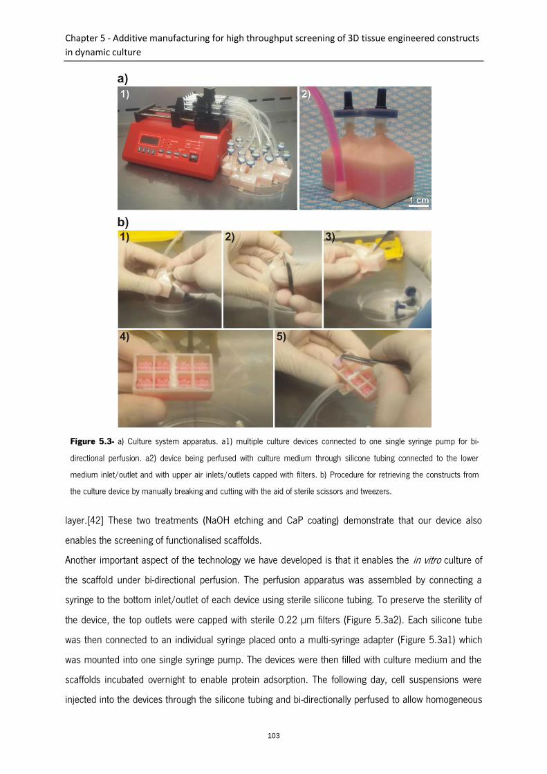
Chapter 5 - Additive manufacturing for high throughput screening of 3D tissue engineered constructs
in dynamic culture
103
layer.[42] These two treatments (NaOH etching and CaP coating) demonstrate that our device also
enables the screening of functionalised scaffolds.
Another important aspect of the technology we have developed is that it enables the in vitro culture of
the scaffold under bi-directional perfusion. The perfusion apparatus was assembled by connecting a
syringe to the bottom inlet/outlet of each device using sterile silicone tubing. To preserve the sterility of
the device, the top outlets were capped with sterile 0.22 µm filters (Figure 5.3a2). Each silicone tube
was then connected to an individual syringe placed onto a multi-syringe adapter (Figure 5.3a1) which
was mounted into one single syringe pump. The devices were then filled with culture medium and the
scaffolds incubated overnight to enable protein adsorption. The following day, cell suspensions were
injected into the devices through the silicone tubing and bi-directionally perfused to allow homogeneous
Figure 5.3- a) Culture system apparatus. a1) multiple culture devices connected to one single syringe pump for bi-
directional perfusion. a2) device being perfused with culture medium through silicone tubing connected to the lower
medium inlet/outlet and with upper air inlets/outlets capped with filters. b) Procedure for retrieving the constructs from
the culture device by manually breaking and cutting with the aid of sterile scissors and tweezers.
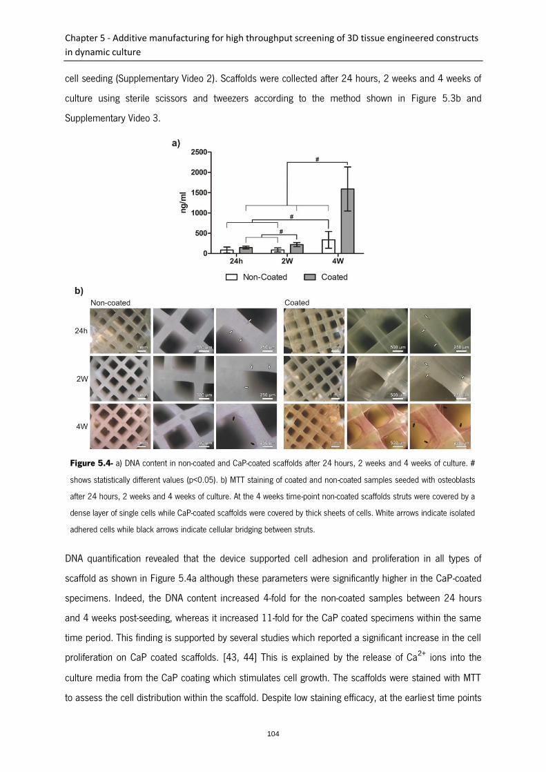
Chapter 5 - Additive manufacturing for high throughput screening of 3D tissue engineered constructs
in dynamic culture
104
cell seeding (Supplementary Video 2). Scaffolds were collected after 24 hours, 2 weeks and 4 weeks of
culture using sterile scissors and tweezers according to the method shown in Figure 5.3b and
Supplementary Video 3.
DNA quantification revealed that the device supported cell adhesion and proliferation in all types of
scaffold as shown in Figure 5.4a although these parameters were significantly higher in the CaP-coated
specimens. Indeed, the DNA content increased 4-fold for the non-coated samples between 24 hours
and 4 weeks post-seeding, whereas it increased 11-fold for the CaP coated specimens within the same
time period. This finding is supported by several studies which reported a significant increase in the cell
proliferation on CaP coated scaffolds. [43, 44] This is explained by the release of Ca2+ ions into the
culture media from the CaP coating which stimulates cell growth. The scaffolds were stained with MTT
to assess the cell distribution within the scaffold. Despite low staining efficacy, at the earliest time points
Figure 5.4- a) DNA content in non-coated and CaP-coated scaffolds after 24 hours, 2 weeks and 4 weeks of culture. #
shows statistically different values (p<0.05). b) MTT staining of coated and non-coated samples seeded with osteoblasts
after 24 hours, 2 weeks and 4 weeks of culture. At the 4 weeks time-point non-coated scaffolds struts were covered by a
dense layer of single cells while CaP-coated scaffolds were covered by thick sheets of cells. White arrows indicate isolated
adhered cells while black arrows indicate cellular bridging between struts.

Chapter 5 - Additive manufacturing for high throughput screening of 3D tissue engineered constructs
in dynamic culture
105
metabolically active cells had homogeneously infiltrated the scaffolds regardless of the surface
treatment (coated and non-coated) as shown in Figure 5.4b. This shows that the chamber design was
effective in homogeneously distributing the cells (highlighted by white arrows) throughout the scaffold
and hence validates the fluid flow simulation analysis.
After 4 weeks of culture, the struts of non-coated scaffolds were covered by a dense layer of single cells
while CaP-coated scaffolds were covered by thick sheets of cells (in red) bridging multiple struts
(highlighted by black arrows in Figure 5.4b). SEM microscopy confirmed the homogeneous cell
distribution in both types of scaffolds and also showed that the cells gradually covered the polymeric
struts and were capable of bridging adjacent struts and partially filling the pores of the scaffold at 4
weeks post-seeding as shown in Figure 5.5.
The distribution and viability of cells in several locations of the scaffolds was also assessed by FDA/PI-
staining and confocal laser microscopy (Figure 5.5). Despite the presence of some dead cells (red) the
great majority of cells were alive (green) at the 4 weeks culture period showing that sufficient nutrient
supply was provided throughout the entire scaffold. This was further shown in the semi-quantitative
analysis in which both coated and non-coated samples displayed a percentage of live cells above 85% at
the 4 weeks culture period (Table 5.1).
Table 5.1- Statistical analysis of percentage of live cellular content in CaP-coated and non-coated constructs after 24
hours, 2 weeks and 4 weeks of culture.
Culture period Non-coated Coated
24 hours 97.53 ± 4.28 93.64 ± 9.88
2 weeks 95.44 ± 6.34 96.80 ± 2.00
4 weeks 85.67 ± 8.22 94.73 ± 3.69
The present study demonstrates that additive manufacturing can be applied to the fabrication of
complex cell culture devices for screening large three-dimensional tissue engineered constructs in a
high throughput manner under highly controlled conditions. As design and testing is performed at the
numerical level and then carried out by the same single automated equipment, the integration of
additive manufacturing in high throughput screening demonstrates the advantage of generating arrays
of three-dimensional scaffolds in a highly reproducible manner while also facilitating possible design
modifications (scaffold number, dimension and architecture). The highly three-dimensional nature of the
device represents a significant advancement in the field as most HTS systems tend to have reduced
three-dimensionality and/or in vitro cell culture is performed under static conditions.[45-47] Also the

Chapter 5 - Additive manufacturing for high throughput screening of 3D tissue engineered constructs
in dynamic culture
106
Figure 5.5- SEM and confocal microscopy (right column) micrographs of non-coated and CaP-coated scaffolds seeded
with osteoblasts after 24 hours, 2 weeks and 4 weeks of culture. Samples observed through confocal microscopy were
stained with FDA/PI showing live cells in green and dead cells in red.

Chapter 5 - Additive manufacturing for high throughput screening of 3D tissue engineered constructs
in dynamic culture
107
automation of the scaffold fabrication along with the bidirectional perfusion enables the systematic
assessment of the performance in a more standardised and highly controlled manner and at an
effective cost and speed. It also reduces variations inherent to manual cell culture, such as differences
in manual cell seeding efficacy, potential contamination due to frequent media change, as well as
variability in volume of media utilised which can affect oxygen diffusion and therefore result in
disparities within samples. Moreover, most bioreactors can test only a few samples at any one time and
therefore systematic assessments involving large number of specimens are highly time consuming and
labour-intensive.[48, 49] This is in contrast to the technology proposed in the present study which is
unprecedented in the literature as it was capable of testing a large number of large 3D samples under
bidirectional perfusion. Indeed, even in a simplified 4 by 2 configuration, 96 three-dimensional scaffolds
contained in 12 separated culture devices were simultaneously cultured demonstrating the high
throughput ability. This utilisation of additive manufacturing provides a new tool for allowing a higher
level of automation of HTS in tissue engineering under three-dimensional and highly controlled dynamic
environments.
2. Experimental
2.1. Design and fabrication concept
Devices targeting HTS applications are required to contain multiple samples for simultaneous testing
and handling. This is usually achieved by using versatile test platforms and by process automation. The
device utilised in this study was designed to be modular and to allow for up-scaling according to the
number of scaffolds required. As a proof of concept, a device was designed to simultaneously
accommodate 8 cubical scaffolds (8 mm width) composed of 400 µm diameter struts 1.5 mm
horizontally spaced in a 0-90 degree orientation. Device design was performed in 3Ds Max (Autodesk,
USA) software and consisted of building individualised bioreactor chambers by placing 1 mm thick walls
around each of the 8 scaffolds, which were organised in a rectangular 2 by 4 configuration. The walls
were positioned 1 mm from the scaffolds and were 10 mm taller than the scaffolds in order to create a
reservoir for the culture medium. The top of every 4 chambers (in a square configuration) was covered
by a pyramidal structure ending in a 2 mm diameter outlet used for attaching sterile filters during
subsequent cell culture. A symmetrical mini-fluidic channel network connected to a 2mm diameter
inlet/outlet was designed for homogenously distributing the culture medium through the various
individual chambers.
Chapter 5 - Additive manufacturing for high throughput screening of 3D tissue engineered constructs
in dynamic culture
108
2.2. Fluid flow modelling
Computational fluid dynamics was used to simulate the flow pattern of the media in various device
architectures. The studied architectures differed in two main aspects: the use of either rectangular or
chamfered chamber bottom corners and the use of either wide or narrow top inlets/outlets. Given the
high complexity of the device, a simplified model consisting of two-dimensional sections was first
created in Design Modeler 13.0 software (Ansys, USA). The profile corresponding to the section of an 8
mm wide cubic porous scaffold surrounded by a 10 mm wide bioreactor chamber was considered. The
thickness of the simplified section was 0.1 mm and the maximum face size of the generated model
mesh was 0.2 µm. The fluid flow velocity profiles were calculated using Fluent 13.0 software within
Ansys Workbench 13.0 platform (Ansys, USA). The pressure at the device’s outlets was assumed to be
zero and the scaffold and the bioreactor chamber were considered rigid and impermeable. We assumed
that the viscosity and the density of the culture media at 37°C were η = 1.45.10−3 Pa.s) and (ρ = 1000
kg.m-3) respectively.
2.3. Conversion, slicing and prototyping of 3D models
The device design displaying the most homogenous fluid flow pattern was selected for further
experiments. The device’s 3D model was then sliced and converted to a G-Code file. The volumes
corresponding to the 8 cubes to be converted to porous scaffolds were processed using the open
source software Reprap (Online Reprap Community). The cubes were sliced into 0.27 mm layers
composed of deposition path lines with a spacing of 1.5 mm. On the other hand, the volume
corresponding to the outer shell device was sliced and converted to G-Code files by using the open
source software ReplicatorG (Online ReplicatorG Community). The conversion was performed using 2
shells, a slice thickness of 0.27 mm, an object infill of 100%, a feed rate of 20 mm/s and a travel feed
rate of 55 mm/s as parameters. The G-Codes generated through RepRap and ReplicatorG were then
merged together in order to generate one single G-Code file. The prototyping of the devices was
performed using an open source dual extrusion rapid prototyping machine (Replicator, Makerbot
Industries, USA). The materials used were poly(lactic) acid (PLA) Ingeo 4043D (NatureWorks LLC, USA)
for the porous scaffolds and acrylonitrile butadiene styrene (ABS) (Makerbot industries, USA) for the
bioreactor chamber. The temperature used for fusing both materials in their corresponding nozzles was
220ºC. Both materials were deposited through coordinated and alternated operation of the nozzles.

Chapter 5 - Additive manufacturing for high throughput screening of 3D tissue engineered constructs
in dynamic culture
109
2.4. Bioreactor surface treatment
In order to ensure that fluid leakage could not occur during subsequent cell culture, a post-treatment
coating of ABS was applied to the outer bioreactor wall surfaces to close any remaining porosity. In
brief, after capping all inlets/outlets, the devices were immersed for 2 seconds in an ABS/acetone 60
mg/mL solution and then air-dried at room temperature for 30 min. This procedure was performed
twice. Finally, the devices were washed in distilled water to remove residual solvent.
2.5. Scaffold surface treatment
Given the hydrophobic nature of PLA which could hinder appropriate and homogeneous fluid perfusion
through the device, alkaline etching was performed using a 2M sodium hydroxide (NaOH) solution. The
devices were rinsed in 100 % ethanol under vacuum for one hour to pre-wet the scaffold fibre surfaces.
After the removal of ethanol, sodium hydroxide solution was perfused through the device until the
bioreactor was entirely filled. The devices were incubated for 30 minutes at room temperature under
vacuum prior to a secondary incubation at 37°C for 60 minutes. Finally, the devices were washed
several times with distilled water and then air-dried prior to proceeding to the deposition of a calcium
phosphate biomimetic coating on the PLA filaments.
2.6. Biomimetic coating of scaffolds
The deposition of the calcium phosphate coating was performed by filling the chambers with a total of 8
mL of 10x Simulated Body Fluid (SBF) solution at pH 6 (solution preparation described elsewhere [42,
50]) for 30 min at 37ºC and followed by perfusion with a 0.5 M sodium hydroxide solution for 30 min
at 37ºC. Finally the coated scaffolds were rinsed five times with ultrapure water and air-dried.
2.7. Micro computerised tomography analysis (Micro-CT)
The devices were analysed by Micro-CT (µCT40, SCANCO Medical AG, Brüttisellen, Switzerland) at a
resolution of 12 µm, a voltage of 55 kVp and at a current of 175 µA. Three-dimensional images were
reconstructed from the scans by the micro-CT system software.

Chapter 5 - Additive manufacturing for high throughput screening of 3D tissue engineered constructs
in dynamic culture
110
2.8. In vitro study
The cell-seeded scaffolds were cultured up to 4 weeks under bi-directional perfusion. To this end, a 1
mL sterile syringe was connected to each device’s medium inlet using sterile silicone tubing. This
apparatus was mounted on a multi-syringe adapter placed on an Aladdin syringe pump (World Precision
Instruments, USA). A total of 12 devices (each with a dedicated syringe) were simultaneously cultured
in this system and therefore 96 scaffolds were cultured at one time. The devices were first sterilised by
perfusion with 50% ethanol solution for 20 minutes and dried in a sterile hood for 2 hours. Each device
was then manually filled with a total of 8 mL of basal medium and bi-directionally perfused overnight at
a flow rate of 0.4 mL/min with flow inversion occurring every 100 seconds. This hydration step aimed
to promote the pre-adsorption of proteins onto the scaffold and hence facilitate subsequent cell
attachment. In order to ensure the sterility of the device during the culture period while still allowing gas
exchange with the incubator’s environment, 0.2 µm pore size filters (13 mm diameter) (Pall, USA) were
connected to the outlets positioned at the top of the devices.
Primary human osteoblasts were collected from a patient undergoing hip surgery. Ethics approval for
the use of human osteoblasts in this experiment was granted from The Prince Charles Hospital ethics
committee (ethics clearance number: EC2310) and Queensland University of Technology ethics
committee (ethics clearance number 0600000232). The osteoblasts were expanded in basal alpha
MEM modified medium (Gibco, USA) supplemented with 10% fetal calf serum and 1%
penicillin/streptomycin and used at passage 2. When reaching confluence, the cells were trypsinised
and 250 µL cell suspensions containing 1x10⁶ osteoblasts were injected into the devices through the
silicone tube connecting the devices. Since the mini-fluidic channel network diverted the fluid into eight
individual chambers, each scaffold was theoretically seeded with 125,000 cells. The devices were bi-
directionally perfused for 24 hours at a flow rate of 0.4 mL/min (resulting in a 0.05 mL/min flow rate
per chamber) in order to allow cell attachment. The perfusion direction was automatically inverted every
100 seconds utilising an external microcontroller connected to the syringe pump.
After 24 hours, the culture medium was replaced with fresh medium and the flow rate was increased to
0.8 mL/min (0.1 mL/min/chamber) whereas the flow inversion frequency was reduced to 50 seconds.
The medium was changed weekly and the scaffolds were collected for further analysis at 24 hours, 2
weeks and 4 weeks post-seeding.
The scaffold collection was performed as follows: the devices were detached from the syringe pump by

Chapter 5 - Additive manufacturing for high throughput screening of 3D tissue engineered constructs
in dynamic culture
111
removing the silicone tubing and placed in a sterile biohazard safety cabinet. The scaffolds were
retrieved from the interior of the bioreactor chambers by manually sectioning the bioreactor walls using
scissors and tweezers. The collected scaffolds were processed for DNA content quantification, 3-(4,5-
dimethylthiazol-2-yl)-2,5-diphenyltetrazolium bromide (MTT) staining, live/dead assay, confocal laser
and scanning electron microscopy examination.
2.9. DNA content quantification
For cellular DNA content analysis, the cell-scaffold constructs were frozen at -80°C for at least 48
hours. The cell membrane and the extracellular matrix were disrupted in 300 µL of 0.5 mg/mL
Proteinase K in phosphate buffered EDTA (PBE) at 37°C overnight and then transferred into 1.5 mL
eppendorf tubes and further incubated for 24 hours at 60°C. 100 μL of the diluted (1/50 in PBE)
lysate was aliquoted into black 96-well plates with 100 µL of PicoGreen (P11496, Invitrogen) working
solution according to the manufacturer’s instructions. After 5 min incubation in the dark the
fluorescence (excitation 485 nm, emission 520 nm) was measured using a fluorescence plate reader. A
standard curve was also constructed using known concentrations of λ DNA provided with the kit. The
standards ranged from 10 ng/mL to 1 µg/mL λ DNA and were used to calculate the final DNA content
of the sample.
2.10. Metabolic activity staining
Metabolically active cells were visualised by using a 1mg/mL 3-(4,5-dimethylthiazol-2-yl)-2,5-
diphenyltetrazolium bromide (MTT) solution. Following retrieval, the scaffolds were washed in PBS and
then immersed into MTT solution for 30 min. Images were captured by a digital camera mounted on an
Eclipse TS100 microscope (Nikon, Tokyo, Japan).
2.11. Live/dead assay (FDA/PI)
Cell viability was assessed using a live/dead assay. For this purpose, the cell-scaffold constructs were
washed twice in PBS, incubated for 5 min at 37ºC in PBS containing 0.67 µg/mL fluorescein diacetate
(FDA) and 5 µg/mL propidium iodide (PI) (both Invitrogen) and washed again in PBS. The cellularised
scaffolds were then analysed using a confocal laser scanning microscope (Leica TCS SP5, Leica
Chapter 5 - Additive manufacturing for high throughput screening of 3D tissue engineered constructs
in dynamic culture
112
Microsystems, GmbH). The excitation/emission wavelengths used for imaging the FDA and PI stainings
were respectively 488/518-568 nm and 561/598-795 nm. A semi-quantitative analysis of the cellular
viability was performed using ImageJ software to quantify living cells (green colour) and dead cells (red
colour). At least two images from different areas of the constructs were captured and analysed for each
condition/time-point.
2.12. Scanning electron microscopy
Osteoblast morphology and distribution in the scaffolds was assessed at 24 hours, 2 weeks and 4
weeks post-seeding by scanning electron microscopy. In brief, samples were fixed in 3% glutaraldehyde,
washed in 0.1 M cacodylate buffer, post-fixed in 1 % osmium tetroxide in cacodylate buffer for 1 hour,
prior to dehydration through sequential graded series of ethanol concentrations. Finally, samples were
immersed in hexamethyldisilazane for 60 mins, air dried, mounted onto aluminium stubs and gold
coated. Samples were observed on a FEI Quanta 200 Environmental SEM operating at 10 kV.
Scaffolds without cells were gold coated prior to imaging.
3. Acknowledgments
This work was supported by the NHMRC, the Australian Research Council. Pedro Costa acknowledges
the Portuguese Foundation for Science and Technology for his PhD grant (SFRH/BD/62452/2009).
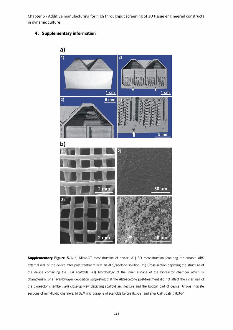
Chapter 5 - Additive manufacturing for high throughput screening of 3D tissue engineered constructs
in dynamic culture
113
4. Supplementary information
Supplementary Figure 5.1- a) Micro-CT reconstruction of device. a1) 3D reconstruction featuring the smooth ABS
external wall of the device after post treatment with an ABS/acetone solution. a2) Cross-section depicting the structure of
the device containing the PLA scaffolds. a3) Morphology of the inner surface of the bioreactor chamber which is
characteristic of a layer-by-layer deposition suggesting that the ABS-acetone post-treatment did not affect the inner wall of
the bioreactor chamber. a4) close-up view depicting scaffold architecture and the bottom part of device. Arrows indicate
sections of mini-fluidic channels. b) SEM micrographs of scaffolds before (b1-b2) and after CaP coating (b3-b4).

Chapter 5 - Additive manufacturing for high throughput screening of 3D tissue engineered constructs
in dynamic culture
114
5. References
1. Langer, R. and J.P. Vacanti, Tissue Engineering. Science, 1993. 260(5110): p. 920-926.
2. Hutmacher, D.W., Scaffold design and fabrication technologies for engineering tissues - state of
the art and future perspectives. Journal of Biomaterials Science-Polymer Edition, 2001. 12(1): p. 107-
124.
3. Martin, I., D. Wendt, and M. Heberer, The role of bioreactors in tissue engineering. Trends in
Biotechnology, 2004. 22(2): p. 80-86.
4. Pereira, D.A. and J.A. Williams, Origin and evolution of high throughput screening. British
Journal of Pharmacology, 2007. 152(1): p. 53-61.
5. Simon, C.G., et al., Fabrication of combinatorial polymer scaffold libraries. Review of Scientific
Instruments, 2007. 78(7).
6. Zapata, P., et al., Quantitative high-throughput screening of osteoblast attachment, spreading,
and proliferation on demixed polymer blend micropatterns. Biomacromolecules, 2007. 8(6): p. 1907-
1917.
7. Nakajima, M., et al., Combinatorial protein display for the cell-based screening of biomaterials
that direct neural stem cell differentiation. Biomaterials, 2007. 28(6): p. 1048-1060.
8. Albrecht, D.R., et al., Photo- and electropatterning of hydrogel-encapsulated living cell arrays.
Lab on a Chip, 2005. 5(1): p. 111-118.
9. Simon, C.G., et al., Combinatorial screening of cell proliferation on poly(D,L-lactic
acid)/poly(D,L-lactic acid) blends. Biomaterials, 2005. 26(34): p. 6906-6915.
10. Kohn, J., New approaches to biomaterials design. Nature Materials, 2004. 3(11): p. 745-747.
11. Anderson, D.G., S. Levenberg, and R. Langer, Nanoliter-scale synthesis of arrayed biomaterials
and application to human embryonic stem cells. Nature Biotechnology, 2004. 22(7): p. 863-866.
12. Cukierman, E., et al., Taking cell-matrix adhesions to the third dimension. Science, 2001.
294(5547): p. 1708-1712.
13. Sun, T., et al., Culture of skin cells in 3D rather than 2D improves their ability to survive
exposure to cytotoxic agents. Journal of Biotechnology, 2006. 122(3): p. 372-381.
14. Birgersdotter, A., R. Sandberg, and I. Ernberg, Gene expression perturbation in vitro - A growing
case for three-dimensional (3D) culture systems. Seminars in Cancer Biology, 2005. 15(5): p. 405-
412.

Chapter 5 - Additive manufacturing for high throughput screening of 3D tissue engineered constructs
in dynamic culture
115
15. Hutmacher, D.W., Biomaterials offer cancer research the third dimension. Nature Materials,
2010. 9(2): p. 90-93.
16. Goncalves, A., et al., Effect of flow perfusion conditions in the chondrogenic differentiation of
bone marrow stromal cells cultured onto starch based biodegradable scaffolds. Acta Biomaterialia,
2011. 7(4): p. 1644-1652.
17. Bancroft, G.N., et al., Fluid flow increases mineralized matrix deposition in 3D perfusion culture
of marrow stromal osteloblasts in a dose-dependent manner. Proceedings of the National Academy of
Sciences of the United States of America, 2002. 99(20): p. 12600-12605.
18. Cartmell, S.H., et al., Effects of medium perfusion rate on cell-seeded three-dimensional bone
constructs in vitro. Tissue Engineering, 2003. 9(6): p. 1197-1203.
19. Goldstein, A.S., et al., Effect of convection on osteoblastic cell growth and function in
biodegradable polymer foam scaffolds. Biomaterials, 2001. 22(11): p. 1279-1288.
20. Grayson, W.L., et al., Effects of Initial Seeding Density and Fluid Perfusion Rate on Formation of
Tissue-Engineered Bone. Tissue Engineering Part A, 2008. 14(11): p. 1809-1820.
21. Han, Y.F., et al., Mechanotransduction and strain amplification in osteocyte cell processes.
Proceedings of the National Academy of Sciences of the United States of America, 2004. 101(47): p.
16689-16694.
22. Marolt, D., et al., Bone and cartilage tissue constructs grown using human bone marrow
stromal cells, silk scaffolds and rotating bioreactors. Biomaterials, 2006. 27(36): p. 6138-6149.
23. Meinel, L., et al., Bone tissue engineering using human mesenchymal stem cells: Effects of
scaffold material and medium flow. Annals of Biomedical Engineering, 2004. 32(1): p. 112-122.
24. Martin, I., T. Smith, and D. Wendt, Bioreactor-based roadmap for the translation of tissue
engineering strategies into clinical products. Trends in Biotechnology, 2009. 27(9): p. 495-502.
25. Sikavitsas, V.I., G.N. Bancroft, and A.G. Mikos, Formation of three-dimensional cell/polymer
constructs for bone tissue engineering in a spinner flask and a rotating wall vessel bioreactor. Journal of
Biomedical Materials Research, 2002. 62(1): p. 136-148.
26. Sikavitsas, V.I., et al., Mineralized matrix deposition by marrow stromal osteoblasts in 3D
perfusion culture increases with increasing fluid shear forces. Proceedings of the National Academy of
Sciences of the United States of America, 2003. 100(25): p. 14683-14688.
27. van den Dolder, J., et al., Flow perfusion culture of marrow stromal osteoblasts in titanium fiber
mesh. Journal of Biomedical Materials Research Part A, 2003. 64A(2): p. 235-241.
Chapter 5 - Additive manufacturing for high throughput screening of 3D tissue engineered constructs
in dynamic culture
116
28. Frohlich, M., et al., Bone Grafts Engineered from Human Adipose-Derived Stem Cells in
Perfusion Bioreactor Culture. Tissue Engineering Part A, 2010. 16(1): p. 179-189.
29. Hollister, S.J., Porous scaffold design for tissue engineering. Nature Materials, 2005. 4(7): p.
518-524.
30. Melchels, F.P.W., et al., Additive manufacturing of tissues and organs. Progress in Polymer
Science, 2012. 37(8): p. 1079-1104.
31. Hutmacher, D.W. and S. Cool, Concepts of scaffold-based tissue engineering-the rationale to
use solid free-form fabrication techniques. Journal of Cellular and Molecular Medicine, 2007. 11(4): p.
654-669.
32. Hutmacher, D.W., M. Sittinger, and M.V. Risbud, Scaffold-based tissue engineering: rationale
for computer-aided design and solid free-form fabrication systems. Trends in Biotechnology, 2004.
22(7): p. 354-362.
33. Grylls, R., Intricate parts from the inside out. Machine Design, 2003. 75(17): p. 56-62.
34. Costa, P.F., et al., Biofabrication of customized bone grafts by combination of additive
manufacturing and bioreactor technologies. Biofabrication, 2013: p. SUBMITTED.
35. Hidalgo-Bastida, L.A., et al., Modeling and design of optimal flow perfusion bioreactors for
tissue engineering applications. Biotechnology and Bioengineering, 2012. 109(4): p. 1095-1099.
36. Alvarez-Barreto, J.F., et al., Flow perfusion improves seeding of tissue engineering scaffolds
with different architectures. Annals of Biomedical Engineering, 2007. 35(3): p. 429-442.
37. Figallo, E., et al., Micro-bioreactor array for controlling cellular microenvironments. Lab on a
Chip, 2007. 7(6): p. 710-719.
38. Gottwald, E., et al., A chip-based platform for the in vitro generation of tissues in three-
dimensional organization. Lab on a Chip, 2007. 7(6): p. 777-785.
39. Yang, J., et al., Enhancing the cell affinity of macroporous poly(L-lactide) cell scaffold by a
convenient surface modification method. Polymer International, 2003. 52(12): p. 1892-1899.
40. Tsuji, H., T. Ishida, and N. Fukuda, Surface hydrophilicity and enzymatic hydrolyzability of
biodegradable polyesters: 1. Effects of alkaline treatment. Polymer International, 2003. 52(5): p. 843-
852.
41. Oliveira, A.L., et al., Nucleation and growth of biomimetic apatite layers on 3D plotted
biodegradable polymeric scaffolds: Effect of static and dynamic coating conditions. Acta Biomaterialia,
2009. 5(5): p. 1626-1638.

Chapter 5 - Additive manufacturing for high throughput screening of 3D tissue engineered constructs
in dynamic culture
117
42. Vaquette, C., et al., Effect of culture conditions and calcium phosphate coating on ectopic bone
formation. Biomaterials, 2013. 34(22): p. 5538-5551.
43. Arafat, M.T., et al., Biomimetic composite coating on rapid prototyped scaffolds for bone tissue
engineering. Acta Biomaterialia, 2011. 7(2): p. 809-820.
44. Araujo, J.V., et al., Surface controlled biomimetic coating of polycaprolactone nanofiber meshes
to be used as bone extracellular matrix analogues. Journal of Biomaterials Science-Polymer Edition,
2008. 19(10): p. 1261-1278.
45. Unadkat, H.V., et al., An algorithm-based topographical biomaterials library to instruct cell fate.
Proceedings of the National Academy of Sciences of the United States of America, 2011. 108(40): p.
16565-16570.
46. Lutolf, M.P., et al., Perturbation of single hematopoietic stem cell fates in artificial niches.
Integrative Biology, 2009. 1(1): p. 59-69.
47. Mei, Y., Microarrayed materials for stem cells. Materials Today, 2012. 15(10): p. 444-452.
48. Jaasma, M.J., N.A. Plunkett, and F.J. O'Brien, Design and validation of a dynamic flow
perfusion bioreactor for use with compliant tissue engineering scaffolds. Journal of Biotechnology,
2008. 133(4): p. 490-496.
49. Janssen, F.W., et al., A perfusion bioreactor system capable of producing clinically relevant
volumes of tissue-engineered bone: In vivo bone formation showing proof of concept. Biomaterials,
2006. 27(3): p. 315-323.
50. Yang, F., J.G.C. Wolke, and J.A. Jansen, Biomimetic calcium phosphate coating on electrospun
poly (epsilon-caprolactone) scaffolds for bone tissue engineering. Chemical Engineering Journal, 2008.
137(1): p. 154-161.


Chapter 6 - Advanced Tissue Engineering Scaffold Design for Regeneration of the Complex
Hierarchical Periodontal Structure
119
Chapter 6
Advanced Tissue Engineering Scaffold Design for Regeneration of the Complex
Hierarchical Periodontal Structure
Abstract
Aim: This study investigated the competence of an osteoinductive biphasic scaffold to simultaneously
regenerate alveolar bone, periodontal ligament and cementum.
Materials and Methods: A biphasic scaffold was built by attaching a fused deposition modeled bone
compartment to a melt electrospun periodontal compartment. The bone compartment was coated with
a calcium phosphate layer for increasing osteoinductivity, seeded with osteoblasts and cultured in vitro
for 6 weeks. The resulting constructs were then complemented with the placement of PDL cell sheets
on the periodontal compartment, attached to a dentin block and subcutaneously implanted into rats for
8 weeks. Scanning electron microscopy, x-ray diffraction, alkaline phosphatase and DNA content
quantification, confocal laser microscopy, micro computerized tomography and histological analysis
were employed to evaluate the scaffold’s performance.
Results: The in vitro study showed that alkaline phosphatase activity was significantly increased in the
CaP coated samples and they also displayed enhanced mineralization. In the in vivo study, significantly
more bone formation was observed in the coated scaffolds. Histological analysis revealed that the large
pore size of the periodontal compartment permitted vascularization of the cell sheets, and periodontal
attachment was achieved at the dentin interface.
Conclusions: This work demonstrates that the combination of cell sheet technology together with an
osteoinductive biphasic scaffold could be utilized to address the limitations of current periodontal
regeneration techniques.
This chapter is based on the following publlication:
Costa P.F., Vaquette C., Zhang Q., Reis R.L., Ivanovski S., Hutmacher D.W., 2013, Advanced tissue
engineering scaffold design for regeneration of the complex hierarchical periodontal structure, Journal of
Clinical periodontology, Accepted for Publication.
Chapter 6 - Advanced Tissue Engineering Scaffold Design for Regeneration of the Complex
Hierarchical Periodontal Structure
120
1. Introduction
Periodontal disease is a chronic inflammatory condition which, if untreated, may ultimately result in
tooth loss due to the destruction of the surrounding soft and hard tissues [1]. Periodontal regeneration
following surgical treatment requires the reconstitution of the complex structure of the periodontium,
which includes formation of periodontal ligament fibers and their insertion into newly formed cementum
on the root surface, as well as regeneration of the adjacent alveolar bone.
Guided Tissue Regeneration (GTR) [2, 3] has emerged as the most widely used regenerative procedure,
and relies on the fulfillment of three main principles: wound stabilization, space maintenance and
selective cell repopulation of the defect. This technique consists of the placement of an occlusive barrier
membrane over the periodontal defect. By this means, cells capable of regenerating the periodontium,
namely periodontal ligament cells as well as osteoblasts and their progenitors, are permitted to infiltrate
the defect, while cell types unable to support regeneration, such as gingival and epithelial cells, are
excluded from the regenerating periodontal defect. By selectively allowing competent cells into the
defect, GTR-based therapy results in a more effective healing when compared to non-selective
procedures, where a poorly or non-organized collagenous scar tissue is observed, characterized by
epithelial downgrowth along the root surface which prevents the formation of periodontal attachment.
However, GTR-based procedures are generally considered unpredictable given the great variability found
in clinical outcomes [4]. Relying merely on the use of a barrier membrane for selectively repopulating
the diseased sites, GTR is greatly constrained by the amount and quality of pre-existing or remaining
healthy tissues in the vicinity of the defect. Similarly, other currently available regenerative procedures
are clinically unpredictable [5], and hence there is a need for new approaches.
Various preclinical studies have shown that tissue engineering concepts incorporating the broad
principles of GTR can achieve enhanced regeneration of the periodontal complex [6-9]. In these studies,
several cell types, such as periodontal ligament fibroblast or mesenchymal precursor cells, were
cultured in vitro in order to form a cell sheet which could be easily harvested with the help of a carrier.
A thick cell layer was obtained by superimposing several cell sheets that were thereafter positioned onto
the root surface in rat or dog models [6, 7, 10-14] or placed onto a dentin block and subcutaneously
implanted in an immuno-compromised rat model [10, 13]. Despite the evidence of histologically
substantiated regeneration in most cases, the handling, placement and visualization of the cell sheets
was found to be difficult and resulted in a lack of biomechanical stability. Indeed, Iwata et al. suggested
Chapter 6 - Advanced Tissue Engineering Scaffold Design for Regeneration of the Complex
Hierarchical Periodontal Structure
121
that the healing process could have been hindered by significant displacement of the implanted cell
sheet, which subsequently compromised the regeneration of the periodontium complex [7].
In our previous work, this issue was successfully addressed by developing a biphasic scaffold made of a
Fused Deposition Modeling (FDM) scaffold (bone compartment) and a solution electrospun membrane
(for the periodontal compartment) which demonstrated significant improvement in the cell sheet
biomechanical stability. The enhanced stability provided by the biphasic scaffold promoted the
attachment of a periodontal-like tissue onto an ectopically implanted dentine block in a rodent model
[15]. Despite the good outcome for periodontal attachment formation, the bone compartment did not
support sufficient bone ingrowth. Owing to the highly hierarchical architecture of the periodontal tissues,
it is necessary that the regenerative events occur in a timely manner so that the ligamentous tissue can
insert into the new cementum on the root surface, as well as the newly formed bone. To this end, the
bone compartment requires enhancement in order to circumvent the aforementioned limitation.
In the early nineties Kokubo at al. developed a solution called Simulated Body Fluid (SBF) which was
utilized for depositing a biomimetic calcium phosphate (CaP) coating on the surface of devices and
implants [16, 17]. This approach has been shown to increase bone related gene expression in various
cell types [18-22] and enhance ectopic bone formation in a rat model [23]. Therefore we report herein
the development of a second generation of biphasic scaffolds designed to incorporate an osteoinductive
bone compartment by the means of a calcium phosphate coating. We further modified the original
concept design by replacing the solution electrospun membrane previously used for the periodontal
compartment with a thin melt electrospun scaffold comprising larger pores adequate for improving
cellular and tissue interaction, especially from a vascularization point of view. The goal of this approach
was to improve the inter-connectivity between the bone and periodontal ligament compartments,
ultimately guiding the perpendicular orientation of newly formed periodontal fibres between regenerated
alveolar bone and root cementum. The performance of this second generation of biphasic scaffold was
evaluated in vitro and in vivo in an athymic rat subcutaneous model.
Chapter 6 - Advanced Tissue Engineering Scaffold Design for Regeneration of the Complex
Hierarchical Periodontal Structure
122
2. Materials and Methods
2.1. Biphasic scaffold fabrication
2.1.1. Bone compartment
Medical grade polycaprolactone (PCL) containing β-tricalcium Phosphate (β-TCP, 20% wt) was utilized
to fabricate composite scaffolds via Fused Deposition Modeling (FDM, Osteopore Inc., Singapore). The
scaffolds measured 100x100x2 mm3 and had 100% interconnectivity, 70% porosity and a 0/90 degrees
lay-down pattern. Prior to use the FDM scaffold block were sectioned with a sharp scalpel blade into
5x5x2 mm3 specimens.
The FDM scaffolds were submitted to a calcium phosphate coating process by successive immersion
into specific reagents and solutions. The procedure consisted of the following steps: immersion in 100%
ethanol for 15 minutes under vacuum, immersion in sodium hydroxide 2 M for 30 min at 37ºC,
multiple rinse-immersions in ultrapure water until a water pH of 7 is reached, immersion in a 10x
simulated body fluid (SBF) solution (solution preparation described elsewhere [24] for 30 min at 37ºC
and immersion in a 0.5 M sodium hydroxide solution for 30 min at 37ºC. Finally the coated scaffolds
were rinsed with ultrapure water and stored in a desiccator until use.
2.1.2. Periodontal compartment
Medical grade polycaprolactone (PCL, Lactel, USA) was electrospun using an in-house melt
electrospinning device [25, 26]. Polymer pellets were loaded into a 2 mL syringe and electrospun at a
temperature of 80°C at a feed rate of 20 µL/h, at 7 kV and at a 4 cm tip to collector distance. Circular
membranes with 8 mm diameter were produced by electrospinning the molten PCL for periods of 4
min onto aluminum foil-covered glass slides placed over the collector.
2.1.3. Assembly of the biphasic scaffold
The assembly of the biphasic scaffolds was performed accordingly to the protocol utilized in our
previous study [15]. Briefly the FDM component was placed 1 cm from a hot plate heated to 300°C for

Chapter 6 - Advanced Tissue Engineering Scaffold Design for Regeneration of the Complex
Hierarchical Periodontal Structure
123
4 seconds and then quickly press-fitted for 10 seconds onto the PCL melt-electrospun membrane. This
heat treatment partially melted the first layer of the FDM component enabling it to strongly bind to the
electrospun scaffold upon cooling and solidification.
2.2. Biphasic scaffold characterization
2.2.1. Scanning electron microscopy (SEM)
SEM was used to assess the scaffold morphology as well as to evaluate the cohesion of the two
compartments. The scaffolds were immersed in liquid nitrogen for 5-10 min and a sharp razor blade
was used to section the structures. The samples were gold coated for 3 min and observed with a FEI
Quanta 200 Environmental SEM operating at 10 kV.
2.2.2. X-ray diffraction
The CaP coating was characterized by X-ray diffraction using a PANalytical X’Pert MPD Powder X-ray
Diffractometer, a Cobalt anode and a 2 theta step size of 0.001.
2.3. In vitro study
2.3.1. Cell isolation and culture
Osteoblast and periodontal ligament explants were obtained from Merino sheep (ovis aries). Animal
ethics approval for this study was granted by the Animal Ethics Committee of the Queensland University
of Technology.
2.3.2. Osteoblasts
Compact bone samples were collected under sterile conditions from the mandible under general
anesthesia with a trephine drill (5 mm diameter), minced, washed with phosphate buffered saline (PBS)
and vortexed 5 times. Bone samples were then incubated with 10 mL of 0.25% trypsin/EDTA for 3 min
at 37°C in a 5% CO2 atmosphere. After trypsin inactivation, samples were washed once again with PBS
Chapter 6 - Advanced Tissue Engineering Scaffold Design for Regeneration of the Complex
Hierarchical Periodontal Structure
124
and transferred in basal culture media (DMEM containing 10% FBS, 1% of penicillin/streptomycin) into
175 cm2 tissue culture flasks. Outgrowth of osteoblasts was observed after 5-7 days. Cells were
expanded and used at the third passage (P3).
2.3.3. Periodontal ligament cells
Two incisors were extracted and placed into a 50 mL tube containing DMEM with 2%
penicillin/streptomycin and 4 µg/mL fungizone. The middle third of the periodontal ligament (PDL) was
subsequently gently removed from the root surface with a scalpel and further sectioned into
approximately 1x1 mm2 pieces. The PDL tissues were placed into a 25 cm2 culture flask which was left
standing upright in an incubator at 37°C and 5% CO2 atmosphere for 30 min to allow tissue adhesion.
After this incubation period, 3 mL of DMEM containing 10% FBS, 1% of penicillin/streptomycin and 0.1
µg/mL fungizone were added and the flask was carefully laid down in the incubator. The first media
change occurred 4 days post extraction. After one week of culture, cells started migrating outwards
from the PDL tissues and reached confluence after 2-3 weeks of culture. The cells were passaged using
0.25% trypsin and further expanded until P3.
2.3.4. Biphasic scaffold seeding and culture
Osteoblasts (200,000 cells in 40 µL of media) were seeded onto the FDM component and allowed to
adhere for 4 hours at 370C in a 5% CO2 atmosphere before the well was filled with media. The biphasic
scaffolds were then turned upside down with the periodontal compartment facing upwards in order to
minimize cell infiltration into the electrospun component. Biphasic scaffolds were further cultured for 6
weeks either in osteogenic media (50 μg/mL ascorbate-2-phosphate, 10 mM β-glycerophosphate, 0.1
μM dexamethasone) or in basal media. The biphasic scaffolds were entirely covered by the medium.
Four groups were created: Non-coated with osteoblasts in basal media (N-N), or in osteogenic media (N-
O), CaP coated scaffold with osteoblasts in basal media (CaP-N), or in osteogenic media (CaP-O).
Osteoblast proliferation and alkaline phosphatase activity were measured at 2, 4 and 6 weeks post
seeding according to the procedure described in the following section.

Chapter 6 - Advanced Tissue Engineering Scaffold Design for Regeneration of the Complex
Hierarchical Periodontal Structure
125
2.3.5. Alkaline phosphatase activity and DNA content
ALP activity was measured from the media in triplicate at different time-points (2, 4 and 6 weeks) after
a 24 hours release period as described in the supplementary information. DNA content was measured
utilizing the Picogreen kit after matrix digestion in a solution of proteinase K (more details can be found
in the Supplementary Information). For the ALP and DNA analyses, 4 biological replicates per group
were used.
2.3.6. Scanning electron microscopy (SEM)
Osteoblasts morphology and distribution into the biphasic scaffold were assessed at 2, 4 and 6 weeks
post-seeding. Samples were fixed in 3% glutaraldehyde until processing. Samples were treated by
sequentially immersing them into 0.1 M cacodylate buffer, 1 % osmium tetroxide in cacodylate buffer,
rinsed in ultrapure water and then dehydrated by immersion into increasingly higher concentration
ethanol solutions. Finally, samples were immersed in hexamethyldisilazane for 60 min, air dried,
mounted onto stubs and gold coated. Samples were observed on a FEI Quanta 200 Environmental SEM
operating at 10 kV.
2.3.7. Confocal laser microscopy
Cellular morphology and orientation were assessed by confocal laser microscopy at 2, 4 and 6 weeks
post-seeding. Samples were washed in PBS and fixed overnight in 4% (w/v) paraformaldehyde
(PFA)/PBS. Samples were then washed in PBS and permeabilized with 0.2 % Triton X100/PBS for
precisely 5 minutes and again washed twice with PBS. F-actin filaments and nuclei were then stained
for 45 minutes with 0.8 U/mL rhodamine 415-conjugated phalloidin and 5 μg/mL 4′-6-diamidino-2-
phenylindole (DAPI) respectively in PBS. Immunofluorescence was visualized and z-stacks acquired
using a confocal microscope (SP5, Leica).

Chapter 6 - Advanced Tissue Engineering Scaffold Design for Regeneration of the Complex
Hierarchical Periodontal Structure
126
2.4. Micro-CT analysis
The effect of the CaP coating along with the in vitro culture conditions upon mineralization was
quantitatively assessed 6 weeks post seeding by micro-computed tomography. Prior to cell seeding
each biphasic scaffold was assigned a number to allow sample tracking. They were thereafter scanned
in a micro-computed tomography (micro-CT) scanner (µCT40, SCANCO Medical AG, Brüttisellen,
Switzerland) at a resolution of 12 µm, a voltage of 45kVp and a current of 177 mA in order to obtain
the signal originating from the scaffold only (called herein scan 1). At the end of the in vitro culture (6
weeks post-seeding) these samples were fixed in 4% paraformaldehyde solution overnight at room
temperature and then washed in PBS and scanned again according to the same parameters in order to
measure the mineralization volume (referred to as scan 2). The true mineralization was quantitatively
determined by subtracting the corresponding initial signal (scan 1) from the mineralization volume at
the end of the culture (scan 2).
2.5. In vivo study
The ability of the biphasic scaffold to facilitate periodontal regeneration including simultaneous bone,
periodontal ligament and cementum regeneration was assessed following insertion in ectopic
(subcutaneous) sites in rats. The osteoblast loaded scaffolds were cultured for 6 weeks and then three
PDL ligament cell sheets were successively placed onto the melt electrospun PCL membrane, thus
creating the periodontal compartment. The following sections describe the cell sheet harvesting along
with the animal implantation.
2.5.1. Harvesting of cell sheets
PDL cells were seeded at 10,000 cells/cm2 in a 24-well plate. The cells were cultured in osteogenic
media and as the cell sheet matured (after 7 days of culture), it started to contract and detach from the
well. Following a procedure used in previous work [15], three PDL cell sheets were then harvested
using the electrospun component of the biphasic scaffold (see Supplementary Information).
Chapter 6 - Advanced Tissue Engineering Scaffold Design for Regeneration of the Complex
Hierarchical Periodontal Structure
127
2.5.2. Dentin slices and scaffold assembly
One millimeter thick dentin slices were prepared from sheep teeth and adjusted to the size of the
biphasic scaffolds. The assembly of the biphasic scaffolds onto dentin blocks was performed under
sterile conditions and sutures were used to keep the biphasic scaffold on top of the dentin slice.
Thereafter the samples were immersed in media for 2 hours in order to allow for cell sheet adhesion
onto the dentin surface. Notches on the dentin slices were created in order to prevent the sutures from
sliding off, thus ensuring high stability of the scaffold.
2.5.3. Subcutaneous implantation
Animal ethics approval for the use of athymic nude rats in this experiment was granted by the Animal
Ethics Committee of Griffith University. Five 8-week old male rats (Animal Resources Centre, Canning
Vale, WA, Australia) were used. The animals were anaesthetized with isoflurane. Six small incisions
were made longitudinally along the central line of the shaved dorsal area, approximately 2 cm apart,
and subcutaneous pockets were made with surgical scissors. Six different groups of biphasic scaffolds
were implanted for 8 weeks. The groups consisted of 1) non coated biphasic scaffolds combined with
cell sheets (n=5) or 2) without cell sheets (n=5); 3) non-coated biphasic scaffolds with osteoblasts
cultured in basal media (n=5) or 4) in osteogenic media (n=5); 5) CaP-coated scaffolds with osteoblasts
cultured in basal media (n=5) or 6) in osteogenic media (n=5). Each individual pocket held one scaffold
and the incisions were closed with 5/0 silk sutures. Therefore, 4 groups out of 6 did not receive the
CaP coating. The animals were sacrificed after eight weeks and the implants were retrieved and fixed in
4% paraformaldehyde in PBS at pH 7.4 for further analysis.
2.5.4. Micro-CT analysis
To determine the efficacy of the biphasic scaffold in regard to mineralized tissue formation, the retrieved
samples were analyzed by micro-CT according to the parameters described in section 2.3. Here again
the intrinsic signal originating from the scaffold was measured prior to in vitro culture and subtracted
from the signal obtained when scanning the samples 8 weeks post implantation. This permitted the
precise measurement of the amount of newly formed bone. To validate the in vivo mineralization within
the PCL scaffold, the attached dentin block was excluded from the scan and the average density of

Chapter 6 - Advanced Tissue Engineering Scaffold Design for Regeneration of the Complex
Hierarchical Periodontal Structure
128
mineralization against a hydroxyapatite standard (supplied by Scanco) was measured by the micro-CT
system software.
2.5.5. Histology
Samples were decalcified in 10% EDTA at pH 7.4 for 3 months at 4 °C with a weekly change of solution
and subsequently embedded in paraffin. Sections near the central area of the implants were used for
the haematoxylin and eosin (H&E) staining. We defined periodontal-like attachment as direct contact of
the connective tissue (or cell sheets) with the dentine slice. The number of specimens demonstrating
periodontal-like attachment in each group (with or without cell sheets) was calculated and compared to
the total number of samples within the same group.
Figure 6.1 – Graphical illustration of the biomimetic coating procedure, the fabrication of the biphasic scaffold, cell
seeding, subsequent in vitro culture and in vivo implantation of the cellular constructs. a) and b) harvesting and placement
of cell sheets on the periodontal compartment. c) and d) positioning of the construct to a dentin block.

Chapter 6 - Advanced Tissue Engineering Scaffold Design for Regeneration of the Complex
Hierarchical Periodontal Structure
129
2.6. Statistical analysis
The statistical analysis was performed using a Shapiro-Wilk normality test and one-way ANOVA followed
by a Tukey HSD post-hoc test. p< 0.05 was considered as statistically significant.
3. Results
3.1. Scaffold morphology
Figure 6.1 depicts the global strategy developed in this study from the scaffold fabrication and assembly
to the in vivo implantation. The bone compartment was coated with a layer of calcium phosphate
homogenously distributed on the polymer struts. This surface modification displayed the typical features
of biomimetic calcium phosphate coating, that is formation of cauliflower-like structures as seen in
Figure 6.2.b. The NaOH pre-treatment resulted in exposure of the β-TCP particles on the surface of the
PCL struts. This enabled the creation of specific nucleation sites for the deposition of the CaP coating.
Indeed, the calcium phosphate preferentially nucleated onto the TCP particles (probably due the higher
affinity and the lower surface energy) and then spread over the surface on the PCL strut. The resulting
CaP coating was composed of a mixture of Di-Calcium Phosphate Dihydrate (DCPD) and carbonate
apatite, however the NaOH post treatment was capable of removing the more soluble phase (DCPD).
Indeed, the XRD analysis (Figure 6.2.e.) revealed that the intensity of the peaks corresponding to DCPD
was reduced after the post-treatment while the intensity of the peaks corresponding to carbonate
hydroxylapatite was increased. This indicates that the CaP deposits on the polymeric strut had good
physical stability, which is necessary for osteogenesis.Upon sectioning of the bone compartment, it was
possible to access the approximate thickness of the coating. The SBF immersion resulted in the
deposition of a 600-800 nm coating.
The periodontal compartment consisted of a melt electrospun scaffold composed of randomly
orientated PCL fibers. As seen in Figure 6.2.d, fiber fusion occurred at different locations, which created
a concentric ring pattern during the fabrication process. The fiber diameter was around 10 to 15 µm
which resulted in the formation of a fully interconnected porous structure, with pore sizes ranging from
100 to 400 µm (as estimated by SEM). The assembly of the biphasic scaffold was performed through a
press-fit methodology by compressing the partially fused CaP coated bone compartment (FDM scaffold)
onto the periodontal compartment (melt electrospun mesh) for several seconds. Upon solidification of

Chapter 6 - Advanced Tissue Engineering Scaffold Design for Regeneration of the Complex
Hierarchical Periodontal Structure
130
Figure 6.2 – Scanning Electron Microscopy and X-ray diffraction analysis of scaffolds. a) and c) Cross-sectional views of
scaffolds. b) CaP-coated surface of FDM scaffold. d) Melt electrospun mesh. e) X-ray diffraction analysis of surface of non-
coated and CaP-coated scaffold strut. * is hydroxyapatite and # is DCPD.
Chapter 6 - Advanced Tissue Engineering Scaffold Design for Regeneration of the Complex
Hierarchical Periodontal Structure
131
the partially molten bone compartment, both scaffold remained fused and firmly attached together. As
seen in Figure 6.2 the scaffold assembly was not detrimental to the physical integrity of each individual
component.
3.2. In vitro study
3.2.1. Cell imaging
Osteoblasts were seeded and cultured in vitro in the biphasic scaffold’s bone compartment for a total
period of 6 weeks. Confocal laser microscopy and SEM imaging (Figure 6.3 and Supplementary Figures
6.1 and 6.2) revealed that 2 weeks post-seeding cells were homogenously distributed around the bone
compartment’s polymer struts and acquired a spindle-like shape. Noticeable differences were observed
between osteoblasts grown in the groups cultured in basal media (N-N and CaP-N) and the ones under
osteogenic induction (N-O and CaP-O) as the latter were capable of spanning between the polymer
struts and therefore started filling the macroscopic pores of the bone compartment. Notably, the
periodontal compartment was also infiltrated by the osteoblasts as early as 2 weeks post seeding
regardless of the culture conditions. The cells entirely filled the melt electrospun pores after 2 weeks of
osteogenic induction and formed a dense cell layer on the surface of the periodontal compartment. A
similar effect was observed for the cell in basal media albeit at a later time point (6 weeks post
seeding). Scanning Electron Microscopy also revealed that the osteoblasts accumulated at the interface
of both compartments when cultured under osteogenic induction (second and fourth column).
3.2.2. DNA content and Alkaline Phosphatase activity
Cell proliferation was assessed by DNA quantification. At two weeks post-seeding, a significantly higher
amount of DNA was found in the groups under osteogenic induction but this effect was less pronounced
for the two later time points (Figure 6.4.A.). It was also observed that the osteoblasts in basal media,
seeded onto the non-coated scaffold (N-N group) supported significant cell proliferation at 6 weeks post-
seeding, whereas the DNA remained constant for the other experimental groups excepted for the N-O
group in which a gradual but significant decrease was observed (Figure 6.4.B.). The reason for this
finding is unclear but it may be linked to a lack of diffusion of oxygen and nutrient in the depth of the
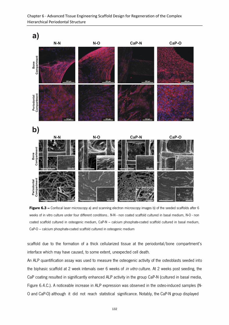
Chapter 6 - Advanced Tissue Engineering Scaffold Design for Regeneration of the Complex
Hierarchical Periodontal Structure
132
scaffold due to the formation of a thick cellularized tissue at the periodontal/bone compartment’s
interface which may have caused, to some extent, unexpected cell death.
An ALP quantification assay was used to measure the osteogenic activity of the osteoblasts seeded into
the biphasic scaffold at 2 week intervals over 6 weeks of in vitro culture. At 2 weeks post seeding, the
CaP coating resulted in significantly enhanced ALP activity in the group CaP-N (cultured in basal media,
Figure 6.4.C.). A noticeable increase in ALP expression was observed in the osteo-induced samples (N-
O and CaP-O) although it did not reach statistical significance. Notably, the CaP-N group displayed
Figure 6.3 – Confocal laser microscopy a) and scanning electron microscopy images b) of the seeded scaffolds after 6
weeks of in vitro culture under four different conditions.. N-N - non coated scaffold cultured in basal medium, N-O - non
coated scaffold cultured in osteogenic medium, CaP-N – calcium phosphate-coated scaffold cultured in basal medium,
CaP-O – calcium phosphate-coated scaffold cultured in osteogenic medium
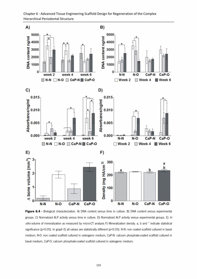
Chapter 6 - Advanced Tissue Engineering Scaffold Design for Regeneration of the Complex
Hierarchical Periodontal Structure
133
Figure 6.4 - Biological characterization. A) DNA content versus time in culture. B) DNA content versus experimental
groups. C) Normalized ALP activity versus time in culture. D) Normalized ALP activity versus experimental groups. E) In
vitro volume of mineralization as measured by micro-CT analysis F) Mineralization density. a, b and * indicate statistical
significance (p<0.05). In graph E) all values are statistically different (p<0.05). N-N: non coated scaffold cultured in basal
medium, N-O: non coated scaffold cultured in osteogenic medium, CaP-N: calcium phosphate-coated scaffold cultured in
basal medium, CaP-O: calcium phosphate-coated scaffold cultured in osteogenic medium.
Chapter 6 - Advanced Tissue Engineering Scaffold Design for Regeneration of the Complex
Hierarchical Periodontal Structure
134
higher ALP expression at 2 weeks post seeding than the osteoblasts cultured in osteogenic media,
exemplifying the efficacy of the CaP coating at enhancing ALP activity. The synergetic effect of the
coating and the osteogenic induction was more pronounced at 4 weeks post seeding where the CaP-O
group induced significantly higher ALP expression than any other groups. ALP activity was significantly
up-regulated at 6 weeks post-seeding in both groups with osteogenic media when compared the
samples in basal media (N-N and CaPN). However no statistical difference was found between N-O and
CaP-O at this time point. Figure 6.4.D. depicts ALP activity for each group throughout the time course
of the in vitro culture, and it can be observed that ALP activity remained constant in the samples
cultured in basal media whereas the osteogenic induction resulted in a gradual and significant increase
in this parameter.
3.2.3. Micro-computed tomography
The volume of mineralized matrix deposited by the cells during the 6 weeks of in vitro culture was
quantified by micro-CT and is shown in Figure 6.4.E. It was observed that the CaP coating clearly
resulted in enhanced mineralization within the scaffolds regardless of the culture conditions. More
importantly, it showed that osteogenic induction was the most potent signal for secreting mineralized
matrix as both, N-O and CaP-O groups displayed much higher mineralization volume than the
corresponding groups cultured in basal media. Indeed, mineralization in N-N samples remained within
the noise level, whereas 1.9 and 2.5 mm3 of mineralized matrix was produced for N-O and CaP-O
respectively. This corroborated the ALP activity profile observed in these groups and confirmed the
beneficial effect of CaP coating on the deposition of mineralized matrix. The average mineralization
density, as assessed from the micro-CT scan, provided insights into the mineralized matrix maturation,
whereby higher density is associated with a more mature matrix. However no significant differences
were observed between CaPO and NO suggesting that the mineralized matrix was equivalent “quality”.
3.3. In vivo study
After an uneventful 8 weeks post-operative period, the animals were sacrificed and the constructs
collected. Good tissue integration into the subcutaneous pocket was observed and no acute foreign
body reaction or infections were observed.
The amount of newly formed bone in the constructs was analyzed using micro CT (Figure 6.5.A.). The
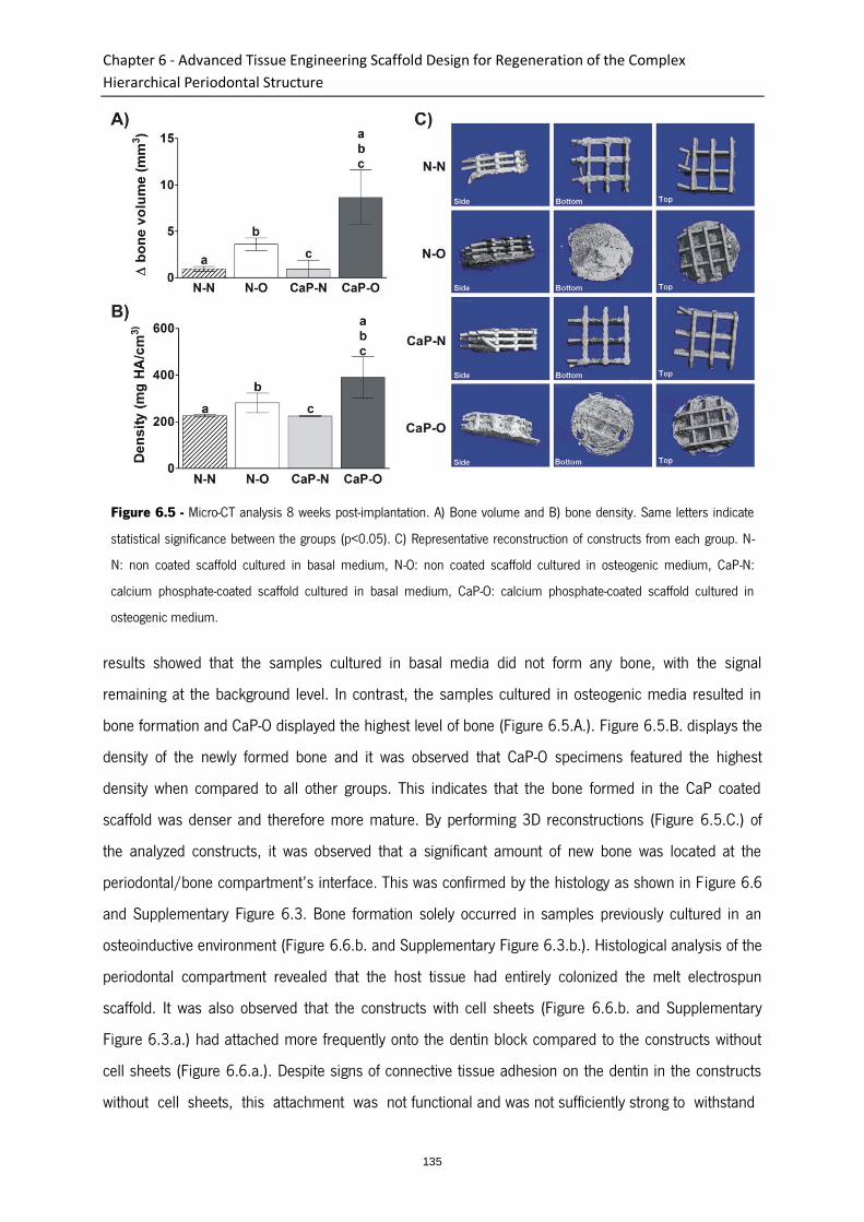
Chapter 6 - Advanced Tissue Engineering Scaffold Design for Regeneration of the Complex
Hierarchical Periodontal Structure
135
Figure 6.5 - Micro-CT analysis 8 weeks post-implantation. A) Bone volume and B) bone density. Same letters indicate
statistical significance between the groups (p<0.05). C) Representative reconstruction of constructs from each group. N-
N: non coated scaffold cultured in basal medium, N-O: non coated scaffold cultured in osteogenic medium, CaP-N:
calcium phosphate-coated scaffold cultured in basal medium, CaP-O: calcium phosphate-coated scaffold cultured in
osteogenic medium.
results showed that the samples cultured in basal media did not form any bone, with the signal
remaining at the background level. In contrast, the samples cultured in osteogenic media resulted in
bone formation and CaP-O displayed the highest level of bone (Figure 6.5.A.). Figure 6.5.B. displays the
density of the newly formed bone and it was observed that CaP-O specimens featured the highest
density when compared to all other groups. This indicates that the bone formed in the CaP coated
scaffold was denser and therefore more mature. By performing 3D reconstructions (Figure 6.5.C.) of
the analyzed constructs, it was observed that a significant amount of new bone was located at the
periodontal/bone compartment’s interface. This was confirmed by the histology as shown in F igure 6.6
and Supplementary Figure 6.3. Bone formation solely occurred in samples previously cultured in an
osteoinductive environment (Figure 6.6.b. and Supplementary Figure 6.3.b.). Histological analysis of the
periodontal compartment revealed that the host tissue had entirely colonized the melt electrospun
scaffold. It was also observed that the constructs with cell sheets (Figure 6.6.b. and Supplementary
Figure 6.3.a.) had attached more frequently onto the dentin block compared to the constructs without
cell sheets (Figure 6.6.a.). Despite signs of connective tissue adhesion on the dentin in the constructs
without cell sheets, this attachment was not functional and was not sufficiently strong to withstand

Chapter 6 - Advanced Tissue Engineering Scaffold Design for Regeneration of the Complex
Hierarchical Periodontal Structure
136
Figure 6.6 - Representative H&E (a-c) and immune (d) staining images of implanted biphasic scaffolds. a) Reduced
tissue attachment on the dentin without cell sheets. b) Bone formation in the CaP-coated samples cultured in osteogenic
media prior to implantation. d) Representative section depicting the vascularization in the periodontal compartment. c)
Tissue orientation provided by the periodontal compartment architecture. DB- dentin block, BO- bone, VE- vessel, SC-
Spaces formed by FDM scaffold’s struts, MES indicates melt electrospun scaffold and thin arrows indicate single melt
electrospun fibers. Triangular arrows indicate periodontal ligament. Scales are 100 µm.
histological processing and sectioning hence generating a space between these two elements. The
percentage of attachment for each condition was calculated (Table 6.1) and showed that most of the
constructs with cell sheets (4/5-80%) were able to attach as opposed to 1/5-20% for the constructs
without cell sheets. Blood vessels penetrated not only throughout the bone compartment (FDM scaffold)
(Supplementary Figure 6.3.c. and e.), but also throughout the periodontal compartment (Figure 6.6.d.
and Supplementary Figure 6.3.d.). Blood vessels were found in close vicinity of the implanted cell
sheets (Figure 6.6.d. and Supplementary Figure 6.3.d.), which may have a significant impact on cell
sheet survival and subsequent tissue remodeling. It is also noteworthy that, due to the intrinsic
architecture of the melt electrospun scaffold, which consisted of superimposed concentrically oriented
Table 6.1 - Quantification of tissue attachment on the dentin block showing that attachment to the dentin block is more
effective in the presence (80%) than in absence (20%) of cell sheet.
With Cell sheet (%) Without Cell sheet (%)
Percentage of samples
showing attachment to
dentin
80 20
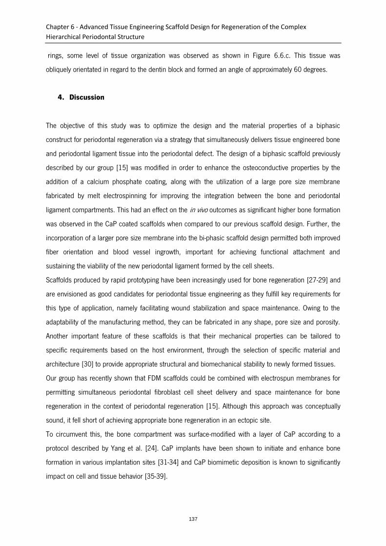
Chapter 6 - Advanced Tissue Engineering Scaffold Design for Regeneration of the Complex
Hierarchical Periodontal Structure
137
rings, some level of tissue organization was observed as shown in Figure 6.6.c. This tissue was
obliquely orientated in regard to the dentin block and formed an angle of approximately 60 degrees.
4. Discussion
The objective of this study was to optimize the design and the material properties of a biphasic
construct for periodontal regeneration via a strategy that simultaneously delivers tissue engineered bone
and periodontal ligament tissue into the periodontal defect. The design of a biphasic scaffold previously
described by our group [15] was modified in order to enhance the osteoconductive properties by the
addition of a calcium phosphate coating, along with the utilization of a large pore size membrane
fabricated by melt electrospinning for improving the integration between the bone and periodontal
ligament compartments. This had an effect on the in vivo outcomes as significant higher bone formation
was observed in the CaP coated scaffolds when compared to our previous scaffold design. Further, the
incorporation of a larger pore size membrane into the bi-phasic scaffold design permitted both improved
fiber orientation and blood vessel ingrowth, important for achieving functional attachment and
sustaining the viability of the new periodontal ligament formed by the cell sheets.
Scaffolds produced by rapid prototyping have been increasingly used for bone regeneration [27-29] and
are envisioned as good candidates for periodontal tissue engineering as they fulfill key requirements for
this type of application, namely facilitating wound stabilization and space maintenance. Owing to the
adaptability of the manufacturing method, they can be fabricated in any shape, pore size and porosity.
Another important feature of these scaffolds is that their mechanical properties can be tailored to
specific requirements based on the host environment, through the selection of specific material and
architecture [30] to provide appropriate structural and biomechanical stability to newly formed tissues.
Our group has recently shown that FDM scaffolds could be combined with electrospun membranes for
permitting simultaneous periodontal fibroblast cell sheet delivery and space maintenance for bone
regeneration in the context of periodontal regeneration [15]. Although this approach was conceptually
sound, it fell short of achieving appropriate bone regeneration in an ectopic site.
To circumvent this, the bone compartment was surface-modified with a layer of CaP according to a
protocol described by Yang et al. [24]. CaP implants have been shown to initiate and enhance bone
formation in various implantation sites [31-34] and CaP biomimetic deposition is known to significantly
impact on cell and tissue behavior [35-39].
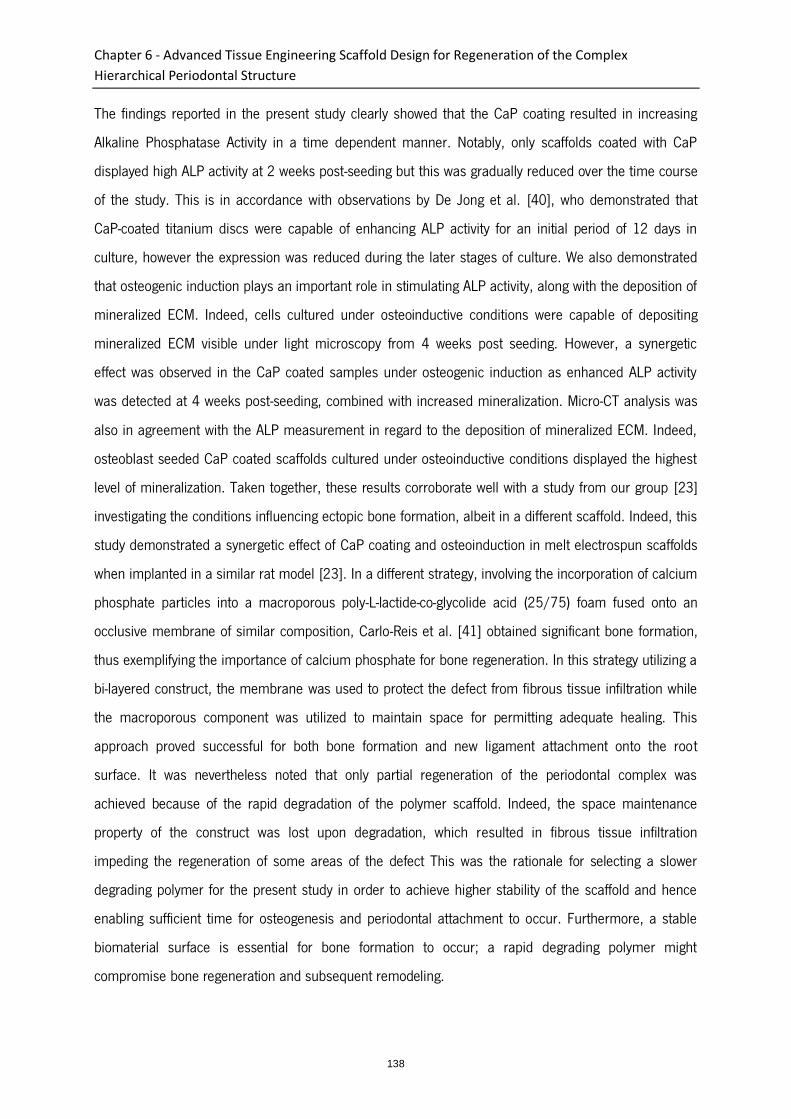
Chapter 6 - Advanced Tissue Engineering Scaffold Design for Regeneration of the Complex
Hierarchical Periodontal Structure
138
The findings reported in the present study clearly showed that the CaP coating resulted in increasing
Alkaline Phosphatase Activity in a time dependent manner. Notably, only scaffolds coated with CaP
displayed high ALP activity at 2 weeks post-seeding but this was gradually reduced over the time course
of the study. This is in accordance with observations by De Jong et al. [40], who demonstrated that
CaP-coated titanium discs were capable of enhancing ALP activity for an initial period of 12 days in
culture, however the expression was reduced during the later stages of culture. We also demonstrated
that osteogenic induction plays an important role in stimulating ALP activity, along with the deposition of
mineralized ECM. Indeed, cells cultured under osteoinductive conditions were capable of depositing
mineralized ECM visible under light microscopy from 4 weeks post seeding. However, a synergetic
effect was observed in the CaP coated samples under osteogenic induction as enhanced ALP activity
was detected at 4 weeks post-seeding, combined with increased mineralization. Micro-CT analysis was
also in agreement with the ALP measurement in regard to the deposition of mineralized ECM. Indeed,
osteoblast seeded CaP coated scaffolds cultured under osteoinductive conditions displayed the highest
level of mineralization. Taken together, these results corroborate well with a study from our group [23]
investigating the conditions influencing ectopic bone formation, albeit in a different scaffold. Indeed, this
study demonstrated a synergetic effect of CaP coating and osteoinduction in melt electrospun scaffolds
when implanted in a similar rat model [23]. In a different strategy, involving the incorporation of calcium
phosphate particles into a macroporous poly-L-lactide-co-glycolide acid (25/75) foam fused onto an
occlusive membrane of similar composition, Carlo-Reis et al. [41] obtained significant bone formation,
thus exemplifying the importance of calcium phosphate for bone regeneration. In this strategy utilizing a
bi-layered construct, the membrane was used to protect the defect from fibrous tissue infiltration while
the macroporous component was utilized to maintain space for permitting adequate healing. This
approach proved successful for both bone formation and new ligament attachment onto the root
surface. It was nevertheless noted that only partial regeneration of the periodontal complex was
achieved because of the rapid degradation of the polymer scaffold. Indeed, the space maintenance
property of the construct was lost upon degradation, which resulted in fibrous tissue infiltration
impeding the regeneration of some areas of the defect This was the rationale for selecting a slower
degrading polymer for the present study in order to achieve higher stability of the scaffold and hence
enabling sufficient time for osteogenesis and periodontal attachment to occur. Furthermore, a stable
biomaterial surface is essential for bone formation to occur; a rapid degrading polymer might
compromise bone regeneration and subsequent remodeling.
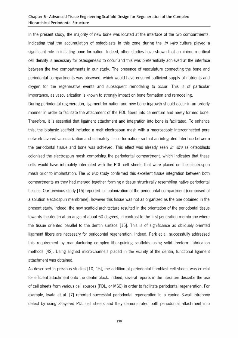
Chapter 6 - Advanced Tissue Engineering Scaffold Design for Regeneration of the Complex
Hierarchical Periodontal Structure
139
In the present study, the majority of new bone was located at the interface of the two compartments,
indicating that the accumulation of osteoblasts in this zone during the in vitro culture played a
significant role in initiating bone formation. Indeed, other studies have shown that a minimum critical
cell density is necessary for osteogenesis to occur and this was preferentially achieved at the interface
between the two compartments in our study. The presence of vasculature connecting the bone and
periodontal compartments was observed, which would have ensured sufficient supply of nutrients and
oxygen for the regenerative events and subsequent remodeling to occur. This is of particular
importance, as vascularization is known to strongly impact on bone formation and remodeling.
During periodontal regeneration, ligament formation and new bone ingrowth should occur in an orderly
manner in order to facilitate the attachment of the PDL fibers into cementum and newly formed bone.
Therefore, it is essential that ligament attachment and integration into bone is facilitated. To enhance
this, the biphasic scaffold included a melt electrospun mesh with a macroscopic interconnected pore
network favored vascularization and ultimately tissue formation, so that an integrated interface between
the periodontal tissue and bone was achieved. This effect was already seen in vitro as osteoblasts
colonized the electrospun mesh comprising the periodontal compartment, which indicates that these
cells would have intimately interacted with the PDL cell sheets that were placed on the electrospun
mash prior to implantation. The in vivo study confirmed this excellent tissue integration between both
compartments as they had merged together forming a tissue structurally resembling native periodontal
tissues. Our previous study [15] reported full colonization of the periodontal compartment (composed of
a solution electrospun membrane), however this tissue was not as organized as the one obtained in the
present study. Indeed, the new scaffold architecture resulted in the orientation of the periodontal tissue
towards the dentin at an angle of about 60 degrees, in contrast to the first generation membrane where
the tissue oriented parallel to the dentin surface [15]. This is of significance as obliquely oriented
ligament fibers are necessary for periodontal regeneration. Indeed, Park et al. successfully addressed
this requirement by manufacturing complex fiber-guiding scaffolds using solid freeform fabrication
methods [42]. Using aligned micro-channels placed in the vicinity of the dentin, functional ligament
attachment was obtained.
As described in previous studies [10, 15], the addition of periodontal fibroblast cell sheets was crucial
for efficient attachment onto the dentin block. Indeed, several reports in the literature describe the use
of cell sheets from various cell sources (PDL, or MSC) in order to facilitate periodontal regeneration. For
example, Iwata et al. [7] reported successful periodontal regeneration in a canine 3-wall intrabony
defect by using 3-layered PDL cell sheets and they demonstrated both periodontal attachment into
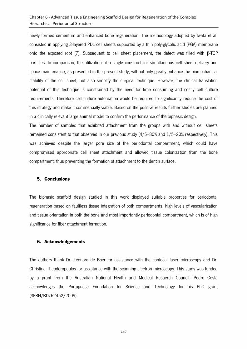
Chapter 6 - Advanced Tissue Engineering Scaffold Design for Regeneration of the Complex
Hierarchical Periodontal Structure
140
newly formed cementum and enhanced bone regeneration. The methodology adopted by Iwata et al.
consisted in applying 3-layered PDL cell sheets supported by a thin poly-glycolic acid (PGA) membrane
onto the exposed root [7]. Subsequent to cell sheet placement, the defect was filled with β-TCP
particles. In comparison, the utilization of a single construct for simultaneous cell sheet delivery and
space maintenance, as presented in the present study, will not only greatly enhance the biomechanical
stability of the cell sheet, but also simplify the surgical technique. However, the clinical translation
potential of this technique is constrained by the need for time consuming and costly cell culture
requirements. Therefore cell culture automation would be required to significantly reduce the cost of
this strategy and make it commercially viable. Based on the positive results further studies are planned
in a clinically relevant large animal model to confirm the performance of the biphasic design.
The number of samples that exhibited attachment from the groups with and without cell sheets
remained consistent to that observed in our previous study (4/5=80% and 1/5=20% respectively). This
was achieved despite the larger pore size of the periodontal compartment, which could have
compromised appropriate cell sheet attachment and allowed tissue colonization from the bone
compartment, thus preventing the formation of attachment to the dentin surface.
5. Conclusions
The biphasic scaffold design studied in this work displayed suitable properties for periodontal
regeneration based on faultless tissue integration of both compartments, high levels of vascularization
and tissue orientation in both the bone and most importantly periodontal compartment, which is of high
significance for fiber attachment formation.
6. Acknowledgements
The authors thank Dr. Leonore de Boer for assistance with the confocal laser microscopy and Dr.
Christina Theodoropoulos for assistance with the scanning electron microscopy. This study was funded
by a grant from the Australian National Health and Medical Resaerch Council. Pedro Costa
acknowledges the Portuguese Foundation for Science and Technology for his PhD grant
(SFRH/BD/62452/2009).
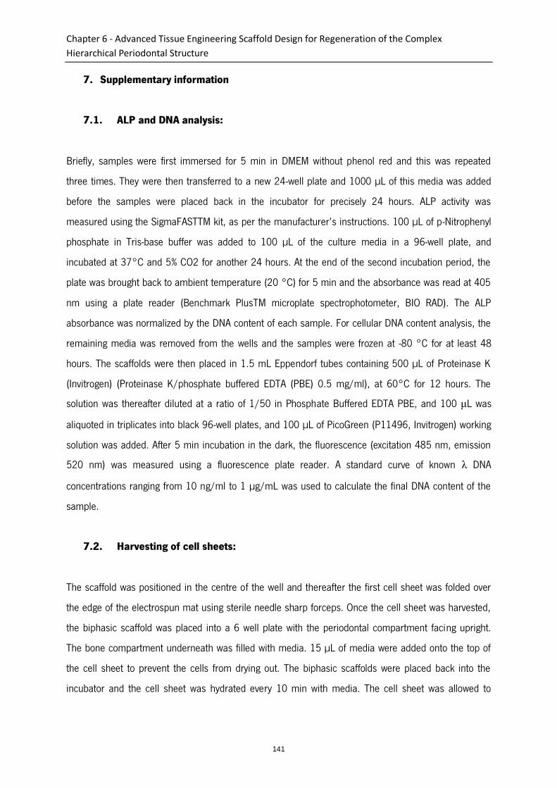
Chapter 6 - Advanced Tissue Engineering Scaffold Design for Regeneration of the Complex
Hierarchical Periodontal Structure
141
7. Supplementary information
7.1. ALP and DNA analysis:
Briefly, samples were first immersed for 5 min in DMEM without phenol red and this was repeated
three times. They were then transferred to a new 24-well plate and 1000 µL of this media was added
before the samples were placed back in the incubator for precisely 24 hours. ALP activity was
measured using the SigmaFASTTM kit, as per the manufacturer’s instructions. 100 µL of p-Nitrophenyl
phosphate in Tris-base buffer was added to 100 µL of the culture media in a 96-well plate, and
incubated at 37°C and 5% CO2 for another 24 hours. At the end of the second incubation period, the
plate was brought back to ambient temperature (20 °C) for 5 min and the absorbance was read at 405
nm using a plate reader (Benchmark PlusTM microplate spectrophotometer, BIO RAD). The ALP
absorbance was normalized by the DNA content of each sample. For cellular DNA content analysis, the
remaining media was removed from the wells and the samples were frozen at -80 °C for at least 48
hours. The scaffolds were then placed in 1.5 mL Eppendorf tubes containing 500 µL of Proteinase K
(Invitrogen) (Proteinase K/phosphate buffered EDTA (PBE) 0.5 mg/ml), at 60°C for 12 hours. The
solution was thereafter diluted at a ratio of 1/50 in Phosphate Buffered EDTA PBE, and 100 μL was
aliquoted in triplicates into black 96-well plates, and 100 µL of PicoGreen (P11496, Invitrogen) working
solution was added. After 5 min incubation in the dark, the fluorescence (excitation 485 nm, emission
520 nm) was measured using a fluorescence plate reader. A standard curve of known λ DNA
concentrations ranging from 10 ng/ml to 1 µg/mL was used to calculate the final DNA content of the
sample.
7.2. Harvesting of cell sheets:
The scaffold was positioned in the centre of the well and thereafter the first cell sheet was folded over
the edge of the electrospun mat using sterile needle sharp forceps. Once the cell sheet was harvested,
the biphasic scaffold was placed into a 6 well plate with the periodontal compartment facing upright.
The bone compartment underneath was filled with media. 15 µL of media were added onto the top of
the cell sheet to prevent the cells from drying out. The biphasic scaffolds were placed back into the
incubator and the cell sheet was hydrated every 10 min with media. The cell sheet was allowed to
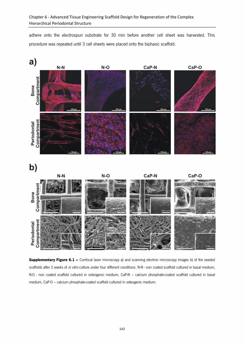
Chapter 6 - Advanced Tissue Engineering Scaffold Design for Regeneration of the Complex
Hierarchical Periodontal Structure
142
adhere onto the electrospun substrate for 30 min before another cell sheet was harvested. This
procedure was repeated until 3 cell sheets were placed onto the biphasic scaffold.
Supplementary Figure 6.1 – Confocal laser microscopy a) and scanning electron microscopy images b) of the seeded
scaffolds after 2 weeks of in vitro culture under four different conditions. N-N - non coated scaffold cultured in basal medium,
N-O - non coated scaffold cultured in osteogenic medium, CaP-N – calcium phosphate-coated scaffold cultured in basal
medium, CaP-O – calcium phosphate-coated scaffold cultured in osteogenic medium.

Chapter 6 - Advanced Tissue Engineering Scaffold Design for Regeneration of the Complex
Hierarchical Periodontal Structure
143
Supplementary Figure 6.2 – Confocal laser microscopy a) and scanning electron microscopy images b) of the seeded
scaffolds after 4 weeks of in vitro culture under four different conditions. N-N - non coated scaffold cultured in basal medium,
N-O - non coated scaffold cultured in osteogenic medium, CaP-N – calcium phosphate-coated scaffold cultured in basal
medium, CaP-O – calcium phosphate-coated scaffold cultured in osteogenic medium.
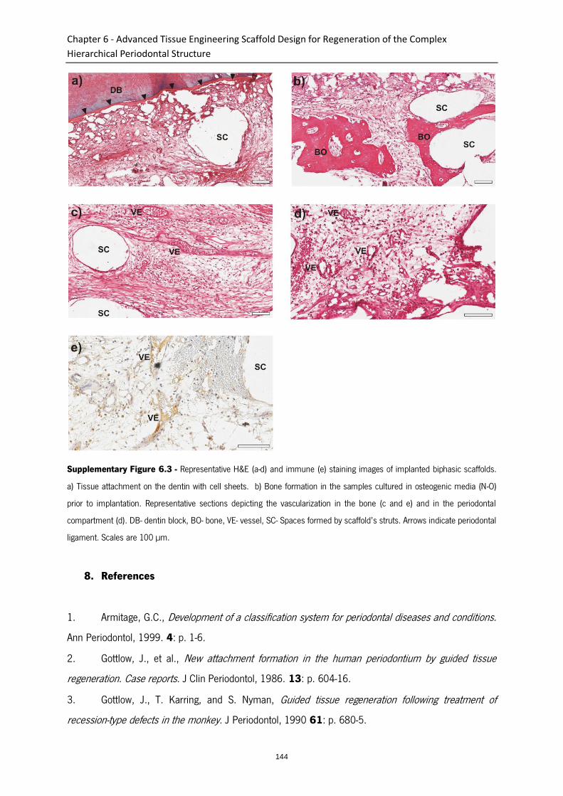
Chapter 6 - Advanced Tissue Engineering Scaffold Design for Regeneration of the Complex
Hierarchical Periodontal Structure
144
Supplementary Figure 6.3 - Representative H&E (a-d) and immune (e) staining images of implanted biphasic scaffolds.
a) Tissue attachment on the dentin with cell sheets. b) Bone formation in the samples cultured in osteogenic media (N-O)
prior to implantation. Representative sections depicting the vascularization in the bone (c and e) and in the periodontal
compartment (d). DB- dentin block, BO- bone, VE- vessel, SC- Spaces formed by scaffold’s struts. Arrows indicate periodontal
ligament. Scales are 100 µm.
8. References
1. Armitage, G.C., Development of a classification system for periodontal diseases and conditions.
Ann Periodontol, 1999. 4: p. 1-6.
2. Gottlow, J., et al., New attachment formation in the human periodontium by guided tissue
regeneration. Case reports. J Clin Periodontol, 1986. 13: p. 604-16.
3. Gottlow, J., T. Karring, and S. Nyman, Guided tissue regeneration following treatment of
recession-type defects in the monkey. J Periodontol, 1990 61: p. 680-5.
Chapter 6 - Advanced Tissue Engineering Scaffold Design for Regeneration of the Complex
Hierarchical Periodontal Structure
145
4. Needleman, I., et al., Guided tissue regeneration for periodontal infra-bony defects. Cochrane
Database of Systematic Reviews, 2006. 2.
5. Ivanovski, S., Periodontal Regeneration. Aust Dent J, 2009. 54: p. S118-S128.
6. Akizuki, T., et al., Application of periodontal ligament cell sheet for periodontal regeneration: a
pilot study in beagle dogs. J Periodontal Res, 2005. 40: p. 245-251.
7. Iwata, T., et al., Periodontal regeneration with multi-layered periodontal ligament-derived cell
sheets in a canine model. Biomaterials 2009. 30: p. 2716-2723.
8. Vaquette, C. and J. Cooper-White, The use of an electrostatic lens to enhance the efficiency of
the electrospinning process. Cell and Tissue Research, 2012. 347(3): p. 815-826.
9. Dan, H., et al., The influence of cellular source on periodontal regeneration using calcium
phosphate coated polycaprolactone scaffold supported cell sheets. Biomaterials, 2014. 35(1): p. 113-
122.
10. Gomez Flores, M., et al., Cementum–periodontal ligament complex regeneration using the cell
sheet technique. J Periodontal Res, 2008. 43: p. 364-371.
11. Hasegawa, M., et al., Human periodontal ligament cell sheets can regenerate periodontal
ligament tissue in an athymic rat model. Tissue Eng, 2005. 11: p. 469-478.
12. Ishikawa, I., et al., Cell sheet engineering and other novel cell-based approaches to periodontal
regeneration. Periodontol 2000, 2009. 51: p. 220-238.
13. Iwata, T., et al., Validation of human periodontal ligament-derived cells as a reliable source for
cytotherapeutic use. J Clin Periodontol, 2010. 37: p. 1088-1099.
14. Gomez Flores, M., et al., Periodontal ligament cell sheet promotes periodontal regeneration in
athymic rats. J Clin Periodontol, 2008. 35: p. 1066–1072.
15. Vaquette, C., et al., A biphasic scaffold design combined with cell sheet technology for
simultaneous regeneration of alveolar bone/periodontal ligament complex. Biomaterials, 2012. 33(22):
p. 5560-5573.
16. Kokubo, T., et al., Ca, P-rich layer formed on high-strength bioactive glass-ceramic A-W. Journal
of Biomedical Materials Research, 1990. 24(3): p. 331-343.
17. Kokubo, T., H. Kushitani, and S. Sakka, Solutions able to reproduce in vivo surface-structure
changes in bioactive glass-ceramic A-W3. Journal of Biomedical Materials Research, 1990. 24: p. 721-
734.
Chapter 6 - Advanced Tissue Engineering Scaffold Design for Regeneration of the Complex
Hierarchical Periodontal Structure
146
18. Al-Munajjed, A.A., et al., Development of a Biomimetic Collagen-Hydroxyapatite Scaffold for
Bone Tissue Engineering Using a SBF Immersion Technique. Journal of Biomedical Materials Research
Part B-Applied Biomaterials, 2009. 90B(2): p. 584-591.
19. Arafat, M.T., et al., Biomimetic composite coating on rapid prototyped scaffolds for bone tissue
engineering. Acta Biomaterialia, 2011. 7(2): p. 809-820.
20. Araujo, J.V., et al., Surface controlled biomimetic coating of polycaprolactone nanofiber meshes
to be used as bone extracellular matrix analogues. Journal of Biomaterials Science-Polymer Edition,
2008. 19(10): p. 1261-1278.
21. Liu, Y., et al., Influence of calcium phosphate crystal assemblies on the proliferation and
osteogenic gene expression of rat bone marrow stromal cells. Biomaterials, 2007. 28(7): p. 1393-
1403.
22. Lu, Z.F., et al., Bone biomimetic microenvironment induces osteogenic differentiation of
adipose tissue-derived mesenchymal stem cells. Nanomedicine-Nanotechnology Biology and Medicine,
2012. 8(4): p. 507-515.
23. Vaquette, C., et al., Effect of culture conditions and calcium phosphate coating on ectopic bone
formation. Biomaterials, 2013. 34(22): p. 5538-5551.
24. Yang, F., J.G.C. Wolke, and J.A. Jansen, Biomimetic calcium phosphate coating on electrospun
poly(ε-caprolactone) scaffolds for bone tissue engineering. Chemical Engineering Journal, 2008. 137:
p. 154–161.
25. Brown, T.D., P.D. Dalton, and D.W. Hutmacher, Direct writing by way of melt electrospinning.
Adv Mater, 2011. 23: p. 5651–5657.
26. Dalton, P.D., et al., Electrospinning and additive manufacturing: converging technologies.
Biomaterials Science, 2013. 1(2): p. 171-185.
27. Hutmacher, D.W., et al., Mechanical properties and cell cultural response of polycaprolactone
scaffolds designed and fabricated via fused deposition modeling Journal of Biomedical Materials
Research, 2001. 55: p. 203–216.
28. Reichert, J.C., et al., Custom-made composite scaffolds for segmental defect repair in long
bones. Int Orthop, 2011. 35: p. 1229–1236.
29. Park, S., et al., Scaffolds for bone tissue engineering fabricated from two different materials by
the rapid prototyping technique: PCL versus PLGA. Journal of Materials Science: Materials in Medicine,
2012. 23(11): p. 2671-2678.
Chapter 6 - Advanced Tissue Engineering Scaffold Design for Regeneration of the Complex
Hierarchical Periodontal Structure
147
30. Moroni, L., J.R. de Wijn, and C.A. van Blitterswijk, 3D fiber-deposited scaffolds for tissue
engineering: Influence of pores geometry and architecture on dynamic mechanical properties.
Biomaterials, 2006. 27(7): p. 974-985.
31. Chai, Y.C., et al., Mechanisms of ectopic bone formation by human osteoprogenitor cells on
CaP biomaterial carriers. Biomaterials, 2012. 33(11): p. 3127-3142.
32. Hartman, E.H.M., et al., Ectopic bone formation in rats: the importance of the carrier.
Biomaterials, 2005. 26(14): p. 1829-1835.
33. Kruyt, M.C., et al., Analysis of ectopic and orthotopic bone formation in cell-based tissue-
engineered constructs in goats. Biomaterials, 2007. 28(10): p. 1798-1805.
34. Kruyt, M.C., et al., Bone tissue engineering in a critical size defect compared to ectopic
implantations in the goat. Journal of Orthopaedic Research, 2004. 22(3): p. 544-551.
35. Vehof, J.W.M., P.H.M. Spauwen, and J.A. Jansen, Bone formation in calcium-phosphate-coated
titanium mesh. Biomaterials, 2000. 21(19): p. 2003-2009.
36. Mavis, B., et al., Synthesis, characterization and osteoblastic activity of polycaprolactone
nanofibers coated with biomimetic calcium phosphate. Acta Biomaterialia, 2009. 5(8): p. 3098-3111.
37. Nandakumar, A., et al., Calcium Phosphate Coated Electrospun Fiber Matrices as Scaffolds for
Bone Tissue Engineering. Langmuir, 2010. 26(10): p. 7380-7387.
38. Polini, A., et al., Osteoinduction of Human Mesenchymal Stem Cells by Bioactive Composite
Scaffolds without Supplemental Osteogenic Growth Factors. PLoS ONE, 2011. 6(10): p. e26211.
39. Whited, B.M., et al., Pre-osteoblast infiltration and differentiation in highly porous apatite-coated
PLLA electrospun scaffolds. Biomaterials, 2011. 32(9): p. 2294-2304.
40. de Jonge, L.T., et al., In vitro responses to electrosprayed alkaline phosphatase/calcium
phosphate composite coatings. Acta Biomaterialia, 2009. 5(7): p. 2773-2782.
41. Carlo-Reis, E.C., et al., Periodontal regeneration using a bilayered PLGA/calcium phosphate
construct. Biomaterials, 2011. 32: p. 9244-9253.
42. Park, C.H., et al., Tissue engineering bone-ligament complexes using fiber-guiding scaffolds.
Biomaterials, 2012. 33: p. 137-145.

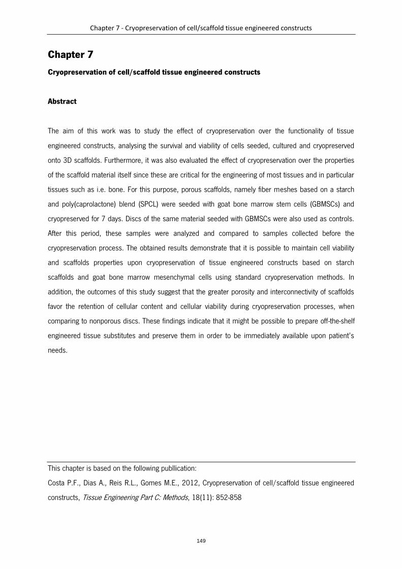
Chapter 7 - Cryopreservation of cell/scaffold tissue engineered constructs
149
Chapter 7
Cryopreservation of cell/scaffold tissue engineered constructs
Abstract
The aim of this work was to study the effect of cryopreservation over the functionality of tissue
engineered constructs, analysing the survival and viability of cells seeded, cultured and cryopreserved
onto 3D scaffolds. Furthermore, it was also evaluated the effect of cryopreservation over the properties
of the scaffold material itself since these are critical for the engineering of most tissues and in particular
tissues such as i.e. bone. For this purpose, porous scaffolds, namely fiber meshes based on a starch
and poly(caprolactone) blend (SPCL) were seeded with goat bone marrow stem cells (GBMSCs) and
cryopreserved for 7 days. Discs of the same material seeded with GBMSCs were also used as controls.
After this period, these samples were analyzed and compared to samples collected before the
cryopreservation process. The obtained results demonstrate that it is possible to maintain cell viability
and scaffolds properties upon cryopreservation of tissue engineered constructs based on starch
scaffolds and goat bone marrow mesenchymal cells using standard cryopreservation methods. In
addition, the outcomes of this study suggest that the greater porosity and interconnectivity of scaffolds
favor the retention of cellular content and cellular viability during cryopreservation processes, when
comparing to nonporous discs. These findings indicate that it might be possible to prepare off-the-shelf
engineered tissue substitutes and preserve them in order to be immediately available upon patient’s
needs.
This chapter is based on the following publlication:
Costa P.F., Dias A., Reis R.L., Gomes M.E., 2012, Cryopreservation of cell/scaffold tissue engineered
constructs, Tissue Engineering Part C: Methods, 18(11): 852-858

Chapter 7 - Cryopreservation of cell/scaffold tissue engineered constructs
150
1. Introduction
Tissue engineering is showing an increasing advancement as time goes by while cell-scaffold constructs
are expected to find a growing number of applications in the regeneration of human tissues. As the first
engineered tissue substitutes are concurrently undergoing clinical trials, and foreseeing a growing
demand for cultured cells and tissues, the tissue engineering community is becoming increasingly
worried about the challenge of providing sufficient amount of these products to the market.
One major such obstacle is related to preserving and storing “living” biomaterials. Maintaining large
stocks of living tissues will become an important issue for manufacturers and/or distributors, in order
for them to be able to ensure a steady supply of tissue substitutes. Hospitals will as well feel the need
to create tissue banks due to unpredictable demand for specific tissues in clinical settings [1, 2].
Given that simple preservation techniques, such as refrigeration or tissue culture, have drawbacks
including limited shelf-life, high cost, risk of contamination or genetic drift, cryopreservation becomes a
more viable option. This approach is based on the principle that chemical, biological and physical
processes are effectively “suspended” at cryogenic temperatures [2].
The process of developing tissue substitutes can as well require long time spans, as long as several
weeks. Starting from the isolation of autogenous cells to the in vitro expansion followed by the seeding
and culture of those cells on a scaffold and finally to implantation [3-7], there is a resulting excessively
long incapacitation of patients. In order to overcome this problem, an alternative approach, facilitating
the large-scale clinical use of engineered tissues, would be the cryopreservation of constructs, that is,
the cryopreservation of cells previously seeded and cultured onto scaffolds. This would be a way to
generate a reliable source of readily available and ready to implant engineered constructs, greatly
reducing the incapacitation time of patients.
Nevertheless, very few studies have focused on this problem [8-12]. Thus, the present study aimed at
analysing the effect of cryopreservation over cells while seeded and contained into porous and
nonporous constructs as well as the effect of cryopreservation over the morphological and mechanical
properties of the scaffold itself which are critical for the engineering of various tissues. Porosity and
mechanical properties are important features in tissue engineering scaffolding, particularly for
hard/structural tissues such as bone. Scaffolds intended to replace tissues such as bone must
preferably possess highly and fully interconnected open pore geometry, providing large surface-area
volume ratios and allowing for sufficient diffusion of nutrients and gases and removal of cellular
metabolic waste for in vitro culture, but also to enable the tissue and vascularity ingrowth upon

Chapter 7 - Cryopreservation of cell/scaffold tissue engineered constructs
151
implantation. Apart from being able to maintain the spaces required for cell in-growth and matrix
production, scaffolds for bone tissue engineering should also a priori possess enough mechanical
properties to provide structural support for neo-tissue formation upon implantation of the construct [13].
Taking all of this into consideration, we submitted cell-seeded and non seeded constructs to a standard
cryopreservation procedure for a period of 7 days and then, after a short recovery period, compared
their response, in terms of cell viability and proliferation as well as concerning the surface and
mechanical material properties, to constructs collected immediately before cryopreservation.
2. Materials and Methods
2.1 Preparation of porous scaffolds and nonporous discs
Porous scaffolds and nonporous discs were produced using a polymeric mixture of corn starch and
polycaprolactone (30/70 wt.%) designated by SPCL (Novamont, Italy). The nonporous discs were
produced by injection moulding in a Klockner Ferromatic FM-20 machine using a mould that allowed
obtaining discs with 8 mm diameter and 3 mm thickness. The porous scaffolds were produced through
a pre-established fiber bonding methodology [14, 15], briefly consisting of bonding fibers previously
obtained by melt spinning by heat and pressure, and then cut into 8 mm diameter and 3.5–4 mm thick
samples. All samples were sterilized with ethylene oxide before cell culture studies.
2.2 Cell seeding and culturing onto porous scaffolds and nonporous discs
Goat bone marrow stromal cells (GBMSC) were harvested from the iliac crest of adult goats and isolated
as described elsewhere [16] and then expanded in low-glucose Dulbecco’s modified essential medium
(DMEM; Sigma Chemical Co., St. Louis, MO, USA) supplemented with 1% antibiotic/antimycotic
(Sigma) and 10% fetal bovine serum (FBS; Sigma). When confluence was reached, cells were
trypsinized and ressuspended (at passage 4). From the obtained cell suspension, and given the
difference in surface area available for cell attachment, two different cellular concentrations were
prepared: one cell suspension to seed 5x10⁵ cells in 300 µl volumes, for the scaffolds, and the other in
order to seed 1x10⁵ cells in volumes of 200 µl onto the surface of SPCL discs. The rationale used for
the cell seeding density used in this work was based in previously performed studies [16] which showed
that a ratio of 5:1 was appropriate for being able to seed a similar amount of these cells per surface
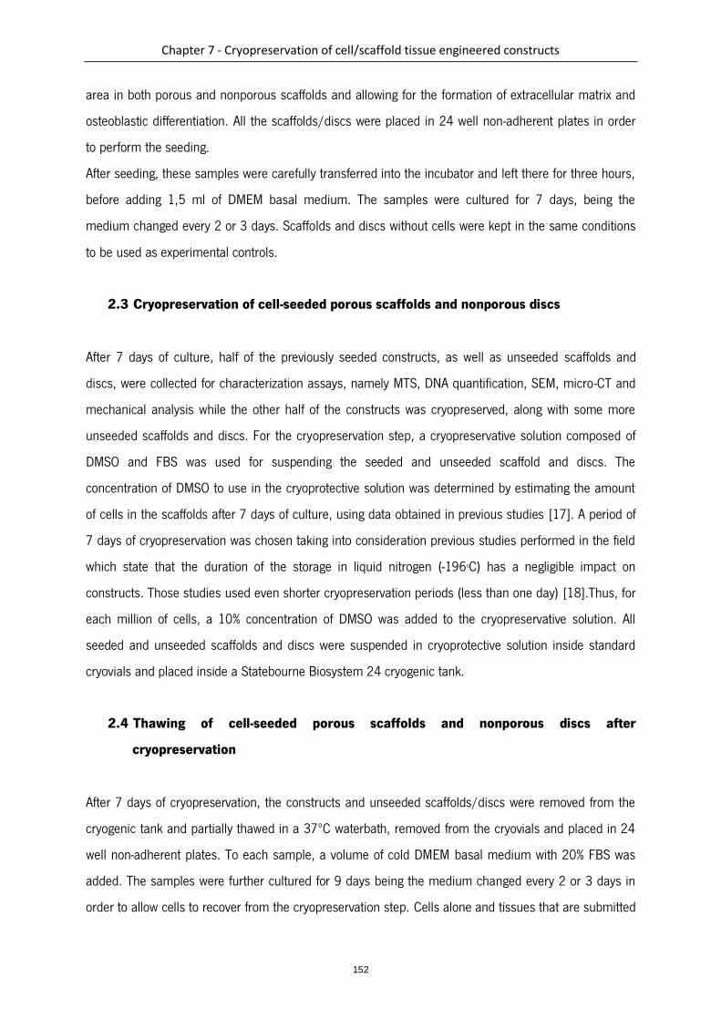
Chapter 7 - Cryopreservation of cell/scaffold tissue engineered constructs
152
area in both porous and nonporous scaffolds and allowing for the formation of extracellular matrix and
osteoblastic differentiation. All the scaffolds/discs were placed in 24 well non-adherent plates in order
to perform the seeding.
After seeding, these samples were carefully transferred into the incubator and left there for three hours,
before adding 1,5 ml of DMEM basal medium. The samples were cultured for 7 days, being the
medium changed every 2 or 3 days. Scaffolds and discs without cells were kept in the same conditions
to be used as experimental controls.
2.3 Cryopreservation of cell-seeded porous scaffolds and nonporous discs
After 7 days of culture, half of the previously seeded constructs, as well as unseeded scaffolds and
discs, were collected for characterization assays, namely MTS, DNA quantification, SEM, micro-CT and
mechanical analysis while the other half of the constructs was cryopreserved, along with some more
unseeded scaffolds and discs. For the cryopreservation step, a cryopreservative solution composed of
DMSO and FBS was used for suspending the seeded and unseeded scaffold and discs. The
concentration of DMSO to use in the cryoprotective solution was determined by estimating the amount
of cells in the scaffolds after 7 days of culture, using data obtained in previous studies [17]. A period of
7 days of cryopreservation was chosen taking into consideration previous studies performed in the field
which state that the duration of the storage in liquid nitrogen (-196oC) has a negligible impact on
constructs. Those studies used even shorter cryopreservation periods (less than one day) [18].Thus, for
each million of cells, a 10% concentration of DMSO was added to the cryopreservative solution. All
seeded and unseeded scaffolds and discs were suspended in cryoprotective solution inside standard
cryovials and placed inside a Statebourne Biosystem 24 cryogenic tank.
2.4 Thawing of cell-seeded porous scaffolds and nonporous discs after
cryopreservation
After 7 days of cryopreservation, the constructs and unseeded scaffolds/discs were removed from the
cryogenic tank and partially thawed in a 37ºC waterbath, removed from the cryovials and placed in 24
well non-adherent plates. To each sample, a volume of cold DMEM basal medium with 20% FBS was
added. The samples were further cultured for 9 days being the medium changed every 2 or 3 days in
order to allow cells to recover from the cryopreservation step. Cells alone and tissues that are submitted
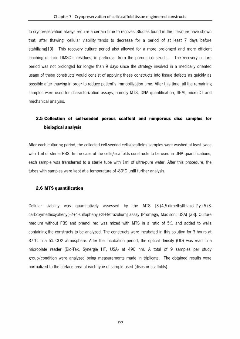
Chapter 7 - Cryopreservation of cell/scaffold tissue engineered constructs
153
to cryopreservation always require a certain time to recover. Studies found in the literature have shown
that, after thawing, cellular viability tends to decrease for a period of at least 7 days before
stabilizing[19]. This recovery culture period also allowed for a more prolonged and more efficient
leaching of toxic DMSO’s residues, in particular from the porous constructs. The recovery culture
period was not prolonged for longer than 9 days since the strategy involved in a medically oriented
usage of these constructs would consist of applying these constructs into tissue defects as quickly as
possible after thawing in order to reduce patient’s immobilization time. After this time, all the remaining
samples were used for characterization assays, namely MTS, DNA quantification, SEM, micro-CT and
mechanical analysis.
2.5 Collection of cell-seeded porous scaffold and nonporous disc samples for
biological analysis
After each culturing period, the collected cell-seeded cells/scaffolds samples were washed at least twice
with 1ml of sterile PBS. In the case of the cells/scaffolds constructs to be used in DNA quantifications,
each sample was transferred to a sterile tube with 1ml of ultra-pure water. After this procedure, the
tubes with samples were kept at a temperature of -80ºC until further analysis.
2.6 MTS quantification
Cellular viability was quantitatively assessed by the MTS [3-(4,5-dimethylthiazol-2-yl)-5-(3-
carboxymethoxyphenyl)-2-(4-sulfophenyl)-2H-tetrazolium] assay (Promega, Madison, USA) [33]. Culture
medium without FBS and phenol red was mixed with MTS in a ratio of 5:1 and added to wells
containing the constructs to be analyzed. The constructs were incubated in this solution for 3 hours at
37ºC in a 5% CO2 atmosphere. After the incubation period, the optical density (OD) was read in a
microplate reader (Bio-Tek, Synergie HT, USA) at 490 nm. A total of 9 samples per study
group/condition were analyzed being measurements made in triplicate. The obtained results were
normalized to the surface area of each type of sample used (discs or scaffolds).
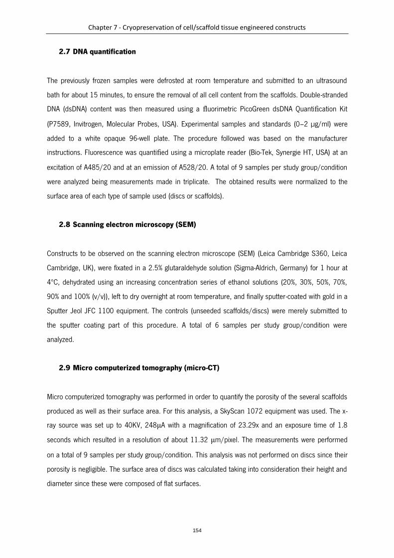
Chapter 7 - Cryopreservation of cell/scaffold tissue engineered constructs
154
2.7 DNA quantification
The previously frozen samples were defrosted at room temperature and submitted to an ultrasound
bath for about 15 minutes, to ensure the removal of all cell content from the scaffolds. Double-stranded
DNA (dsDNA) content was then measured using a fluorimetric PicoGreen dsDNA Quantification Kit
(P7589, Invitrogen, Molecular Probes, USA). Experimental samples and standards (0–2 µg/ml) were
added to a white opaque 96-well plate. The procedure followed was based on the manufacturer
instructions. Fluorescence was quantified using a microplate reader (Bio-Tek, Synergie HT, USA) at an
excitation of A485/20 and at an emission of A528/20. A total of 9 samples per study group/condition
were analyzed being measurements made in triplicate. The obtained results were normalized to the
surface area of each type of sample used (discs or scaffolds).
2.8 Scanning electron microscopy (SEM)
Constructs to be observed on the scanning electron microscope (SEM) (Leica Cambridge S360, Leica
Cambridge, UK), were fixated in a 2.5% glutaraldehyde solution (Sigma-Aldrich, Germany) for 1 hour at
4ºC, dehydrated using an increasing concentration series of ethanol solutions (20%, 30%, 50%, 70%,
90% and 100% (v/v)), left to dry overnight at room temperature, and finally sputter-coated with gold in a
Sputter Jeol JFC 1100 equipment. The controls (unseeded scaffolds/discs) were merely submitted to
the sputter coating part of this procedure. A total of 6 samples per study group/condition were
analyzed.
2.9 Micro computerized tomography (micro-CT)
Micro computerized tomography was performed in order to quantify the porosity of the several scaffolds
produced as well as their surface area. For this analysis, a SkyScan 1072 equipment was used. The x-
ray source was set up to 40KV, 248μA with a magnification of 23.29x and an exposure time of 1.8
seconds which resulted in a resolution of about 11.32 μm/pixel. The measurements were performed
on a total of 9 samples per study group/condition. This analysis was not performed on discs since their
porosity is negligible. The surface area of discs was calculated taking into consideration their height and
diameter since these were composed of flat surfaces.

Chapter 7 - Cryopreservation of cell/scaffold tissue engineered constructs
155
2.10 Atomic Force Microscopy (AFM)
The roughness of the samples (SPCL discs) surfaces was measured by AFM. The analysis was
performed on 3 samples per study group/condition on at least three spots per sample using tapping
mode in a multimode scanning probe microscope (Veeco, USA) connected to a NanoScope III (Veeco,
USA) with non-contacting silicon nanoprobes (ca. 300 kHz, setpoint 2–3 V) (Nanosensors, Switzerland).
All images were fitted to a plane using the 1st degree flatten procedure included in NanoScope software
version 4.43r8.
2.11 Mechanical analysis
Scaffolds and discs were submitted to compression tests before and after cryopreservation for
determining their compressive modulus, using a Universal tensile testing machine (Instron
4505 Universal Machine). The tests were performed under compression loading using a crosshead
speed of 2 mm/min until 60% strain was reached. The compressive modulus was determined in the
most linear region of the stress–strain curve using the secant method. A total of 10 samples per study
group/condition were used for this analysis.
2.12 Statistics
DNA and MTS assays results are presented as means standard deviation. Statistical evaluation was
performed using two-tailed paired Student t tests, to assess the statistical differences between groups at
different time points. Statistical significance was defined as p < 0.05 for a 95% confidence interval.
3. Results
3.1 Viability, cellular content and morphology of GBMSCs on porous scaffolds and
nonporous discs before and after cryopreservation
GBMSCs were successfully seeded and cultured under basal culture conditions on the porous scaffolds
and nonporous discs for 7 days. Constructs were cryopreserved under standard conditions for 7 days,
thawed and then cultured for a further period of 9 days to allow for full cellular recovery and efficient
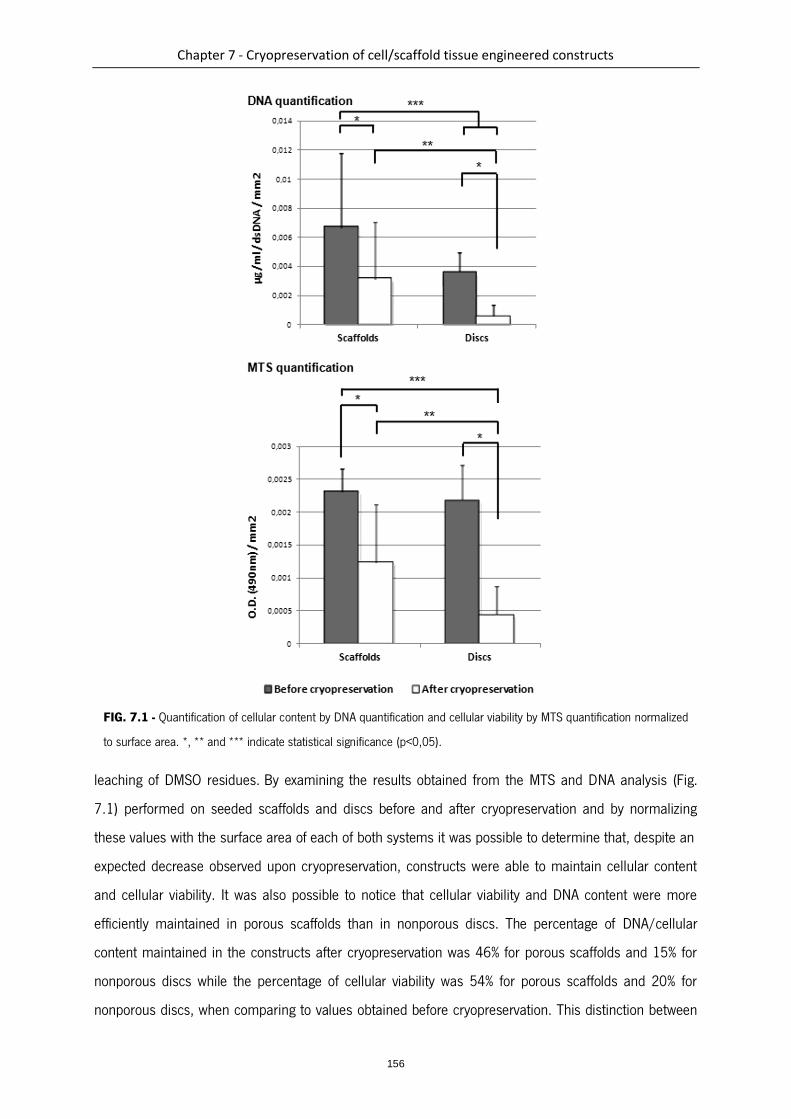
Chapter 7 - Cryopreservation of cell/scaffold tissue engineered constructs
156
FIG. 7.1 - Quantification of cellular content by DNA quantification and cellular viability by MTS quantification normalized
to surface area. *, ** and *** indicate statistical significance (p<0,05).
leaching of DMSO residues. By examining the results obtained from the MTS and DNA analysis (Fig.
7.1) performed on seeded scaffolds and discs before and after cryopreservation and by normalizing
these values with the surface area of each of both systems it was possible to determine that, despite an
expected decrease observed upon cryopreservation, constructs were able to maintain cellular content
and cellular viability. It was also possible to notice that cellular viability and DNA content were more
efficiently maintained in porous scaffolds than in nonporous discs. The percentage of DNA/cellular
content maintained in the constructs after cryopreservation was 46% for porous scaffolds and 15% for
nonporous discs while the percentage of cellular viability was 54% for porous scaffolds and 20% for
nonporous discs, when comparing to values obtained before cryopreservation. This distinction between
Chapter 7 - Cryopreservation of cell/scaffold tissue engineered constructs
157
the behavior of cells in porous scaffolds and discs was particularly visible in the MTS data which
showed an evolution from statistically similar cellular viability between both groups before
cryopreservation to a statistically and significantly higher cellular viability of cells in porous scaffolds
after cryopreservation. These results corroborated our expectations that cells seeded in porous scaffolds
would be better preserved given that the scaffold´s pores would retain the cryoprotectant more
efficiently. As well, and also importantly, these results showed that, along with a prolonged recovery
time for cellular viability stabilization, there was an effective removal of the cryoprotectant from the
porous scaffold after cryopreservation. Cryoprotectants, in particular the one we used (DMSO), are
known to be highly toxic for cells and, for this reason, it would be crucial not only to maintain the
cryoprotectant inside the scaffold during cryopreservation but also to make sure it would be efficiently
removed after cryopreservation. For the efficiency of the cryoprotectant’s removal contributed the
scaffold’s specific porosity and architecture.
Through the SEM analysis (Fig. 7.2) it was possible to observe that the cellular morphology was not
affected by the cryopreservation process and that cells remained well attached to the material’s
surfaces after thawing.
FIG. 7.2 - SEM micrographs of SPCL discs and scaffolds before and after cryopreservation at magnification 1000x.
GBMC-seeded SPCL discs before A) and after B) cryopreservation (magnification 1000x); GBMC-seeded SPCL scaffolds
before C) and after D) cryopreservation (magnification 200x)

Chapter 7 - Cryopreservation of cell/scaffold tissue engineered constructs
158
3.2 Morphology, surface topography and architecture of porous scaffolds and
nonporous discs before and after cryopreservation
By comparing the SEM micrographs (Fig. 7.2) before and after cryopreservation it was possible to
observe that the cryopreservation process did not change the material’s surface morphology. After
cryopreservation, the surface of the fibers of porous scaffolds as well as the surface of the nonporous
discs showed the same smooth topography as before cryopreservation. This was more accurately
confirmed by performing an AFM analysis (Fig. 7.3) on the surface of nonporous discs which revealed
FIG. 7.3 - AFM images of SPCL discs before A) and after B) cryopreservation and their average roughnesses C). Values of
average roughness before and after cryopreservation were not significantly different (p>0,05).

Chapter 7 - Cryopreservation of cell/scaffold tissue engineered constructs
159
no significant difference between sample’s roughness before and after cryopreservation. It was not
possible to perform the same AFM analysis over the porous scaffolds given the very irregular fibrous
architecture. In the same way, a micro-ct analysis and reconstruction was performed on the porous
scaffolds showing that the cryopreservation process did not alter the general architecture of scaffolds as
well as its porosity as show in the performed micro-ct 3D reconstructions (Fig. 7.4A and B) and porosity
quantitative analysis results (Fig. 7.4C).
FIG. 7.4 - Micro-CT analysis of fiber bonded scaffolds before A) and after B) cryopreservation. No significant difference
was found in terms of scaffold morphology. A quantitative analysis was also performed in order to compare the total
porosity of scaffolds before and after cryopreservation C). The values of average porosity before and after cryopreservation
were not significantly different (p>0,05).

Chapter 7 - Cryopreservation of cell/scaffold tissue engineered constructs
160
3.3 Mechanical properties of porous scaffolds and nonporous discs before and after
cryopreservation
Compression mechanical tests were performed on cryopreserved and non cryopreserved porous
scaffolds and nonporous discs. The results showed that the cryopreservation process did not alter the
mechanical compressive properties of scaffolds and discs since there was no significant difference
found when comparing the values for young´s modulus before and after cryopreservation (Table 7.1).
4. Discussion
In this work we were able to show that it is possible to maintain cellular content and cellular viability into
cell-seeded constructs in standard cryopreservation conditions as shown by the MTS, DNA and SEM
results. Furthermore, we were able to show that the porosity and pore interconnectivity found in porous
scaffolds may in fact beneficially influence the viability and retention of cells in constructs exposed to
cryopreservation processes. This observation may be explained by a possible retaining and protective
effect exerted by the scaffold over the cells contained inside the scaffold’s pores against the intrinsic
damaging effects of cryopreservation.
As for the morphology of scaffolds and discs, we were able to assess that it was not damaged or altered
by the cryopreservation process both at a macroarchitectural level as also in terms of superficial
topography. This is an important observation since scaffold’s architecture and surface morphology are
known to greatly influence the efficiency of cell adhesion and subsequent proliferation over material’s
surfaces.
Starch–polycaprolactone fiber mesh scaffolds have been extensively studied, demonstrating very
promising results, both in vitro and in vivo, for applications in the tissue engineering field [16, 17, 20].
TABLE 7.1 - Comparative compression mechanical analysis on scaffolds and discs before and after cryopreservation.
Values of average Young’s modules before and after cryopreservation were not significantly different (p>0,05).

Chapter 7 - Cryopreservation of cell/scaffold tissue engineered constructs
161
We were also able to assess that the cryopreservation process did not alter the mechanical compressive
properties of SPCL based scaffolds and discs since there was no significant difference found when
comparing the values for young´s modulus before and after cryopreservation. This means that it would
be possible to accurately define construct’s mechanical properties prior to cryopreservation aiming at
specific tissue applications (in this case, given the mechanical properties of the studied scaffolds,
mostly bone and cartilage) without having any detrimental effect caused by the cryopreservation
process. The same principle applies to the architecture and surface topography of scaffolds which, as
shown by the performed SEM, AFM and micro-CT analysis, are also not affected by the cryopreservation
process.
Overall, the obtained results show that it is possible to maintain viable cells and scaffolds properties
upon cryopreservation of tissue engineered constructs based on SPCL scaffolds and goat bone marrow
mesenchymal cells using standard cryopreservation methods. Also, this study suggests that the
architecture found in porous scaffolds favors the retention and viability of construct’s cellular content
during cryopreservation processes, when compared to nonporous structures. Finally, these findings
indicate that it may be possible to prepare off-the-shelf engineered tissue substitutes and preserve them
in order to be immediately available upon patient’s need.
5. Acknowledgments
This work was partially supported by the European Network of Excellence EXPERTISSUES (NMP3-CT-
2004-500283). It is also acknowledged the Portuguese Foundation for Science and Technology for the
PhD grant of Pedro Costa (SFRH/BD/62452/2009) and the research grant of Ana Dias in the scope of
the research project VivoTissue (PTDC/CVT/67677/2006).
6. References
1. Hirose, M., et al., Osteogenic potential of cryopreserved human bone marrow-derived
mesenchymal cells after thawing in culture. Mater Sci Eng C, 2004. 24(3): p. 355-359.
2. Karlsson, J.O. and M. Toner, Long-term storage of tissues by cryopreservation: critical issues.
Biomaterials, 1996. 17(3): p. 243-56.
3. Fleming, J.E., Jr., C.N. Cornell, and G.F. Muschler, Bone cells and matrices in orthopedic tissue
engineering. Orthop Clin North Am, 2000. 31(3): p. 357-74.

Chapter 7 - Cryopreservation of cell/scaffold tissue engineered constructs
162
4. Hutmacher, D.W., Scaffolds in tissue engineering bone and cartilage. Biomaterials, 2000.
21(24): p. 2529-43.
5. Kim, B.S. and D.J. Mooney, Development of biocompatible synthetic extracellular matrices for
tissue engineering. Trends Biotechnol, 1998. 16(5): p. 224-30.
6. Perka, C., et al., Tissue engineered cartilage repair using cryopreserved and noncryopreserved
chondrocytes. Clin Orthop Relat Res, 2000(378): p. 245-54.
7. Vacanti, C.A. and L.J. Bonassar, An overview of tissue engineered bone. Clin Orthop Relat Res,
1999(367 Suppl): p. S375-81.
8. Miyoshi, H., et al., Cryopreservation of Fibroblasts Immobilized Within a Porous Scaffold: Effects
of Preculture and Collagen Coating of Scaffold on Performance of Three-Dimensional Cryopreservation.
Artificial Organs, 2010. 34(7): p. 609-614.
9. Yin, H., et al., Vitreous cryopreservation of tissue engineered bone composed of bone marrow
mesenchymal stem cells and partially demineralized bone matrix. Cryobiology, 2009. 59(2): p. 180-
187.
10. Rupf, T., et al., Cryopreservation of Organotypical Cultures Based on 3D Scaffolds. Cryoletters,
2010. 31(2): p. 157-168.
11. Bernemann, I., M. Kuberka, and B. Glasmacher, 71. Adapted freezing and thawing procedures
to improve the cryopreservation of cell seeded scaffolds. Cryobiology, 2006. 53(3): p. 397-398.
12. Kofron, M.D., et al., Cryopreservation of tissue engineered constructs for bone. Journal of
Orthopaedic Research, 2003. 21(6): p. 1005-1010.
13. Salgado, A.J., O.P. Coutinho, and R.L. Reis, Bone Tissue Engineering: State of the Art and
Future Trends. Macromolecular Bioscience, 2004. 4(8): p. 743-765.
14. Mendes, S.C., et al., Evaluation of two biodegradable polymeric systems as substrates for bone
tissue engineering. Tissue Eng, 2003. 9 Suppl 1: p. S91-101.
15. Gomes, M.E., et al., Influence of the porosity of starch-based fiber mesh scaffolds on the
proliferation and osteogenic differentiation of bone marrow stromal cells cultured in a flow perfusion
bioreactor. Tissue Eng, 2006. 12(4): p. 801-809.
16. Rodrigues, M.T., et al., Tissue-engineered constructs based on SPCL scaffolds cultured with
goat marrow cells: functionality in femoral defects. Journal of Tissue Engineering and Regenerative
Medicine, 2011. 5(1): p. 41-49.
Chapter 7 - Cryopreservation of cell/scaffold tissue engineered constructs
163
17. Gomes, M.E., et al., Effect of flow perfusion on the osteogenic differentiation of bone marrow
stromal cells cultured on starch-based three-dimensional scaffolds. J Biomed Mater Res A, 2003.
67(1): p. 87-95.
18. Wen, F., et al., Vitreous cryopreservation of nanofibrous tissue-engineered constructs generated
using mesenchymal stromal cells. Tissue Engineering - Part C: Methods, 2009. 15(1): p. 105-114.
19. Lübke, C., et al., Cryopreservation of Artificial Cartilage: Viability and Functional Examination
after Thawing. Cells Tissues Organs, 2001. 169(4): p. 368-376.
20. Tuzlakoglu, K., et al., Nano- and micro-fiber combined scaffolds: A new architecture for bone
tissue engineering. Journal of Materials Science: Materials in Medicine, 2005. 16(12): p. 1099-1104.


165
Section III
General conclusions

Chapter 8 - General conclusions and future work
167
Chapter 8
General conclusions and future work
1. Conclusions
Over the last two decades, tissue engineering has shown great promise in the regeneration of human
tissues. Despite the clear evidences that tissue engineering can be applied to the replacement and
regeneration of damaged tissues, its translation from the lab to clinical widespread application has
experienced important obstacles. This can be mostly explained by the complexity of the majority of the
human tissues, that requires labour-intensive procedures to achieve functional tissue-like substitutes
and to the inability of tissue engineering companies to shift from these methodologies to
industrial/mass production processes. Automation is therefore seen as an urgently required means for
enabling this transition. Several automated tools and strategies have been adopted by tissue
engineering over time, among them additive manufacturing and bioreactor technologies, which were the
focus of the work presented in this thesis.
Therefore, the work described in this thesis, namely under chapters 3, 4 and 5 reports to the use of
the additive manufacturing technology to develop advanced cell/tissue culture systems composed of
scaffolds contained into specifically designed bioreactor chambers. In the work described in chapter 4,
and by resorting to medical imaging technologies, the first application of this concept allowed to
additively manufacture bone tissue replicas which were simultaneously and concomitantly
manufactured with enclosing culture chambers. As a proof of concept, this technology was employed in
the design and fabrication of a sheep-tibia scaffold around which a bioreactor chamber of similar shape
was simultaneously constructed. The morphology of the resulting device was investigated by micro-
computed tomography and scanning electron microscopy confirming the porous architecture of the
internal scaffold as opposed to the non-porous nature of the bioreactor chamber. Additionally, this
study demonstrated that both the shape, as well as the inner architecture of the device can significantly
impact the perfusion of fluid within the scaffold. Indeed, fluid flow modelling revealed that this was of
significant importance for controlling the fluid flow pattern within the scaffold and the device, avoiding
the formation of stagnant regions detrimental for in vitro tissue development. The design of these
culture chambers was optimized by resorting to fluid flow simulation models which allowed to predict
the behavior of fluids resulting from the integration into a perfusion culture system. As a result, an
optimal chamber design was achieved and multiple copies were additively manufactured for further
Chapter 8 - General conclusions and future work
168
testing. The additive manufacturing fabrication of each of the culture devices utilized was completed
within 45 minutes, being the inner scaffold further post-treated with sodium hydroxide for increased
hydrophilicity and the outer chamber post-treated with an ABS solution for increased watertightness.
Finally, to demonstrate the feasibility of the proposed approach/construct, osteoblast cells were seeded
into the replica scaffold and cultured over a period of 6 weeks under flow perfusion. The perfusion
culture was performed bidirectionally by means of a standard syring pump. After culture, and due to the
proposed design of the culture chambers, the cultured scaffolds could be easily collected from the
interior of the device by simply cutting the device’s walls with sterile scissors and tweezers. The
analysis of the extracted constructs showed that the cell seeding was homogeneous throughout the
whole scaffolds despite their large dimensions. Furthermore, cells found throughout the full thickness of
those same large constructs were viable during the full duration of the 6 week study. This work
demonstrated a novel application for additive manufacturing in the development of scaffolds and
bioreactors which would contribute to the advancement of customized tissue engineering strategies for
a wide range of applications. Unlike the large majority of bioreactors utilized in tissue engineering,
which typically only enable culturing small cylindrical constructs, the device herein developed can be
easily adapted on the fly to any construct’s shape and size. Furthermore, this technology allows
developing bioreactors that can be specifically designed to optimize aspects such as medium volumes
or medium fluid flow patterns which in turn can modulate cellular density, survival and development.
This high degree of versatility enabled by the utilization of additive manufacturing also allows to freely
design the inner scaffold itself, independently. Furthermore, the enclosure (bioreactor chamber) and the
inner scaffold can be built from a wide array of materiais which are currently available as well as many
more materials which can be developed/optimized in the future. Apart from the melt-based FDM
additive manufacturing employed in the work described in this thesis, many other additive
manufacturing technologies are already available, which are capable of utilizing materials as demanding
as i.e. metals or ceramics, hence increasing even more the range of materials to use in the fabrication
of tissue engineering bioreactors and scaffolds, meeting broader requirements. Furthermore, due to
the enclosed nature of the developed bioreactor, it becomes now safer to culture tissue engineered
constructs as well as to transport them to various environments (such as i.e. surgery rooms) since the
exposure to external contaminants can be greatly reduced by the device’s outer walls. To our
knowledge, this new concept employs additive manufacturing in a way that has never been used before.
Furthermore, and most importantly, this new concept enables the development and fabrication of highly
tailored culture systems which are as well inexpensive, easy to build, easy to use and highly versatile.

Chapter 8 - General conclusions and future work
169
In order to become commercially viable, tissue engineering must not only become an automated
process but must be as well able to generate large amounts of tissue substitutes in a scenario of
widespread utilization of tissue engineered products. High throughput screening is a methodology which
greatly relies on automation for producing large amounts of samples which can afterwards be tested
and analyzed through equally automated technologies. In a tissue engineering context, high throughput
screening can be used for testing and optimizing the combination of tissue engineered constructs
possessing variable properties with variable culture conditions being therefore an extreme case of mass
production of tissue engineered constructs samples. In this sense, additive manufacturing was again
utilized in chapter 5 of this thesis to optimize and produce an up-scalable perfusion-based culture
device enabling to simultaneously seed and culture large amounts of scaffolds in its interior. The
developed device was also designed to enable surface modification of scaffolds by perfusion with
aqueous solutions. As a proof-of-concept, the developed device was utilized to deposit a calcium
phosphate osteoinductive coating over the surface of scaffolds which were then seeded and cultured
with osteoblast for a period of 4 weeks. The technique utilized allowed the simultaneous in vitro culture
of a total of 96 scaffolds under controlled bi-directional perfusion. The analysis of the resulting
constructs demonstrated that the developed device was able to promote homogeneous cell adhesion
over the surface of scaffolds as well as cellular proliferation along the culture period as shown by DNA
quantification assays. The presence of the calcium phosphate coating showed to further improve these
results when comparing to non-coated scaffolds seeded and cultured under the same conditions. The
methodology developed in this work exemplifies the applicability of additive manufacturing as a tool for
achieving further automation of HTS in the field of biomedical science and biotechnology as well as the
potential to enable mass production of large ammounts of tissue engineered constructs. The most
important feature of the developed device is that it allows to easily add a third dimension to HTS, unlike
the majority of currently existing HTS devices which are only capable of performing 2D cultures. In this
way, more realistic screening can be achieved since it is well known that cells behave and develop
differently depending on wether they are in a 3D or a 2D environment. By employing additive
manufacturing to simultaneously build unlimited amounts of 3D culture environments, HTS is able to
become more realistic and therefore more closely mimic events happening in natural living tissues.
Furthermore, given that the developed platform is 3D and not 2D, it becomes possible to upscale and
highly optimize the number of tests to device size ratio allowing to develop systems with large number
of 3D test chambers contained into very small devices.

Chapter 8 - General conclusions and future work
170
Additive manufacturing can as well be combined with other technologies to produce constructs with
greater complexity. In the work described in chapter 6 we have been able to combine additively
manufactured scaffolds with a melt electrospinning technology for producing single biphasic scaffolds
for the regeneration of the bone-periodontal ligament-cementum interface. The additively manufactured
part of the scaffold was further treated by adding an osteoinductive coating in order to promote the
formation of bone tissue into that section of the scaffold upon implantation. The electrospun part of the
scaffold was attached to the additively manufactured scaffold by means of a melt and press-fitting
methodology. The porous additively manufactured part of the scaffold was then seeded with osteoblasts
in order to generate a construct similar to the bone found anchoring teeth. On the other hand, the
electrospun part of the scaffold served as a support for the deposition of periodontal ligament cell
sheets which would later be responsible for the attachment of the scaffold’s bone construct to a dentin
block intended to simulate the surface of teeth. The biphasic construct was subcutaneously implanted
in rats in order to assess the efficacy of this tissue engineered guided tissue regeneration strategy. The
deposition of periodontal ligament cell sheets resulted in a greater degree of attachment at the bone-
tooth interface after 8 weeks of in vivo implantation. The biomimetic coating was as well responsible for
increasing the quality of the bone tissue formed at the additively manufactured part of the scaffold by
accelerating its formation in vivo as well as during the preceding in vitro culture stage. In short, the
biphasic scaffold design studied in this work was able to display suitable properties for periodontal
regeneration based on faultless tissue integration of both compartments, high levels of vascularization
and tissue orientation in both the bone and most importantly periodontal compartment, allowing for
significant fiber attachment formation. Unlike many other suggested treatments for defects resulting
from severe cases of periodontitis, the scaffold herein developed resulted as a single all -in-one solution
since it was able to simultaneously fulfill three main principles, namely wound stabilization due to its
mechanical properties, space maintenance due to the creation of integrated cavities and selective cell
repopulation due to its biphasic nature. The ability of the developed scaffold to generate organized and
oriented tissues is also an important feature which is rarely achieved in such a simple and
straightforward way. Furthermore, given the ability of the developed device to serve as a template for
the regeneration of the studied interface, it might also be be adapted to other tissue interfaces such as,
for example, osteochondral or bone-ligament interfaces.
Finally, the mass production and usage of tissue engineering and regenerative medicine products would
also be much benefited if an efficient way to store such constructs could be found and optimized. To
that end, in the work described in chapter 7, we have evaluated a simple methodology to store tissue

Chapter 8 - General conclusions and future work
171
engineered constructs by means of cryopreservation which is know to enable the suspension of
chemical, biological and physical processes for long periods of time. This study consisted of a
comparative study in which both porous scaffolds and non-porous discs were seeded with goat bone
marrow stem cells and cryopreserved for 7 days. By comparing to non cryopreserved constructs it was
possible to evaluate the effect of cryopreservation. The obtained results showed that it is possible to
maintain viable cells and scaffolds properties upon cryopreservation of tissue engineered constructs
based on SPCL scaffolds and goat bone marrow mesenchymal cells using standard cryopreservation
methods. Futhermore, this study suggested that the architecture found in porous scaffolds may be able
to favor the retention and viability of construct’s cellular content during cryopreservation processes,
when comparing to nonporous structures. Given that currently the process of developing tissue
substitutes still requires long time spans (as long as several weeks) and that, if applied, such strategy
would require excessively long incapacitation of patients, the concept of cryopreserved off-the-shelf
tissue engineered products would definitely make a significant difference in patient’s quality of life. Such
products would also be of substantive value in situations of high demand (i.e. large scale disasters) to
which currently there are no effective solutions. Finally, the device and method described in the patent
in annex 1, was thought at solving a major obstacle in tissue engineering, which is vascularization. Very
few tissues are able to survive without integrating a proper vascular network providing nutrition which
can as well withstand a certain level of biomechanical constraints. The cellular construct achievable
through the described method would allow to more quickly generate blood vessel substitutes since they
would a priori possess such properties given their integrated electrospun mesh. Apart from the
mechanical properties, and very importantly, this mesh enables as well an efficient way of segregating
and placing each of the cellular types forming blood vessels (fibroblasts, endothelial and smooth muscle
cells) into their respective locations in the vessel, hence more closely mimicking the natural structure of
blood vessels.
As a final remark, we believe that the work developed in the scope of this PhD thesis has contributed to
further unveil the high potential of additive manufacturing in tissue engineering applications, in
particular when combined with other technologies such as electrospinning, biomimetic surface
treatments and bioreactor technologies. Such combined technologies will in the future enable the
application of substantial degrees of automation into the fabrication of tissue engineering products
which will in turn become more accessible and more commonly considered as practical and viable
solutions for tissue regeneration. Furthermore, and relating to the work developed in the final part of
this thesis, we believe that it may become possible in the future to prepare off-the-shelf engineered

Chapter 8 - General conclusions and future work
172
tissue substitutes and preserve them in order to be immediately available upon patient’s need.
Therefore, the concept of mass produced and pacient-specifc replacement body parts is becoming
closer to reality, however much more technological development and process optimization is needed for
it to become common practise.
2. Future work
The work developed in the scope of this PhD provides strong evidence of the enormous potential
residing in the automation of tissue engineering and simultaneously opens the way to many other
possible approaches that can be further explored in future.
For example, related to the work described in chapters 3 to 5 of this thesis, more complex culture
devices could be developed in the future in order to enable the simultaneous culture of large amounts
of tissue constructs either for mass production of tissue substitutes or for high throughput screening
purposes. Given that the developed devices were duly validated, a scaleup of the devices and/or of the
device systems would be the first logical step. In this way, devices able to seed and culture large
ammounts of tissue substitutes under standardized, traceable, cost-effective, safe and regulatory-
compliant conditions would facilitate the realization of a scenario of widespread adoption of tissue
engineering-based therapies in which large amounts of tissue substitutes would need to be
simultaneously produced in order to fulfil demands.
In a high throughput screening perspective, as shown in chapter 5 of this thesis, the developed device
and its design process could as well be improved. The success of a high throughput screening
technology resides mainly on its ability to simultaneously expose large amounts of samples to varying
ranges of factors in short periods of time and space and therefore high throughput screening tends to
test large batches of samples simultaneously into one single device. As the number of samples and
variable factors to be tested in a single device increase so does the complexity of the utilized device
hence, given that the design of the developed device is performed manually, the increase in device
complexity would therefore demand for greater human intervention. Automation of the design process
might provide the solution for that issue. In a methodology called parametric design, shapes and
objects can be numerically designed by simple introduction of a reduced number of design parameters.
By applying parametric design, devices would be automatically designed with reduced human
intervention. Given that the developed devices are built by means of an equally automated process of
additive manufacturing, a fully automated process could be implemented in which the operator would
insert design parameters (such as number, size, shape of scaffolds) and as a result a fully functional

Chapter 8 - General conclusions and future work
173
HTS device would be effortlessly fabricated. Furthermore, the same parametrical methodology could as
well be applied to the generation of varying chamber and fluid network designs resulting in the
generation of multiple culture conditions into individual culture chambers of one same device.
The device and methodology decribed in chapter 4 shows as well a great potential for improvement and
optimization. Being the aim of that work to address tailor-made tissue engineering, a wide range of new
applications can be envisioned. The developed strategy can be virtually applied to the regeneration of
any kind of tissue and organ. Given the high versatility of additive manufacturing, the inner and outer
architectures of scaffolds and constructs can be made more complex and optimized in order to closely
resemble the ones found in native tissues.
The applicability to such wide range of structures would require as well the utilization of a wider range
of materials which would be able to more closely mimick the distinct properties of various tissues. In
the same way, the combination of multiple materials into the regeneration of tissues would allow for the
generation of complex structures composed of multiple types of tissues. A probable first combination of
materials would involve the merger of solid materials (such as the ones already used) with more soft
and flexible materials such as hydrogels or ready-made structures such as the one described in annex 1
which would enable the combination of soft structures such as blood vessels and nervous networks into
more solid structures replicating tissues such as bone. Furthermore, the functionality of materials
composing additively manufactured tailor-made scaffolds could as well be enhanced by performing
surface treatments such as the ones performed in the devices described in chapters 5 and 6.
The biphasic scaffold utilized in chapter 6 is in fact a good example of the regeneration of multiple kinds
of tissues into one same device by combination of materials with diverging properties. Given its ability to
simultaneously regenerate bone tissue and periodontal ligament into one single construct both in vitro
and in vivo (in a subcutaneous rat model), further in vivo studies should be performed onto larger
animal models and into more realistic jaw defects. The in vitro generation of such constructs could as
well be facilitated or even improved by utilizing dynamic cell culture in a strategy similar to the ones
described in chapters 3 to 5. Such culture devices could be designed to segregate the different cell
types into their specific scaffold regions and in a way allowing to apply the intended guided tissue
regeneration methodology prior to implantation.
Finally, regarding the cryopreservation of tissue engineered constructs studied in chapter 7 of this
thesis, although it has been shown to be possible, its efficiency should be further improved in order to
become a more viable storage option. Other cryopreservation methodologies and cryoprotectants
should as well be studied and compared in a systematic way in order to assess the best methodology or

Chapter 8 - General conclusions and future work
174
combination of methodologies. Multiple cell sources should also be tested in this same way in order to
assess if cell survival varies according to cellular origin/type.
Annex 1 - Single-step method and device for the generation of stratified tubular tissue substitutes
175
Annex 1
Single-step method and device for the generation of stratified tubular tissue substitutes
Abstract
Device and method for manufacturing stratified tubular tissue. The device comprises a lower
rectangular part (3) over which a porous membrane (4) is centrally placed, a malleable part with a
closed (5) or open (6) configuration, provide with tubular structures (9) and defining at least two
contiguous cavities in its lower surface, placed over the lower rectangular part (3) and over specific
zones of the porous membrane (4), and a third part (7) with screws (8), which compresses the
malleable part (5 or 6) and particularly against the porous membrane (4).
This annex is based on the following publlication:
Costa P.F., Martins A., Vaquette C., Neves N.M., Gomes M.E., Hutmacher D.W., Reis R.L., Single-step
method and device for the generation of stratified tubular tissue substitutes, World Patent Application
WO2013/085404 A1.
Annex 1 - Single-step method and device for the generation of stratified tubular tissue substitutes
176
1. Object of the invention
The present invention is related to the manufacturing of stratified and tubular tissue substitutes for the
replacement/regeneration of composite animal or human tissues, which may have been previously
damaged by means of disease or trauma. The present invention describes a device which enables the
simultaneous culture of multiple and different cellular types into porous membranes, as well as the
method to manufacture stratified tubular tissue substitutes from those porous membranes cultured with
multiple different cellular types.
2. Background
Live tissues are assemblies of cells arranged in a specific organized fashion. In some cases, cells are all
structurally and functionally alike, forming simple tissues (e.g. cartilage, epithelial and adipose tissues).
However, most tissues in the human body contain a mixture of cells with distinctive functions, which
may be termed compound tissues (e.g. bone, skin, nervous and vascular tissues. Cells that form
tissues can be divided into parenchymal cells, which maintain tissues, and support cells, which provide
the structural scaffolding of a tissue. Support cells comprise a set of highly developed cell types with
complex metabolic functions and produce an extracellular matrix (ECM) , which largely defines the
physical characteristics of a tissue. The support cells together with ECM are organized in an elaborate
and hierarchical order to achieve multi-scale functions and to mutually regulate the cellular activity by
soluble bioactive molecules, cell-cell direct contact, or cell-ECM interaction. This elaborate structure also
provides individual cells with different microenvironments, where cells experience specific cues and
show corresponding responses towards tissue function.
Tissue Engineering has been recognized, for some time, as a promising alternative to the use of
autografts or allografts for tissue reconstruction and regeneration. This approach utilizes cells,
biomaterial scaffolds and signaling molecules for the repair of diseased or damaged tissues. Despite the
great progress in this field, development of clinically relevant size tissues with complex architecture
remains a great challenge. This is mostly due to limitations of nutrient and oxygen delivery to cells and
limited availability of scaffolds, which can mimic the complex live tissue architecture. Biomaterial
scaffolds are designed to support cell and tissue growth, aiming at a macroscopic level to be
compatible with the mechanical loading of the surrounding organs and tissues but without the need to

Annex 1 - Single-step method and device for the generation of stratified tubular tissue substitutes
177
recreate the complexity and nanoscale detail observed in tissues and organs at the extracellular level. In
a Tissue Engineering and Regenerative Medicine approach, the development of a synthetic ECM is a
critical issue, since we need to learn from nature how to engineer biomaterials that will help in
recapitulating the early events of morphogenesis that lead to the formation of the hierarchical
organization of the ECM and drive the cells to build fully functional adult tissues. To maintain the proper
cell phenotype in 3D tissue engineering one needs to achieve biomimetic design to replicate the ECM,
seeding/infiltration of cells into a biomaterial scaffold and culturing the seeded scaffold with adequate
nutrient supply.
The in vivo microenvironment for each cell type varies from tissue to tissue and from site to site, and
this variation provides and conveys specific cues to cells for specific functions. Besides the recognized
complex hierarchical organization, cells in tissues constantly experience mechanical stimuli. Therefore,
culturing cells in the appropriate biochemical environment and in the presence of mechanical stimuli
will provide a more realistic extracellular microenvironment and, consequently, will improve cell -cell and
cell-matrix interactions. Various developed bioreactor systems introduce convective flow of the medium
to perfuse in vitro-grown 3D tissue constructs, e.g. spinner flasks, rotary vessels or perfusion flow
systems. The use of these bioreactor systems can allow a homogeneous cell seeding of the biomaterial
scaffold, a good nutrient distribution through the scaffold, and an efficient removal of metabolites at the
cellular and sub-cellular levels. Consequently, there is a huge scientific interest in obtaining the
appropriate mechanical environments to improve the quality and functionality of the in vitro-generated
hybrid constructs.
3. Description of the invention
The present invention describes a device, which enables the simultaneous culture of multiple and
different cellular types into porous membranes as well as the method to fabricate stratified tubular
tissue substitutes from those porous membranes cultured with multiple different cellular types.
The device herein described allows to separately seeding and culture multiple and different cell types
into separate areas of one same porous membrane.

Annex 1 - Single-step method and device for the generation of stratified tubular tissue substitutes
178
The device allows delimitating multiple watertight areas on the surface of porous membranes by
compression of those same membranes over specific zones. This compression is carried out by placing
the membrane in between a lower rectangular plate and a malleable part, which defines cavities on its
lower surface. This malleable part is in turn compressed against the porous membrane and the lower
rectangular plate by means of a third part which is screwed to the lower rectangular plate.
The malleable part, which is part of this device, can be closed, making the cavities that it delimitates
closed, or open, making the cavities that it delimitates open to contact with the exterior by means of
upper apertures. In order to enable the injection/removal of cellular suspensions and/or culture
medium from and to the interior of the closed culture cavities, tubular structures are used, which pierce
the walls of the malleable part and connect each of the cavities to the exterior.
This device, in particular in its closed configuration, can be integrated into a dynamic cell culture
system able to automatically seed the porous membrane's separate areas, which are delimitated by the
device' s culture cavities as well as to renew the culture medium inside those cavities.
Due to the transparency of most of the materials utilized in its construction, this device allows as well
for the observation of the interior of the internal chambers through the walls of its parts.
Due to the characteristics of the materials utilized in its construction, the device can as well be easily
sterilized by chemical or thermal methodologies.
The method herein described enables the construction of stratified tubular tissue substitutes by
resorting to porous membranes possessing specific zones of their surfaces seeded with multiple and
different cell types.
The method herein described consists of rolling a porous membrane, which is seeded with multiple and
different cell types, around a porous rolling structure. This rolling is started in the extremity of the
porous membrane containing the cell type that should be situated in the more internal layer of the
stratified tubular tissue substitute and finalized in the extremity containing the cell type which should be
located in the tissue substitute's most external layers.

Annex 1 - Single-step method and device for the generation of stratified tubular tissue substitutes
179
The method herein described is finalized after a culture period, which allows for the adhesion of cells to
the surfaces of adjacent membranes. By removing the tubular and porous rolling structure a stratified
tubular tissue substitute is generated.
4. Brief description of the drawings
Figure A1 shows in exploded isometric view the device in closed configuration.
Figure A2 shows in isometric view the assembled device in closed configuration.
Figure A3 shows in isometric view a partial section of the assembled device in closed configuration.
Figure A4 shows a longitudinal section of the device in closed configuration.
Figure A5 shows a transversal section of the device in closed configuration.
Figure A6 shows in exploded isometric view the device in open configuration.
Figure A7 shows in isometric view the assembled device in open configuration.
Figure A8 shows in isometric view a partial section of the assembled device in open configuration.
Figure A9 shows longitudinal section of the device in open configuration.
Figure A10 shows a transversal section of the device in open configuration.
Figure A11 shows the device in closed configuration integrated into a complete dynamic cell culture
system.
Figure A12 shows the porous membrane and rolling structure before rolling the porous membrane
containing three different cellular populations over its surface in order to generate a stratified tubular
structure.
Annex 1 - Single-step method and device for the generation of stratified tubular tissue substitutes
180
Figure A13 shows the porous membrane partially rolled around the rolling structure in order to generate
a stratified tubular structure.
Figure A14 shows the porous membrane totally rolled around the rolling structure.
Figure A15 shows a transversal section of the porous membrane rolled around the rolling structure and
showing its inner stratified structure possessing different cellular populations located into different
layers.
Figure A16 shows the stratified tubular tissue substitute after removal of the rolling structure.
5. Detailed description of the invention
This description refers to a preferential configuration of the invention resorting to the figures in this
document in order to allow for a better understanding of the invention.
The device, which may possess a closed 1 or open 2 configuration, comprises a lower rectangular part
3, over which a porous membrane 4 is centrally placed. A malleable part, which can possess a closed 5
or open 6 configuration, defining three contiguous cavities on its lower surface, is placed over the lower
rectangular part 3 and over specific zones of the porous membrane 4. By using a third part 7 and
screws 8 the malleable part 5 or 6 is compressed against the porous membrane 4. Given that the
malleable part 5 or 6 defines three cavities on its lower surface, only the extremities and zones situated
in between cavities are compressed. In this way, the surfaces submitted to compression become
watertight surfaces consequently generating three watertight cavities.
Tubular structures 9 are added to the closed type malleable part 5) , which pierce its lateral walls and
are used for injection, removal and circulation of fluids such as cell suspensions and culture media
from/to the interior of the cavities previously delimitated by the device. In this configuration, each
device cavity should be connected to the exterior by at least two of these tubular structures 9, in a way
to allow the entry of fluids and gases through one tubular structure and the simultaneous exit of excess
fluids and gases through the other tubular structure. If desired, by simultaneously controlling the entry
Annex 1 - Single-step method and device for the generation of stratified tubular tissue substitutes
181
and exit of fluids and gases, it is possible to exert positive or negative pressures to the interior of each
cavity.
In case of open type malleable part 6, cell suspensions and culture media are simply placed, removed
or circulated into the cavities through their upper apertures.
The lower rectangular part 3 is preferably manufactured from polycarbonate or glass. The preferential
utilization of these materials in the manufacturing of this part is related with their chemical, mechanical
and optical properties since they are biologically inert, extremely resistant to solvents, possess good
dimensional stability and good resistance to high temperatures. The resistance to solvents and high
temperatures confers great versatility in terms of the sterilization process to be used since it allows
sterilization both through exposure to solvents and to high temperatures (autoclaving) . Additionally,
these materials confer an advantage by being transparent, allowing for the content of each cavity to be
visualized through the inferior and upper part of the device.
The malleable parts 5 and 6 are manufactured through a molding process, preferably from silicone.
Like polycarbonate and glass, silicone is biologically inert, resistant to solvents and to high
temperatures. Therefore, these parts can also be sterilized both by exposure to solvents and to high
temperatures (autoclaving) . Due to the silicone transparency, these parts allow the content of each
cavity to be visualized through its lateral walls, as well as, in the case of the closed malleable part 5,
through its upper wall. Additionally, silicone is permeable to gases, enabling the exchange of gases
between the culture cavities and the exterior. This feature is particularly important in the case of devices
with closed configuration 1.
As for the compression part 7 and screws 8, as they do not come into direct contact with the interior of
the culture cavities or the porous membrane 4, they do not need to be transparent or inert and can be
manufactured from a greater variety of materials, as long as they are dimensionally stable and resistant
to solvents and high temperatures.
The porous membrane 4 should preferably be manufactured from a material or combination of
biocompatible and biodegradable materials, which can be processed by various methods, such as
electrospinning. The size of the membrane pores should also be preferably less than the diameter of

Annex 1 - Single-step method and device for the generation of stratified tubular tissue substitutes
182
cells to be cultured onto the membrane surface in order to enable an efficient retention of each specific
cell type into specific layers of the tubular structure to be fabricated.
Although the devices herein described possess three cavities, these can vary both in number and in
size, according to the intended application.
The devices herein described can simultaneously contain three different cell cultures (one in each
cavity) , which can vary in various ways, such as cellular type and density or culture medium used.
In its closed configuration 1, the device can be integrated into a culture system illustrated in figure A11.
This system comprises the device 1 connected to a culture medium reservoir 10 by tubes connected to
its tubular structures 9. In addition to the connections for entry/exit of medium, the reservoir 10 also
possesses a further connection for the entry and exit of gases which are purified by an air filter 11.
Briefly, the culture medium is collected from the culture medium reservoir 10, pumped by a peristaltic
pump 12 to the culture cavity inside the device and finally pumped by the same pump 12 again to the
culture medium reservoir 10. This process and apparatus is repeated for each one of the individual
culture cavities.
For the circulation of culture medium, tubing made from formulations, such as silicone, should
preferably used be since they are highly permeable to gases such as carbon dioxide and oxygen,
increasing the gas exchange between circulating medium and surrounding atmosphere.
In order to keep a sterile environment, with stable and adequate temperature and humidity, the system
is placed inside a cell culture incubator.
The culture system can be used not only for culture but as well as for the seeding of cells onto
membranes for cellular growth. Given its small dimensions, this device requires very low volumes of
culture medium. For this reason, it is possible to perform dynamic seeding procedures using highly
concentrated cell suspensions without using extremely large amounts of cells. In this way, cells have a
greater chance to adhere to the porous membrane's surfaces 4 since they are highly concentrated and

Annex 1 - Single-step method and device for the generation of stratified tubular tissue substitutes
183
are circulated more often through the membrane's surfaces, making the seeding process more
efficient.
After sterilization and assembly of the device in its closed 1 or open 2 configuration, containing in its
interior an equally sterilized porous membrane by properly compressing its extremities and inter-cavity
areas, the device is ready for the start of the cellular seeding over the porous membrane 4 surface.
Cellular seeding can be performed by different ways depending on the device's configuration. When an
open configuration device 2 is used, a cell suspension can be simply transferred to the interior of the
cavities, through their upper apertures, over the porous membrane's 4 surface. Since there are three
contiguous independent cavities, it is possible to transfer suspensions composed of different cell types
or combinations of cell types to each one of the cavities. The cell suspension should be of sufficient
volume to cover the porous membrane' s surface delimitated by each cavity. After having cell
suspensions transferred to the cavities, a lid should be placed over the device in order to avoid
evaporation.
When using a closed configuration device 1, the cell suspension is injected into the cavities through one
of the tubular structures 9, which connect the cavities to the exterior. The injection can be performed
using a syringe attached to the external part of the tubular structure. In this case, the second tubular
structure of each cavity should be kept open so that the air, and probably medium excess, are expelled
from the chamber and so avoiding excessive pressure. After this procedure all tubular structures should
be closed with lids.
When using a closed configuration 1 it is also possible to perform dynamic cellular seeding by means of
perfusion using the culture system described in figure A11.
After connecting the system tubing to each cavity tubular structures 9, a cell suspension, previously
transferred to the culture medium reservoir 10, is pumped and circulated through the interior of each
one of the device cavities.
The required time for performing each one of the seeding methods is variable, depending on various
factors such as the type of cells use and operator preferences.

Annex 1 - Single-step method and device for the generation of stratified tubular tissue substitutes
184
After the cell seeding period, an additional culture medium volume is added to the interior of the
cavities or, in case a dynamic seeding/culture system is used, to its culture medium reservoir 10. From
this point on, the cell culture period is started. This period can be meant for expansion and/or
differentiation, according to the type of supplements included into the culture medium, and can be kept
for variable periods of time. During the culture period, culture medium should be regularly renewed,
totally or partially, according to the intrinsic necessities of each cell type in culture and to the operator' s
preferences. This renewal is performed using the same procedures and apparatus as in the seeding
step, after total or partial removal of the culture medium contained into the culture cavities and/or
dynamic culture fluidic circuit .
At the end of the cell culture period, culture medium is totally removed from the culture cavities and/or
dynamic culture fluidic circuit and the device disassembled.
As a result, a porous membrane seeded 13 with cells in three separate areas of its surface is obtained.
Each separate area contains one cell type or combination of cell types different from the ones found in
the other seeded areas.
This seeded and cultured porous membrane 13 possessing three different cell types into separate
areas of its surface is then rolled around a porous cylindrical or tubular rolling structure 14 in order to
generate a stratified tubular structure 15 around that same rolling structure 15. The rolling should be
initiated from the porous membrane extremity which is closer to the internal cellular colony 16, that is,
the cellular colony which should be located in the more internal layers of the generated stratified tubular
structure 15. After that, the intermediate cellular colony 17 is rolled, which shall be located in the
intermediate layers of the stratified tubular structure 15, and finally the external cellular colony 18
which shall be located in the more external layers of the stratified tubular structure 18.
The rolling tubular structure 14 should preferentially be porous in order to actively or passively allow a
more efficient nutrition of the internal 16 and intermediate 17 cellular colonies while rolled around the
rolling structure 14.

Annex 1 - Single-step method and device for the generation of stratified tubular tissue substitutes
185
After the rolling process, the stratified tubular structure 15 should preferably be kept for a certain period
of time rolled around the rolling structure 14 and immersed in culture medium in order to allow the
cells contained into the various layers to adhere to the surfaces of membranes in adjacent layers.
Furthermore, some kind of biocompatible adhesive, such as, for example fibrin-base sealants, can be
applied to the membrane superficial extremities in order to reinforce the formed stratified tubular
structure 15 stability.
Finally, after a sufficient culture period over which a consistent cellular matrix can be generated into the
stratified tubular structure 15, the tubular rolling structure 14 is removed from the interior of the
stratified tubular structure 15. In this way, a ready-to-use stratified tubular tissue substitute 19 is
obtained.
The porous rolling structure 14 should preferably be manufactured from politetrafluorethylene (PTFE) .
The choice of PTFE for fabricating this structure is justified by its reduced friction coefficient, which
facilitates the process of removing the structure from inside the stratified tubular structure 15 and so
preventing from damage to the latter structure. Besides, PTFE is characterized by its excellent
dimensional stability, constant mechanical properties, inertness and biocompatxbxlity. Finally, it shows
also great resistance to solvents and to high temperatures being easily sterilizable by use of solvents or
by autoclaving.
6. Claims
1. Device for the separate seeding and culture of multiple and distinctive cell types in separate areas of
the same membrane, characterized in that it comprises a lower) rectangular part (3) over which is
centrally placed a porous membrane (4) ; a malleable part, which can possess a closed (5) or an open
(6) configuration, defining at least two watertight contiguous cavities on its lower surface, placed over
the inferior rectangular part (3) and over specific zones of the porous membrane (4) ; and a third part
(7) that, by the use of screws (8), compresses the malleable part (5 or 6) against the porous membrane
(4) .
2. Device, according to claim 1, characterized in that it allows a closed (5) or an open (6) configuration.
Annex 1 - Single-step method and device for the generation of stratified tubular tissue substitutes
186
3. Device, according to the previous claims, characterized in that at least two tubular structures (9) are
added to the closed type malleable part (5) ) , which penetrate its lateral walls and are used for
injection, removal and circulation of fluids such as cell suspensions and culture media from/to the
interior of the cavities previously delimitated by the device.
4. Device, according to the previous claims, characterized in that the malleable part with a closed (5) or
open (6) configuration, which defines at least two contiguous cavities on its lower surface, causes that
only the zones of the porous membrane (4) placed under its extremities and zones between cavities are
compressed upon compression against the porous membrane (4) and the lower rectangular part (3),
making the surfaces subject to watertight surfaces and generating two watertight cavities.
5. Device, according to the previous claims, characterized in that it allows the use of any cell type, from
animal or human origin, cell lines or primary cells, in procedures of seeding, adhesion and/or culture.
6. Device, according to the previous claims, characterized in that the porous membrane (4) is
preferentially manufactured from a biocompatible material and in that the size of the membrane pores
is preferably smaller than the diameter of cells to be cultured onto the membrane surface.
7. Device, according to the previous claims, characterized in that the lower rectangular part (3) , the
malleable parts (5) and (6) , the compression part (7) and the screws (8) are manufactured from
materials resistant to solvents, possessing good dimensional stability and good resistance to high
temperatures, preferentially polycarbonate, glass and silicone; the lower rectangular part (3) being
manufactured from a biologically inert material preferably polycarbonate or glass; and the malleable
parts (5) and ( 6) being manufactured from a biologically inert material and through a molding process
preferably from silicone.
8. Device, according to the previous claims, characterized in that it is manufactured from transparent
materials, preferentially polycarbonate, glass and silicone, able to be sterilized both by chemical and
thermal methods.
9. Dynamic culture system using the device for the separate seeding and culture of multiple and
distinctive cell types in separate areas of the same porous membrane, characterized in that it is

Annex 1 - Single-step method and device for the generation of stratified tubular tissue substitutes
187
composed by the closed configuration of the device (1) connected to a culture medium reservoir (10) by
tubes connected to its tubular structures (9); the reservoir (10) possesses one connection for the
entry/exit of medium and an additional connection for the entry and exit of gases, which are purified by
an air filter (11); the culture medium is collected from the culture medium reservoir (10), pumped by a
peristaltic pump (12) to the culture cavity inside the device and finally pumped by the same pump (12)
back into the culture medium reservoir (10) ; this process and apparatus being repeated for each one
of the individual culture cavities contained into the device in its closed configuration (1) .
10. Dynamic culture system, according to claim 9, characterized in that the circulation of the cell
seeding suspensions or the expansion or differentiation medium is continuous or discontinuous and
performed unidirectionally or bidirectionally.
11. Dynamic culture system, according to the claims 9 and 10, characterized in that it uses tubings
made from materials such as silicon, which are permeable to gases, such as carbon dioxide and
oxygen, in order to increase the gas exchange between circulating medium and surrounding
atmosphere.
12. Method for the generation of stratified tubular tissue substitutes, characterized in that it comprises
a first phase of seeding cells on specific areas of the porous membrane (4) located inside and
delimitated by internal cavities of a device with a closed (5) or open (6) configuration; followed by a
second phase of expansion and/or differentiation of cells cultured at the surface of the porous
membrane (4) ; followed by a third phase of rolling of the seeded and cultured porous membrane (13)
around a rolling structure (14); and finally followed by a fourth phase of post-culture and removal of the
tubular rolling structure (14) from the interior of the stratified tubular structure (15), generating a
stratified tubular tissue substitute (19) .
13. Method for the generation of stratified tubular tissue substitutes according to claim 12,
characterized by a rolling phase where, after disassembling of the device with a closed (5) or open (6)
configuration used in the culture phase, the seeded and cultured porous membrane (13) generated in
the interior of that device is rolled around a porous cylindrical or tubular rolling structure (14) initiated
from the porous membrane' s extremity which is closer to the internal cellular colony (16), that is, the
cell type which should be located in the more internal layers of the generated stratified tubular structure

Annex 1 - Single-step method and device for the generation of stratified tubular tissue substitutes
188
(15) , and finalized in the external cell type (18) , which shall be located in the more external layers of
the stratified tubular structure (18) , in which some kind of biocompatible adhesive can be applied to
reinforce the stability of the formed stratified tubular structure.
14. Method for the generation of stratified tubular tissue substitutes according to claims 12 and 13,
characterized by a post-culture phase, where the stratified tubular structure (15) is immersed in culture
medium to allow the cells contained into the various layers to adhere to the surfaces of membranes in
adjacent layers; then, the tubular rolling structure (14) is removed from the interior of the stratified
tubular structure (15), generating a stratified tubular tissue substitute (19).
15. Method for the generation of stratified tubular tissue substitutes according to claims 12 to 14,
characterized in that a porous rolling structure (14) is manufactured from a material with reduced
friction coefficient, good dimensional stability, constant mechanical properties, inertness,
biocompatibility, and with great resistance to solvents and to high temperatures, preferentially
politetrafluorethylene (PTFE).
7. Amended claims
1. Method for the generation of stratified tubular tissue substitutes, characterized in that it comprises a
first phase of seeding cells on specific areas of the porous membrane (4) located inside and delimitated
by internal cavities of a device followed by a second phase of expansion and/or differentiation of cells
cultured at the surface of the porous membrane (4) ; followed by a third phase of rolling of the seeded
and cultured porous membrane (13) around a rolling structure (14); and finally followed by a fourth
phase of post-culture and removal of the tubular rolling structure (14) from the interior of the stratified
tubular structure (15), generating a stratified tubular tissue substitute (19) .
2. Method for the generation of stratified tubular tissue substitutes according to claim 1, characterized
by a rolling phase where the seeded and cultured porous membrane (13) generated in the interior of a
device is rolled around a porous cylindrical or tubular rolling structure (14) initiated from the porous
membrane's extremity which is closer to the internal cellular colony (16), that is, the cell type which
should be located in the more internal layers of the generated stratified tubular structure (15), and
finalized in the external cell type (18), which shall be located in the more external layers of the stratified

Annex 1 - Single-step method and device for the generation of stratified tubular tissue substitutes
189
tubular structure (18), in which some kind of biocompatible adhesive can be applied to reinforce the
stability of the formed stratified tubular structure.
3. Method for the generation of stratified tubular tissue substitutes according to the previous claims,
characterized by a post-culture phase, where the stratified tubular structure (15) is immersed in culture
medium to allow the cells contained into the various layers to adhere to the surfaces of membranes in
adjacent layers; then, the tubular rolling structure (14) is removed from the interior of the stratified
tubular structure (15), generating a stratified tubular tissue substitute (19).
4. Method for the generation of stratified tubular tissue substitutes according to the previous claims,
characterized in that a porous rolling structure (14) is manufactured from a material with reduced
friction coefficient, good dimensional stability, constant mechanical properties, inertness,
biocompatibility, and with great resistance to solvents and to high temperatures, preferentially
politetrafluorethylene (PTFE).
5. Device for the separate seeding and culture of multiple and distinctive cell types in separate areas of
a membrane according to claim 1, characterized in that it comprises a lower rectangular part (3) over
which is centrally placed a porous membrane (4) ; a part, which can possess a closed (5) or an open
(6) configuration, defining at least two watertight contiguous cavities on its lower surface, placed over
the inferior rectangular part (3) and over specific zones of the porous membrane (4); and a third part
(7) that, by the use of screws (8), compresses the part (5 or 6) against the porous membrane (4) .
6. Device, according to claim 5, characterized in that it allows a closed (5) or an open (6) configuration.
7. Device, according to claims 5 and 6, characterized in that at least two tubular structures (9) are
added to the closed type part (5), which penetrate its lateral walls and are used for injection, removal
and circulation of fluids such as cell suspensions and culture media from/to the interior of the cavities
previously delimitated by the device.
8. Device, according to claims 5 to 7, characterized in that the part with a closed (5) or open (6)
configuration, which defines at least two contiguous cavities on its lower surface, causes that only the
zones of the porous membrane (4) placed under its extremities and zones between cavities are

Annex 1 - Single-step method and device for the generation of stratified tubular tissue substitutes
190
compressed upon compression against the porous membrane (4) and the lower rectangular part (3),
making the surfaces subject to watertight surfaces and generating two watertight cavities.
9. Device, according to claims 5 to 8, characterized in that it allows the use of any cell type, from
animal or human origin, cell lines or primary cells, in procedures of seeding, adhesion and/or culture.
10. Device, according to claims 5 to 9, characterized in that the porous membrane (4) is preferentially
manufactured from a biocompatible material and in that the size of the membrane pores is preferably
smaller than the diameter of cells to be cultured onto the membrane surface.
11. Device, according to claims 5 to 10, characterized in that the lower rectangular part (3), parts (5)
and (6), the compression part (7) and the screws (8) are manufactured from materials resistant to
solvents, possessing good dimensional stability and good resistance to high temperatures, preferentially
polycarbonate, glass and silicone; the lower rectangular part (3) being manufactured from a biologically
inert material preferably polycarbonate or glass; and parts (5) and (6) being manufactured from a
biologically inert material and through a molding process preferably from silicone.
12. Device, according to claims 5 to 11, characterized in that it is manufactured from transparent
materials, preferentially polycarbonate, glass and silicone, able to be sterilized both by chemical and
thermal methods.
13. Dynamic culture system using the device for the separate seeding and culture of multiple and
distinctive cell types in separate areas of the same porous membrane, according to claims 1, 5 and 6,
characterized in that it is composed by the closed configuration of the device (1) connected to a culture
medium reservoir (10) by tubes connected to its tubular structures (9); the reservoir (10) possesses
one connection for the entry/exit of medium and an additional connection for the entry and exit of
gases, which are purified by an air filter (11) ; the culture medium is collected from the culture medium
reservoir (10), pumped by a peristaltic pump (12) to the culture cavity inside the device and finally
pumped by the same pump (12) back into the culture medium reservoir (10) ; this process and
apparatus being repeated for each one of the individual culture cavities contained into the device in its
closed configuration (1) .

Annex 1 - Single-step method and device for the generation of stratified tubular tissue substitutes
191
14. Dynamic culture system, according to claim 13, characterized in that the circulation of the cell
seeding suspensions or the expansion or differentiation medium is continuous or discontinuous and
performed unidirectionally or bidirectionally .
15. Dynamic culture system, according to claims 13 and 14, characterized in that it uses tubings made
from materials such as silicon, which are permeable to gases, such as carbon dioxide and oxygen, in
order to increase the gas exchange between circulating medium and surrounding atmosphere.
8. Amended claims statement
In order to clarify the purpose of such amendments the applicant would like to make the following
comments:
In the applicant's view, although both the device and the dynamic culture system for the separate
seeding and culture of multiple and distinctive cell types in separate areas of the same membrane are
new, the main feature of the present invention can be considered as the method for the generation of
stratified tubular tissue substitutes.
The replacement of the previous set of claims intends to redirect the object of the present invention
from the device and system for culture of multiple cell types in separate areas of the same membrane
to a method for the generation of stratified tubular tissue substitutes.
With these amendments neither the description nor the drawings are affected.
In addition, referring to the remark Clarity in the ISR, the term "malleable" in former claim 1 (new
dependent claim 5) was removed, as suggested by the examiner, since its purpose was just to clarify
how two contiguous cavities can be watertight. The use of such a property is not strictly necessary to
ensure the water tightness.
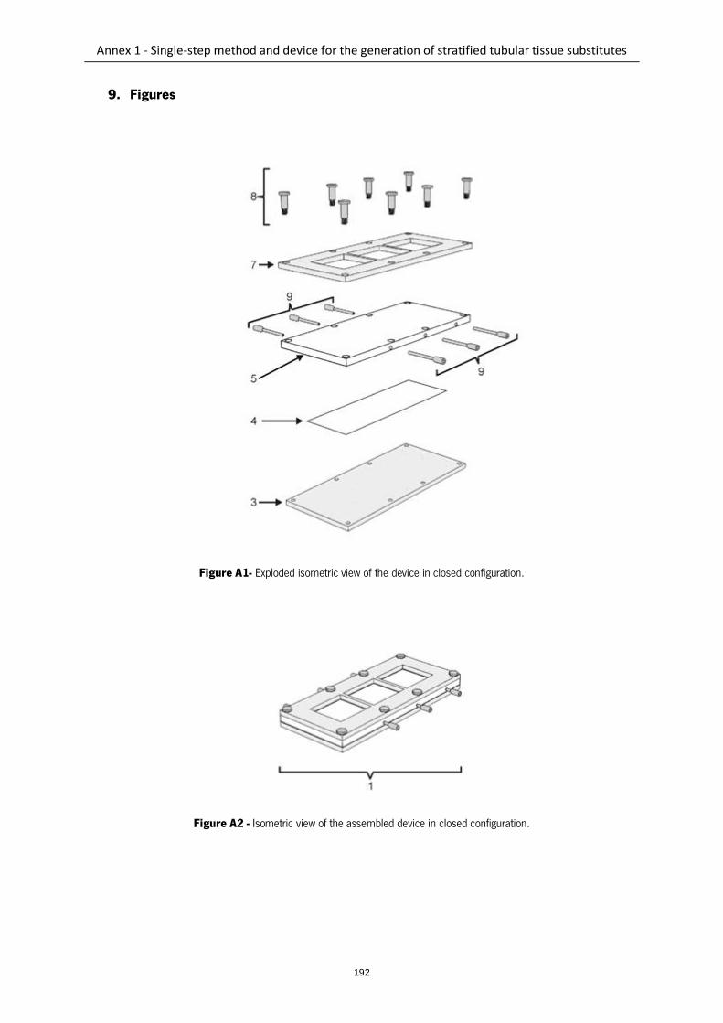
Annex 1 - Single-step method and device for the generation of stratified tubular tissue substitutes
192
9. Figures
Figure A1- Exploded isometric view of the device in closed configuration.
Figure A2 - Isometric view of the assembled device in closed configuration.
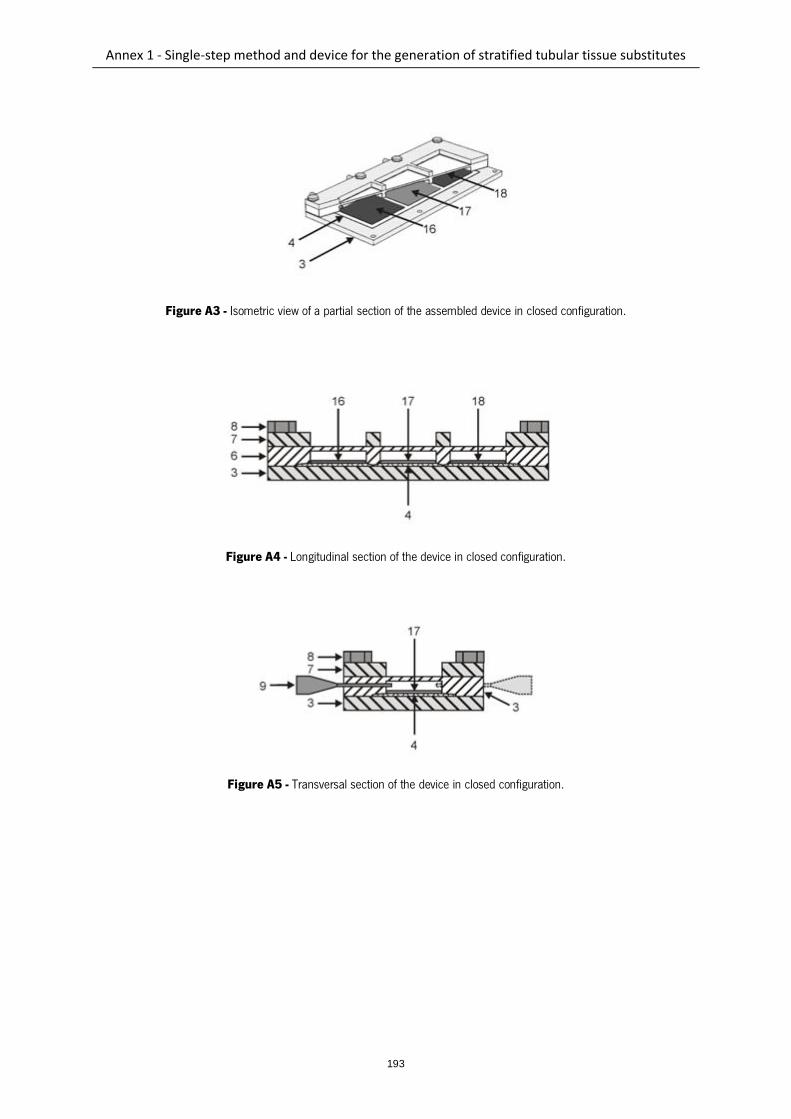
Annex 1 - Single-step method and device for the generation of stratified tubular tissue substitutes
193
Figure A3 - Isometric view of a partial section of the assembled device in closed configuration.
Figure A4 - Longitudinal section of the device in closed configuration.
Figure A5 - Transversal section of the device in closed configuration.
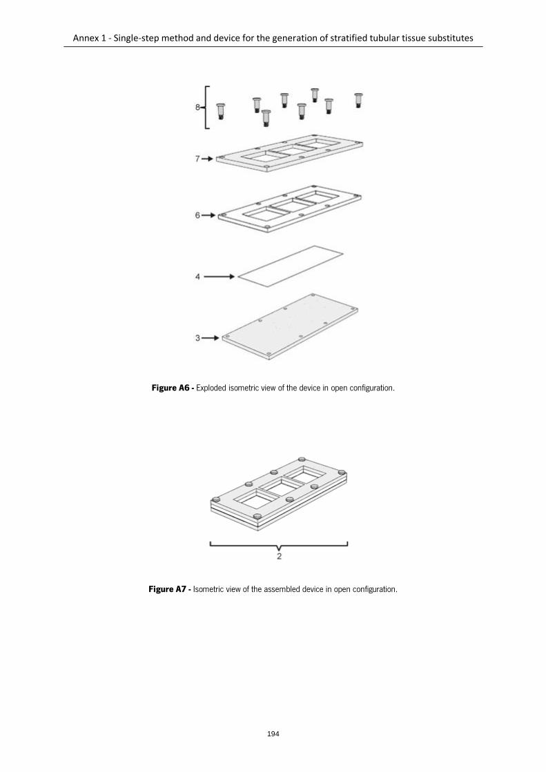
Annex 1 - Single-step method and device for the generation of stratified tubular tissue substitutes
194
Figure A6 - Exploded isometric view of the device in open configuration.
Figure A7 - Isometric view of the assembled device in open configuration.
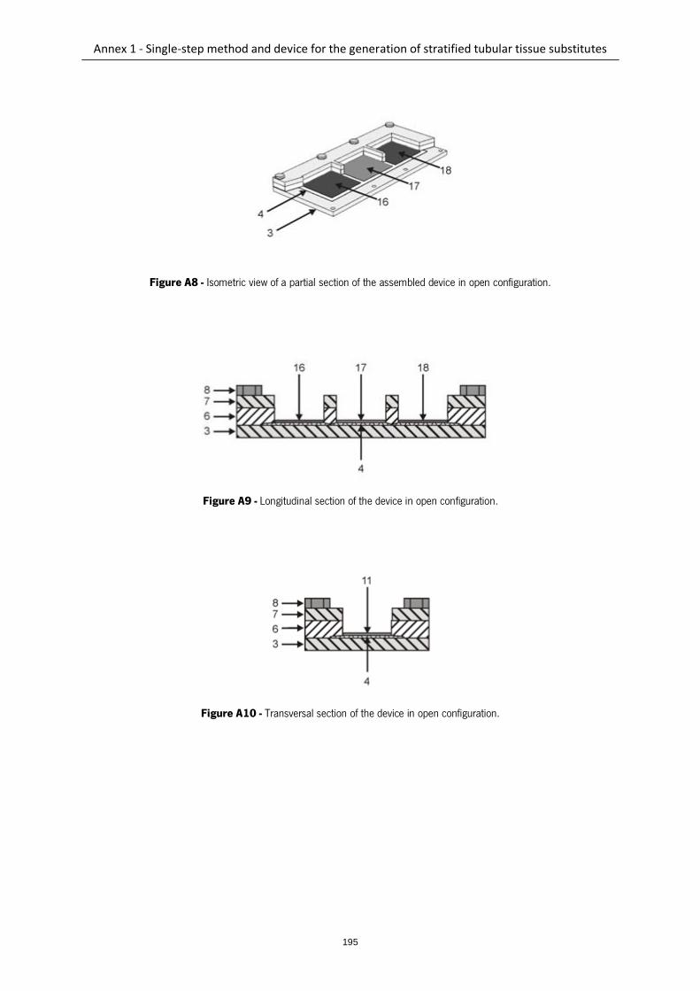
Annex 1 - Single-step method and device for the generation of stratified tubular tissue substitutes
195
Figure A8 - Isometric view of a partial section of the assembled device in open configuration.
Figure A9 - Longitudinal section of the device in open configuration.
Figure A10 - Transversal section of the device in open configuration.
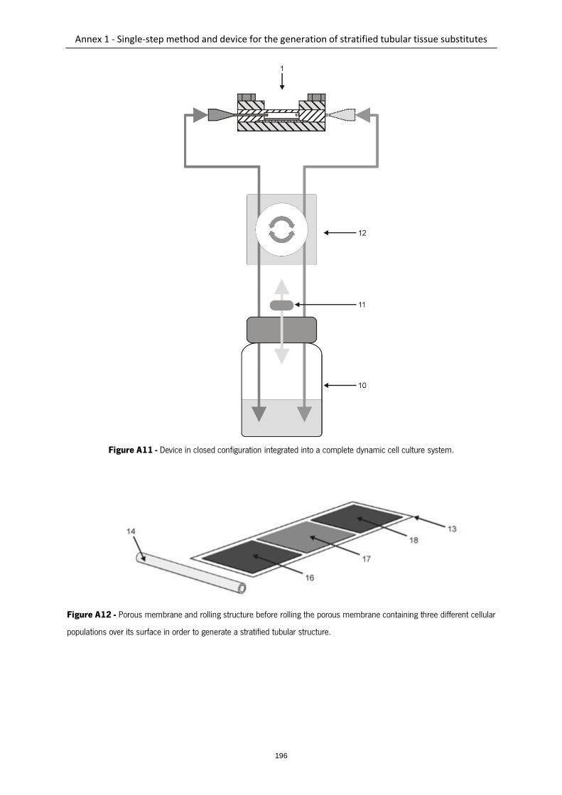
Annex 1 - Single-step method and device for the generation of stratified tubular tissue substitutes
196
Figure A11 - Device in closed configuration integrated into a complete dynamic cell culture system.
Figure A12 - Porous membrane and rolling structure before rolling the porous membrane containing three different cellular
populations over its surface in order to generate a stratified tubular structure.
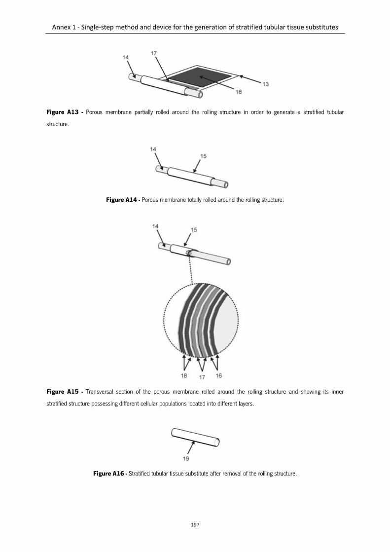
Annex 1 - Single-step method and device for the generation of stratified tubular tissue substitutes
197
Figure A13 - Porous membrane partially rolled around the rolling structure in order to generate a stratified tubular
structure.
Figure A14 - Porous membrane totally rolled around the rolling structure.
Figure A15 - Transversal section of the porous membrane rolled around the rolling structure and showing its inner
stratified structure possessing different cellular populations located into different layers.
Figure A16 - Stratified tubular tissue substitute after removal of the rolling structure.