v´aclav hlav´aˇc - cmp.felk.cvut.czcmp.felk.cvut.cz/cmp/courses/xe33pvr/lecture/camerashw.pdf ·...
TRANSCRIPT

1/39IMAGE ACQUISITION, CAMERAS
Vaclav Hlavac
http://cmp.felk.cvut.cz/∼hlavac

2/39IMAGING SYSTEMS
Pohled na celek: from the observed property of interest through radiance L
and irradiance E to an electrical signal and finally to a digital image.
Two options of image acquisition:
� Direct observation – there is one-to-one correspondence between a point
in the 3D scene and its 2D image (e.g., a ray in projective
transformation).
� Indirect observation – provides also a spatially dependent radiance L but
there is no one-to-one correspondence between 3D and 2D information
(e.g., radar, tomography, spectral imaging techniques, magnetic
resonance).
3/39
LIGHT POLARIZATION (1)
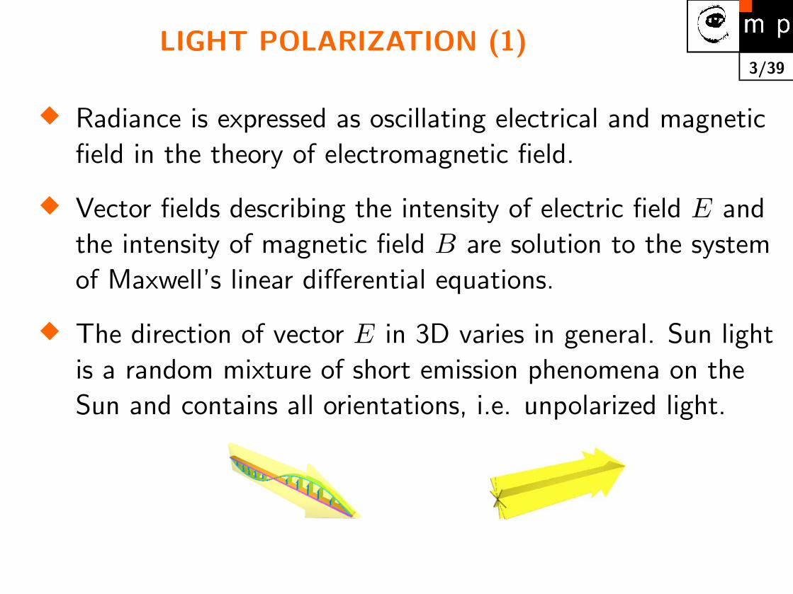
� Radiance is expressed as oscillating electrical and magnetic
field in the theory of electromagnetic field.
� Vector fields describing the intensity of electric field E and
the intensity of magnetic field B are solution to the system
of Maxwell’s linear differential equations.
� The direction of vector E in 3D varies in general. Sun light
is a random mixture of short emission phenomena on the
Sun and contains all orientations, i.e. unpolarized light.

4/39
LIGHT POLARIZATION (2)
� Harmonic planar wave is the solution to Maxwell’s
differential equations a free space (without electric
potentials and currents).
� The unpolarized light is polarized after passing through a
polarization filter. E.g., Iceland spar (in Czech dvojlomny
vapenec). Practical polarized filters = parallel fibres of
elongated molecules oriented in one direction.
� Examples: polarized spectacles for fishermen. Polarized
filter for a camera lens.

5/39
ILLUMINANTS ACCORDING TO EMISSION (1)
Day light – no flickering, unstable in time and color, very good
viewing colors.
Incandescent lamp – does not flicker, warms the device, big
energy input, big starting current, should be changed often,
good for viewing colors.
Halide lamp – no flickering, should be changed often, good for
viewing colors (better than incadescent lamp), smaller than
incadescent lamp.
Fluorescent lamp – flickering (it is possible to power it with
high frequency current or synchronize it), needs special
power source, long life, bad for viewing colors, close to
surface source (in Czech plosny zdroj).
6/39
ILLUMINANTS ACCORDING TO EMISSION (2)
LED – Light Emitting Diode, modulated light, no warming,
small size, low power consumption, monochromatic (also
infrared, white color), long life.
Laser – Light Amplification by Stimulated Emission of
Radiation). Device producing light of a single (pure) color
= monochromatic. Can be modulated, coherent (=same
phase) ⇒ problems with interferences, low power
consumption, long life for semiconductor lasers.
Flash tubes – e.g. xenon lamps, used in applications in which
big power is needed, very expensive.
7/39
ILLUMINANTS ACCORDING TO SIZE (1)
Point sources – e.g. halid lamp, LED, laser. Emphasize the
roughness of the surface. Strong highlights.
Surface sources, diffuse – e.g. reflection from a white opaque
wall, paper, fluorescent lamp, illuminants with large
focusing screen (in Czech matnice). Suppress the
roughness of the surface..
Back light diffuse – of advantage in the cases in which only
the silhouette of the object is of interest and the object is
thin (metal sheet, animal skin, . . . ). Very often used in
applications as it simplifies segmentation to objects and
background significantly. Suitable for gauging (in Czech
merenı rozmeru).
8/39
ILLUMINANTS ACCORDING TO SIZE (2)
Blacklight, telecentric – illuminants with collimators. Can be
used only for small objects (up to diameter of the lens
aperture), to be combined with telecentric lenses. Suitable
in cases in which silhouette of thin objects is of interest.
Dark field – oblique illumination when rays are not directed to
the lens, there is a reflection from object to the lens.

9/39OPTICAL TRICKS
Monochromatic filter can suppress ambient light and decrease
influence of color abberations.
Polarized filter removes or enhances polarized image, e.g.
reflection from glass cover of the device).
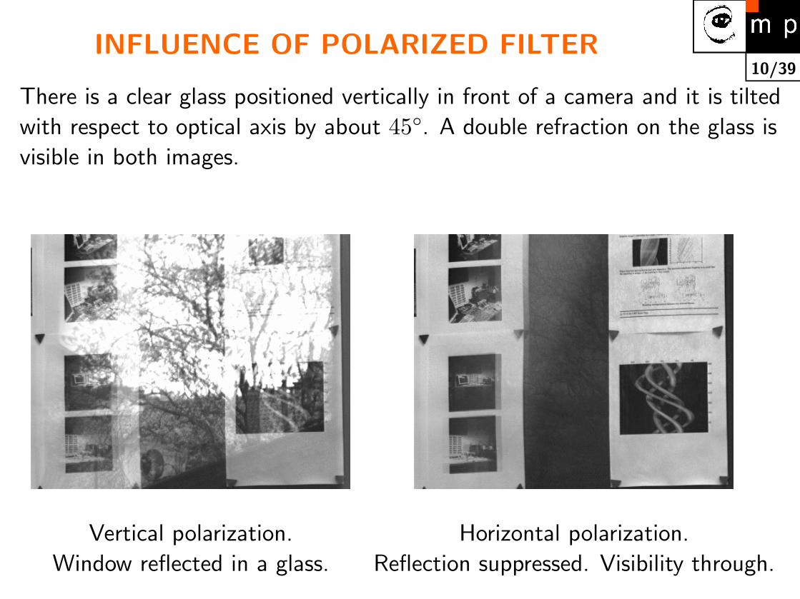
10/39INFLUENCE OF POLARIZED FILTER
There is a clear glass positioned vertically in front of a camera and it is tilted
with respect to optical axis by about 45◦. A double refraction on the glass is
visible in both images.
Vertical polarization. Horizontal polarization.
Window reflected in a glass. Reflection suppressed. Visibility through.

11/39DIRECTIONAL ILLUMINATION
� Irradiance of the opaque surface (ideal case: Lambertian)
depends on the surface direction. That is the reason why
the tilt of the surface can be measured (shape from
shading). One of the first applications was in measuring
shape of planetary surfaces, e.g. Venus craters.
� Shadows can generate edges in images which can be
confused with object boundaries..
� Mirror component of reflectance causes highlights. If this
the problem then directional illumination is not suitable.

12/39DIFFUSED ILLUMINATION
� Natural day light with overcast sky, fog.
� Solution in devices: circle from LEDs, semi-sphere from
LEDs.
� Useful for surfaces with significant mirror component of
reflectivity.

13/39BACKLIGHT ILLUMINATION
� Useful when the silhouette of the non-transparent object is
sought. Simplifies segmentation.
� Useful also for semi-transparent objects where a range of
interactions between light and matter can be observed
(refraction, absoption, diffusion of light). Local
inhomogeneities in the matter can be detected.
� Examples: X-ray. Spectral analysis when absorption
depends on frequency.
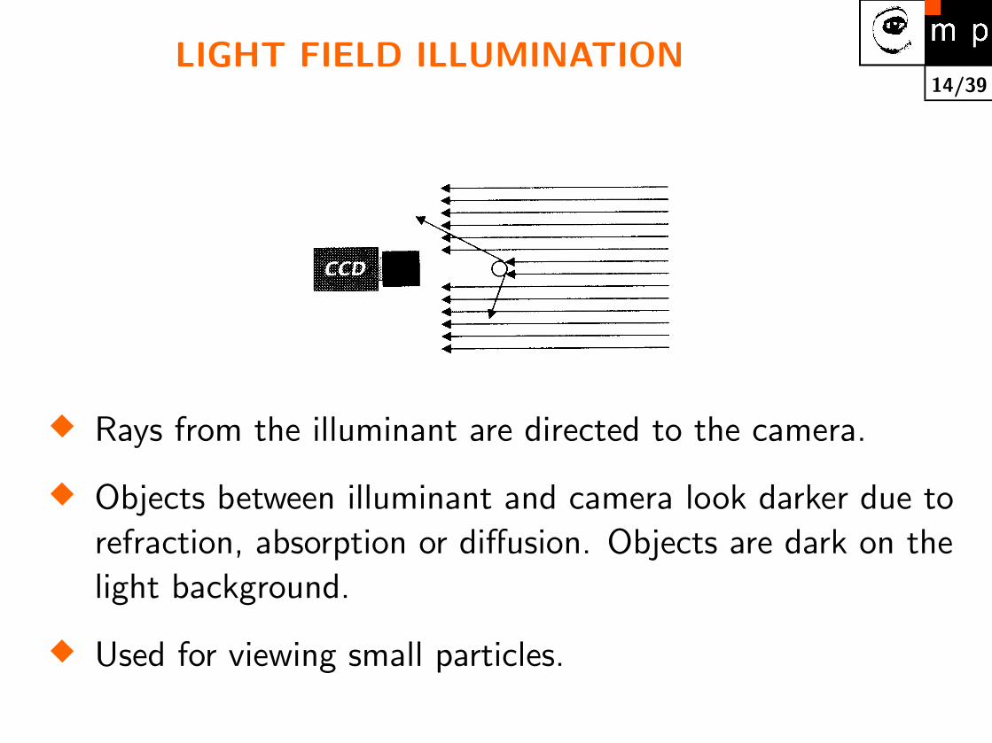
14/39LIGHT FIELD ILLUMINATION
� Rays from the illuminant are directed to the camera.
� Objects between illuminant and camera look darker due to
refraction, absorption or diffusion. Objects are dark on the
light background.
� Used for viewing small particles.

15/39DARK FIELD ILLUMINATION
� Rays from the illuminant are not directed to the camera.
� Refraction, reflection, diffusion of light which falls to the
camera is visible. Objects are light on the dark
background..
� Used to visualize small particles, metallic surfaces in
microscopy (e.g., aluminium conductors in
microelectronics).

16/39TELECENTRIC ILLUMINATION
� A collimator secures parallel rays.
� Lenses of big parameters have to be used if objects are
large (often Fresnel lenses = steps-like lens from concentric
elements).
� The measured gauge is invariant to the distance of the
object from the lens.

17/39NORMAL LENS
Distance to the object � focal length.
Normal, wide-angle, telephoto lens.
Object
Lens
Chip
F
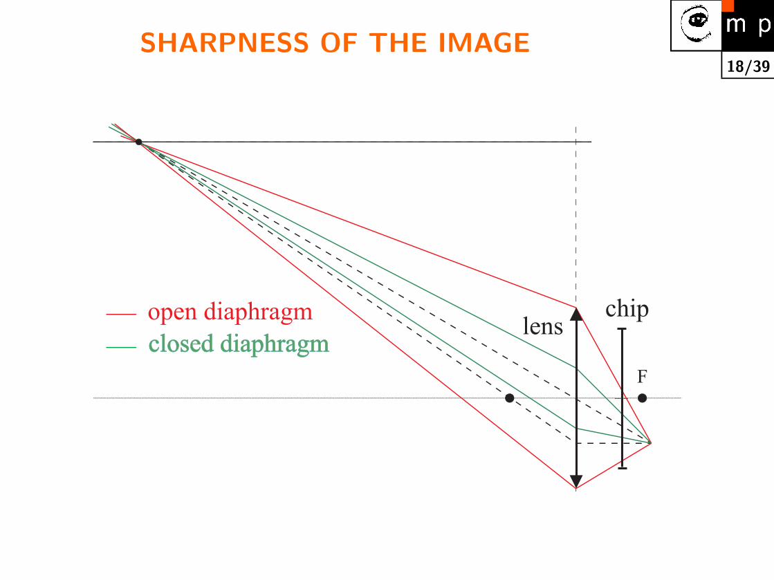
18/39SHARPNESS OF THE IMAGE
open diaphragm
closed diaphragmclosed diaphragmlens
chip
F
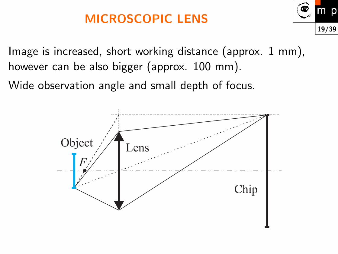
19/39MICROSCOPIC LENS
Image is increased, short working distance (approx. 1 mm),
however can be also bigger (approx. 100 mm).
Wide observation angle and small depth of focus.
F
Lens
Chip
Object

20/39TELECENTRIC LENS
� Only principal rays used, i.e. those parallel with optical axis.
� The input lens has to have bigger diameter than measured
object.
� Useful when measured object changes its position or the
object is ‘thick’.
Object
Collimator
Light source
Lens Diaphragm
Chip
F
21/39
PARAMETERS OF LENSES (1)
Focal length – fixed, adjustable (zoom) manually or motorized.
Working aperture, diaphragm (also speed of the lens) –
the smallest and the greatest aperture.
Diaphragm – fixed, adjustable manually or motorized..
Lens connecting
� C – the distance between the back of the lens and the
chip is approx. 17 mm.
� CS – approx 12 mm, the other parameters are the
same.
� Lens for C mount can be adjusted to CS mount by an
extension ring 5 mm thick, not possible in the other
direction CS to C.
22/39
PARAMETERS OF LENSES (2)
Focusing – Fix focus (e.g., web cameras), manual or motorized
focusing.
Distances in which object is in focus – can be changed by
extension rings in the expense of deteriorated optical
properties.
Format – which is the biggest chip usable; 1”, 2/3”, 1/2”,
1/3”, 1/4”.
Thread for a filter – clear filter is used to protect the lens.
Radial distortion – is not given in technical sheets but it is
important for measurement applications. Lenses with short
focal length have typically bigger radial distortions (several
pixels).
23/39
PRINCIPLE OF PHOTOCONVERSION INSEMICONDUCTORS
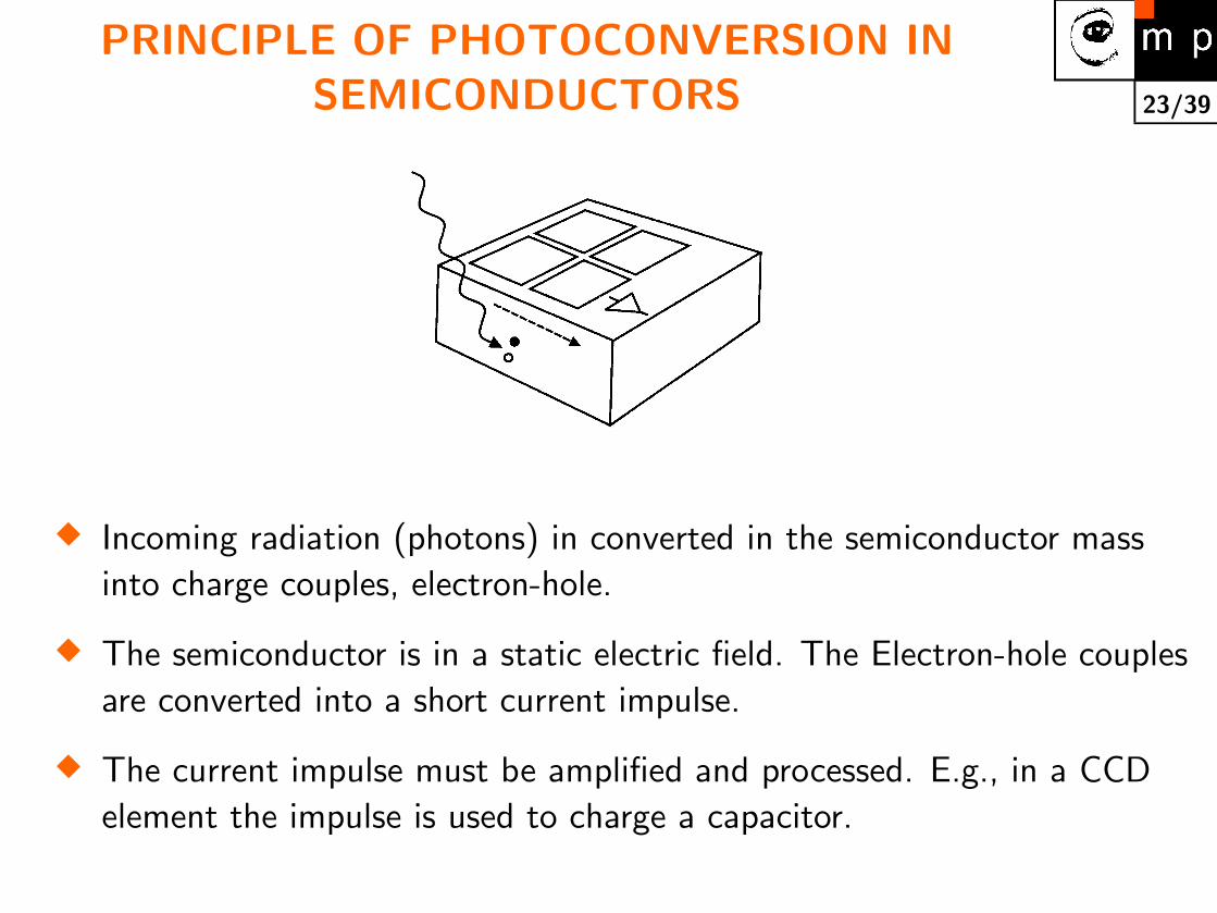
� Incoming radiation (photons) in converted in the semiconductor mass
into charge couples, electron-hole.
� The semiconductor is in a static electric field. The Electron-hole couples
are converted into a short current impulse.
� The current impulse must be amplified and processed. E.g., in a CCD
element the impulse is used to charge a capacitor.

24/39PHOTODIODE AND MOS STRUCTURE
Cross cut of two main principles for current generation andstoring the charge.


26/39
CCD CHIP, PROPERTIES OF THETECHNOLOGY
+ Linearity: CCD sensors explore conversion of a photon to
the couple electron-hole. The obtained charge is integrated
in a capacitor.
+ Low noise: is given by the integral character of the
measurement. Uncooled chip with TV read-out has SNR
approx. 60 dB.
+ Efficiency: Current sensors have hight energetic efficiency
approx. 40%, i.e. every third photon generates one couple
electron-hole.
– Read-out: only from the whole chip at once.
– Limited range of intensities: is given by the maximal
capacity of individual capacitors..
27/39
CMOS CHIP, PROPERTIES OF THETECHNOLOGY
http://www.ims-chips.de/products/vision/hdrc alt/hdrc ima.htmlhttp://www.imec.be/bohttp://www.vector-international.be/C-Cam/cmosccd.html
+ Logarithmic sensitivity: CMOS sensors are based on the
photo diode principle. They measure a current in a
read-out instance.
+ Read-out: possible in arbitrary order, e.g. only the region
of interest can be read-out.
+ Camera and processor on the same chip: CMOS
technology is well mastered (processors, memory). Smart
cameras.
– Higher noise:

28/39
CCD CAMERAS, USER’S VIEW (1)
� Spatial resolution: number of pixels in a row and in a
column. TV CCIR/PAL 768×576. TV RS170/NTSC
640×484. Non-television cameras also 2000×2000, keep
increasing.
� Resolution in intensity: given in bits for digital cameras,
output typically 8 bits also 12 bits. For analog cameras –
SNR, usually >50 dB.
� Sensitivity: v lux. Should be recalculated according to
used diaphragm and AGC.
� AGC: Automatic Gain Control; yes/no, can be switched
off?, manual control of gain.
� Shutter: commonly from 1/50 s to 1/10000 s.
29/39
CCD CAMERAS, USER’S VIEW (2)
� Format: size of the photosensitive chip. Given either in
inches of the equivalent vidicon tube diameter or in mm.
1/2” corresponds to 4.8×6.5 mm.
� Shape of a pixel: square pixel vs. non-square pixel.
� Output for automatic diaphragm:
� AWB: Automatic White Balance. Changes ratio of R and
B with respect to G.
� Gama correction: fixed/adjustable. Direct signal γ = 1.
Typicky γ = 0, 45 (enhances black). Compensates intensity
conversion function of the CRT (Cathode Ray Tube) and
adjusts it to the sensitivity of a human eye.
� Lens thread: C mount / CS mount.
30/39
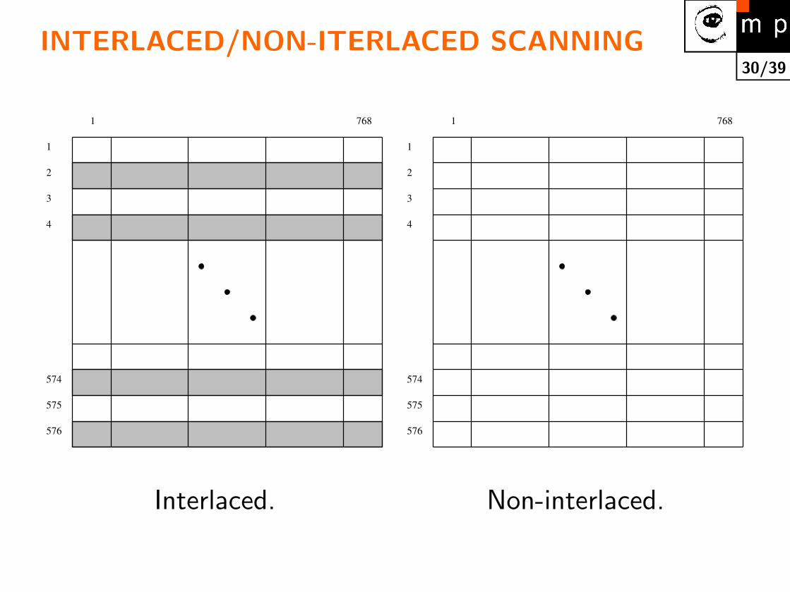
INTERLACED/NON-ITERLACED SCANNING
1
576
574
575
768
4
3
2
1
1
576
574
575
768
4
3
2
1
Interlaced. Non-interlaced.
31/39
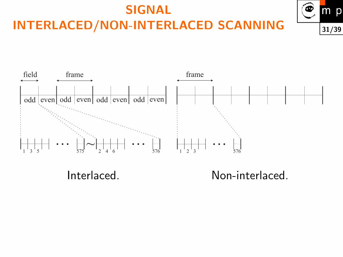
SIGNALINTERLACED/NON-INTERLACED SCANNING
framefield
1 23 45 6575 576
… …~
odd odd odd oddeven even even even
frame
1 2 3 576
…
Interlaced. Non-interlaced.

32/39ELECTRONIC SHUTTER
Shortened exposition is used either if there is too much light or
if fast events have to be captured.
tframe (noninterlaced)field (interlaced)
expositionI
33/39
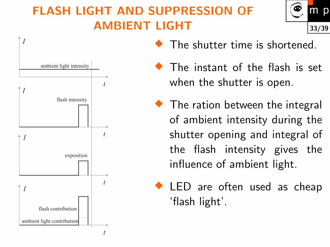
FLASH LIGHT AND SUPPRESSION OFAMBIENT LIGHT
t
t
t
exposition
t
ambient light intensity
flash intensity
flash contribution
ambient light contribution
I
I
I
I
� The shutter time is shortened.
� The instant of the flash is set
when the shutter is open.
� The ration between the integral
of ambient intensity during the
shutter opening and integral of
the flash intensity gives the
influence of ambient light.
� LED are often used as cheap
‘flash light’.
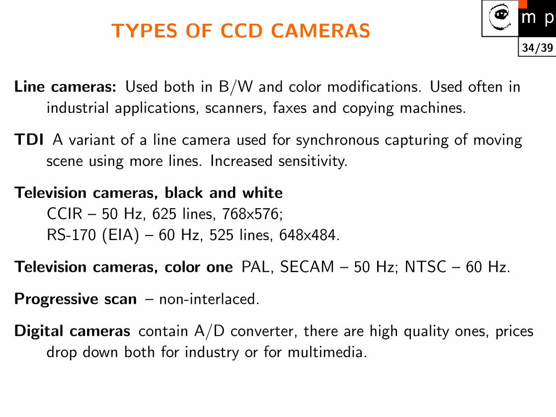
34/39TYPES OF CCD CAMERAS
Line cameras: Used both in B/W and color modifications. Used often in
industrial applications, scanners, faxes and copying machines.
TDI A variant of a line camera used for synchronous capturing of moving
scene using more lines. Increased sensitivity.
Television cameras, black and whiteCCIR – 50 Hz, 625 lines, 768x576;
RS-170 (EIA) – 60 Hz, 525 lines, 648x484.
Television cameras, color one PAL, SECAM – 50 Hz; NTSC – 60 Hz.
Progressive scan – non-interlaced.
Digital cameras contain A/D converter, there are high quality ones, prices
drop down both for industry or for multimedia.

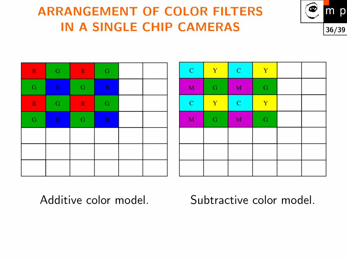
35/39COLOR CAMERAS SETUPS
� Manual change of color filters in front of the
monochromatic camera lens.
� Three chip cameras – an incoming light is divided to a
appropriate chip using color filters and semitransparent
mirrors.
� One chip camera has filters directly on a chip. Spatial
resolution in color resolution is smaller than coresponds to
the number of pixels.
36/39
ARRANGEMENT OF COLOR FILTERSIN A SINGLE CHIP CAMERAS
G
G
R G
B
G
B
G
R
G
R
B
B
G
G
R
M M G
C Y C Y
M G M G
C Y C Y
G
Additive color model. Subtractive color model.
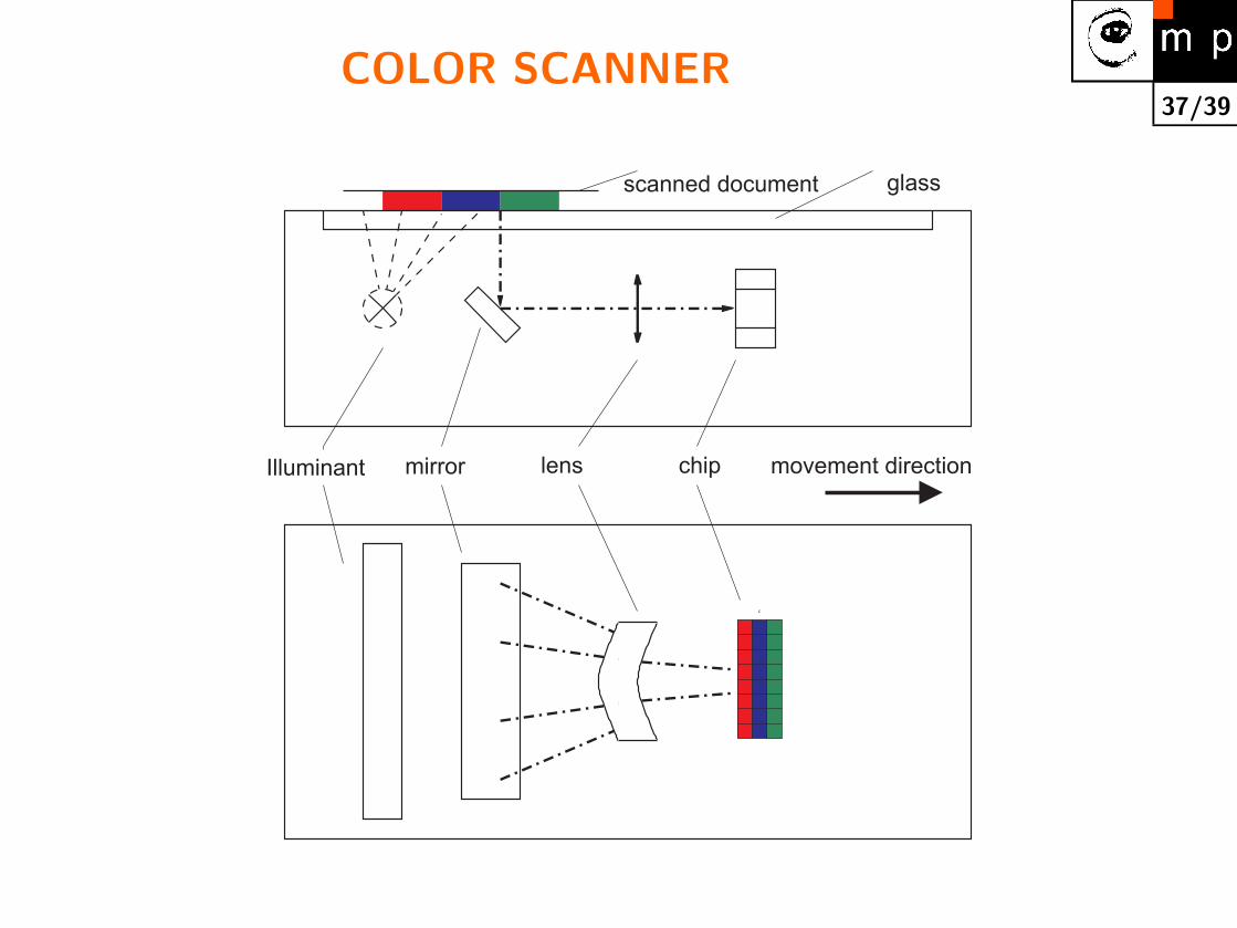
37/39COLOR SCANNER
c
Illuminant mirror lens chip movement direction
glassscanned document

38/39
FIRE WIRE (i.Link u Sony)
� A fast serial link. IEEE 1394.
� 2 types of transmission:
1. isochronous, e.g. images;
2. asynchronous, e.g. sending parameters to a device.
� Used also for disks, cameras, interconnection between
domestic electronics pieces (e.g., audio system Sony).
� Non-television camera. Example: color camera 1200×1024, 15 snmk/s, 40 thousands K.
� Two types of connectors. 4 pin and 6 pin one including
power sourse.
� Kabel max. 4.5 m. Repeaters
� The younger competitor to fire wire (IEEE 1394) is USB 2.

39/39A NEW BUS 1394b
� Substantial innovation. Speeds up to 3.2 Gb/s.
� Up to hundred meters 100 meters if transmitted on the
optical cable.
� Full backward compatibility with currently used
specifications 1394-1995 and 1394a.