universidade federal de santa catarina programa de … · “a menos que modifiquemos a nossa...
TRANSCRIPT
UNIVERSIDADE FEDERAL DE SANTA CATARINA PROGRAMA DE PÓS-GRADUAÇÃO EM CIÊNCIA E
ENGENHARIA DE MATERIAIS
André Luiz da Silva
CONFORMAÇÃO DE PORCELANATOS DE BAIXA ESPESSURA POR PRENSAGEM E TAPE CASTING
Dissertação submetida ao Programa de Pós-Graduação em Ciência e Engenharia de Materiais da Universidade Federal de Santa Catarina para a obtenção do Grau de Mestre em Ciência e Engenharia de Materiais. Orientador: Prof. Dr. Dachamir Hotza Coorientador: Prof. Dr. Adriano Michael Bernardin
Florianópolis
2012

André Luiz da Silva
CONFORMAÇÃO DE PORCELANATOS DE BAIXA ESPESSURA POR PRENSAGEM E TAPE CASTING
Esta Dissertação foi julgada adequada para obtenção do Título de
Mestre, e aprovada em sua forma final pelo Programa de Pós Graduação em Ciência e Engenharia de Materiais.
Florianópolis, 15 de outubro de 2012.
________________________ Prof. Dr. Antônio Pedro Novaes de Oliveira,
Coordenador do Programa Banca Examinadora:
________________________ Prof. Dr. Dachamir Hotza,
Orientador Universidade Federal de Santa
Catarina
________________________ Prof. Dr. Adriano Michael
Bernardin, Coorientador
Universidade do Extremo Sul Catarinense
________________________ Prof. Dr. João Batista
Rodrigues Neto, Universidade Federal de Santa
Catarina
________________________ Prof. Dr. Carlos Renato Rambo, Universidade Federal de Santa
Catarina
________________________ Dr. Fábio Gomes Melchiades, Universidade Federal de São
Carlos

1
Com muito carinho a minha amada esposa Caroline que sempre me apoiou em toda caminhada!

2
AGRADECIMENTOS
A Deus, nosso Criador, pela saúde, inteligência, amor e paciência que nos concede para enfrentar todas as barreiras e chegar à vitória.
Ao Professor Dr. Dachamir Hotza, meus sinceros agradecimentos
pela confiança em meu trabalho, pelos ensinamentos e pela excelente orientação que me concedeu.
Ao Professor Dr. Adriano Michael Bernardin, pela coorientação,
pelas contribuições e ensinamentos transmitidos nesse período. A minha amada esposa Caroline, pelo incentivo, apoio e
compreensão nos momentos difíceis, que se fez presente na motivação de todas as horas.
Aos meus pais José e Esmeraldina e aos meus sogros Adair e
Marlete pelo apoio. A empresa Cerâmica Urussanga SA, pelo uso dos laboratórios e
matérias-primas. A Universidade Federal de Santa Catarina pelas análises
realizadas. Aos professores pelas contribuições e conhecimentos adquiridos,
Dr. Carlos Renato Rambo, Dr. Antonio Pedro Novaes de Oliveira, Dr. Dachamir Hotza, Dr. Pedro Alberto Barbetta e Dr. Hansu Birol.
As novas amizades, Carla, Marcelo, Fernando, Jesus, Juliano,
Claudinei e Vitor pelas descontrações e estudos que juntos realizamos. Ao PGMAT-UFSC, pela oportunidade, assim como aos colegas
Rogério e Carlos pelo apoio. A todos, meu muito obrigado.
3
“A menos que modifiquemos a nossa maneira de pensar, não seremos capazes de resolver os problemas causados pela forma como nos acostumamos a ver o mundo”.
(Albert Einstein)
4
RESUMO
No presente trabalho foram avaliadas as características técnicas e microestruturas de um porcelanato industrial em diferentes espessuras. As propriedades avaliadas foram densidade aparente a verde, retração de queima, perda ao fogo, resistência mecânica, absorção de água, densidade aparente após queima, além da microestrutura. Foram estudados parâmetros de prensagem, como máxima pressão de compactação e ciclo de prensagem, além de analisada a queima em três temperaturas. Foi realizado ainda um estudo comparativo entre as propriedades técnicas e as microestruturas de porcelanatos de baixa espessura produzidos por prensagem ou tape casting. Os resultados mostraram que a redução da espessura do porcelanato, assim como a máxima temperatura de queima, afetam significantemente algumas características técnicas desses revestimentos, como microestrutura e propriedades físicas, tais como retração linear de queima, perda ao fogo, absorção de água, densidade aparente após queima e resistência mecânica. A máxima pressão de compactação em revestimentos de baixa espessura afeta parâmetros como retração linear de queima e densidade aparente a verde. Comparando-se a prensagem com o método de tape casting podem ser destacadas diferenças significativas na microestrutura e propriedades finais do material, como resistência mecânica e absorção de água. Palavras-chave: Porcelanato, Espessura, Prensagem, Tape casting.
5
ABSTRACT
In this work the mechanical properties and microstructure of porcelain tiles with different thicknesses were evaluated. The properties studied were bulk density, firing shrinkage, loss on ignition, mechanical strength, water absorption, bulk density after firing, as well as the microstructure. Pressing and sintering parameters, such as pressing pressure and cycle, and firing temperature were varied and analyzed. A comparative study was made between the technical properties and microstructure of low thickness porcelain produced by pressing and tape casting. The results showed that the reduction of the thickness of the porcelain, as well as the variation of the maximum firing temperature, significantly affect microstructure and technical characteristics of those porcelains, such as firing shrinkage, loss on ignition, water absorption, bulk density after firing and mechanical strength. The maximum pressing pressure in thin porcelain tiles affects parameters such as shrinkage and bulk density after firing. Comparing pressing and tape casting, differences in the microstructure and properties of the porcelain tiles were observed, such as mechanical strength and water absorption. Keywords: Porcelain tiles, Thickness, Pressing, Tape casting.
6
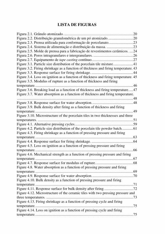
LISTA DE FIGURAS
Figura 2.1. Grânulo atomizado. ......................................................................... 20
Figura 2.2. Distribuição granulométrica de um pó atomizado. .......................... 20
Figura 2.3. Prensa utilizada para conformação de porcelanato. ......................... 23
Figura 2.4. Sistema de alimentação e distribuição da massa. ............................ 23
Figura 2.5. Molde de prensa para a fabricação de revestimentos cerâmicos. .... 24
Figura 2.6. Poros intragranulares e intergranulares. .......................................... 26
Figura 2.7. Equipamento de tape casting contínuo. ........................................... 27
Figure 3.1. Particle size distribution of the porcelain tile mixture. .................... 41
Figure 3.2. Firing shrinkage as a function of thickness and firing temperature. 43
Figure 3.3. Response surface for firing shrinkage. ............................................ 44
Figure 3.4. Loss on ignition as a function of thickness and firing temperature. 45
Figure 3.5. Modulus of rupture as a function of thickness and firing temperature. ....................................................................................................... 46
Figure 3.6. Breaking load as a function of thickness and firing temperature. .... 47
Figure 3.7. Water absorption as a function of thickness and firing temperature. ........................................................................................................................... 48
Figure 3.8. Response surface for water absorption. ........................................... 48
Figure 3.9. Bulk density after firing as a function of thickness and firing temperature. ....................................................................................................... 49
Figure 3.10. Microstructure of the porcelain tiles in two thicknesses and three temperatures. ..................................................................................................... 51
Figure 4.1. Alternative pressing cycles. ............................................................. 59
Figure 4.2. Particle size distribution of the porcelain tile powder batch. ........... 61
Figure 4.3. Firing shrinkage as a function of pressing pressure and firing temperature. ....................................................................................................... 63
Figure 4.4. Response surface for firing shrinkage. ............................................ 64
Figure 4.5. Loss on ignition as a function of pressing pressure and firing temperature. ....................................................................................................... 66
Figure 4.6. Mechanical strength as a function of pressing pressure and firing temperature. ....................................................................................................... 67
Figure 4.7. Response surface for modulus of rupture. ....................................... 68
Figure 4.8. Water absorption as a function of pressing pressure and firing temperature. ....................................................................................................... 69
Figure 4.9. Response surface for water absorption. ........................................... 70
Figure 4.10. Bulk density as a function of pressing pressure and firing temperature. ....................................................................................................... 71
Figure 4.11. Response surface for bulk density after firing. .............................. 72
Figure 4.12. Microstructure of the ceramic tiles with two pressing pressure and three temperatures. ............................................................................................ 73
Figure 4.13. Firing shrinkage as a function of pressing cycle and firing temperature. ....................................................................................................... 75
Figure 4.14. Loss on ignition as a function of pressing cycle and firing temperature. ....................................................................................................... 75

7
Figure 4.15. Modulus of rupture as a function of pressing cycle and firing temperature. .......................................................................................................76
Figure 4.16. Water absorption as a function of pressing cycle and firing temperature. .......................................................................................................76
Figure 4.17. Bulk density after firing as a function of pressing cycle and firing temperature. .......................................................................................................77
Figure 5.1. Particle size distribution of the porcelain tile batch. ........................86
Figure 5.2. Green microstructure of the ceramic tiles: a) Pressing; b) Tape Casting. ..............................................................................................................88
Figure 5.3. Firing shrinkage of the tiles formed by tape casting and dry pressing. ...........................................................................................................................89
Figure 5.4. Loss on ignition of the tiles formed by tape casting and dry pressing. ...........................................................................................................................90
Figure 5.5. Mechanical strength of the tiles formed by tape casting and dry pressing. .............................................................................................................91
Figura 5.6. Breaking load of the tiles formed by tape casting and dry pressing.92
Figure 5.7. Water absorption of the tiles formed by tape casting and dry pressing. .............................................................................................................93
Figure 5.8. Microstructure of the ceramic tiles formed by Tape Casting and Dry pressing. .............................................................................................................95
Figure 5.9. XRD of the porcelain tiles formed by pressing. ..............................96
Figure 5.10. XRD of the porcelain tiles formed by tape casting. .......................97

8
LISTA DE TABELAS
Tabela 2.1. Módulo de resistência à flexão e carga de ruptura de acordo com a absorção de água dos revestimentos prensados [6]. ........................................... 16
Tabela 2.2. Resistência mecânica para porcelanato técnico e esmaltado para área do produto > 50 cm² e espessura (e) variável segundo a NBR 15.463 [7]. ........ 16
Tabela 2.3. Características dos processos de conformação [26]. ....................... 21
Tabela 2.4. Aditivos típicos para cerâmica [35]. ............................................... 29
Table 3.1. Chemical analysis by XRF (wt%) of raw materials. ......................... 41
Table 3.2. Size distribution of the spray-dried granules. ................................... 42
Table 3.3. Bulk density of the tiles according to the thickness. ......................... 42
Table 4.1. Chemical analysis by XRF (wt%) of raw materials. ......................... 60
Table 4.2. Size distribution of the spray-dried granules. ................................... 61
Table 4.3. Bulk density of the tiles as a function of the pressing pressure. ....... 62
Table 4.4. Bulk density as a function of the pressing cycle. .............................. 74
Table 5.1. Typical thicknesses of films produced by tape casting. .................... 82
Table 5.2. Chemical analysis (wt%, XRF) of raw materials. ............................. 85
Table 5.3. Size distribution of the spray-dried powder. ..................................... 86
Table 5.4. Bulk density of the tiles formed by tape casting and dry pressing. ... 87
9
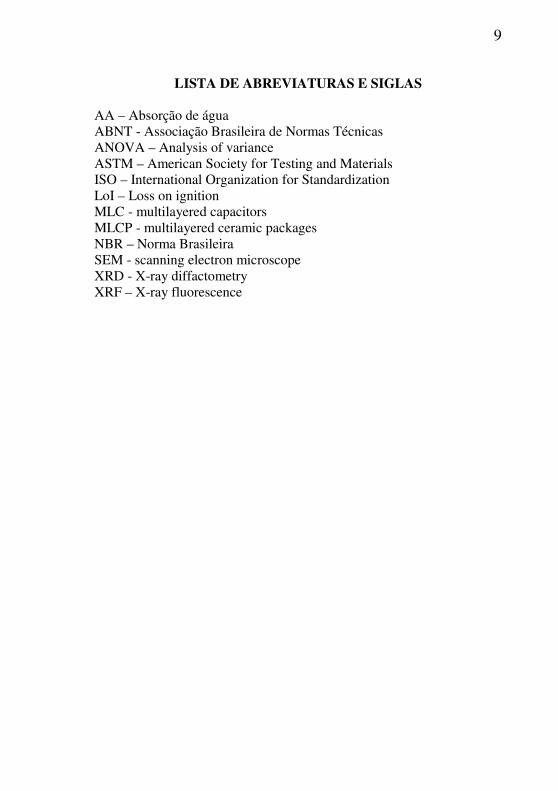
LISTA DE ABREVIATURAS E SIGLAS
AA – Absorção de água ABNT - Associação Brasileira de Normas Técnicas ANOVA – Analysis of variance ASTM – American Society for Testing and Materials ISO – International Organization for Standardization LoI – Loss on ignition MLC - multilayered capacitors MLCP - multilayered ceramic packages NBR – Norma Brasileira SEM - scanning electron microscope XRD - X-ray diffactometry XRF – X-ray fluorescence
10
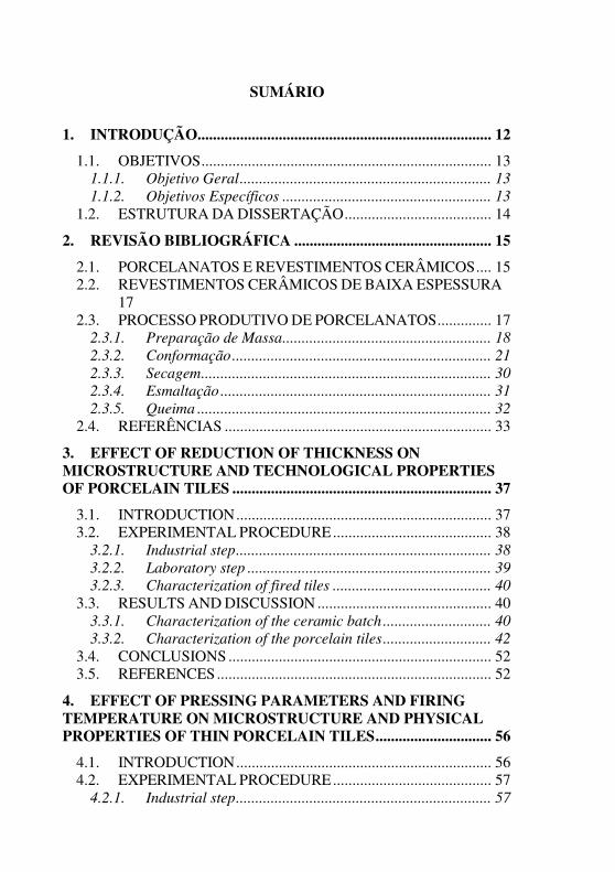
SUMÁRIO
1. INTRODUÇÃO ............................................................................ 12
1.1. OBJETIVOS ........................................................................... 13 1.1.1. Objetivo Geral ................................................................. 13 1.1.2. Objetivos Específicos ...................................................... 13
1.2. ESTRUTURA DA DISSERTAÇÃO ...................................... 14
2. REVISÃO BIBLIOGRÁFICA ................................................... 15
2.1. PORCELANATOS E REVESTIMENTOS CERÂMICOS .... 15 2.2. REVESTIMENTOS CERÂMICOS DE BAIXA ESPESSURA 17 2.3. PROCESSO PRODUTIVO DE PORCELANATOS .............. 17
2.3.1. Preparação de Massa ...................................................... 18 2.3.2. Conformação ................................................................... 21 2.3.3. Secagem ........................................................................... 30 2.3.4. Esmaltação ...................................................................... 31 2.3.5. Queima ............................................................................ 32
2.4. REFERÊNCIAS ..................................................................... 33
3. EFFECT OF REDUCTION OF THICKNESS ON MICROSTRUCTURE AND TECHNOLOGICAL PROPERTIES OF PORCELAIN TILES ................................................................... 37
3.1. INTRODUCTION .................................................................. 37 3.2. EXPERIMENTAL PROCEDURE ......................................... 38
3.2.1. Industrial step .................................................................. 38 3.2.2. Laboratory step ............................................................... 39 3.2.3. Characterization of fired tiles ......................................... 40
3.3. RESULTS AND DISCUSSION ............................................. 40 3.3.1. Characterization of the ceramic batch ............................ 40 3.3.2. Characterization of the porcelain tiles ............................ 42
3.4. CONCLUSIONS .................................................................... 52 3.5. REFERENCES ....................................................................... 52
4. EFFECT OF PRESSING PARAMETERS AND FIRING TEMPERATURE ON MICROSTRUCTURE AND PHYSICAL PROPERTIES OF THIN PORCELAIN TILES .............................. 56
4.1. INTRODUCTION .................................................................. 56 4.2. EXPERIMENTAL PROCEDURE ......................................... 57
4.2.1. Industrial step .................................................................. 57

11
4.2.2. Laboratory step................................................................ 58 4.2.3. Characterization of fired tiles .......................................... 59
4.3. RESULTS AND DISCUSSION ............................................. 60 4.3.1. Characterization of the ceramic batch ............................ 60 4.3.2. Characterization of the ceramic tiles............................... 62
4.4. CONCLUSIONS .................................................................... 77 4.5. REFERENCES ....................................................................... 78
5. FORMING OF THIN CERAMIC TILES THICKNESS: A COMPARISON BETWEEN TAPE CASTING AND DRY PRESSING ........................................................................................... 81
5.1. INTRODUCTION .................................................................. 81 5.2. EXPERIMENTAL PROCEDURE ......................................... 83
5.2.1. Industrial step .................................................................. 83 5.2.2. Laboratory step................................................................ 83 5.2.3. Characterization of fired tiles .......................................... 84
5.3. RESULTS AND DISCUSSION ............................................. 85 5.3.1. Characterization of the ceramic batch ............................ 85 5.3.2. Characterization of the ceramic tiles............................... 87
5.4. CONCLUSIONS .................................................................... 98 5.5. REFERENCES ....................................................................... 98
6. CONCLUSÕES GERAIS E SUGESTÕES PARA TRABALHOS FUTUROS ................................................................ 101
6.1. CONCLUSÕES .................................................................... 101 6.2. SUGESTÕES ........................................................................ 102

12
1. INTRODUÇÃO
Atualmente o Brasil é um dos principais protagonistas no mercado mundial de revestimentos cerâmicos, ocupando a segunda posição em produção e consumo. No ano de 2011, a produção nacional foi de 844,3 milhões de m². Em primeiro lugar, a China produziu 6,5 bilhões de m² [1].
O setor brasileiro de revestimentos cerâmicos é constituído por mais de 90 empresas, divididas em dois processos produtivos distintos em seu parque industrial: a via seca e a via úmida. O primeiro representa 72% da produção nacional e o segundo 28% [1].
O porcelanato é geralmente produzido pelo processo via úmida. No ano de 2011, a produção no Brasil foi de 72 milhões de m², o que representa 8,5% da produção nacional [1]. Em 1999 este índice era de aproximadamente 0,8% [2].
A competitividade no mercado atual e seu dinamismo motivam cada vez mais a busca por soluções inovadoras que agregam valor ao produto final.
Porcelanatos com espessura reduzida já estão sendo produzidos em empresas. A produção desses revestimentos normalmente está associada à utilização de ligantes, que conferem maior resistência mecânica à peça.
Revestimentos de baixa espessura conferem leveza e agregam valor ao produto, melhoram as condições de manuseio dos materiais durante a etapa de assentamento, além de proporcionar a diminuição do espaço ocupado pelo material nas empresas, melhorando a logística empresarial e facilitando o transporte.
Com a produção desses materiais, diminui-se a quantidade de matérias-primas por m² de material e economiza-se energia térmica durante a secagem e queima. Apesar de diminuir os custos de produção, aumenta-se o valor agregado do revestimento, e assim a lucratividade da empresa.
Procura-se, neste trabalho, avaliar como as propriedades de um porcelanato industrial são afetadas com a diminuição de sua espessura, estudar a influência da pressão de compactação e ciclo de prensagem e ainda comparar os métodos de conformação por prensagem e tape
casting em revestimentos de baixa espessura.
13
1.1. OBJETIVOS
1.1.1. Objetivo Geral
O presente trabalho tem por objetivo geral avaliar a alteração da microestrutura e das propriedades físicas de um porcelanato industrial em função da redução de sua espessura, produzidas por prensagem ou tape casting. 1.1.2. Objetivos Específicos
• Estudar o efeito da redução da espessura na microestrutura e nas propriedades físicas de um porcelanato industrial.
• Estudar o efeito da pressão de compactação, ciclo de
prensagem e temperatura máxima de queima na microestrutura e nas propriedades físicas de porcelanatos de baixa espessura.
• Comparar o efeito da conformação de porcelanatos de
pequena espessura, analisar as propriedades físicas e a microestrutura de um porcelanato conformado por prensagem e por tape casting.

14
1.2. ESTRUTURA DA DISSERTAÇÃO
A apresentação dos resultados da dissertação está organizada na forma de artigos científicos, escritos em inglês e encontra-se dividida em três etapas:
• Efeito da redução da espessura na microestrutura e propriedades físicas de porcelanatos (capítulo 3);
• Efeito da pressão, ciclo de prensagem e máxima temperatura de queima na microestrutura e propriedades físicas de porcelanatos de baixa espessura (capítulo 4);
• Conformação de revestimentos cerâmicos de baixa espessura: comparação entre o método de tape casting e prensagem a seco (capítulo 5).
Além disso, no capítulo 2, apresenta-se uma breve fundamentação teórica sobre o tema. Por fim, no capítulo 6, são apresentadas as conclusões gerais e sugestões para trabalhos futuros.

15
2. REVISÃO BIBLIOGRÁFICA
A produção de porcelanatos de baixa espessura é uma inovação no mercado de revestimentos cerâmicos. Esta revisão apresenta os princípios científicos e tecnológicos envolvidos na fabricação desses revestimentos, especialmente na produção de porcelanatos. A ênfase do processo é a etapa de conformação, principalmente os processos de prensagem a seco e colagem de fitas.
2.1. PORCELANATOS E REVESTIMENTOS CERÂMICOS Historicamente, o termo “porcelanato” surgiu no final de 1970, na
Itália, para designar um material de alto desempenho, caracterizado por uma aparência natural, assemelhando-se à rocha ou pedra natural mais do que qualquer outro produto cerâmico [3]. Inicialmente, a expressão “grés porcelanato” derivou das seguintes terminologias:
• “grés”, que consiste em um material cerâmico com estrutura compacta, característica de uma fase cristalina imersa em uma fase vítrea,
• “porcelanato”, terminologia que se refere às características técnicas dos produtos, os quais se assemelham às porcelanas [2].
O porcelanato possui ainda ótimas propriedades em relação à resistência ao gelo, resistência mecânica à flexão e compressão, ataque químico e manchas [4-5].
Os revestimentos cerâmicos podem ser classificados em função de seu acabamento superficial em esmaltados ou não esmaltados; pelo modo de conformação, em prensados, extrudados ou fabricados por outras técnicas; e ainda pelo grupo de absorção de água (AA) [4]. A tabela 2.1 apresenta a resistência mecânica requerida pela NBR 13.818 (1997), para os revestimentos de acordo com a absorção de água [6].
Em 2007 a ABNT (Associação Brasileira de Normas Técnicas) publicou a norma NBR 15.463, a qual é uma norma brasileira específica para porcelanato [4]. Destaca-se nesta norma a definição do produto porcelanato a partir do parâmetro absorção de água [7]:
• Porcelanato técnico: placa cerâmica não esmaltada para revestimento que apresenta absorção de água menor ou igual a 0,1%;
16
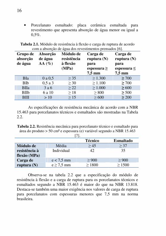
• Porcelanato esmaltado: placa cerâmica esmaltada para revestimento que apresenta absorção de água menor ou igual a 0,5%.
Tabela 2.1. Módulo de resistência à flexão e carga de ruptura de acordo
com a absorção de água dos revestimentos prensados [6]. Grupo de absorção de água
Absorção de água AA (%)
Módulo de resistência à flexão (MPa)
Carga de ruptura (N) para espessura ≥ 7,5 mm
Carga de ruptura (N) para espessura ≤ 7,5 mm
BIa 0 a 0,5 ≥ 35 ≥ 1.300 ≥ 700 BIb 0,5 a 3 ≥ 30 ≥ 1.100 ≥ 700 BIIa 3 a 6 ≥ 22 ≥ 1.000 ≥ 600 BIIb 6 a 10 ≥ 18 ≥ 800 ≥ 500 BIII > 10 ≥ 15 ≥ 600 ≥ 200
As especificações de resistência mecânica de acordo com a NBR
15.463 para porcelanatos técnicos e esmaltados são mostradas na Tabela 2.2.
Tabela 2.2. Resistência mecânica para porcelanato técnico e esmaltado para
área do produto > 50 cm² e espessura (e) variável segundo a NBR 15.463 [7].
Técnico Esmaltado Módulo de resistência à flexão (MPa)
Média ≥ 45 ≥ 37 Individual 42 35
Carga de ruptura (N)
e < 7,5 mm ≥ 900 ≥ 900 e ≥ 7,5 mm ≥ 1800 ≥ 1500
Observa-se na tabela 2.2 que a especificação do módulo de
resistência à flexão e a carga de ruptura para os porcelanatos técnicos e esmaltados segundo a NBR 15.463 é maior do que na NBR 13.818. Destaca-se também uma maior exigência nos valores de carga de ruptura para porcelanatos com espessuras menores que 7,5 mm na norma brasileira.
17
2.2. REVESTIMENTOS CERÂMICOS DE BAIXA ESPESSURA
Com o objetivo de melhorar a participação no mercado, os fabricantes de revestimentos cerâmicos buscam produtos inovadores. Particularmente, a tendência mais atual busca grandes formatos, com espessuras reduzidas e uma maior atenção a processos ambientalmente eficientes e sustentáveis [8]. Os revestimentos cerâmicos mencionados como produtos de baixa espessura, normalmente compreendem os materiais com espessura entre 3 e 5,5 mm, em formatos que variam de 30 × 90 cm a 100 × 300 cm [9-13].
Destacam-se inúmeras vantagens na fabricação de revestimentos cerâmicos de pequena espessura:
• Menor consumo de matérias-primas e recursos naturais; • Facilidade e versatilidade de instalação, novas possibilidades de
emprego de produtos com espessura e massa reduzidas (remodelagens e revestimentos externos);
• Maior facilidade de manipulação dos produtos; e • Redução significativa do espaço para estocagem (logística) e
menor custo de transporte (expedição) [8]. Aditivos, como ligantes, estão sendo usados para facilitar a
produção de revestimentos cerâmicos de baixa espessura. Os mais comuns são: polietilenoglicol [14], aditivos orgânicos, inorgânicos e híbridos orgânico-inorgânicos [8]. Esses aditivos conferem aos revestimentos uma maior resistência mecânica a seco e após queima, possibilitando a produção de revestimentos de baixa espessura mantendo as mesmas matérias-primas e processamento [8,14].
2.3. PROCESSO PRODUTIVO DE PORCELANATOS O processo industrial de porcelanatos inclui três principais
estágios: • Moagem a úmido e homogeneização das matérias-primas
naturais, seguido da secagem da suspensão por atomização; • Prensagem uniaxial com pressão entre 35 a 45 MPa do pó
atomizado com umidade de 5 a 7%; • Queima rápida de 40 a 60 min com temperatura entre 1180˚C a
1220˚C para obter a máxima densificação [3]. Apresenta-se a seguir uma descrição de cada etapa do processo de
fabricação de porcelanatos: preparação de massa, conformação,
18
secagem, esmaltação e queima. Ainda acrescenta-se na etapa de conformação o processo de colagem de fitas, mais conhecido como tape
casting, o qual atualmente é usado para fabricação de cerâmicas finas (0,1 a 1,5 mm), usadas geralmente em substratos de circuitos de computadores e estruturas de multicamadas.
2.3.1. Preparação de Massa
Para a preparação da massa de um porcelanato são utilizadas matérias-primas naturais, tais como, argilas, caulins e feldspatos.
Argila é um material natural de partículas finas, que apresenta plasticidade quando misturado com certa quantidade de água. Plasticidade é a propriedade do material se deformar sem romper pela aplicação de uma tensão, permanecendo deformado quando a tensão aplicada é retirada [15]. Do ponto de vista sedimentológico e granulométrico, argila compreende ao conjunto de partículas com dimensões inferiores a 2 µm ou 4 µm, segundo as escalas de Attemberg e Wentworth, respectivamente [16].
Mineralogicamente, os argilominerais (filossilicatos) são a constituição predominante das argilas. Seus tipos mais comuns são formados por folhas tetraédricas (T) e de silício e octaédricas (O) de alumínio, e com menor frequência, de magnésio e/ou ferro. Constituem unidades estruturadas na proporção 1:1 (TO) ou 2:1 (TOT). Além do arranjo estrutural, o espaçamento basal dessas unidades caracteriza os argilominerais dos diversos agrupamentos, destacando os grupos da caulinita, ilita e esmectita [16].
Caulim é o termo que se utiliza para referenciar toda rocha com percentual variável de minerais de argila, com composição igual ou próxima do mineral caulinita (2SiO2.Al2O3.2H2O). O caulim tem múltiplas aplicações e dependendo da qualidade é destinado para um ou outro uso. Podem-se destacar algumas propriedades inerentes a sua natureza, como a brancura, inércia aos agentes químicos, ausência de toxicidade e o tamanho fino de partícula. Desse ponto de vista se destaca na cerâmica para a fabricação de porcelanas e pavimentos [16,17].
Os feldspatos são usados com frequência como sinônimo de fundentes, apesar de serem diferentes e merecerem análises distintas. Na realidade os fundentes podem conter feldspatos. São usados na indústria cerâmica com a função básica de formar fase vítrea ou diminuir a temperatura de formação desta com a participação de outros componentes com maior grau de refratariedade [18].

19
Os feldspatos podem ser classificados em: feldspato potássico ou ortoclásio (K(AlSi3O8)); feldspato sódico ou albita (Na(AlSi3O8)); e feldspato cálcico ou anortita (Ca(Al2Si2O8)) [19]. Normalmente utilizam-se materiais com alto percentual de feldspato potássico para porcelanas decorativas e porcelanas de mesa. Para pavimentos grés de massa branca e grés porcelanato utilizam-se feldspatos sódicos e potássicos [18].
Uma alternativa de matéria-prima fundente para porcelanato é o filito. Esse é encontrado apenas no Brasil e vem sendo utilizado em cerâmica devido à estabilidade e melhoria de propriedades dimensionais, físicas e químicas, além do menor preço, quando comparado a outras fontes de potássio, como, por exemplo, os feldspatos. O filito cerâmico é uma rocha metassedimentar, muito fina, constituída basicamente de sericita, caulinita e quartzo, que se apresenta na natureza com diversas texturas e cores (vermelha, cinza, branca ou rósea) [20].
Após a pesagem das matérias-primas, as mesmas são levadas para a moagem. A moagem via úmida é realizada em moinhos de bolas, que consistem basicamente em um recipiente cilíndrico contendo em seu interior bolas de material duro de tamanhos variados, podendo ser um processo contínuo ou intermitente. Durante a moagem ocorre a redução do tamanho das partículas do material, é modificada a distribuição de tamanho das partículas, são dispersos os aglomerados e modificado o formato das partículas. O material a moer mistura-se com a água para facilitar a operação, sendo usados percentuais de água acima de 20% [21].
O material resultante da moagem é chamado de barbotina, que fica armazenado em tanques e em seguida é seco, geralmente por um atomizador. A operação de secagem por atomização tem por objetivo eliminar o excesso de água do processamento e obter um granulado, com as propriedades ideais para a conformação por prensagem: umidade, distribuição granulométrica, densidade aparente e aptidão ao escoamento. Na operação de secagem a barbotina é pulverizada por bicos atomizadores e bombas de pistão, a pressões próximas de 25 bar. O spray gerado entra em contato com ar quente (500-600ºC) formando o granulado (Figura 2.1), reduzindo a umidade de aproximadamente 25-40% para 5 a 7% [22].

20
Figura 2.1. Grânulo atomizado.
Fonte: Emiliani e Corbara, 2001 [23]. O pó atomizado formado possui uma distribuição granulométrica
(Figura 2.2), que junto com a umidade interferem em todo o processo, desde a fluidez do grânulo até a prensagem, influindo na densidade aparente compactada, absorção de água, resistência mecânica da peça e estabilidade dimensional de queima [24].
Figura 2.2. Distribuição granulométrica de um pó atomizado.
Fonte: Emiliani e Corbara, 2001 [23].
Uma boa distribuição granulométrica permite aos grânulos de diversos tamanhos um melhor empacotamento, de modo que aumenta a

21
densidade aparente do pó. O empacotamento dos grânulos menores tem muita importância para preencher os vazios entre as maiores [23].
A distribuição granulométrica é influenciada por diversos fatores: densidade e viscosidade da suspensão, pressão da bomba de alimentação, espessura do caracol, diâmetro do furo da pastilha e características dimensionais da câmara de atomização. A granulometria média diminui quando a viscosidade e a densidade da barbotina diminuem, a pressão da bomba aumenta, a espessura do caracol diminui e o diâmetro do furo da pastilha diminui. Caso contrário, a granulometria média aumenta [22]. 2.3.2. Conformação
Processos de conformação tornam uma mistura, barbotina, ou
materiais plásticos em uma forma definida. Existem muitos processos disponíveis para desempenhar esta função. Geralmente é desejável ter uma alta densidade a verde, pois isto restringe a retração de queima [25].
2.3.2.1. Processos de Conformação: Características Componentes cerâmicos são geralmente formados por misturas
de pó, cujas características são mostradas na Tabela 2.3. Para alcançar um corpo com propriedades uniformes é necessária uma compactação e uma queima uniformes [26].
Tabela 2.3. Características dos processos de conformação [26].
Técnica Prensagem a seco
Moldagem por injeção
Colagem de fitas
Extrusão
Material de partida
Grânulos Grânulos ou pasta
Barbotina Pasta
Teor de umidade (%)
0 – 10% 0 – 25% 25 – 50% 18 –25%
Automação Sim Contínuo Contínuo Contínuo Orientação de partículas
Sim Sim Sim Sim
22
Além das técnicas de conformação apresentadas na Tabela 2.3, podem ser citados também outros métodos, como colagem de barbotina, laminação e prensagem isostática [26]. Esta revisão limita-se ao estudo mais detalhado da conformação por prensagem a seco e colagem de fitas.
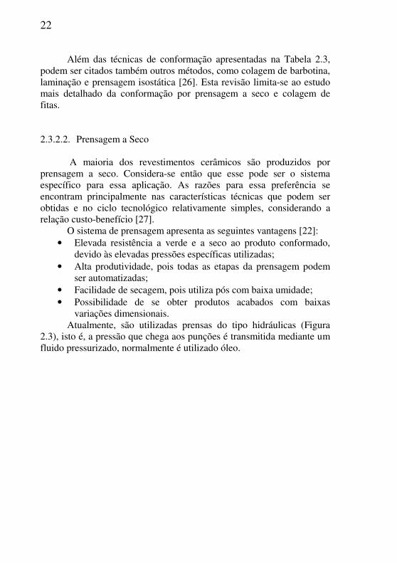
2.3.2.2. Prensagem a Seco A maioria dos revestimentos cerâmicos são produzidos por
prensagem a seco. Considera-se então que esse pode ser o sistema específico para essa aplicação. As razões para essa preferência se encontram principalmente nas características técnicas que podem ser obtidas e no ciclo tecnológico relativamente simples, considerando a relação custo-benefício [27].
O sistema de prensagem apresenta as seguintes vantagens [22]: • Elevada resistência a verde e a seco ao produto conformado,
devido às elevadas pressões específicas utilizadas; • Alta produtividade, pois todas as etapas da prensagem podem
ser automatizadas; • Facilidade de secagem, pois utiliza pós com baixa umidade; • Possibilidade de se obter produtos acabados com baixas
variações dimensionais. Atualmente, são utilizadas prensas do tipo hidráulicas (Figura
2.3), isto é, a pressão que chega aos punções é transmitida mediante um fluido pressurizado, normalmente é utilizado óleo.
23
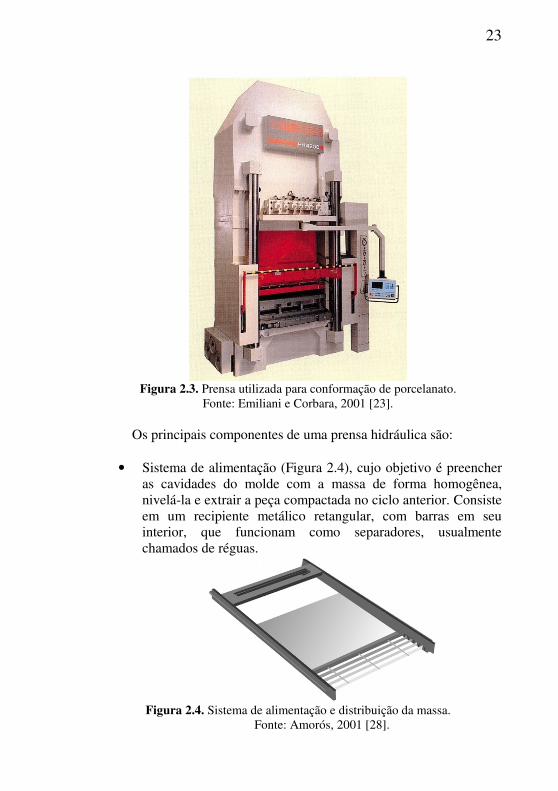
Figura 2.3. Prensa utilizada para conformação de porcelanato.
Fonte: Emiliani e Corbara, 2001 [23]. Os principais componentes de uma prensa hidráulica são:
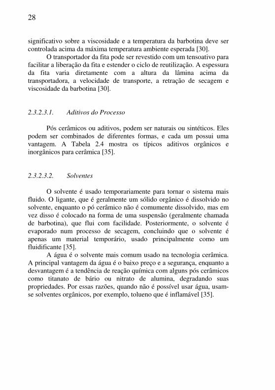
• Sistema de alimentação (Figura 2.4), cujo objetivo é preencher as cavidades do molde com a massa de forma homogênea, nivelá-la e extrair a peça compactada no ciclo anterior. Consiste em um recipiente metálico retangular, com barras em seu interior, que funcionam como separadores, usualmente chamados de réguas.
Figura 2.4. Sistema de alimentação e distribuição da massa.
Fonte: Amorós, 2001 [28].

24
• Sistema hidráulico, que consiste em um motor elétrico, uma
bomba de pistão e um trocador de calor. Esse sistema bombeia o óleo necessário para realizar as distintas operações que compõem o ciclo de prensagem.
• Sistema de prensagem, que compreende os elementos
mecânicos que realizam a compactação da massa e posteriormente a extração da peça. Esses elementos são: a travessa móvel, que se adere magneticamente ao punção (Figura 2.5), a matriz que contém as cavidades, cujo número e tamanho dependem do número e formato das peças que se deseja obter, e os punções inferiores móveis que estão localizados nas cavidades da matriz (Figura 2.5).
Figura 2.5. Molde de prensa para a fabricação de revestimentos cerâmicos.
Fonte: Amorós, 2001 [28].
• Sistema automatizado de controle, que regula eletronicamente o ciclo de prensagem.
2.3.2.2.1. Compactação
Quando o material granulado é submetido a uma tensão de
compressão elevada, podem ocorrer os seguintes processos, fenômenos ou trocas:
• Consolidação permanente do material, ou seja, um aumento na compactação do corpo, mesmo após a retirada da carga.

25
• Compressão elástica das partículas, ligantes e lubrificantes líquidos, que se desfaz quando a carga é eliminada, ocorrendo assim a expansão do material, chamada de expansão pós-prensagem.
• Fluxo de líquidos e gases dentre os poros do corpo por fluxo viscoso, devido aos gradientes de pressão estabelecidos ao longo dos distintos pontos da peça.
• Fricção entre as partículas e as paredes do molde que provoca uma distribuição heterogênea da pressão de compactação no volume do material [29].
A compactação de um grânulo causa a alteração de sua forma,
tamanho e do volume de seus poros, ocorrendo por três mecanismos:
• Redução do volume ocupado pelos poros intergranulares (Figura 2.6) e de seu volume pela reordenação e deslocamento dos grânulos.
• Diminuição do tamanho e volume dos espaços intergranulares por deformação plástica e/ou destruição dos grânulos que dependem das características mecânicas do grânulo (deformabilidade, resistência mecânica, dureza). Também ocorre nesta etapa o esmagamento dos grânulos ocos, geralmente presentes nas massas cerâmicas.
• Redução de tamanho e volume dos poros intragranulares pela reordenação e deslizamento das partículas buscando alcançar um empacotamento e máxima densidade [30]. Este último geralmente não ocorre nas pressões de prensagem utilizadas industrialmente na produção de porcelanatos.

26
Figura 2.6. Poros intragranulares e intergranulares.
Fonte: Reed, 1995 [30].
2.3.2.3. Tape Casting
O processo de tape casting foi originalmente desenvolvido por
Glenn N. Howatt como parte de um esforço para produzir materiais finos piezoelétricos durante a Segunda Guerra Mundial, em meados de 1940. Sua primeira publicação e registro de patentes foi em 1947-48. Em meados de 1950, John L. Park Jr da Corporação American Lava registrou uma patente que refinou a patente de Howatt, descrevendo uma suspensão não-aquosa, baseada em um suporte de polímero em movimento, como o poliéster. Refinamentos do processo básico descrito por Howatt e Park foram muitos, porém as etapas de processamento inicial delineadas por esses autores aplicam-se até hoje [31].
De acordo com Lee [1994], o termo casting é familiar para a maioria das pessoas da fundição de metal, onde o metal fundido é vazado num molde geralmente feito de areia. Porém, para a fabricação de cerâmica é usada uma suspensão, a base de água em temperatura ambiente [26].
Tape Casting ou colagem de fitas, é uma técnica bem estabelecida para a fabricação em grande escala de substratos cerâmicos e estruturas de multicamadas. Uma barbotina composta de pó cerâmico em um meio líquido, com adição de dispersantes, ligantes e plastificantes, é moldada sobre uma superfície estável ou em movimento. A barbotina é transmitida à superfície através de uma

27
lâmina com regulagem de altura, denominada Doctor Blade, que também contribui na medida da espessura final do revestimento [32].
As principais aplicações atuais incluem capacitores de multicamadas (MLC: multilayered capacitors) de titanato de bário, substratos para circuitos eletrônicos e pacotes cerâmicos de multicamadas (MLCP: multilayered ceramic packages) de alumina, de nitreto de alumínio e de vitrocerâmica [33].
Este processo revelou-se especialmente útil para produzir placas finas e planas de Al2O3 principalmente para a indústria eletrônica. Como um método de conformação cerâmica, é geralmente vantajoso para a preparação de placas finas uniformes, com áreas relativamente grandes e com alta densidade [34].
O processo inicia com a preparação de uma barbotina adequada. Suspensões não-aquosas são mais comumente usadas devido à maior facilidade de dispersão do pó e secagem da barbotina, mas por razões de saúde e meio ambiente é interessante um crescimento na colagem de fitas em sistema aquoso. Aditivos de processamento incluem um líquido/solvente, dispersante (defloculante), ligante, plastificante, e algumas vezes um surfactante [30].
Um equipamento de colagem de fitas é mostrado na Figura 2.7. A concentração de pó na barbotina deve ser alta e a viscosidade da barbotina de alimentação deve ser bem controlada [30].
Figura 2.7. Equipamento de tape casting contínuo.
Fonte: Reed, 1995 [30]. A barbotina deve ser pseudoplástica e ter uma viscosidade acima
de 4.000 mPa.s durante a colagem. A temperatura tem um efeito
28
significativo sobre a viscosidade e a temperatura da barbotina deve ser controlada acima da máxima temperatura ambiente esperada [30].
O transportador da fita pode ser revestido com um tensoativo para facilitar a liberação da fita e estender o ciclo de reutilização. A espessura da fita varia diretamente com a altura da lâmina acima da transportadora, a velocidade de transporte, a retração de secagem e viscosidade da barbotina [30].
2.3.2.3.1. Aditivos do Processo
Pós cerâmicos ou aditivos, podem ser naturais ou sintéticos. Eles
podem ser combinados de diferentes formas, e cada um possui uma vantagem. A Tabela 2.4 mostra os típicos aditivos orgânicos e inorgânicos para cerâmica [35].
2.3.2.3.2. Solventes
O solvente é usado temporariamente para tornar o sistema mais
fluido. O ligante, que é geralmente um sólido orgânico é dissolvido no solvente, enquanto o pó cerâmico não é comumente dissolvido, mas em vez disso é colocado na forma de uma suspensão (geralmente chamada de barbotina), que flui com facilidade. Posteriormente, o solvente é evaporado num processo de secagem, concluindo que o solvente é apenas um material temporário, usado principalmente como um fluidificante [35].
A água é o solvente mais comum usado na tecnologia cerâmica. A principal vantagem da água é o baixo preço e a segurança, enquanto a desvantagem é a tendência de reação química com alguns pós cerâmicos como titanato de bário ou nitrato de alumina, degradando suas propriedades. Por essas razões, quando não é possível usar água, usam-se solventes orgânicos, por exemplo, tolueno que é inflamável [35].

29
Tabela 2.4. Aditivos típicos para cerâmica [35]. Material Vantagens
Aquoso Não Aquoso
Solvente Água Barata e Segura
Etanol + tolueno Tricloroetano
Secagem rápida Não Inflamável
Dispersante Silicato de sódio Poliacrilato de amônio
Barato Nenhum Resíduo
Óleo de Peixe Polietilenoimina
Ampla gama Fácil evaporação
Ligante Amido Metil Celulose
Barato Gelificado com calor
Polivinil Butiral Emulsão de Acrilato
Efeito forte Fácil evaporação
Plastificante Etilenoglicol Glicerina
Barato Efeito Forte
Polietileno Glicol Octil Ftalato
Barato Agente de liberação
Lubrificante Emulsão de cera Estearato de amônio
Barato Homogêneo
Cera Ácido esteárico
Barato Efeito forte
2.3.2.3.3. Dispersante
Um dispersante, defloculante, agente umectante ou tensoativo,
reveste as partículas cerâmicas e as mantém numa suspensão estável devido a um impedimento estérico ou repulsão eletrostática [36]. Os defloculantes são usados por duas razões: para manter a suspensão com a viscosidade adequada e prevenir a aglomeração [35].

30
2.3.2.3.4. Ligante
Após a placa cerâmica ser conformada e o solvente ser
evaporado, o uso de um ligante deve promover uma considerável resistência mecânica, mesmo antes da queima do material. Assim os corpos crus adquirem resistência suficiente para serem manipulados para inspeção e carregamento do forno [35].
2.3.2.3.5. Plastificante
Um plastificante pode ser definido como um líquido que pode ser
adicionado à composição ligante para evitar a fragilidade do corpo seco. Um exemplo de um plastificante é a glicerina, que é usada com um ligante a base de álcool polivinílico [35].
2.3.3. Secagem
Em cerâmicas tradicionais, a etapa de secagem é responsável pela eliminação do líquido de processamento, que está no material prensado que acompanhou o grânulo atomizado. A umidade passa de aproximadamente 6,0 a 7,0% para valores inferiores a 1,0%. Os principais objetivos desta operação são:
• Aumentar a resistência mecânica do produto; • Garantir a uniformidade de temperatura na superfície da peça e
uma distribuição homogênea de umidade; • Assegurar que a temperatura de saída do secador seja constante
[22]. Em cerâmicas cujo método de conformação inicia-se a partir de
uma suspensão, como o tape casting, deve-se ter um cuidado ainda maior nessa etapa devido a elevada quantidade de solvente perdida durante esse processo.
A taxa de secagem varia diretamente com a concentração do solvente sobre a superfície, a temperatura e o teor de solvente no ar de secagem. Forças capilares transportam o líquido para a superfície seca. Ocorre a retração, e como o solvente é perdido, as partículas ficam mais próximas. As retrações ocorrem na espessura e comprimento da fita, a retração na espessura é aproximadamente metade da altura da lâmina do doctor blade. Segregações de partículas ou fases orgânicas não devem
31
ocorrer durante a secagem. Alguma migração do plastificante à superfície de secagem pode ocorrer, mas a migração de alto peso molecular é mínima quando as moléculas são adsorvidas pelos ligantes [30].
Trincas na superfície podem se formar quando o material próximo à superfície torna-se frágil e a retração diferencial produz uma tensão que excede a resistência à tração. Uma retração diferencial devido a um diferente conteúdo de líquido quando o produto foi formado ou a uma taxa diferenciada de secagem sobre a superfície do produto também pode produzir deformação. Idealmente, a secagem deve ocorrer de forma simétrica em um material isotrópico, e todas as retrações devem terminar antes do término da secagem [30]. 2.3.4. Esmaltação
Esmaltação é a etapa responsável pela decoração da superfície do revestimento cerâmico, sendo aplicada uma camada uniforme de esmalte que pode ser definido como um material vítreo [37].
Um esmalte é uma espécie de vidro transparente, incolor e quase sempre brilhante. Funde no forno e logo solidifica no resfriamento. Mas, se na base vítrea desse esmalte existir certas substâncias opacificantes, o esmalte se tornará opaco [37].
Os esmaltes são formados pela combinação de vários óxidos, que são formados basicamente, por uma estrutura vítrea, elementos modificadores de rede e elementos estabilizadores de rede:
• Estrutura vítrea: são os formadores de rede, unidades estruturais que não se repetem a distâncias regulares. Unidade básica: tetraedro: Si-O ou triangular: B-O.
• Elementos modificadores de rede: ocupam os interstícios da rede enfraquecendo os enlaces, diminuindo a energia de rompimento. Propriedades afetadas: fusibilidade, dureza, estabilidade da rede.
• Elementos estabilizadores da rede: evitam que o estado amorfo passe para o estado cristalino, isto é, dá estabilidade a estrutura amorfa, evitando a devitrificação [38].
A escolha do sistema de aplicação deve ser fundamentalmente definida pela textura superficial desejada no produto final, levando-se em consideração o seu comportamento na queima. Deve-se observar na escolha também o efeito estético e funcional que se deseja obter no
32
produto final. Dentre os sistemas utilizados, os mais comuns para produção de porcelanato são o véu campânula, pulverização e esmaltação a disco. Na aplicação por véu campânula, o véu é formado pelo deslizamento da suspensão sobre uma superfície convexa, na forma de uma taça invertida feita de aço inoxidável, criando um véu semicircular ou circular [21].
Atualmente na produção de revestimentos cerâmicos é utilizada uma camada intermediária entre a massa e o esmalte denominada engobe. O engobe tem as seguintes finalidades:
• Eliminar defeitos superficiais do corpo cerâmico, possibilitando melhor superfície do esmaltado;
• Assegura a constância das cores, independente da cor e qualidade da base cerâmica;
• Isolar a camada de esmalte do corpo cerâmico, a fim de eliminar as reações de decomposição que o esmalte fundido provoca nos componentes da massa e as desgaseificações que as acompanham.
A diferença fundamental entre o engobe e o esmalte é a quantidade reduzida de fase líquida que se forma no engobe e a temperatura de queima que depende de sua composição química [38].
2.3.5. Queima
As peças são submetidas a um tratamento térmico, promovendo as transformações necessárias para a obtenção das características estéticas e tecnológicas desejáveis nos produtos finais. Durante a queima ocorrem transformações que afetam o suporte e o vidrado, dependendo das matérias-primas e da temperatura atingida. O conhecimento dessas transformações permite estabelecer a melhor curva de queima para o material [22].
O processo de sinterização converte uma microestrutura verde em uma microestrutura de um componente cerâmico com certa densidade. Essa é a última etapa do processo que influencia no desenvolvimento microestrutural [39].
A temperatura ótima de queima é a temperatura na qual se obtém a mínima porosidade aberta no corpo cerâmico e a porosidade fechada ainda não começou a aumentar. A temperatura ótima de queima para porcelanato normalmente situa-se entre 1190 e 1220°C. A textura da

33
porosidade do produto nessa temperatura determina suas propriedades técnicas [40].
A densificação de um porcelanato envolve um processo de sinterização em fase líquida. Durante a queima, em temperaturas de aproximadamente 900 – 1000°C, uma importante quantidade de fase líquida começa a se formar. A pressão capilar deixam as partículas mais juntas, aumentando a retração linear e reduzindo a porosidade. Enquanto ao mesmo tempo é alterado o tamanho e a forma dos poros. Aumentando a temperatura, aumenta a quantidade de fase líquida e reduz a porosidade. Em estados intermediários, em torno de 1180°C, os poros começam a fechar e as conexões entre os poros são eliminadas. Os poros fechados contêm ar que exercem pressão contra as paredes, opondo a densificação. Em estados avançados do processo, acima de 1200°C, a pressão dos poros fechados é alta e neutraliza a pressão capilar, fazendo a expansão do produto [40].
2.4. REFERÊNCIAS
[1] ASSOCIAÇÃO NACIONAL DOS FABRICANTES DE CERÂMICA PARA REVESTIMENTOS: Anfacer. Disponível em: <www.anfacer.org.br> Acesso em: 26 de ago. 2012.
[2] MENEGAZZO, A.P.M. et al. Grés Porcelanato. Parte I: Uma Abordagem Mercadológica. Cerâmica Industrial, São Paulo, v.5, n.5, p.7-10, set/out. 2000.
[3] SÁNCHEZ, E. et al. Porcelain tile: Almost 30 years of steady scientific-technological evolution. Ceram. Int., v.36, p.831-845, 2010.
[4] OLIVEIRA, A.P.N. de; HOTZA, D. Tecnologia de fabricação de revestimentos cerâmicos. Editora UFSC, Florianópolis, 2011.
[5] HECK, C., Grés Porcelanato. Cerâmica Industrial, São Paulo, v.1, n.4/5, p.21-24, ago/dez. 1996.
[6] NBR 13818. Placas cerâmicas para revestimento: especificação e métodos de ensaios. Associação Brasileira de Normas Técnicas, 1997.
[7] NBR 15463. Placas cerâmicas para revestimento: porcelanato. Associação Brasileira de Normas Técnicas, 2007.
34
[8] VIVONA, D.; PICCININI, F. Espessuras Reduzidas para Grandes Formatos Eco-Eficientes. Cerâmica Industrial, São Paulo, v.14, n.4, p.7-10, jul/ago. 2009.
[9] FAP CERAMICHE. Gruppo Ceramiche Caesar Spa. Disponível em: <http://www.fapceramiche.com> Acesso em: 26 ago. 2011.
[10] LAMINAN. Disponível em: <http://www.laminam.it> Acesso em: 12 set. 2012.
[11] IMOLACERAMICA. Disponível em: <http://www.imolaceramica.it> Acesso em: 12 set. 2012.
[12] CERÂMICA PORTINARI. Disponível em: <www.ceramicaportinari.com.br> Acesso em: 12 set. 2012.
[13] CERÂMICA CEUSA. Disponível em: <www.ceusa.com.br> Acesso em: 12 set. 2012.
[14] NANDI, V.S.; MADALENA, J.R.; BERNARDIN, A.M. Redução de Espessura de Porcelanato Esmaltado: Desenvolvimento Laboratorial. Cerâmica Industrial, São Paulo, v.16, n.4, p.26-29, jul/ago. 2011.
[15] SANTOS, P.S. Ciência e Tecnologia de Argilas. São Paulo: Editora Edgard Blucher Ltda, v.1, p.3-4,1989.
[16] MOTTA, J. F. M. et al. As matérias-primas plásticas para a cerâmica tradicional: argilas e caulins, Cerâmica Industrial, São Paulo, v.9, n.2, p. 33-46, mar/abr. 2004.
[17] BARBA, A. et al. Matérias primas para la fabricación de soportes
de baldosas cerámicas. 2.ed. Castellón: Instituto de Tecnologia Cerámica, 2002.
[18] CASTELLÓ, J.B.C.; MUÑOZ, L.S. Matérias-primas y aditivos
cerámicos. Castellón: Faenza Editrice Ibérica, 2003.
[19] BIFFI, G. O grés porcelanato. Faenza Editrice do Brasil, 2002.
[20] T-COTA. Eng. e minerais industriais. Disponível em: <http://www.t-cota.com.br/> Acesso em: 30 out. 2012.
[21] BRISTOT, V.M. Máquinas e Equipamentos para Cerâmica. Editora: Luana, Criciúma/SC, 1996.
[22] FONSECA, A.T. Tecnologia do Processamento cerâmico. Lisboa: Universidade Aberta, 2000.

35
[23] EMILIANI, G.P.; CORBARA, F. Tecnologia cerâmica. 2.ed. Faenza: Gruppo Editoriale Faenza Editrice, 2001.
[24] LUNARDI, S. Estudo das variáveis que interferem na cor do
porcelanato técnico. T.C C. Tec.Cerâmica, Unesc, Criciúma, 2004.
[25] KING, A.G. Ceramic technology and processing. Norwich, NY, p.134, 2002.
[26] LEE, W.E.; RAINFORTH, W.M. Ceramic microstructures:
property control by processing. London, Chapman & Hall, 1994.
[27] GUERRIERI, G. et al. Raw Material Preparation and Forming of
Ceramic Tiles. Acimac: Associazione Costruttori Italiani Macchine Attrezzature per Ceramica, p.361–362, 2004.
[28] AMORÓS, A. J. A operação de Prensagem: Considerações Técnicas e sua Aplicação Industrial. Parte V: Descrição da Etapa de Prensagem, Cerâmica Industrial, São Paulo, v.6, n.3, p. 26-32, maio/jun. 2001.
[29] AMORÓS, A. J. A operação de Prensagem: Considerações Técnicas e sua Aplicação Industrial. Parte II: A Compactação, Cerâmica
Industrial, São Paulo, v.5, n.6, p.14-20, nov/dez. 2000.
[30] REED, J.S. Principles of ceramic processing. 2.ed. New York: John Wiley & Sons, Inc., 1995.
[31] TERPSTRA, R.A.; PEX, P.P.; VRIES, A.H. Ceramic Processing. 1.ed. Chapman & Hall. London, UK. 1995.
[32] HOTZA, D.; GREIL, P. Review: Aqueous tape casting of ceramic powders. Materials Science and Engineering. v.202, p.206-217, 1995.
[33] HOTZA, D. Artigo revisão: colagem de folhas cerâmicas. Cerâmica. v.43, p.157-164, 1997.
[34] ALBANO, M.; GARRIDO, L. Influence of the slip composition on the properties of tape-cast alumina substrates. Ceram. Int., v.31, p.57-66, 2005.
[35] SHANEFIELD, D.J. Organic Additives and Ceramic Processing. 2.ed. Boston / Dordrecht / London: Kluwer Adademic Publishers, 1999.
[36] KIENNEMANN, J. Drying mechanisms and stress development in aqueous alumina tape casting. J. Eur. Ceram. Soc., v.25, p.1551-1564, 2004.
36
[37] CHITI, J.F. Manual de Esmaltes Ceramicos Tomo 1, 3.ed. Ediciones Condorhuasi, Buenos Aires, Argentina, 1988.
[38] PRACIDELLI, S. Estudo dos Esmaltes Cerâmicos e Engobes. Cerâmica Industrial, São Paulo, v.13, n.1/2, p.8-20, jan/abr. 2008.
[39] RIEDEL, R.; CHEN I-W. Ceramics Science and Technology. V.1, Wiley-VCH Verlag GmbH & Co. KGaA, Weinheim, 2008.
[40] SÁNCHEZ, E. et al. Porcelain tile: Almost 30 years of steady scientific-technological evolution. Ceram. Int., v.36, p.831-845, 2010.

37
3. EFFECT OF REDUCTION OF THICKNESS ON MICROSTRUCTURE AND TECHNOLOGICAL PROPERTIES OF PORCELAIN TILES
3.1. INTRODUCTION
Porcelain stoneware is a material with outstanding technical properties such as mechanical, wear, frost and chemical resistance. In the last decade, the global production of porcelain tiles increased markedly when compared to other ceramic products. In fact, the technical properties of porcelain stoneware, coupled with improved aesthetic appearance, gave it a prominent role in the tile market [1-2]. Porcelain tiles are very compact, throughout vitrified and extremely low porous. This low porosity is an essential feature, making them frost resistant and therefore service able for outdoor flooring and wall cladding in cold climates [3-4]. The low porosity correspond to very low values of water absorption (<0.5% according to the ISO 13006 standard [5]).
The production of porcelain tiles with reduced thickness is an important technological innovation aimed at reducing both the production costs per unit surface area and the costs of packaging and transport [6]. Reduced thickness tiles (as small as 3 mm) have very low specific weight (as low as 7 kg/m2) compared to conventional 9 mm porcelain tiles that show weight around 21 kg/m². Therefore, thickness reduction can save costs of production, logistics and transport, furthermore reducing raw materials consumption [7]. As an example, the transport cost of reduced thickness tiles would be three times lower than the regular thickness tiles. Moreover, large-sized tiles with low thickness show certain degree of flexibility due to the greater aspect ratio of these tiles. They are suitable to be used in novel applications, as building and construction (new floorings without dismantling the previous paving, ventilated facades, tunnel coverings, insulating paneling), indoor furnitures (table tops, doors) and support for photovoltaic ceramic panels [8-11].
_____________________________________________ 1 Submetido para publicação.

38
Nowadays, the ceramic tile production is carried out in some steps. Firstly, raw materials as clays, feldspars and silica are extracted from nature. In factory, these raw materials are mixed and milled to produce the slip, which is spray-dried to form granules. In sequence the granules are pressed forming the ceramic tile. The tile is dried, decorated and fired. During firing the densification takes place, resulting in the final properties and the microstructure of the tile [12]. In summary, thus, the industrial processing of porcelain tile includes three main stages: (a) wet milling and homogenization of raw materials, followed by spray-drying of the resulting suspension; (b) uniaxial pressing at 35-45 MPa of the spray-dried powder with a moisture content of 5-7%; (c) fast firing for 40-60 min at 1180-1220˚C to obtain maximum densification [3].
There are different approaches for the production of reduced thickness tiles. For medium or small sized products (e.g., up to 45 x 45 cm), the raw materials can be shaped using conventional loading systems (carriage, press, etc.). For large tiles (e.g., 60 × 60 cm), an alternative pressing technology has been proposed, continua technology, which allows for total powder loading homogeneity, giving a finished product with optimal dimensions [13].
The influence of composition and process parameters on properties of porcelain tiles has been extensively investigated [3-14]. Particularly, the quartz size [15,23,25], and the heating and cooling stages [20,21,22,26-29] during firing play a fundamental role on developing a suitable microstructure with reliable mechanical and physical properties. Nevertheless, the influence of process parameters on microstructure and properties of thin porcelain tiles has not been studied so far.
Therefore, the objective of this work is the study of thickness reduction effect on the microstructure and physical properties of porcelain tiles produced from an industrial powder batch, uniaxially pressed in lab-scale and fired at different temperatures.
3.2. EXPERIMENTAL PROCEDURE 3.2.1. Industrial step
The industrial step corresponds to the ceramic tile batch preparation (milling and spray-drying). An industrial porcelain tile batch was used, composed of two clays, feldspar, kaolin and talc. The
39
chemical analysis of the raw materials was performed by X-ray fluorescence (Philips PW 2400). For all tests, the mixture was produced using the same batch.
The milling of the raw materials was performed during 11 h in a discontinuous ball mill (11,400 L of inner volume and high-alumina coating and grinding balls). The slip has presented 4.3 wt% particles retained in a 325 ASTM mesh sieve (45 µm). Sodium silicate (1580 kg·m-³) was used as a dispersant, being composed by 15 wt% Na2O and 32 wt% SiO2. The granulation was carried out in an industrial spray-dryer at countercurrent flow. The slip density was determined by pycnometry (100 mL) and the slip viscosity was measured in a viscometer (Brookfield, RVDVII, shear rate of 20 rpm). The particle size distribution of the slip was determined by laser diffraction (CILAS 1064), and the samples were dispersed in water using ultra-sound (60 s) to avoid agglomeration of the particles.
After milling, the slip was discharged into an underground tank with 40 ton capacity. During the discharge process, a vibrating sieve (60 ASTM mesh) was used for separation of undesirable particles. 0.5 wt% of polyethylene glycol (1210 kg.m-3 at pH 7.2, Tenacer, Zschimmer & Schwarz) was used as binder. The binder was added into the tank and the slip was stirred during 24 h for complete homogenization.
After homogenization, the slip was spray-dried. The spray-dried granules were stored during 24 h in an 80 ton silo. The moisture content of the granules was determined using a moisture meter (Ohaus, MB35 Halogen) and the particle size distribution by sieving, using a vibrational system with 35, 50, 100 and 200 ASTM mesh sieves during 5 min at 60 Hz vibration. About 150 kg of the spray-dried granules were separated to be used in the pressing process.
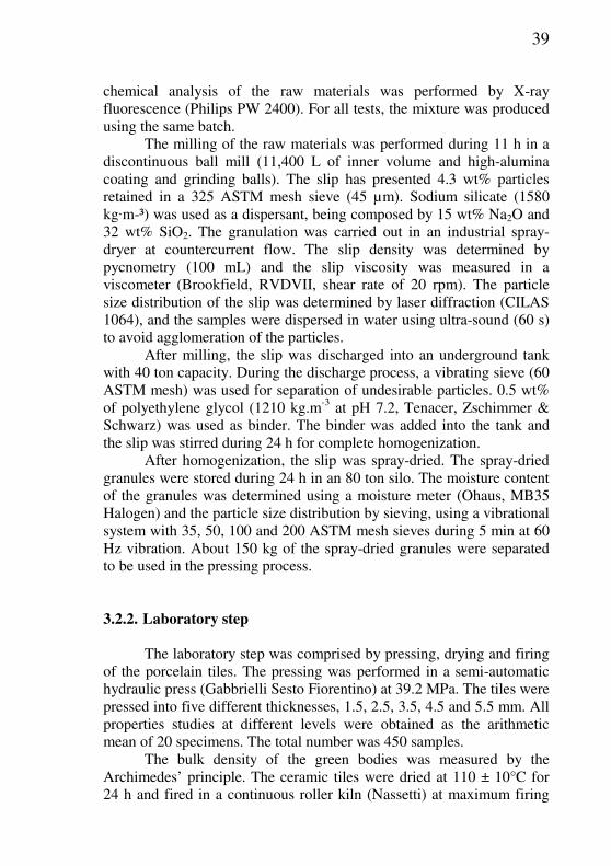
3.2.2. Laboratory step The laboratory step was comprised by pressing, drying and firing
of the porcelain tiles. The pressing was performed in a semi-automatic hydraulic press (Gabbrielli Sesto Fiorentino) at 39.2 MPa. The tiles were pressed into five different thicknesses, 1.5, 2.5, 3.5, 4.5 and 5.5 mm. All properties studies at different levels were obtained as the arithmetic mean of 20 specimens. The total number was 450 samples.
The bulk density of the green bodies was measured by the Archimedes’ principle. The ceramic tiles were dried at 110 ± 10°C for 24 h and fired in a continuous roller kiln (Nassetti) at maximum firing

40
temperatures of 1180, 1200 and 1220°C with heating and cooling rates of 40°C/min.
3.2.3. Characterization of fired tiles The linear shrinkage and the loss on ignition of the ceramic tiles
were determined after firing. The mechanical strength was determined by the three-loading method (Gabbrielli Sesto Fiorentino) according the ISO 10545-4 standard [30]. The water absorption was determined by the boiling water method according the ISO 10545-3 standard [31]. The microstructural analysis was performed on the fractured surface of the samples using a Scanning Electron Microscope (SEM, Philips XL30). The bulk density after firing was studied using the Archimedes’ principle. All results were studied using analysis of variance (ANOVA [32]).
3.3. RESULTS AND DISCUSSION
3.3.1. Characterization of the ceramic batch
Table 3.1 shows the composition of the formulation and the
chemical analysis of the raw materials used in the porcelain tile batch. Feldspar A shows a little amount of Fe2O3 and TiO2, resulting in a white color after firing. The Na2O content reduces the firing temperature acting as a flux. Clay A shows a higher amount of Fe2O3 and therefore a darker color. The high Al2O3 content results in a higher firing temperature. Clay B is basically composed by silica and alumina, being complementary in the formulation of the ceramic batch. Talc is used in the formulation to reduce the viscosity of the liquid phase formed during firing. Finally, the kaolin presents K2O and Na2O reducing the refractoriness.
41
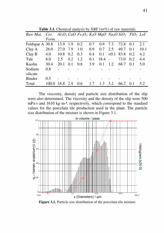
Table 3.1. Chemical analysis by XRF (wt%) of raw materials.
Raw Mat. Cer.
Form.
Al2O3 CaO Fe2O3 K2O MgO Na2O SiO2 TiO2 LoI
Feldspar A 30.8 13.9 1.9 0.2 0.7 0.9 7.3 72.8 0.1 2.1 Clay A 26.0 27.0 7.9 1.0 0.9 0.7 2.5 49.7 0.1 10.1 Clay B 4.0 10.8 0.2 0.3 0.4 0.1 <0.1 83.8 0.2 4.2 Talc 8.0 2.5 0.2 1.2 0.1 18.4 - 73.0 0.2 4.4 Kaolin 30.4 20.1 0.1 0.8 3.9 0.1 1.2 68.7 0.1 5.0 Sodium silicate
0.8 - - - - - - - - -
Binder 0.5 - - - - - - - - - Total 100.0 18.8 2.9 0.6 1.7 1.3 3.2 66.2 0.1 5.2
The viscosity, density and particle size distribution of the slip
were also determined. The viscosity and the density of the slip were 500 mPa·s and 1610 kg·m-³, respectively, which correspond to the standard values for the porcelain tile production used in the plant. The particle size distribution of the mixture is shown in Figure 3.1.
Figure 3.1. Particle size distribution of the porcelain tile mixture.

42
The moisture content of the spray-dried batch was 6.2 wt% and the compaction pressure was 39.2 MPa. The same moisture content and compaction pressure were used during all the experiment in order to minimize variations in the bulk density. The size distribution of the spray-dried granules used in the study is shown in Table 3.2. The weight percentages refer to the fraction of the granules retained in the sieves.
Table 3.2. Size distribution of the spray-dried granules.
Sieve ASTM mesh
(µm)
#35
(500)
#50
(297)
#100
(149)
#200
(74)
<74
µm
Retained (wt %) 39.7 50.7 7.9 0.7 0.4 A suitable packaging during pressing is the result of a smooth
flow and an adequate size distribution of the ceramic granules. Spray-dried granules smaller than 125 µm present less fluidity during pressing. Powders with higher fluidity are those in the range of 125 to 500 µm [33]. In this way, granule size distribution found in Table 3.2 is suitable to high fluidity.
3.3.2. Characterization of the porcelain tiles
The bulk density (green and fired), firing shrinkage, loss on
ignition, mechanical strength, water absorption and microstructure of the compacts were studied. All results were analyzed using ANOVA with p<0.05.
3.3.2.1. Bulk density The bulk density of the specimens is shown in Table 3.3. The
density of the ceramic tiles remained statistically unchanged when their thickness was changed. The pressing pressure and the moisture content of the ceramic powder were constant during the experiments. The ANOVA of the experiment showed no significant differences in density as a function of thickness.
Table 3.3. Bulk density of the tiles according to the thickness.
Thickness (mm) 1.5 2.5 3.5 4.5 5.5
Bulk density (kg·m-3) 1959 1980 1968 1958 1970 Standard deviation (%) 2.1 1.3 1.4 1.1 0.6
43
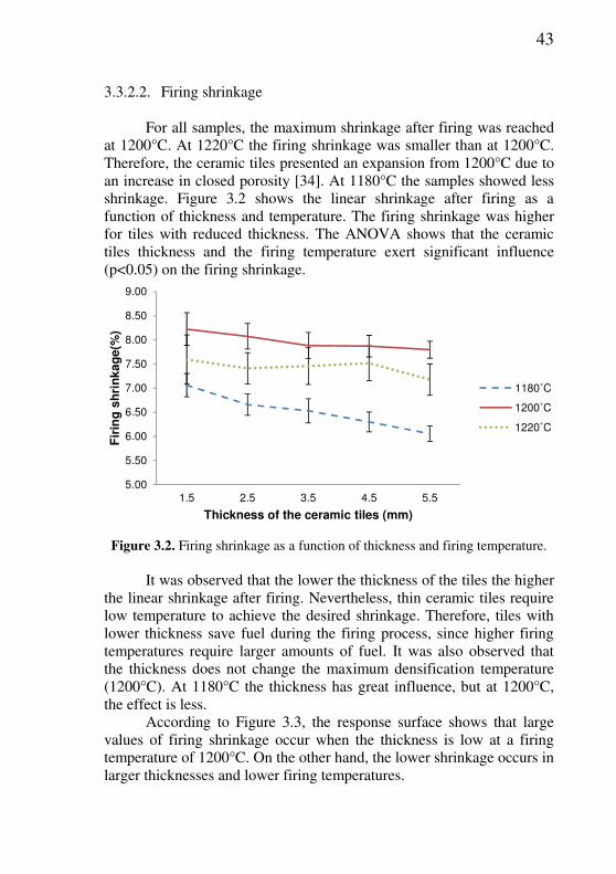
3.3.2.2. Firing shrinkage For all samples, the maximum shrinkage after firing was reached
at 1200°C. At 1220°C the firing shrinkage was smaller than at 1200°C. Therefore, the ceramic tiles presented an expansion from 1200°C due to an increase in closed porosity [34]. At 1180°C the samples showed less shrinkage. Figure 3.2 shows the linear shrinkage after firing as a function of thickness and temperature. The firing shrinkage was higher for tiles with reduced thickness. The ANOVA shows that the ceramic tiles thickness and the firing temperature exert significant influence (p<0.05) on the firing shrinkage.
5.00
5.50
6.00
6.50
7.00
7.50
8.00
8.50
9.00
1.5 2.5 3.5 4.5 5.5
Fir
ing
sh
rin
ka
ge
(%)
Thickness of the ceramic tiles (mm)
1180˚C
1200˚C
1220˚C
Figure 3.2. Firing shrinkage as a function of thickness and firing temperature.
It was observed that the lower the thickness of the tiles the higher
the linear shrinkage after firing. Nevertheless, thin ceramic tiles require low temperature to achieve the desired shrinkage. Therefore, tiles with lower thickness save fuel during the firing process, since higher firing temperatures require larger amounts of fuel. It was also observed that the thickness does not change the maximum densification temperature (1200°C). At 1180°C the thickness has great influence, but at 1200°C, the effect is less.
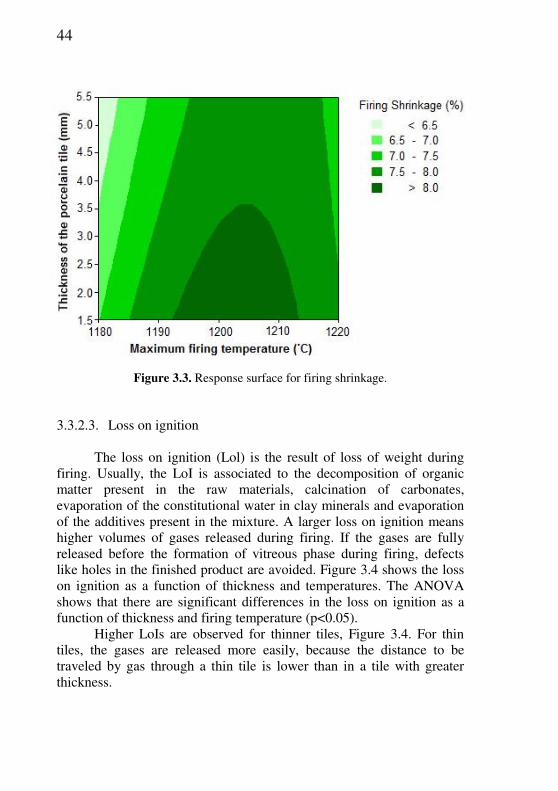
According to Figure 3.3, the response surface shows that large values of firing shrinkage occur when the thickness is low at a firing temperature of 1200°C. On the other hand, the lower shrinkage occurs in larger thicknesses and lower firing temperatures.
44
Figure 3.3. Response surface for firing shrinkage.
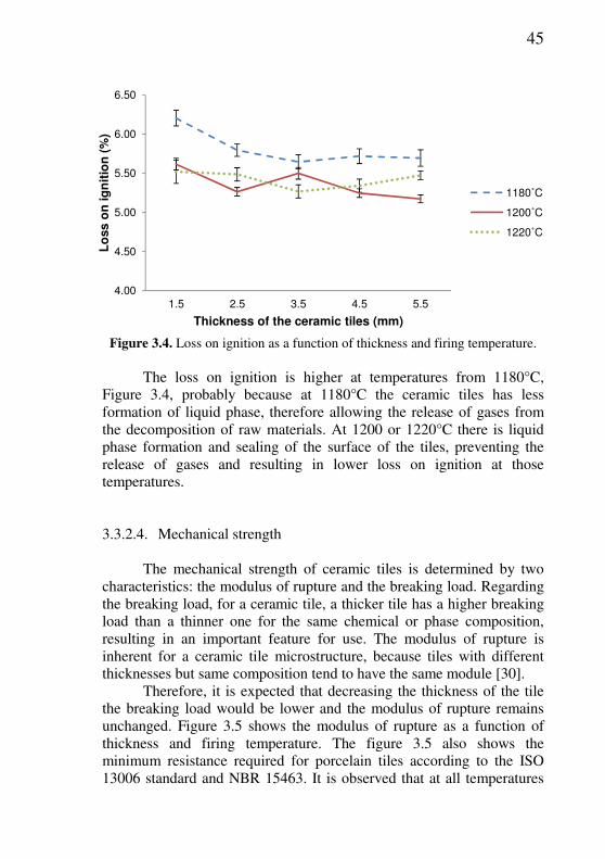
3.3.2.3. Loss on ignition The loss on ignition (Lol) is the result of loss of weight during
firing. Usually, the LoI is associated to the decomposition of organic matter present in the raw materials, calcination of carbonates, evaporation of the constitutional water in clay minerals and evaporation of the additives present in the mixture. A larger loss on ignition means higher volumes of gases released during firing. If the gases are fully released before the formation of vitreous phase during firing, defects like holes in the finished product are avoided. Figure 3.4 shows the loss on ignition as a function of thickness and temperatures. The ANOVA shows that there are significant differences in the loss on ignition as a function of thickness and firing temperature (p<0.05).
Higher LoIs are observed for thinner tiles, Figure 3.4. For thin tiles, the gases are released more easily, because the distance to be traveled by gas through a thin tile is lower than in a tile with greater thickness.
45
4.00
4.50
5.00
5.50
6.00
6.50
1.5 2.5 3.5 4.5 5.5
Lo
ss
on
ig
nit
ion
(%
)
Thickness of the ceramic tiles (mm)
1180˚C
1200˚C
1220˚C
Figure 3.4. Loss on ignition as a function of thickness and firing temperature.
The loss on ignition is higher at temperatures from 1180°C,
Figure 3.4, probably because at 1180°C the ceramic tiles has less formation of liquid phase, therefore allowing the release of gases from the decomposition of raw materials. At 1200 or 1220°C there is liquid phase formation and sealing of the surface of the tiles, preventing the release of gases and resulting in lower loss on ignition at those temperatures.
3.3.2.4. Mechanical strength The mechanical strength of ceramic tiles is determined by two
characteristics: the modulus of rupture and the breaking load. Regarding the breaking load, for a ceramic tile, a thicker tile has a higher breaking load than a thinner one for the same chemical or phase composition, resulting in an important feature for use. The modulus of rupture is inherent for a ceramic tile microstructure, because tiles with different thicknesses but same composition tend to have the same module [30].
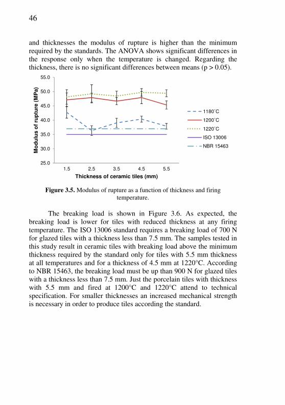
Therefore, it is expected that decreasing the thickness of the tile the breaking load would be lower and the modulus of rupture remains unchanged. Figure 3.5 shows the modulus of rupture as a function of thickness and firing temperature. The figure 3.5 also shows the minimum resistance required for porcelain tiles according to the ISO 13006 standard and NBR 15463. It is observed that at all temperatures
46
and thicknesses the modulus of rupture is higher than the minimum required by the standards. The ANOVA shows significant differences in the response only when the temperature is changed. Regarding the thickness, there is no significant differences between means (p > 0.05).
25.0
30.0
35.0
40.0
45.0
50.0
55.0
1.5 2.5 3.5 4.5 5.5
Mo
du
lus
of
rup
ture
(M
Pa)
Thickness of ceramic tiles (mm)
1180˚C
1200˚C
1220˚C
ISO 13006
NBR 15463
Figure 3.5. Modulus of rupture as a function of thickness and firing
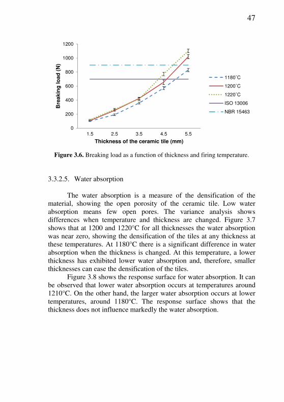
temperature. The breaking load is shown in Figure 3.6. As expected, the
breaking load is lower for tiles with reduced thickness at any firing temperature. The ISO 13006 standard requires a breaking load of 700 N for glazed tiles with a thickness less than 7.5 mm. The samples tested in this study result in ceramic tiles with breaking load above the minimum thickness required by the standard only for tiles with 5.5 mm thickness at all temperatures and for a thickness of 4.5 mm at 1220°C. According to NBR 15463, the breaking load must be up than 900 N for glazed tiles with a thickness less than 7.5 mm. Just the porcelain tiles with thickness with 5.5 mm and fired at 1200°C and 1220°C attend to technical specification. For smaller thicknesses an increased mechanical strength is necessary in order to produce tiles according the standard.
47
0
200
400
600
800
1000
1200
1.5 2.5 3.5 4.5 5.5
Bre
ak
ing
lo
ad
(N
)
Thickness of the ceramic tile (mm)
1180˚C
1200˚C
1220˚C
ISO 13006
NBR 15463
Figure 3.6. Breaking load as a function of thickness and firing temperature.
3.3.2.5. Water absorption The water absorption is a measure of the densification of the
material, showing the open porosity of the ceramic tile. Low water absorption means few open pores. The variance analysis shows differences when temperature and thickness are changed. Figure 3.7 shows that at 1200 and 1220°C for all thicknesses the water absorption was near zero, showing the densification of the tiles at any thickness at these temperatures. At 1180°C there is a significant difference in water absorption when the thickness is changed. At this temperature, a lower thickness has exhibited lower water absorption and, therefore, smaller thicknesses can ease the densification of the tiles.
Figure 3.8 shows the response surface for water absorption. It can be observed that lower water absorption occurs at temperatures around 1210°C. On the other hand, the larger water absorption occurs at lower temperatures, around 1180°C. The response surface shows that the thickness does not influence markedly the water absorption.

48
0.00
1.00
2.00
3.00
4.00
5.00
6.00
1.5 2.5 3.5 4.5 5.5
Wate
r ab
so
rpti
on
(%
)
Thickness of the ceramic tiles (mm)
1180˚C
1200˚C
1220˚C
Figure 3.7. Water absorption as a function of thickness and firing temperature.
Figure 3.8. Response surface for water absorption.
49
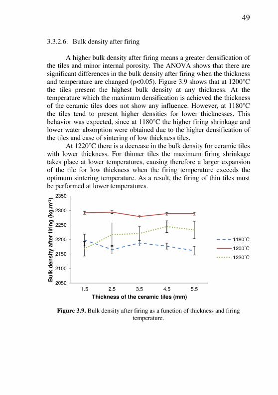
3.3.2.6. Bulk density after firing A higher bulk density after firing means a greater densification of
the tiles and minor internal porosity. The ANOVA shows that there are significant differences in the bulk density after firing when the thickness and temperature are changed (p<0.05). Figure 3.9 shows that at 1200°C the tiles present the highest bulk density at any thickness. At the temperature which the maximum densification is achieved the thickness of the ceramic tiles does not show any influence. However, at 1180°C the tiles tend to present higher densities for lower thicknesses. This behavior was expected, since at 1180°C the higher firing shrinkage and lower water absorption were obtained due to the higher densification of the tiles and ease of sintering of low thickness tiles.
At 1220°C there is a decrease in the bulk density for ceramic tiles with lower thickness. For thinner tiles the maximum firing shrinkage takes place at lower temperatures, causing therefore a larger expansion of the tile for low thickness when the firing temperature exceeds the optimum sintering temperature. As a result, the firing of thin tiles must be performed at lower temperatures.
2050
2100
2150
2200
2250
2300
2350
1.5 2.5 3.5 4.5 5.5
Bu
lk d
en
sit
y a
fte
r fi
rin
g (
kg
.m-3
)
Thickness of the ceramic tiles (mm)
1180˚C
1200˚C
1220˚C
Figure 3.9. Bulk density after firing as a function of thickness and firing
temperature.
50
3.3.2.7. Microstructure The microstructural analysis, Figure 3.10, was made for samples
pressed at two thicknesses (1.5 mm and 5.5 mm) and fired at three temperatures (1180, 1200 and 1220°C). At 1200°C the samples for both thicknesses show less porosity in comparison to other samples, corresponding to a higher bulk density and lower water absorption of the fired samples. Moreover, at the same temperature the 1.5 mm sample appears to be more compact than the 5.5 mm sample, corresponding to a higher firing shrinkage for the lower thickness.
The samples fired at 1180°C do not show significant differences regarding the thicknesses. However, the samples fired at 1220°C show larger pores for the 1.5 mm thickness samples regarding the 5.5 mm thickness samples. The expansion caused by the release of gases is increased in small thickness samples, since the sintering occurs at lower temperature. This is shown by the low apparent density at 1220°C for small thicknesses, resulting in higher pores, because the firing temperature was above the vitrification range, forcing the expulsion of the entrapped gases, resulting in blisters and bloating [34].

51
Figure 3.10. Microstructure of the porcelain tiles in two thicknesses and three temperatures.
1.5 mm 1180°C
1.5 mm 1200°C
1.5 mm 1220°C
5.5 mm 1180°C
5.5 mm 1200°C
5.5 mm 1220°C
52
3.4. CONCLUSIONS The results obtained in this study showed that the maximum
firing temperature and the thickness of the porcelain tiles resulted in significant differences in the microstructure and physical properties of the tiles.
The maximum firing shrinkage and the loss on ignition increase as the thickness of the tile is diminished. The module of rupture remains unchanged in relation to the thickness and the breaking load decreases as the thickness decreases. The water absorption is lower in thin ceramic tiles when fired at lower temperatures such as 1180°C and there are no significant differences at higher temperatures such as 1200 and 1220°C. The bulk density after firing is higher at 1200°C and did not show significant differences for all thicknesses of the fired tiles. At 1180°C the bulk density is higher for thin tiles but the density is lower compared with the tiles fired at 1200°C. At 1220°C the bulk density increases with the thickness of the tiles but is smaller in comparison with tiles fired at 1200°C due to the release of gases and expansion of the tiles.
Finally, the maximum firing temperature shows significant differences in the microstructure of the porcelain tiles. The better densification for the studied formulation was achieved at 1200°C.
3.5. REFERENCES
[1] ZANELLI, C. et al. Porcelain stoneware large slabs: processing and technological properties. Proc. Qualicer, p.1-9, 2010.
[2] MARTÍN-MÁRQUEZ, J.M.; RINCÓN, J.M.; Romero, M. Effect of microstructure on mechanical properties of porcelain stoneware. J. Eur.
Ceram. Soc., v.30, p.3063-3069, 2010.
[3] SÁNCHEZ, E. et al. Porcelain tile: Almost 30 years of steady scientific-technological evolution. Ceram. Int., v.36, p.831-845, 2010.
[4] AMORÓS, J.L. et al. Effect of the green porous texture on porcelain tile properties. J. Eur. Ceram. Soc., v.27, p.2295-2301, 2007.
[5] ISO 13006, Ceramic Tiles: Definitions, Classification, Characteristics and Marking, International Organization for Standardization, 1998.

53
[6] CARBONCHI, C.; REGINELLI, M. Analysis of low-thickness porcelain tile body. Ceram. World Rev., v.94, p.66-72, 2011.
[7] GOZZI, A. et al. Technological Behaviour of Low-thickness Ceramic Tile. Ceram. World Rev., v.83, p.78-80, 2009.
[8] RAIMONDO, M. et al. Processing and properties of large-sized ceramic slabs. Bol. Soc. Esp. Ceram.Vidrio, v.49, p.289-295, 2010.
[9] MORENO, A. Ceramic tiles: above and beyond traditional applications. J. Eur. Ceram. Soc., v.27, p.1607, 2007.
[10] IENCINELLA, D.; CENTURIONI, E.; BUSANA, M.G. Thin-film solar cells on commercial ceramic tiles. Solar Energy Mat. Solar Cells, v.93, p.206-210, 2009.
[11] GARCIA-TEN, J. et al. Development of light weight porcelain stoneware tiles using foaming agents. J. Eur. Ceram. Soc., v.32, p.745-752, 2012.
[12] RUSSO, M. Technical change and the industrial district: The role of inter firm relations in the growth and transformation of ceramic tile production in Italy. Res. Policy, v.14, p.329-343, 1985.
[13] SPINELLI, B. Technological solutions for the production of low-thickness tiles. Ceram. World Rev., v.83, p.76-77, 2009.
[14] LEONELLI, C. et al. Enhancing the mechanical properties of porcelain stoneware tiles: a microstructural approach. J. Eur. Ceram. Soc., v.21, p.785-793, 2001.
[15] BRAGANÇA, S.R.; BERGMANN C.P.; HÜBNER, H. Effect of quartz particle size on the strength of triaxial porcelain. J. Eur. Ceram.
Soc., v.26, p.3761-3761, 2006.
[16] ROMERO, M.; MARTÍN, J.M.; RINCÓN, J.M. Kinetic of mullite formation from a porcelain stoneware body for tiles production. J. Eur.
Ceram. Soc., v.26, p.1647-1647, 2006.
[17] CORREIA, S.L. et al. Properties of triaxial porcelain bodies: Interpretation of statistical modeling. J. Eur. Ceram. Soc., v.89, p.3356-3365, 2006.
[18] TUCCI, A. et al. New body mixes for porcelain stoneware tiles with improved mechanical characteristics. J. Eur. Ceram. Soc., v.27, p.1875-1881, 2007.
54
[19] CARBAJAL, L. et al. Properties related phase evolution in porcelain ceramics. J. Eur. Ceram. Soc., v.27, p.4065-4069, 2007.
[20] DE NONI, A.J. et al. Influence of post-fire cooling on porcelain tile mechanical properties. Bol. Soc. Esp. Ceram. Vidrio, v.46, p.163-170, 2007.
[21] MARTIN, J.M.; RINCON, J.M.; ROMERO, M. Effect of firing temperature on sintering of porcelain stoneware tiles. Ceram. Int., v.34, p.1867-1873, 2008.
[22] DE NONI, A.J. et al. Influence of macroscopic residual stresses on the mechanical behavior and microstructure of porcelain tile. J. Eur.
Ceram. Soc., v.28, p.2463-2469, 2008.
[23] DE NONI, A.J. et al. Analysis of the development of microscopic residual stresses on quartz particles in porcelain tile. J. Eur. Ceram.
Soc., v.28, p.2629-2637, 2008.
[24] CORREIA, S.L.; HOTZA, D.; SEGADAES, A.M. Predicting porosity content in triaxial porcelain bodies as a function of raw materials contents. J. Mat. Sci., v.43, p.696-701, 2008.
[25] DE NONI, A.J. et al. Effect of quartz particle size on the mechanical behaviour of porcelain tile subjected to different cooling rates. J. Eur. Ceram. Soc., v.29, p.1039-1046, 2009.
[26] DE NONI, A.J. et al. Influence of composition on mechanical behaviour of porcelain tile. Part I: Microstructural characterization and developed phases after firing. Mat. Sci. Eng.,v.527, p.1730-1735, 2010.
[27] DE NONI, A.J. et al. Influence of composition on mechanical behaviour of porcelain tile. Part II: Mechanical properties and microscopic residual stress. Mat. Sci. Eng., v.527, p.1736-1743, 2010.
[28] DE NONI, A.J. et al. Influence of composition on mechanical behaviour of porcelain tile. Part III: Effect of the cooling rate of the firing cycle. Mat. Sci. Eng., v.528, p.3330-3336, 2011.
[29] DAL BO, M. et al. Mechanical modelling of rapid cooling in porcelain tile-type systems. Bol. Soc. Esp. Ceram. Vidrio., v.51, p.95-102, 2012.
[30] ISO 10545-4: Ceramic Tiles – Part 4: Determination of modulus of rupture and breaking strength, 2.ed., 2004.
55
[31] ISO 10545-3: Ceramic Tiles – Part 3: Determination of water absorption, apparent porosity, apparent relative density and bulk density, 1995.
[32] MONTGOMERY, D.C.; RUNGER, G.C. Applied Statistics and
Probability for Engineers. New York: Wiley, 2002.
[33] EMILIANI, G.P.; CORBARA, F. Tecnologia cerâmica. Faenza: Faenza Editrice, 2001.
[34] MARTÍN, J.M.; RINCÓN, J.M.; ROMERO, M. Effect of firing temperature on sintering of porcelain stoneware tiles. Ceram. Int., v.34, p.1867-1873, 2008.

56
4. EFFECT OF PRESSING PARAMETERS AND FIRING TEMPERATURE ON MICROSTRUCTURE AND PHYSICAL PROPERTIES OF THIN PORCELAIN TILES
4.1. INTRODUCTION
Porcelain tile is a ceramic product that shows high mechanical strength and remarkable frost, stain, and chemical resistance. These features are closely related to the porous microstructure of the fired tile [1], which stems from the evolution of the green tile microstructure during heat treatment [2-3]. As temperature rises, liquid-phase formation (beginning at about 900˚C) increases, bringing the particles closer together, lowering total porosity, and altering pore size and shape. Sufficiently high temperatures (above 1180˚C) close the pores and reduce apparent porosity. However, excessively high temperatures raise the gas pressure in the closed pores above the capillary pressure, which leads to bloating [4].
The industrial processing of porcelain tile includes three main stages: (1) wet milling and homogenization of raw materials, followed by spray-drying of the resulting suspension; (2) uniaxial pressing at 35-45 MPa of the spray-dried powder with a moisture content of 5-7%; (3) fast firing for 40-60 min at 1180-1220˚C to obtain maximum densification [1]. All stages are important, but in this work the pressing and firing steps of porcelain tiles with reduced thickness were studied.
Pressing is a very widely used process for forming ceramics. It is suitable for both fine and coarse grained ceramics [5]. The dry pressing in a continuous production consists of a series of operations which are repeated in the following order: loading of powder in the mold, pre-compaction in order to expel the air incorporated in the powder interstices, pressing, and extraction of the product pressed from the mold [6].
Compression increases the compactness of the material, which manifests itself in an increase in the bulk density of formed product, caused by the presence of clay components in the body and aided by the water content to which these components owe their plasticity [7]. Industrial pressing machines usually offer some options which are thought to improve the green sample characteristics. For example, the overall density may be increased by the application of a second pressure cycle [8]. ________________________ 2 A ser submetido para publicação.
57
Sintering is the process by which a powder compact is transformed to a strong, dense ceramic body upon heating. It can occur in the presence or absence of a liquid phase. In the former case, it is called liquid-phase sintering, where the compositions and firing temperatures are chosen such that some liquid is formed during processing [9].
The search for new applications of the porcelain tiles has not only required investigation of new installation systems but the design of new products, such as porcelain tile laminates, which may be up to 4 m long and just 3 mm thick [10]. This innovation focused initially almost exclusively on new applications of porcelain tiles, differing from current uses, aimed at replacing materials such as wood, plastic, or metal in applications till now inaccessible to ceramics, such as armored doors or kitchen shelves, since the possible tile sizes that can be made are practically unlimited [1].
The reduction of thickness is an important technological innovation aimed at lowering both the production costs per unit surface area and the costs of packaging and transport. Furthermore, saving raw materials represents an environmental gain [11-12]. However, the studies published about reduced thickness tiles [10-12] do not show the processing parameters influences on the microstructure and physical characteristics of the porcelain tiles.
Therefore, the objective of this work was the study of the influence of the pressing pressure, pressing cycle, and firing temperature on the properties and microstructure of thin porcelain tiles.
4.2. EXPERIMENTAL PROCEDURE
4.2.1. Industrial step The industrial step is the ceramic tile batch preparation (milling
and spray drying). An industrial porcelain tile batch was used, composed by two clays, feldspar, kaolin and talc. The chemical analysis of the raw materials was determined by X-ray fluorescence (Philips PW 2400). For all tests and characterizations, the ceramic batch was produced using the same batch. The milling of the raw materials was performed during 11 h in a discontinuous ball mill (11,400 L inner volume and high-alumina coating and grinding balls). The slip presented 4.3 wt% of the particles retained in a 325 ASTM mesh sieve. Sodium silicate (1580 kg.m-³) was used as a dispersant, being composed by 15 wt% Na2O and 32 wt%

58
SiO2. The spray-drying was carried out in an industrial spray-dryer at countercurrent flow. The density of the slip was determined by pycnometry (100 mL) and the rheological behavior by a viscometer (Brookfield RVDVII, shear rate of 20 rpm). The particle size distribution of the slip was determined by laser diffraction (CILAS model 1064) and the sample was dispersed in water using ultra-sound (60 s) to avoid agglomeration of the particles.
After milling, the slip was discharged into an underground tank with 40 ton capacity. During the discharge process, a vibrating sieve (60 ASTM mesh) was used for separation of undesirable particles. An additive, 0.5 wt% polyethylene glycol (Tenacer, Zschimmer & Schwarz,), 1210 kg·m-3 of density and pH 7.2, was added in the tank and the slip was stirred during 24 h for complete homogenization. After homogenization, the slip was spray-dried. The spray-dried granules were stored during 24 h in an 80 ton silo. The moisture content of the powder was determined using a moisture meter (Ohaus, MB35 Halogen, Canada) and the particle size distribution by sieving, using a vibrational system with 35, 50, 100 and 200 ASTM mesh sieves during 5 min at 60 Hz vibration. About 150 kg of the spray-dried powder were separated to be used in the pressing process.
4.2.2. Laboratory step In the laboratory step the pressing, drying and firing of the
ceramic tiles were performed. The pressing was performed in a semi-automatic hydraulic press (Gabbrielli Sesto Fiorentino). All tiles were conformed to 2.5 mm thickness, characterizing a thin ceramic tile in comparison with the regular thickness of 5-7 mm. The sizes of specimens were 30 x 100 mm. Two pressing pressures (39.2 and 58.8 MPa) and two pressing cycles were used (Figure 4.1): a) cycle one: first pressing until 8.8 MPa, relief and second pressing until 58.8 MPa, with a total time of 5 s; b) cycle two: first pressing until 8.8 MPa, relief and second pressing pressure gradually increased up to 58.8 MPa, with a total cycle time of 60 s.
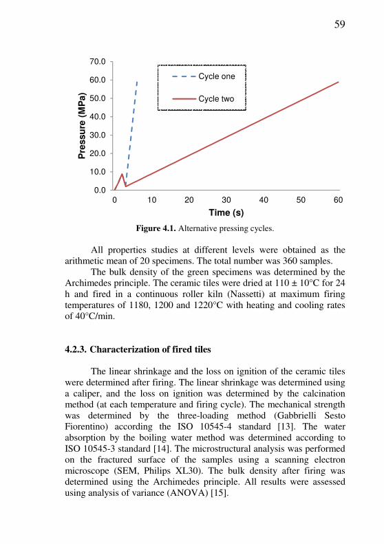
59
0.0
10.0
20.0
30.0
40.0
50.0
60.0
70.0
0 10 20 30 40 50 60
Pre
ssu
re (
MP
a)
Time (s)
Cycle one
Cycle two
Figure 4.1. Alternative pressing cycles.
All properties studies at different levels were obtained as the
arithmetic mean of 20 specimens. The total number was 360 samples. The bulk density of the green specimens was determined by the
Archimedes principle. The ceramic tiles were dried at 110 ± 10°C for 24 h and fired in a continuous roller kiln (Nassetti) at maximum firing temperatures of 1180, 1200 and 1220°C with heating and cooling rates of 40°C/min.
4.2.3. Characterization of fired tiles The linear shrinkage and the loss on ignition of the ceramic tiles
were determined after firing. The linear shrinkage was determined using a caliper, and the loss on ignition was determined by the calcination method (at each temperature and firing cycle). The mechanical strength was determined by the three-loading method (Gabbrielli Sesto Fiorentino) according the ISO 10545-4 standard [13]. The water absorption by the boiling water method was determined according to ISO 10545-3 standard [14]. The microstructural analysis was performed on the fractured surface of the samples using a scanning electron microscope (SEM, Philips XL30). The bulk density after firing was determined using the Archimedes principle. All results were assessed using analysis of variance (ANOVA) [15].
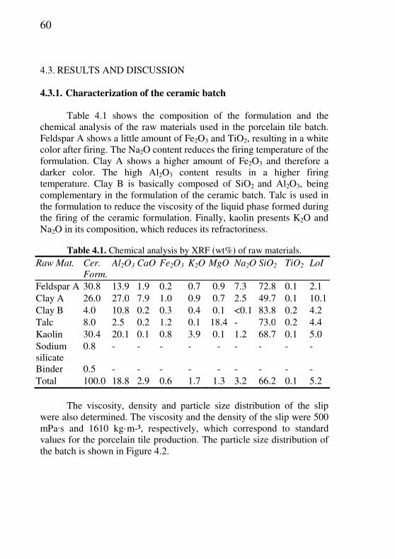
60
4.3. RESULTS AND DISCUSSION
4.3.1. Characterization of the ceramic batch
Table 4.1 shows the composition of the formulation and the
chemical analysis of the raw materials used in the porcelain tile batch. Feldspar A shows a little amount of Fe2O3 and TiO2, resulting in a white color after firing. The Na2O content reduces the firing temperature of the formulation. Clay A shows a higher amount of Fe2O3 and therefore a darker color. The high Al2O3 content results in a higher firing temperature. Clay B is basically composed of SiO2 and Al2O3, being complementary in the formulation of the ceramic batch. Talc is used in the formulation to reduce the viscosity of the liquid phase formed during the firing of the ceramic formulation. Finally, kaolin presents K2O and Na2O in its composition, which reduces its refractoriness.
Table 4.1. Chemical analysis by XRF (wt%) of raw materials. Raw Mat. Cer.
Form.
Al2O3 CaO Fe2O3 K2O MgO Na2O SiO2 TiO2 LoI
Feldspar A 30.8 13.9 1.9 0.2 0.7 0.9 7.3 72.8 0.1 2.1 Clay A 26.0 27.0 7.9 1.0 0.9 0.7 2.5 49.7 0.1 10.1 Clay B 4.0 10.8 0.2 0.3 0.4 0.1 <0.1 83.8 0.2 4.2 Talc 8.0 2.5 0.2 1.2 0.1 18.4 - 73.0 0.2 4.4 Kaolin 30.4 20.1 0.1 0.8 3.9 0.1 1.2 68.7 0.1 5.0 Sodium silicate
0.8 - - - - - - - - -
Binder 0.5 - - - - - - - - - Total 100.0 18.8 2.9 0.6 1.7 1.3 3.2 66.2 0.1 5.2
The viscosity, density and particle size distribution of the slip
were also determined. The viscosity and the density of the slip were 500 mPa·s and 1610 kg·m-³, respectively, which correspond to standard values for the porcelain tile production. The particle size distribution of the batch is shown in Figure 4.2.

61
Figure 4.2. Particle size distribution of the porcelain tile powder batch.
The moisture content of the spray-dried batch was 6.2 wt%. The
size distribution of the spray-dried granules used in the study is shown in Table 4.2. The weight percentages refer to the fraction of the spray-dried powder retained in the sieves.
Table 4.2. Size distribution of the spray-dried granules. Sieve ASTM mesh
(µm)
#35
(500)
#50
(297)
#100
(149)
#200
(74)
<74
µm
Retained (wt %) 39.7 50.7 7.9 0.7 0.4
A suitable packaging during pressing is the result of a smooth flow and an adequate size distribution of the ceramic granules. Spray-dried granules lower than 125 µm have less fluidity; those granules as the ones used in this work in the range of 125 to 500 µm [16] flow better.

62
4.3.2. Characterization of the ceramic tiles The bulk density (green and fired), firing shrinkage, loss on
ignition, mechanical strength, water absorption and microstructure of the compacts were analyzed in this study and they are shown in the next sections.
4.3.2.1. Influence of the pressing pressure and firing temperature on physical properties
4.3.2.1.1. Bulk density
The bulk density of the samples is shown in Table 4.3. A higher
density was expected using higher pressing pressure. The ANOVA of the experiment (p<0.05) showed that significant differences in density were obtained as a function of pressing pressure.
Table 4.3. Bulk density of the tiles as a function of the pressing pressure.
Pressing pressure (MPa) 39.22 58.84
Bulk density (kg·m-3) 1980 2030 Standard deviation (%) 1.5 1.5
The initial volume of the compact is given by the sum of the
volume of the solid particles and the volume of the empty spaces between them. The empty spaces correspond to two types of pores that make up the microstructure of the green compact: intragranular pores (spaces between the particles that comprise the grain) and intergranular pores (set of voids that form during packing of the granules) [2,17]. As the bulk density of the compact is given by the ratio between the mass and volume thereof, and the mass remains constant during compression, the only way to increase the density is by reducing the volume. The intragranular pores are practically of the same particle size of the powder and are unlikely to suffer a significant reduction of their volume; therefore, with little influence on the density of the compact. As a result, the increase in density during compression is the result of plastic deformation of the granules, which when deformed can occupy the empty space between them (intergranular porosity). In cases where the granules are hollow, quite common feature in granulated powders produced by spray-drying, the filling of the hollow spaces is carried out

63
by the milled particles that form the granules. Therefore, densification depends on the ease that the granules deform plastically, i.e., their plasticity. When keeping constant the moisture of the granules, the bulk density increases with an increasing compaction pressure because the deformation of the granules increases thus reducing the empty spaces inside the compact [17-19].
4.3.2.1.2. Firing shrinkage The average firing shrinkage as a function of pressing pressure
and firing temperature is shown in Figure 4.3. The statistical analysis showed significant differences in firing shrinkage when the pressing pressure and firing temperature were changed (p<0.05).
4.00
4.50
5.00
5.50
6.00
6.50
7.00
7.50
8.00
8.50
9.00
1180 °C 1200 °C 1220 °C
Fir
ing
sh
rin
kag
e(%
)
Maximum temperature of firing (°C)
39.22 MPa
58.84 MPa
Figure 4.3. Firing shrinkage as a function of pressing pressure and firing
temperature. The highest firing shrinkage occurred at a pressing pressure of
39.2 MPa and firing temperature of 1200˚C. The samples pressed at 58.8 MPa showed less firing shrinkage at all temperatures.
An increase in the pressing pressure corresponds to a decrease in shrinkage along the subsequent phases of the tile processing (drying and firing). This is due to the fact that sintering at high temperature also leads to a reduction in the volume of the spaces between the particles of
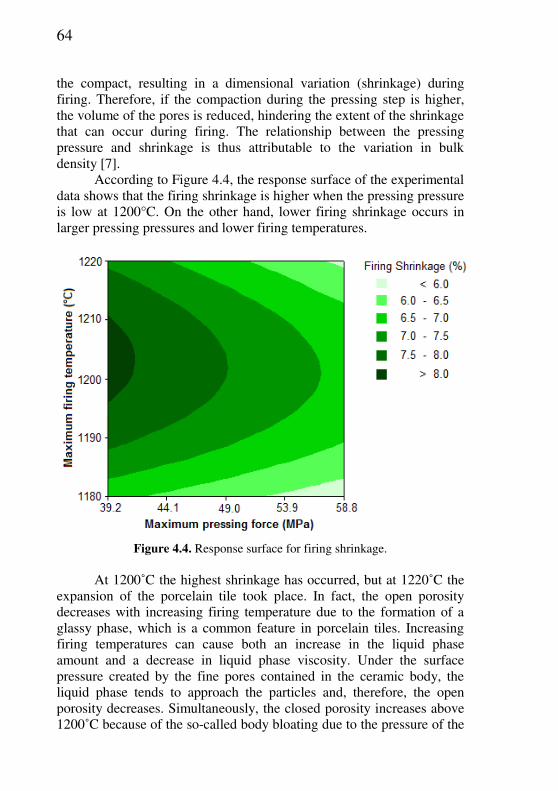
64
the compact, resulting in a dimensional variation (shrinkage) during firing. Therefore, if the compaction during the pressing step is higher, the volume of the pores is reduced, hindering the extent of the shrinkage that can occur during firing. The relationship between the pressing pressure and shrinkage is thus attributable to the variation in bulk density [7].
According to Figure 4.4, the response surface of the experimental data shows that the firing shrinkage is higher when the pressing pressure is low at 1200°C. On the other hand, lower firing shrinkage occurs in larger pressing pressures and lower firing temperatures.
Figure 4.4. Response surface for firing shrinkage.
At 1200˚C the highest shrinkage has occurred, but at 1220˚C the
expansion of the porcelain tile took place. In fact, the open porosity decreases with increasing firing temperature due to the formation of a glassy phase, which is a common feature in porcelain tiles. Increasing firing temperatures can cause both an increase in the liquid phase amount and a decrease in liquid phase viscosity. Under the surface pressure created by the fine pores contained in the ceramic body, the liquid phase tends to approach the particles and, therefore, the open porosity decreases. Simultaneously, the closed porosity increases above 1200˚C because of the so-called body bloating due to the pressure of the

65
gas inside the closed pores, which tends to expand the pores. This behavior is similar to that showed by almost all porcelain bodies [20].
4.3.2.1.3. Loss on ignition The loss on ignition (LoI) is the result of loss of weight during
firing. Usually, LoI is associated with the decomposition of organic matter present in the raw materials, decomposition of carbonates and evaporation of the constitution water of the minerals and additives present in the batch. A higher loss on ignition means higher volumes of gases released during firing. If the gases are fully released before the formation of the vitreous phase during firing, defects like holes in the finished product are avoided [21].
As the specific compacting pressure is increased, the pore size is reduced being difficult for gases to escape during firing. If the compact contains organic substances, this feature becomes apparent in the form of a dark stain inside the piece (known as “black core”), which may also be caused by other factors, but is almost always attributable to pressing. There is a specific pressure threshold value beyond which the negative effects of the black core start to become apparent during firing [7].
The average loss on ignition due to the pressing pressure and maximum firing temperature is shown in Figure 4.5. The analysis of variance with a confidence level of 95% (p<0.05) shows no significant variation in the loss on ignition as a function of the pressing pressure and firing temperature.

66
3.00
3.50
4.00
4.50
5.00
5.50
6.00
1180 °C 1200 °C 1220 °C
Lo
ss o
n ig
nit
ion
(%
)
Maximum temperature of firing (°C)
39.22 MPa
58.84 MPa
Figure 4.5. Loss on ignition as a function of pressing pressure and firing
temperature. The results of this study show that for thin ceramic tiles the
release of gas during firing is not dependent on the pressing pressure. Probably, for thin ceramic tiles the densification process during the pressing step did not influence the release of gases disregarding the pressing pressure used, because the distance traveled by gas in thin tiles is lower in comparison to thick ceramics.
4.3.2.1.4. Mechanical strength The mean mechanical strength as a function of pressing pressure
and firing temperature is shown in Figure 4.6.

67
25.00
30.00
35.00
40.00
45.00
50.00
55.00
60.00
1180 °C 1200 °C 1220 °C
Mo
du
lus
of
rup
ture
(M
Pa)
Maximum temperature of firing (°C)
39.22 MPa
58.84 MPa
Figure 4.6. Mechanical strength as a function of pressing pressure and firing
temperature. The statistical analysis (95% interval) showed that the firing
temperature significantly affects the mechanical strength. At 1180˚C the modulus of rupture was 36.1 and 36.8 MPa for pressing pressures of 39.2 MPa and 58.8 MPa, respectively. Between 1200 and 1220˚C the differences in mechanical strength between the tiles were minimal, thus justifying a temperature of 1200˚C for the production of ceramic tiles, because a lower firing temperature results in lower fuel consumption during firing.
The porosity has an effect on mechanical strength, attributed basically to the loss of resistant area resulting from the presence of pores [22]. However, the pressing pressure does not exert significant influence over the final mechanical strength of the thin porcelain tiles. The higher porosity of the porcelain tiles pressed at 39.2 MPa is offset by the higher firing shrinkage, resulting in ceramic tiles with similar porosities for both pressures used.
Figure 4.7 shows the response surface for the modulus of rupture. It can be observed that the pressing pressure has just a low influence on the mechanical strength. On the contrary, increasing firing temperatures result in higher values for the modulus of rupture. Observing the microstructure and bulk density after firing, for temperatures above 1200˚C there is a great amount of closed pores in the porcelain tiles. According to Martín-Márquez [23], the mechanical strength is not dependent on closed porosity but it is reliant on the open porosity of the

68
sample, which agrees with the present work. Probably if the pores were higher, the mechanical strength could be minor. But this did not occur in this work.
Figure 4.7. Response surface for modulus of rupture.
4.3.2.1.5. Water absorption The average water absorption as a function of pressing pressure
and firing temperature is shown in Figure 4.8.
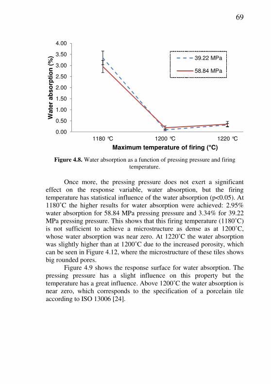
69
0.00
0.50
1.00
1.50
2.00
2.50
3.00
3.50
4.00
1180 °C 1200 °C 1220 °C
Wate
r ab
so
rpti
on
(%
)
Maximum temperature of firing (°C)
39.22 MPa
58.84 MPa
Figure 4.8. Water absorption as a function of pressing pressure and firing
temperature. Once more, the pressing pressure does not exert a significant
effect on the response variable, water absorption, but the firing temperature has statistical influence of the water absorption (p<0.05). At 1180˚C the higher results for water absorption were achieved: 2.95% water absorption for 58.84 MPa pressing pressure and 3.34% for 39.22 MPa pressing pressure. This shows that this firing temperature (1180˚C) is not sufficient to achieve a microstructure as dense as at 1200˚C, whose water absorption was near zero. At 1220˚C the water absorption was slightly higher than at 1200˚C due to the increased porosity, which can be seen in Figure 4.12, where the microstructure of these tiles shows big rounded pores.
Figure 4.9 shows the response surface for water absorption. The pressing pressure has a slight influence on this property but the temperature has a great influence. Above 1200˚C the water absorption is near zero, which corresponds to the specification of a porcelain tile according to ISO 13006 [24].
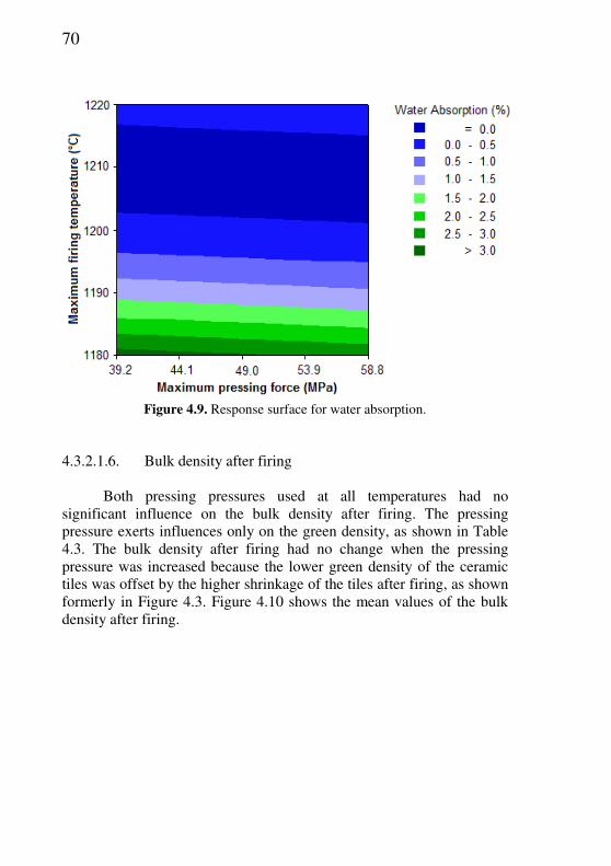
70
Figure 4.9. Response surface for water absorption.
4.3.2.1.6. Bulk density after firing
Both pressing pressures used at all temperatures had no
significant influence on the bulk density after firing. The pressing pressure exerts influences only on the green density, as shown in Table 4.3. The bulk density after firing had no change when the pressing pressure was increased because the lower green density of the ceramic tiles was offset by the higher shrinkage of the tiles after firing, as shown formerly in Figure 4.3. Figure 4.10 shows the mean values of the bulk density after firing.
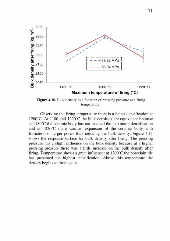
71
2050
2100
2150
2200
2250
2300
2350
1180 °C 1200 °C 1220 °CBu
lk d
en
sit
y a
fter
firi
ng
(kg
.m-3
)
Maximum temperature of firing (°C)
39.22 MPa
58.84 MPa
Figure 4.10. Bulk density as a function of pressing pressure and firing
temperature. Observing the firing temperature there is a better densification at
1200˚C. At 1180 and 1220˚C the bulk densities are equivalent because at 1180˚C the ceramic body has not reached the maximum densification and at 1220˚C there was an expansion of the ceramic body with formation of larger pores, thus reducing the bulk density. Figure 4.11 shows the response surface for bulk density after firing. The pressing pressure has a slight influence on the bulk density because at a higher pressing pressure there was a little increase on the bulk density after firing. Temperature shows a great influence: at 1200˚C the porcelain tile has presented the highest densification. Above this temperature the density begins to drop again.
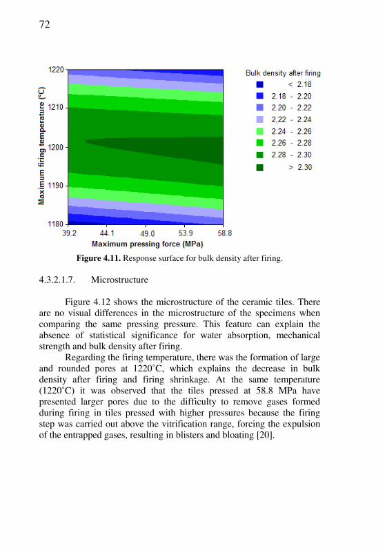
72
Figure 4.11. Response surface for bulk density after firing.
4.3.2.1.7. Microstructure
Figure 4.12 shows the microstructure of the ceramic tiles. There
are no visual differences in the microstructure of the specimens when comparing the same pressing pressure. This feature can explain the absence of statistical significance for water absorption, mechanical strength and bulk density after firing.
Regarding the firing temperature, there was the formation of large and rounded pores at 1220˚C, which explains the decrease in bulk density after firing and firing shrinkage. At the same temperature (1220˚C) it was observed that the tiles pressed at 58.8 MPa have presented larger pores due to the difficulty to remove gases formed during firing in tiles pressed with higher pressures because the firing step was carried out above the vitrification range, forcing the expulsion of the entrapped gases, resulting in blisters and bloating [20].
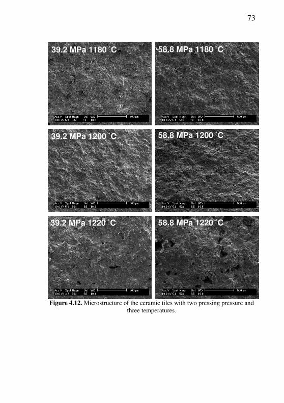
73
Figure 4.12. Microstructure of the ceramic tiles with two pressing pressure and three temperatures.
39.2 MPa 1180 ˚C
58.8 MPa 1220 ˚C
58.8 MPa 1200 ˚C
58.8 MPa 1180 ˚C
39.2 MPa 1220 ˚C
39.2 MPa 1200 ˚C

74
4.3.2.2. Influence of pressing cycle and firing temperature on the physical properties
Compaction tests were performed at different pressing cycles to
check if a gradual increase in the pressing pressure could improve the physical properties of the ceramic tiles. However, in all tests there were no significant differences in the response variables since the p-values in all tests were greater than 0.05. The bulk density (Table 4.4) has no significant differences between both cycles, indicating that the ceramic powder with the same moisture content and different pressing cycles shows the same bulk density after pressing and firing.
Table 4.4. Bulk density as a function of the pressing cycle. Cycle one Cycle two
Bulk density (kg·m-3) 2031 2038 Standard deviation (%) 1.43 1.58
The firing shrinkage is shown in Figure 4.13. There are
significant differences in the firing shrinkage only when the firing temperature is changed. The highest firing shrinkage has occurred at 1200˚C. At 1220˚C the firing shrinkage was smaller due to the increase in closed porosity caused by the increase on the gas pressure inside the closed pores.
The loss on ignition, shown in Figure 4.14, had no significant influence caused by the pressing cycle and firing temperature. Regarding the mechanical strength (Figure 4.15), the best results are obtained at 1200˚C. The lower water absorption (Figure 4.16) and higher bulk density after firing (Figure 4.17) were obtained also at 1200˚C and the different pressing cycles again had no significant influence.
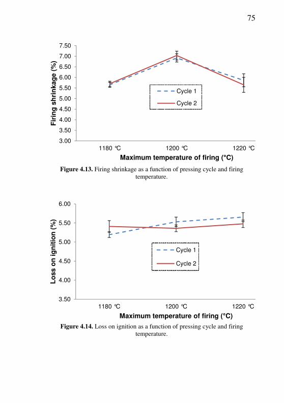
75
3.00
3.50
4.00
4.50
5.00
5.50
6.00
6.50
7.00
7.50
1180 °C 1200 °C 1220 °C
Fir
ing
sh
rin
kag
e (
%)
Maximum temperature of firing (°C)
Cycle 1
Cycle 2
Figure 4.13. Firing shrinkage as a function of pressing cycle and firing
temperature.
3.50
4.00
4.50
5.00
5.50
6.00
1180 °C 1200 °C 1220 °C
Lo
ss o
n ig
nit
ion
(%
)
Maximum temperature of firing (°C)
Cycle 1
Cycle 2
Figure 4.14. Loss on ignition as a function of pressing cycle and firing
temperature.

76
20.00
25.00
30.00
35.00
40.00
45.00
50.00
55.00
60.00
1180 °C 1200 °C 1220 °C
Mo
du
lus o
f ru
ptu
re (
MP
a)
Maximum temperature of firing (°C)
Cycle 1
Cycle 2
Figure 4.15. Modulus of rupture as a function of pressing cycle and firing
temperature.
0.00
0.50
1.00
1.50
2.00
2.50
3.00
3.50
1180 °C 1200 °C 1220 °C
Wate
r a
bso
rpti
on
(%
)
Maximum temperature of firing (°C)
Cycle 1
Cycle 2
Figure 4.16. Water absorption as a function of pressing cycle and firing
temperature.

77
2000
2050
2100
2150
2200
2250
2300
2350
1180 °C 1200 °C 1220 °C
Bu
lk d
en
sit
y a
fter
firi
ng
(K
g.c
m- ³
)
Maximum temperature of firing (°C)
Cycle 1
Cycle 2
Figure 4.17. Bulk density after firing as a function of pressing cycle and firing
temperature.
4.4. CONCLUSIONS The influence of the processing variables on the porcelain tiles
final properties plays an important role to control the production process. The results presented in this paper showed that the pressing pressure influences the bulk density and firing shrinkage. The higher the pressing pressure, the higher the bulk density and the firing shrinkage. In thin porcelain tiles formed with high pressing, as used in this work, the pressing pressure does not exert significant influence on the loss on ignition, mechanical strength, water absorption and bulk density after firing because the lower pressing pressure is compensated by the greater firing shrinkage, so the final porosity is almost the same. On the other hand, the maximum firing temperature exerts significant influence on the firing shrinkage, mechanical strength, water absorption and bulk density after firing.
The pressing cycle, i.e., the starting time of pressing until the maximum pressure is obtained has no effect on the physical properties of the ceramic tiles. In order to obtain improvements in the physical properties of ceramic tiles without changing the raw materials and/or powder processing, the best way is to study the influence of the firing process, because the pressing pressure and pressing cycle does not exert

78
influence on the mechanical strength, water absorption and bulk density after firing. On the other hand, when a greater dimensional stability of the product is needed it is advisable to use higher pressing pressures, since higher pressing pressures mean higher packing, resulting in less firing shrinkage, therefore the variation on the dimensions of the final product would be smaller if there were any abnormality in the processing of thin porcelain tiles.
4.5. REFERENCES
[1] SÁNCHEZ, E. et al. Porcelain tile: Almost 30 years of steady scientific-technological evolution. Ceram. Int., v.36, p.831-845, 2010. [2] ALVES, H.J.; MELCHIADES, F.G.; BOSCHI, A.O. Effect of spray-dried powder granulometry on the porous microstructure of polished porcelain tile. J. Eur. Ceram. Soc., v.30, p.1259-1266, 2010. [3] CAVALCANTE, P.M.T. et al. The influence of microstructure on the performance of white porcelain stoneware. Ceram. Int, v.30, p.953-963, 2004. [4] SHU, Z. et al. Cleaner production of porcelain tile powders. Fired compact properties. Ceram. Int., v.38, p.1479-1487, 2012. [5] KING, A.G. Ceramic technology and processing. Norwich, NY: Noyes, 2002. [6] EMILIANI, G.P.; CORBARA, F. Tecnologia ceramica: la lavorazione. v.2. Faenza: Faenza Editrice, 2002. [7] GUERRIERI, G. et al. Raw Material Preparation and Forming of Ceramic Tiles. ACIMAC: Associazione Costruttori Italiani Macchine Attrezzature per Ceramica., p.350-354, 2004. [8] TERPSTRA, R.A.; PEX, P.P.; VRIES, A.H. Ceramic Processing. London: Chapman & Hall, 1995. [9] BARSOUM, M.W. Fundamentals of Ceramics. New York: Taylor & Francis, 2003.

79
[10] VENTURELLI, M. The lamina revolution: an innovative, eco-friendly process. Ceram. World Rev., v.39, p.86-88, 2000. [11] CARBONCHI, C.; REGINELLI, M. Analysis of low-thickness porcelain tile body. Ceram. World Rev., v.94, p.66-72, 2011. [12] GOZZI, A. et al. Technological Behaviour of Low-thickness Ceramic Tile. Ceram. World Rev., v.83, p.78-80, 2009. [13] ISO 10545-4: Ceramic Tiles – Part 4: Determination of modulus of rupture and breaking strength, second edition, 2004. [14] ISO 10545-3: Ceramic Tiles – Part 3: Determination of water absorption, apparent porosity, apparent relative density and bulk density, 1995. [15] MONTGOMERY, D.C.; RUNGER, G.C. Applied Statistics and
Probability for Engineers. New York: Wiley, 2002. [16] EMILIANI, G.P.; CORBARA, F. Tecnologia cerâmica. 2.ed. Faenza: Faenza Editrice, 2001. [17] DE PAULA, G.R.; QUINTEIRO, E.; BOSCHI, A.O. Efeito do teor de umidade e da pressão de prensagem sobre as características de revestimentos cerâmicos. Cerâmica Industrial, São Paulo, v.2, n.3/4, p.28-31, maio/ago. 1997. [18] BOSCHI, A.O.; QUINTEIRO, E.; DE PAULA, G.R. The relationship between the characteristics of ceramic tiles, before and after firing, and the water content of granulated powder and the compactation pressure. Proc. Qualicer, p.79–81, 1998. [19] REED, J.S. Principles of ceramic processing. 2.ed. New York: Wiley, 1995. [20] MARTÍN, J.M.; RINCÓN, J.M.; ROMERO, M. Effect of firing temperature on sintering of porcelain stoneware tiles. Ceram. Int., v.34, p.1867-1873, 2008. [21] ALBERO, J.L.A. et al. Defectos de Fabricación de Pavimentos y Revestimentos Cerámicos. Valência: AICE, 1991.
80
[22] MUGICA, G.W. et al. Effect of porosity on the tensile properties of low ductility aluminum alloys. Mat. Research, v.7, p.221-229, 2004. [23] MARTÍN, J.M., RINCÓN, J.M.; ROMERO, M. Effect of microstructure on mechanical properties of porcelain stoneware. J. Eur. Ceram. Soc., v.30, p.3063-3069, 2010. [24] ISO 13006, Ceramic Tiles – Definitions, Classification, Characteristics and Marking, International Organization for Standardization, 1998.
81
5. FORMING OF THIN CERAMIC TILES THICKNESS: A COMPARISON BETWEEN TAPE CASTING AND DRY PRESSING
5.1. INTRODUCTION
Forming processes turn a powder mix, plastic material or slip into
a defined shape. There are many processes available to perform this function [1]. Some of these may be classified as traditional, namely dry pressing, extrusion or slip casting [3] are usually associated to high-tech forming processes [2]. An important technological innovation for ceramic tiles is the reduction of the thickness. The advantages are the reducing both the costs of production per unit surface area and the costs of packaging and transport [4]. The search for new applications has not only required investigation of new installation systems but the design of new products, such as porcelain tile laminates, which may be up to 4 m long and just 3 mm thick. This innovation focused initially almost exclusively on new applications of porcelain tiles, differing from current uses, aimed at replacing materials such as wood, plastic, or metal in applications till now inaccessible to ceramics, such as an armored doors or kitchen shelves, since the possible tile sizes that can be made are practically unlimited. However, the manufacturing processes involved in fabricating those products have more recently focused on shaping thicker porcelain tile preforms, which are subsequently cut into standard tiles sizes in order to provide a more flexible manufacturing process in comparison to the current powder pressing techniques [5].
Nowadays, thin ceramic tiles are normally produced by dry pressing [6]. This method is the simultaneous compaction and shaping of a powder or granular material confined in a rigid die or flexible mold. For industrial pressing operations, powder feed is in the form of granules of controlled size and deformability [7]. Presses used for dry forming of tiles are generally identified by a number which denotes the maximum force in tons transmitted by the machine to the mould. In hydraulic presses, which are now used for almost all industrial plants, the force is generated by oil under pressure, which acts upon the piston of a cylinder [8].
________________________ 3 A ser submetido para publicação.
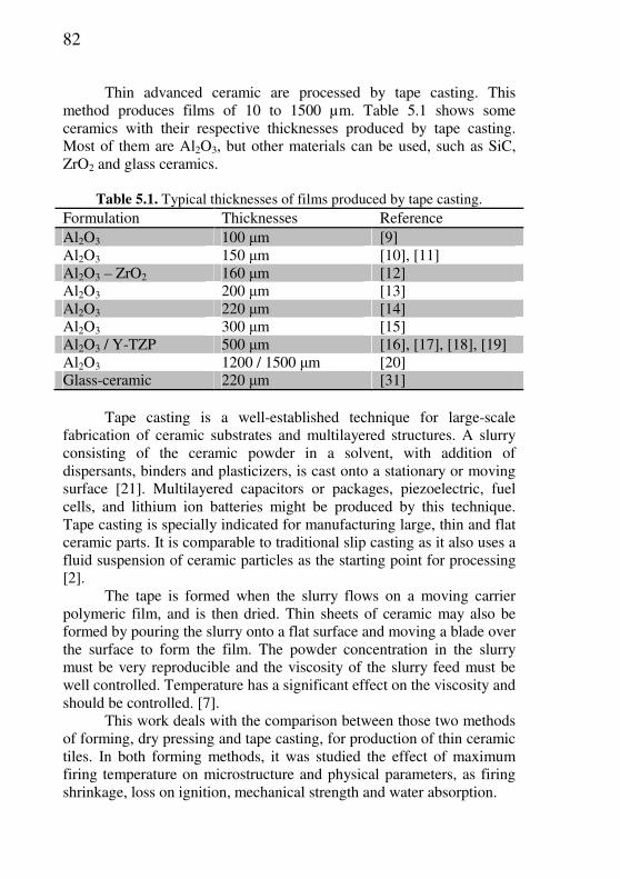
82
Thin advanced ceramic are processed by tape casting. This method produces films of 10 to 1500 µm. Table 5.1 shows some ceramics with their respective thicknesses produced by tape casting. Most of them are Al2O3, but other materials can be used, such as SiC, ZrO2 and glass ceramics.
Table 5.1. Typical thicknesses of films produced by tape casting.
Formulation Thicknesses Reference Al2O3 100 µm [9] Al2O3 150 µm [10], [11] Al2O3 – ZrO2 160 µm [12] Al2O3 200 µm [13] Al2O3 220 µm [14] Al2O3 300 µm [15] Al2O3 / Y-TZP 500 µm [16], [17], [18], [19] Al2O3 1200 / 1500 µm [20] Glass-ceramic 220 µm [31]
Tape casting is a well-established technique for large-scale
fabrication of ceramic substrates and multilayered structures. A slurry consisting of the ceramic powder in a solvent, with addition of dispersants, binders and plasticizers, is cast onto a stationary or moving surface [21]. Multilayered capacitors or packages, piezoelectric, fuel cells, and lithium ion batteries might be produced by this technique. Tape casting is specially indicated for manufacturing large, thin and flat ceramic parts. It is comparable to traditional slip casting as it also uses a fluid suspension of ceramic particles as the starting point for processing [2].
The tape is formed when the slurry flows on a moving carrier polymeric film, and is then dried. Thin sheets of ceramic may also be formed by pouring the slurry onto a flat surface and moving a blade over the surface to form the film. The powder concentration in the slurry must be very reproducible and the viscosity of the slurry feed must be well controlled. Temperature has a significant effect on the viscosity and should be controlled. [7].
This work deals with the comparison between those two methods of forming, dry pressing and tape casting, for production of thin ceramic tiles. In both forming methods, it was studied the effect of maximum firing temperature on microstructure and physical parameters, as firing shrinkage, loss on ignition, mechanical strength and water absorption.
83
5.2. EXPERIMENTAL PROCEDURE
5.2.1. Industrial step The ceramic tile batch was prepared in industrial scale by wet
milling and spray drying. The porcelain tile mix was composed by three clays, kaolin and talc. The chemical analysis of the raw materials was determined by X-ray fluorescence (Philips PW 2400). Milling of the raw materials was performed during 11 h in a discontinuous ball mill (11,400 L inner volume, with high-alumina coating and grinding balls). The slip presented 4.3 wt% particles retained in a 325 ASTM mesh sieve. Sodium silicate (15 wt% Na2O, and 32 wt% SiO2; 1580 kg·m-³) was used as a dispersant. The density of the slip was determined by pycnometry and viscosity was measured by a Brookfield viscometer (Model RVDVII, shear rate of 20 rpm). The particle size distribution of the slip was determined by laser diffraction (CILAS model 1064) with the sample dispersed in water using ultra-sound (60 s) to avoid agglomeration.
After milling, the slip was discharged into an underground tank with 40 ton capacity. During the discharge process, a vibrating sieve (60 ASTM mesh) was used for separation of undesirable particles. A binder (0.5 wt% polyethylene glycol, Tenacer, Zschimmer& Schwarz, 1210 kg·m-3, pH 7.2), was added in the tank and the slip was stirred during 24 h for complete homogenization. Then, 100 kg of slip was taken apart for the tape casting process. After homogenization, the slip was spray-dried. The spray-dried powder was stored during 24 h in an 80 ton silo. The moisture content of the powder was determined using a moisture meter (Ohaus, MB35 Halogen) and the granulometry was measured by sieving, using a vibrational system with 35, 50, 100 and 200 ASTM mesh sieves during 5 min at 60 Hz. A certain mass (150 kg) of the spray-dried powder was separated to be used in the pressing process.
5.2.2. Laboratory step
Forming, drying and firing of the ceramics tiles were carried out
in laboratory scale. Two forming processes were applied: dry pressing and tape casting. In both the final thickness of formed tiles was ~2 mm. Pressing was performed in a semi-automatic hydraulic press (Gabbrielli Sesto Fiorentino) with 12.3 MPa of pressure. The pressed samples presented after drying the same bulk density of the samples shaped by tape casting.
84
The doctor blade of the tape caster was adjusted to define the thickness of the casting film. The deposition on a plastic film was performed manually. The samples were dried at room temperature for 24 h and then cut into dimensions of 30 × 100 mm, which corresponds to the approximate dimensions of the tiles shaped by dry pressing.
Due to the high percentage of water used during the forming of the porcelain by tape casting, it was necessary to use additives that minimize the impacts of drying shrinkage, reducing the probability of cracks in materials. Was used 5 wt% of the plasticizer glycerol.
All properties studies at different levels were obtained as the arithmetic mean of 20 specimens.
The specimens conformed by pressing were dried in a drying chamber at 110˚C ± 10˚C for 24 h, while the specimens shaped by tape casting were dried at room temperature (25˚C) for 6 days, followed by 24 h of drying in a drying chamber at 110˚C ± 10˚C.
Bulk density of green bodies was characterized by the Archimedes principle. The samples were fired in a continuous roller kiln (Nassetti, Italy) at maximum firing temperatures of 1180, 1200 and 1220˚C with heating and cooling rates of 40˚C/min.
5.2.3. Characterization of fired tiles The linear shrinkage and loss on ignition of the ceramic tiles were
determined after firing. The linear shrinkage was determined using a caliper, and the loss on ignition by the calcination method (at each temperature and firing cycle). The mechanical strength was measured by the three-loading method (Gabbrielli Sesto Fiorentino, Italy) according to ISO 10545 [22]. The water absorption by the boiling water method was also performed following ISO 10545 [23]. The microstructural analysis was carried out on the fractured surface of the samples using a Scanning Electron Microscope (SEM, Philips XL30, Netherlands). The XRD was determined by X-ray diffactometer (XRD, Philips X-Pert, CuKα, 40kV and 30mA accelerating voltage, 2θ 1-80º interval, 0.02000º Scan Step Size and 1.00s Scan Step Time). All results were subjected to an analysis of variance (ANOVA) [24].
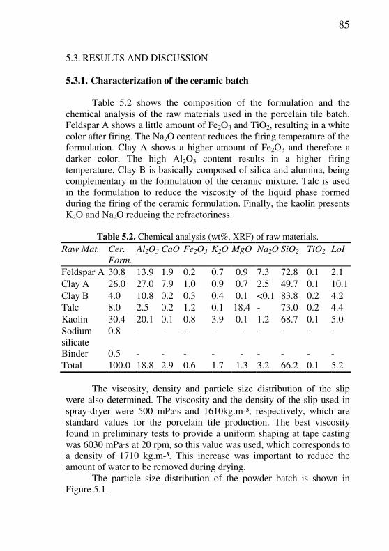
85
5.3. RESULTS AND DISCUSSION
5.3.1. Characterization of the ceramic batch Table 5.2 shows the composition of the formulation and the
chemical analysis of the raw materials used in the porcelain tile batch. Feldspar A shows a little amount of Fe2O3 and TiO2, resulting in a white color after firing. The Na2O content reduces the firing temperature of the formulation. Clay A shows a higher amount of Fe2O3 and therefore a darker color. The high Al2O3 content results in a higher firing temperature. Clay B is basically composed of silica and alumina, being complementary in the formulation of the ceramic mixture. Talc is used in the formulation to reduce the viscosity of the liquid phase formed during the firing of the ceramic formulation. Finally, the kaolin presents K2O and Na2O reducing the refractoriness.
Table 5.2. Chemical analysis (wt%, XRF) of raw materials. Raw Mat. Cer.
Form.
Al2O3 CaO Fe2O3 K2O MgO Na2O SiO2 TiO2 LoI
Feldspar A 30.8 13.9 1.9 0.2 0.7 0.9 7.3 72.8 0.1 2.1 Clay A 26.0 27.0 7.9 1.0 0.9 0.7 2.5 49.7 0.1 10.1 Clay B 4.0 10.8 0.2 0.3 0.4 0.1 <0.1 83.8 0.2 4.2 Talc 8.0 2.5 0.2 1.2 0.1 18.4 - 73.0 0.2 4.4 Kaolin 30.4 20.1 0.1 0.8 3.9 0.1 1.2 68.7 0.1 5.0 Sodium silicate
0.8 - - - - - - - - -
Binder 0.5 - - - - - - - - - Total 100.0 18.8 2.9 0.6 1.7 1.3 3.2 66.2 0.1 5.2
The viscosity, density and particle size distribution of the slip were also determined. The viscosity and the density of the slip used in spray-dryer were 500 mPa·s and 1610kg.m-³, respectively, which are standard values for the porcelain tile production. The best viscosity found in preliminary tests to provide a uniform shaping at tape casting was 6030 mPa·s at 20 rpm, so this value was used, which corresponds to a density of 1710 kg.m-³. This increase was important to reduce the amount of water to be removed during drying.
The particle size distribution of the powder batch is shown in Figure 5.1.

86
Figure 5.1. Particle size distribution of the porcelain tile batch.
The moisture content of the spray-dried granules was 6.2 wt%.
The size distribution of the spray-dried powder is shown in Table 5.3. The weight percentages refer to the fraction of the spray-dried powder retained in the sieves.
Table 5.3. Size distribution of the spray-dried powder. Sieve ASTM mesh
(µm)
#35
(500)
#50
(297)
#100
(149)
#200
(74)
<74
µm
Retained (wt %) 39.7 50.7 7.9 0.7 0.4
A suitable packaging during pressing is the result of a adequate flow and size distribution of the ceramic powder. Spray-dried powders smaller than 125 µm are those having less fluidity during pressing. Powders with higher fluidity are those in the range of 125 to 500 µm [25], which corresponds to the spray-dried powder used is this work.
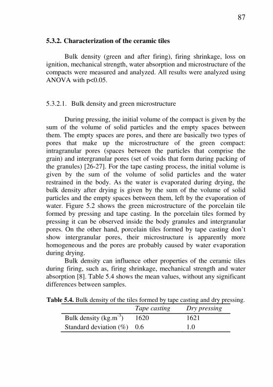
87
5.3.2. Characterization of the ceramic tiles Bulk density (green and after firing), firing shrinkage, loss on
ignition, mechanical strength, water absorption and microstructure of the compacts were measured and analyzed. All results were analyzed using ANOVA with p<0.05.
5.3.2.1. Bulk density and green microstructure During pressing, the initial volume of the compact is given by the
sum of the volume of solid particles and the empty spaces between them. The empty spaces are pores, and there are basically two types of pores that make up the microstructure of the green compact: intragranular pores (spaces between the particles that comprise the grain) and intergranular pores (set of voids that form during packing of the granules) [26-27]. For the tape casting process, the initial volume is given by the sum of the volume of solid particles and the water restrained in the body. As the water is evaporated during drying, the bulk density after drying is given by the sum of the volume of solid particles and the empty spaces between them, left by the evaporation of water. Figure 5.2 shows the green microstructure of the porcelain tile formed by pressing and tape casting. In the porcelain tiles formed by pressing it can be observed inside the body granules and intergranular pores. On the other hand, porcelain tiles formed by tape casting don’t show intergranular pores, their microstructure is apparently more homogeneous and the pores are probably caused by water evaporation during drying.
Bulk density can influence other properties of the ceramic tiles during firing, such as, firing shrinkage, mechanical strength and water absorption [8]. Table 5.4 shows the mean values, without any significant differences between samples.
Table 5.4. Bulk density of the tiles formed by tape casting and dry pressing.
Tape casting Dry pressing
Bulk density (kg.m-3) 1620 1621 Standard deviation (%) 0.6 1.0

88
Figure 5.2. Green microstructure of the ceramic tiles: a) Pressing; b) Tape
Casting.
5.3.2.2. Firing shrinkage Distinct behaviors can be observed for firing shrinkage as a
function of the forming method and firing temperature (Figure 5.3). For materials fired at 1180˚C, the firing shrinkage was higher using tape casting. At 1200˚C there is no significant difference between the means and at 1220˚C firing shrinkage was higher for the pressed tiles.
(a)
(b)
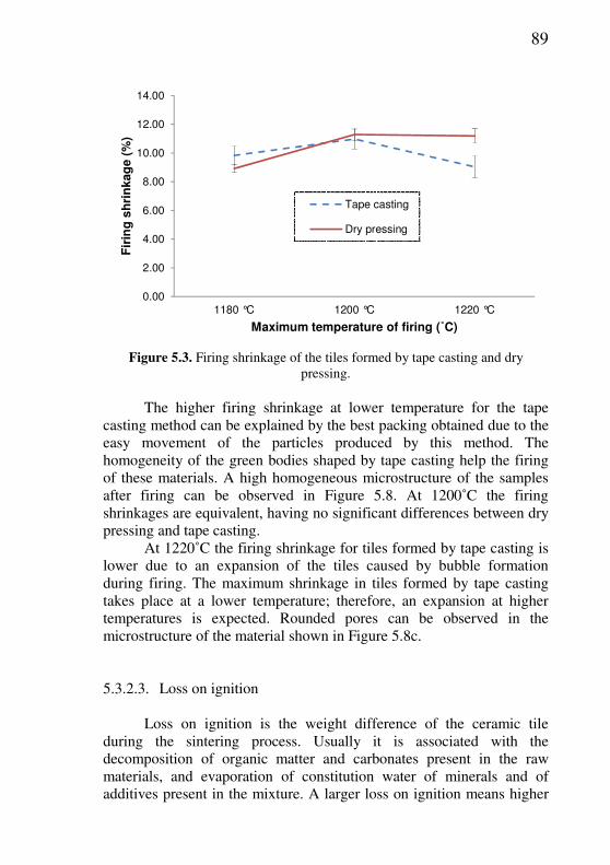
89
0.00
2.00
4.00
6.00
8.00
10.00
12.00
14.00
1180 °C 1200 °C 1220 °C
Fir
ing
sh
rin
kag
e (
%)
Maximum temperature of firing (˚C)
Tape casting
Dry pressing
Figure 5.3. Firing shrinkage of the tiles formed by tape casting and dry
pressing. The higher firing shrinkage at lower temperature for the tape
casting method can be explained by the best packing obtained due to the easy movement of the particles produced by this method. The homogeneity of the green bodies shaped by tape casting help the firing of these materials. A high homogeneous microstructure of the samples after firing can be observed in Figure 5.8. At 1200˚C the firing shrinkages are equivalent, having no significant differences between dry pressing and tape casting.
At 1220˚C the firing shrinkage for tiles formed by tape casting is lower due to an expansion of the tiles caused by bubble formation during firing. The maximum shrinkage in tiles formed by tape casting takes place at a lower temperature; therefore, an expansion at higher temperatures is expected. Rounded pores can be observed in the microstructure of the material shown in Figure 5.8c.
5.3.2.3. Loss on ignition Loss on ignition is the weight difference of the ceramic tile
during the sintering process. Usually it is associated with the decomposition of organic matter and carbonates present in the raw materials, and evaporation of constitution water of minerals and of additives present in the mixture. A larger loss on ignition means higher

90
volumes of gases released during firing. If the gases are fully released before the formation of vitreous phase during firing, defects like holes in the finished product are avoided [28]. It is observed in Figure 5.4 a higher loss on ignition in tiles formed by tape casting. This is due to the plasticizer used (glycerol), which has a boiling point of 290˚C.
0.00
1.00
2.00
3.00
4.00
5.00
6.00
7.00
8.00
9.00
10.00
1180 °C 1200 °C 1220 °C
Lo
ss
on
ig
nit
ion
(%
)
Maximum temperature of firing (˚C)
Tape casting
Dry pressing
Figure 5.4. Loss on ignition of the tiles formed by tape casting and dry
pressing.
5.3.2.4. Mechanical strength The mechanical strength measured as modulus of rupture
presented higher values in the tiles formed by tape casting. With the maximum temperature of 1180˚C, the tiles formed by tape showed mechanical strength 78% higher than those formed by pressing. At the temperature of 1200˚C, this difference in mechanical strength was 86%. Figure 5.5 shows the results of mechanical strength of the tiles studied.

91
0.00
10.00
20.00
30.00
40.00
50.00
60.00
70.00
80.00
90.00
1180 °C 1200 °C 1220 °C
Mo
du
lus o
f ru
ptu
re (
MP
a)
Maximum temperature of firing (˚C)
Tape casting
Dry pressing
Figure 5.5. Mechanical strength of the tiles formed by tape casting and dry
pressing. The mechanical strength measured as breaking load presented
higher values in the tiles formed by tape casting (Figure 5.6). The ISO 13006 standard requires for tiles with water absorption minor than 0.5%, value of breaking load above 700 N, so in both cases the breaking load is below the minimum required. Tiles with breaking strength less than 400 N are intended for use on walls only and this must be indicated by the manufacturer. But, even with applying the product only in the wall, the breaking load should not be less than 200 N [29]. Thus, ceramic tiles with reduced thickness, as 2 mm, can be manufactured by tape casting for use on walls. The results show that at 1200˚C the breaking load for tiles produced by tape casting is two times bigger than ceramic tiles produced by dry pressing.
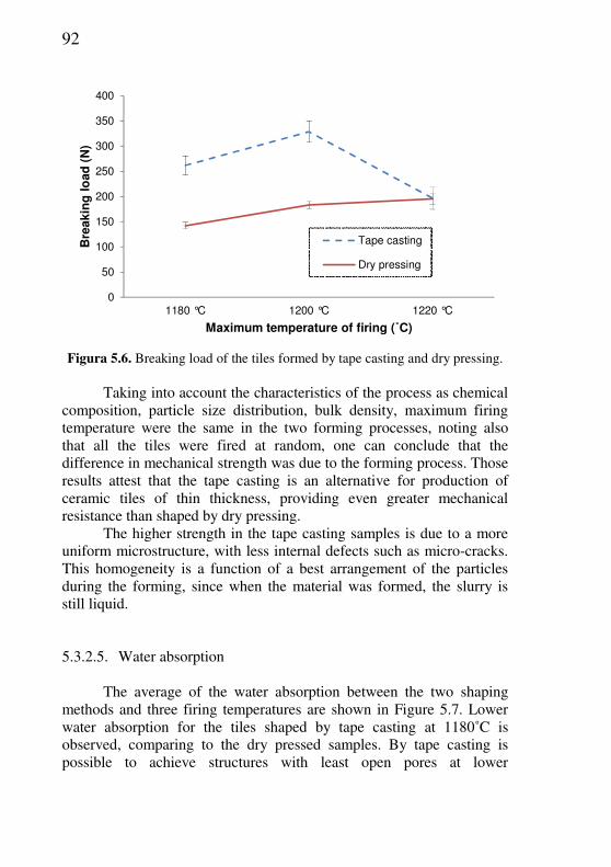
92
0
50
100
150
200
250
300
350
400
1180 °C 1200 °C 1220 °C
Bre
akin
g l
oad
(N
)
Maximum temperature of firing (˚C)
Tape casting
Dry pressing
Figura 5.6. Breaking load of the tiles formed by tape casting and dry pressing.
Taking into account the characteristics of the process as chemical
composition, particle size distribution, bulk density, maximum firing temperature were the same in the two forming processes, noting also that all the tiles were fired at random, one can conclude that the difference in mechanical strength was due to the forming process. Those results attest that the tape casting is an alternative for production of ceramic tiles of thin thickness, providing even greater mechanical resistance than shaped by dry pressing.
The higher strength in the tape casting samples is due to a more uniform microstructure, with less internal defects such as micro-cracks. This homogeneity is a function of a best arrangement of the particles during the forming, since when the material was formed, the slurry is still liquid.
5.3.2.5. Water absorption
The average of the water absorption between the two shaping
methods and three firing temperatures are shown in Figure 5.7. Lower water absorption for the tiles shaped by tape casting at 1180˚C is observed, comparing to the dry pressed samples. By tape casting is possible to achieve structures with least open pores at lower
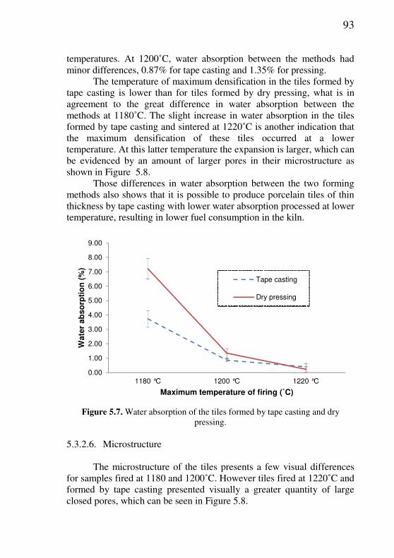
93
temperatures. At 1200˚C, water absorption between the methods had minor differences, 0.87% for tape casting and 1.35% for pressing.
The temperature of maximum densification in the tiles formed by tape casting is lower than for tiles formed by dry pressing, what is in agreement to the great difference in water absorption between the methods at 1180˚C. The slight increase in water absorption in the tiles formed by tape casting and sintered at 1220˚C is another indication that the maximum densification of these tiles occurred at a lower temperature. At this latter temperature the expansion is larger, which can be evidenced by an amount of larger pores in their microstructure as shown in Figure 5.8.
Those differences in water absorption between the two forming methods also shows that it is possible to produce porcelain tiles of thin thickness by tape casting with lower water absorption processed at lower temperature, resulting in lower fuel consumption in the kiln.
0.00
1.00
2.00
3.00
4.00
5.00
6.00
7.00
8.00
9.00
1180 °C 1200 °C 1220 °C
Wate
r ab
so
rpti
on
(%
)
Maximum temperature of firing (˚C)
Tape casting
Dry pressing
Figure 5.7. Water absorption of the tiles formed by tape casting and dry
pressing.
5.3.2.6. Microstructure The microstructure of the tiles presents a few visual differences
for samples fired at 1180 and 1200˚C. However tiles fired at 1220˚C and formed by tape casting presented visually a greater quantity of large closed pores, which can be seen in Figure 5.8.

94
According to the sintering process, when the density of the tile tend to be null, the glassy phase formed involves practically all the pores, remaining inside the body, isolating them from the external environment, and giving rise to closed porosity of the product. Due to high surface tension of the film of glassy phase which involves the pores, the gas starts to be trapped inside the compact, prevented from leaving. From this moment on, when the points of interconnection between the pores and the external environment do not exist, the two mechanisms act directly in opposite ways [30].
The gas entrapped within the pores hinders the progress of the laminar flow of the vitreous phase, and as this flow advances, the pressure of gas trapped within the pores increases, due to the decrease in pore volume, becomes increasingly difficult to densification. The temperature rise, followed by thermal cycling, also contributes to the increased internal pressure of the gases, at the same time reducing the surface tension of the glassy phase, until it reaches a point where the internal pressure of the gases trapped within the pores exceed the surface tension value of the vitreous phase, causing the increase of the pore volume, causing a phenomenon known as swelling or stuffing pore [30].
Analyzing the values of water absorption and firing shrinkage in two forming methods it can be deduced that sintering occurs faster with the tiles shaped by tape casting. This can be confirmed by the higher shrinkage and lower water absorption at 1180˚C.
As the maximum densification of the tiles formed by tape casting occurs at a lower temperature, it is expected that the swelling of the pores also happen at a lower temperature, which can be evidenced by the larger pores shown in Figure 5.8c.
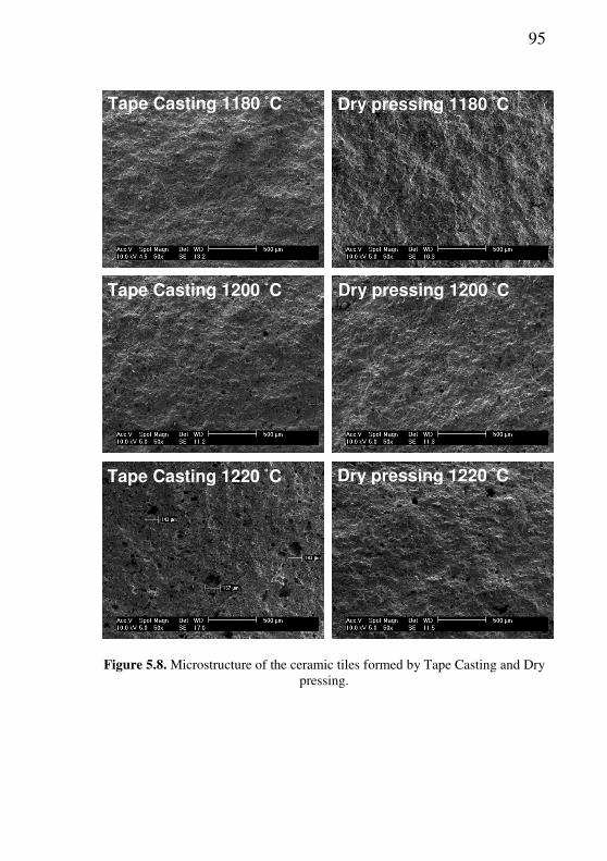
95
Figure 5.8. Microstructure of the ceramic tiles formed by Tape Casting and Dry
pressing.
Tape Casting 1180 ˚C
Tape Casting 1200 ˚C
Dry pressing 1180 ˚C
Dry pressing 1200 ˚C
Tape Casting 1220 ˚C Dry pressing 1220 ˚C

96
5.3.2.7. XRD
The phase composition of the porcelain tiles shaped by dry pressing and tape casting as a function of the firing temperature is shown in Figures 5.9 and 5.10 respectively. Observing the background of the diffractograms shown in Figure 5.10, the area under the spectra, the tape casted samples show a higher background area (not quantified) for any temperature in comparison with the dry pressed samples (Figure 5.9). The background area is related with the amount of amorphous or glassy phase. Therefore, the tape casted tiles show a higher glassy phase than the pressed tiles, which can explain the behavior of the tape casted tiles in comparison with the pressed ones.
Regarding the crystalline phases, all samples show the same phases, quartz, regardless the shaping process or sintering temperature used. The only difference between the shape processing and firing temperature is the intensity of the quartz phase, shown by the height of the peaks in the spectra. As expected, the higher the firing temperature, the higher the peak of quartz for all processing conditions.
Figure 5.9. XRD of the porcelain tiles formed by pressing.

97
Figure 5.10. XRD of the porcelain tiles formed by tape casting.

98
5.4. CONCLUSIONS Tape casting can be considered an alternative for production of
the thin ceramic tiles. The results show that for processed tapes, the sintering reactions occur at lower temperatures.
For ceramic tiles processed under the same conditions, the cast tapes process has at 1180˚C a higher firing shrinkage, but at 1220˚C the firing shrinkage is lower, due to the increase of the sizes of internal pores of the material.
Considering the mechanical strength, tape casting presented higher values than pressing process. On the other hand, the water absorption is lower at tape casted porcelain tiles.
The microstructures of the tiles formed by tape casting presents lower porosity at 1180˚ and higher at 1220˚C. The higher porosity appears in the latter temperature due the higher swelling on these tiles, as the temperature of maximum densification occurred in lower value.
5.5. REFERENCES
[1] KING, A.G. Ceramic technology and processing. Norwich, NY, p.134, 2002.
[2] RIEDEL, R.; CHEN I-W. Ceramics Science and Technology:
Structures. Wiley-VCH Verlag GmbH & Co. KGaA, Weinheim, v.1, 2008.
[3] TERPSTRA, R.A.; PEX, P.P.; VRIES, A. H. Ceramic Processing. 1.ed. Chapman & Hall. London, UK., p.102, 1995.
[4] CARBONCHI, C.; REGINELLI, M. Analysis of low-thickness porcelain tile body. Ceram. World Rev., v.94, p.66-72, 2011.
[5] SÁNCHEZ, E. et al. Porcelain tile: Almost 30 years of steady scientific-technological evolution. Ceram. Int., v.36, p.831-845, 2010.
[6] GOZZI, A. et al. Technological Behaviour of Low-thickness Ceramic Tile. Ceram. World Rev., v.83, p.78-80, 2009.
[7] REED, J.S. Principles of ceramic processing. 2.ed. New York: John Wiley & Sons, Inc., 1995.
99
[8] GUERRIERI, G. et al. Raw Material Preparation and Forming of
Ceramic Tiles. ACIMAC: Associazione Costruttori Italiani Macchine Attrezzature per Ceramica, p.340, 2004.
[9] LINDQVIST, K.; LIDEN, E.; Preparation of Alumina Membranes by tape casting and Dip Coating. J. Eur. Ceram. Soc., v.17, p.359-366, 1997
[10] KIENNEMANN, J. Drying mechanisms and stress development in aqueous alumina tape casting. J. Eur. Ceram. Soc., v.25, p.1551-1564, 2004.
[11] CHERNENKO, V. et al. Thickness dependence of transformation characteristics of Ni-Mn-Ga thin films deposited on alumina: Experiment and modeling. Mat. Sci. .Eng., p.438-440, 2006.
[12] CHARTIER, T.; ROUXEL, T. Tape-Cast Alumina-Zirconia Laminates: Processing and Mechanical Properties. J. Eur. Ceram. Soc., p.299-308, 1997.
[13] GUILLON, O.; KRAUB, S.; RODEL, J. Influence of thickness on the constrained sintering of alumina films. J. Eur. Ceram. Soc., v.27, p.2623-2627, 2007.
[14] DOREAU, F. et al. Mechanical and Lamination Properties of Alumina Green Tapes Obtained by Aqueous Tape-casting. J. Eur.
Ceram. Soc., v.19, p.2867-2873, 1999.
[15] GREENWOOD, R.; RONCARI, E.; GALASSI, C. Preparation of Concentrated Alumina Suspensions for tape casting. J. Eur. Ceram.
Soc., v.17, p.1393-1401, 1997.
[16] SÁNCHEZ-HERENCIA, A.; GURAUSKIS, J.; BAUDIN, C. Processing of Al2O3/Y-TZP laminates from water-based cast tapes. Composites: Part B. v.37, p.499-508, 2006.
[17] GURAUSKIS, J.; SÁNCHEZ-HERENCIA, A.; BAUDIN, C. Al2O3 / Y-TZP and Y-TZP materials fabricated by stacking layers obtained by aqueous tape casting. J. Eur. Ceram. Soc., v.26, p.1489-1496, 2006.
[18] ALBANO, M.; GARRIDO, L. Influence of the slip composition on the properties of tape-cast alumina substrates. Ceram. Int., v.31, p.57-66, 2005.

100
[19] BALAKRISHNAN, G. et al. Structural and optical properties of alumina thin films prepared by pulsed laser deposition. Thin Solid
Films, v.518, p.3898-3902, 2010.
[20] ZHANG, Y.; QIN, C.; BINNER, J. Processing multi-channel alumina membranes by tape casting latex-based suspensions. Ceram.
Int. v.32, p.811-818, 2006.
[21] HOTZA, D.; GREIL, P. Review: Aqueous tape casting of ceramic powders. Mat. Sci. Eng., v.202, p.206-217, 1995.
[22] ISO 10545-4: Ceramic Tiles – Part 4: Determination of modulus of rupture and breaking strength, second edition, 2004.
[23] ISO 10545-3: Ceramic Tiles – Part 3: Determination of water absorption, apparent porosity, apparent relative density and bulk density, 1995.
[24] MONTGOMERY, D.C.; RUNGER, G.C. Applied Statistics and Probability for Engineers. Wiley, 2002.
[25] EMILIANI, G.P.; CORBARA, F. Tecnologia cerâmica. 2.ed. Faenza: Gruppo Editoriale Faenza Editrice, p.198, 2001.
[26] ALVES, H.J.; MELCHIADES, F.G.; BOSCHI, A.O. Effect of spray-dried powder granulometry on the porous microstructure of polished porcelain tile. J. Eur. Ceram. Soc., v.30, p.1259-1266, 2010.
[27] DE PAULA, G.R.; QUINTEIRO, E.; BOSCHI, A.O. Efeito do teor de umidade e da pressão de prensagem sobre as características de revestimentos cerâmicos. Cerâmica Industrial, São Paulo, v.2, n.3/4, p.28-31, maio/ago. 1997.
[28] ALBERO, J.L.A. et al. Defectos de Fabricación de Pavimentos y
Revestimentos Cerámicos. Valência: AICE, 1991.
[29] ISO 13006, Ceramic Tiles: Definitions, Classification, Characteristics and Marking, International Organization for Standardization, 1998.
[30] LENGLER, H.C.M. Tese de doutorado – Controle da Porosidade
em Fases Vítreas Formadas pela ação de Fundentes em Cerâmicas Gresificadas - PPGEM – UFRGS – Porto Alegre/RS, 2006.
[31] HAUSOL, T. et al. Corrugated glass-ceramics from LZSA cast tapes. J. Mat. Proc. Tech., v.210, p.1556-1561, 1561.
101
6. CONCLUSÕES GERAIS E SUGESTÕES PARA TRABALHOS FUTUROS
6.1. CONCLUSÕES
As principais conclusões do presente trabalho foram:
• A temperatura máxima de queima afeta significativamente a microestrutura e as propriedades físicas de porcelanatos de baixa espessura.
• A espessura do porcelanato tem influência significativa sobre a sua microestrutura e propriedades físicas, como retração linear de queima, perda ao fogo, carga de ruptura, absorção de água e densidade aparente após queima. Quanto menor a espessura, maior a facilidade de densificação do revestimento.
• A pressão de prensagem exerce influência significativa na densidade aparente a cru e retração linear de queima dos porcelanatos de baixa espessura. Em altas pressões de compactação, a pressão de prensagem não exerce influência significativa sobre perda ao fogo, resistência mecânica, absorção de água e densidade aparente após queima.
• O ciclo de prensagem, ou seja, o tempo entre o início da prensagem até a máxima pressão, não apresenta efeito sobre as propriedades físicas dos revestimentos cerâmicos.
• Os métodos de conformação dos revestimentos cerâmicos, tais como prensagem e tape casting, exercem influências significativas sobre a microestrutura e propriedades físicas de porcelanatos de baixa espessura, como retração linear de queima, absorção de água, perda ao fogo e, principalmente, sobre a resistência mecânica.
• A resistência mecânica a flexão dos porcelanatos processados por tape casting e a carga de ruptura são maiores comparativamente aos porcelanatos compactados por prensagem, quando processados nas mesmas condições.

102
6.2. SUGESTÕES
Sugerem-se para continuidade dos trabalhos as seguintes ações: • Avaliar a influência da espessura na piroplasticidade dos
porcelanatos. • Estudar a eficiência de secagem de porcelanatos conformados
por tape casting. • Empregar novos aditivos, como ligantes, plastificantes e
defloculantes, para o processo tape casting com composição de porcelanato.
• Testar alternativas para aumentar a densidade aparente a verde nos materiais processados por tape casting.