thyssenkrupp drilling catálogo
DESCRIPTION
catalogueTRANSCRIPT

Drilling ToolsGeneral Catalog
ThyssenKrupp Materials FranceUne entreprise de ThyssenKrupp
Services
TK
CC2004 ThyssenKrupp.indd 1CC2004 ThyssenKrupp.indd 1 7/22/04 12:38:55 PM7/22/04 12:38:55 PM

Contents page
Steel making and forging 1
Heat treating and quality 2
Drill collar manufacturing 3
Drill collar size and connections 6
Drill collar make up torque 7
Forged square and hexagonal kellys 8
Forged heavy weight 10
Lifting plugs and subs 12
Integral stabilizers 13
Non-magnetic steels 14
Steels for the oil industry 15
Conversion Table Inches to Millimeters 16
All statements relating to the properties or utilisation of the materials and products mentioned in this brochure are solely for the purpose of description. Guarantees in respect to the existence of certain properties or utilisation of the material mentioned are only valid if agreed upon in writing.
CC2004 ThyssenKrupp.indd 2CC2004 ThyssenKrupp.indd 2 7/22/04 12:39:02 PM7/22/04 12:39:02 PM

3
Steel making and forging
Steel makingThyssenKrupp Drilling Tools are made from AISI-4145 H modified alloy steel, forged and fully heat treated to API and other specifications. ThyssenKrupp most modern steel plants use electric remelt furnaces, ladle refining and vacuum degassing.Raw material consists of selected steel scrap and ferro-alloys. Special care is taken to produce a clean and uniform steel during this triple melting process.The chemistry of the steel is verified continuously by 10-chemical analyses during the melting process.Further cleaning of the steel is provided with the bottom pouring method for ingots of larger sizes.Most of ThyssenKrupp Drilling Tools are made from bars poured by a custom designed continuous casting unit.
Using this slow process, continuous casting assures a uniform and homogeneous steel free of unwanted inclusions and gases.Excess material is instantly removed by a built-in gas cutting process which assures clean and uniform material up to the very end of each bar.
Steel GradesThyssenKrupp have also developed a new steel grade for use in Sour Service.This proprietary steel grade, 4145H Mod. 45 has the same mechanical properties as AISI 4145 H, but offers vastly improved resistance to H2S embrittlement.Drilling tools can also be made from non-magnetic steels for directional requirements and MWD/LWD Services. Please refer to page 14 for details.
ForgingMost ThyssenKrupp Drilling Tools are forged on a unique radial forge designed to provide shaped forgings and bars for kelly’s, drill collars, heavy weights and other ThyssenKrupp drilling equipment.Forgings are tough, ductile, have uniform grain flow and metallurgical structures to assure material integrity, fatigue resistance and strength. The forging cycle on a radial hammer forge is extremely short and excellent time-temperature control can be achieved. The bar is turned by manipulators. A multitude of radially arranged hammers allows this forge to shape round forgings to desired dimensions. The forge is totally computer controlled.
Forging heavy weightFurnace
CC2004 ThyssenKrupp.indd 3CC2004 ThyssenKrupp.indd 3 7/22/04 12:39:16 PM7/22/04 12:39:16 PM

4
Heat treating and quality
Heat treating
Following this unique forging process is a custom designed heat treating line. Each bar is moved and turned on skewed rollers through the heat treating furnace which gives uniform heating from all sides.
Each bar is then water quenched by ring jets in a barrel type quenching unit. This process provides the required strength of the forged material. In order to obtain the mechanical properties of the
finished product, the bars are tempered in a tempering furnace to complete the heat treating process.
Quality
ThyssenKrupp Drilling Tools are made in most recent manufacturing plants and to highest standards. All products are made to API Specification 7 standards.
In addition ThyssenKrupp Materials France guarantees that ThyssenKrupp Drilling Tools are meeting SQAIR standards (now replaced by NS-1).
Mill certificates and machining inspection certificates are provided with each product. ThyssenKrupp Materials France is an ISO-9002 supplier.
A ThyssenKruppMaterials company
ThyssenKrupp Materials France
TK
CC2004 ThyssenKrupp.indd 4CC2004 ThyssenKrupp.indd 4 7/22/04 12:39:21 PM7/22/04 12:39:21 PM

5
Ultimate tensile Yield Elongation(1) Reduction Impact Hardness(3)
strength strength of Area strength(2) psi psi % % J HB
135,000 100,000 15 min 45 min 50 min 285 to 341to 140,000 to 110,000
(1) L = 4 D(2) ASTM A 370 Charpy - V)(3) one inch below surface
Mechanical properties per API 7
Slick drill collar
Drill collar manufacturing
Steel gradesThyssenKrupp Drill Collars are made from AISI 4145 modified alloy steel, heat treated to API standards. Chemical purity is assured by careful scrap selection and reduction of residual elements (Ph and S for example) to a minimum.Continuous casting and bottom pouring of ingots provide a clean, homoge neous steel for all of ThyssenKrupp Drilling Tools.Drill collars are also available from non-magnetic steel for directional services and 4145H Mod. 45 for H2S environments where embrittlement can occur.
ForgingThyssenKrupp Drill Collars are forged on a unique radial hammer forge based on the latest forging technology.
Heat treatingHeat treating, quenching and tempering of this material is the most critical process in the making of steel bars for drill collars.Customs designed heat treating equipment assures the continued success of this critical manufacturing phase.
BoringFollowing peeling, ultrasonic inspection and individual physical property analysis of each bar, the most important straightening operation takes place. Following this, the bars are bored by a battery of specially adapted boring machines. These precision borers provide extremely straight bores and a minimal step in the center.Gaging to API specifica tions with a 10 FT drift mandrel is standard practice for all bored bars.
End connectionsMachining of end connections is done on CNC machines with constant profile cutting tools. Thread profile, lead, depth, taper and stand-off are constantly inspected during and after machining. Following API gaging, thread roots are cold rolled to improve fatigue resistance of connections.
CC2004 ThyssenKrupp.indd 5CC2004 ThyssenKrupp.indd 5 7/22/04 12:39:33 PM7/22/04 12:39:33 PM

6
Drill collar manufacturing
NC35 3 1/4 3 15/64 2 3 15/64 3 3/8
NC38 (3 1/2 IF) 3 1/2 3 15/32 2 3 33/64 3 5/8
NC40 (4 FH) 4 3 21/32 2 3 25/32 4 1/8
NC44 4 4 2 4 3/16 4 1/8
NC46 (4 IF) 4 4 13/64 2 4 21/64 4 1/8
NC50 (4 1/2 IF) 4 4 5/8 2 4 3/4 4 1/8
NC56 4 1/2 4 51/64 3 5 18/64 4 5/8
NC61 5 5 15/64 3 5 56/64 5 1/8
NC70 5 1/2 5 63/64 3 6 47/64 5 5/8
NC77 6 6 35/64 3 7 27/64 6 1/8
4 1/2 FH 3 1/2 3 51/64 3 4 13/64 3 5/8
5 1/2 REG 4 1/4 4 1/2 3 4 56/64 4 3/8
6 5/8 REG 4 1/2 5 8/32 2 5 27/64 4 5/8
7 5/8 REG 4 3/4 5 56/64 3 6 13/32 4 7/8
8 5/8 REG 4 7/8 6 25/32 3 7 18/64 5
Length, Shoulder Taper of Face to Last Diameter of Area Behind Diameter Length, Shoulder Number(1) Thread Scratch Cylinder Area Cylinder Area of Pin Member Face to Groove or of Box Member, of Box Member, of Box Member, at Groove, of Box Member, Size and in. in. in. per ft. in. in. Style of Tol. ± 1/16 in. Tol. + 1/64 – 0 in. ± 1/4 in./ft. Tol. + 0 – 1/32 in. Tol. + 0, – 1/8 in. Connection* LX Dcb T.P.F. DrG LrG
Stress-relief features for drill collar connections
ConnectionsAll connections are phosphated to help prevention of galling during initial make-up.API or customer specified thread compounds are applied before fitting the connections with pressed steel thread protectors.
(1) Connections NC23, NC26 (2 3/8 IF) and NC31 (2 7/8 IF) do not have sufficient metal to accommodate stress-relief features.
LRG
45° ± 2°
30° ± 2°
+1/64” (0,40 mm)- 0”
13/64” (5,16 mm)± 1/8” (3,18 mm)1/2” (38,1 mm)
± 1/64” (0,40 mm)± 1/4” (6,35 mm) R
Box stress-relief groove
LX
Dcb
T.P.F.
± 1/64” (0,40 mm)1” (25,4 mm) R
± 1/4”(6,35 mm)
2” (50,8 mm)
± 1/4”(6,35 mm)
2” (50,8 mm)
30° ± 1°
Boreback box stress-relief feature
± 1/32” (0,79 mm)
DRG
1” (25,4 mm)45° ± 1°
1/4” (6,35 mm)± 1/64” (0,40 mm)
Pin stress-relief feature
CC2004 ThyssenKrupp.indd 6CC2004 ThyssenKrupp.indd 6 7/22/04 12:39:33 PM7/22/04 12:39:33 PM

7
Slip groove
Elevatorgroove
R coldworkedradius
Drillcollar OD
3”
3”
3”
18”+2
116”+
20”+2- 0
- 0
- 0
4”
10”
1”
Spiral drill collar
Drill collar manufacturing
Slick drill collarsThyssenKrupp slick drill collars are available for all typical sizes and bores.Surface finish of slick drill collars is achieved by a carefully controled peeling operation.All features such as stress relief grooves on connections and slip and elevator recesses are available on most sizes.
SpirallingSpiralling of drill collars reduces the dangers of differential pressure sticking particularly in deviated or horizontal holes. Spiral grooving of ThyssenKrupp collars provides sufficient depth in order to be effective.Spiralling of drill collars is available from sizes 4 3/4 in. to 11" 1/4 outside diameter.
10 9 1/8 9 1/2 1/4
9 3/4 8 7/8 9 1/4 1/4
9 1/2 8 5/8 9 1/4
9 1/4 8 3/8 8 3/4 1/4
9 8 1/8 8 1/2 1/4
8 1/2 7 3/4 8 3/16
8 7 1/4 7 1/2 3/16
7 3/4 7 7 1/4 3/16
7 1/2 6 3/4 7 3/16
7 1/4 6 1/2 6 3/4 3/16
7 6 1/4 6 1/2 3/16
6 3/4 6 6 1/4 3/16
6 1/2 5 7/8 6 1/8
6 1/4 5 5/8 5 3/4 1/8
6 5 3/8 5 1/2 1/8
5 3/4 5 1/8 5 1/4 1/8
4 3/4 4 1/4 4 3/8 1/8
4 1/8 3 11/16 3 3/4 1/8
Drill collar Diameter of elevator Diameter of slip Cold worked radius OD groove groove in. in. in. in.
Grooves
Slip and elevator groovesSlip and elevator grooves are-defined by API standard RP-7-G.
HardbandingThyssenKrupp offers several hardbanding options from fine particle hardbanding to our own smooth hardbanding design or special hardbanding options supplied by third parties.The ThyssenKrupp recommended hardbanding design is as follows:
● DRILL COLLARS without slip and elevator grooves: 10" long wear band at 30" minimum from the pin end
● DRILL COLLARS with slip and elevator grooves: 4" long wear band above elevator grooves, 1" band between grooves, 10" long wear band under slip groove.
● Standard application is raised (proud). Flush on request.
● Other configurations are available on request.
CC2004 ThyssenKrupp.indd 7CC2004 ThyssenKrupp.indd 7 7/22/04 12:39:34 PM7/22/04 12:39:34 PM
8
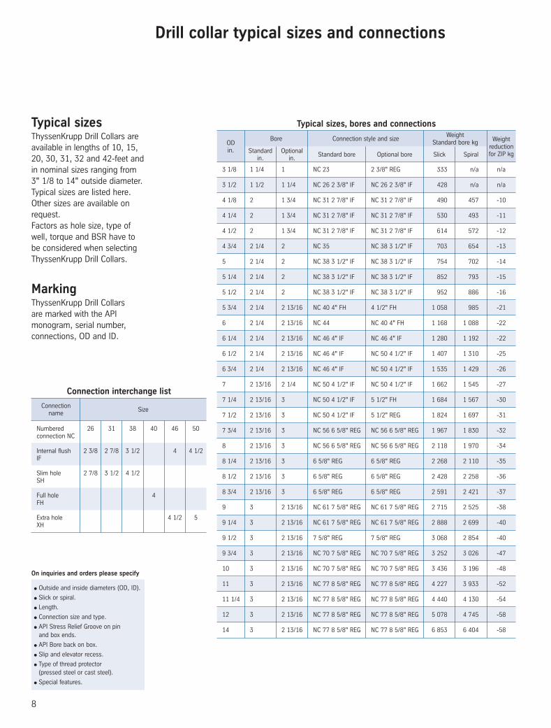
Drill collar typical sizes and connections
● Outside and inside diameters (OD, ID).
● Slick or spiral.
● Length.
● Connection size and type.
● API Stress Relief Groove on pin and box ends.
● API Bore back on box.
● Slip and elevator recess.
● Type of thread protector (pressed steel or cast steel).
● Special features.
On inquiries and orders please specify
3 1/8 1 1/4 1 NC 23 2 3/8" REG 333 n/a n/a
3 1/2 1 1/2 1 1/4 NC 26 2 3/8" IF NC 26 2 3/8" IF 428 n/a n/a
4 1/8 2 1 3/4 NC 31 2 7/8" IF NC 31 2 7/8" IF 490 457 -10
4 1/4 2 1 3/4 NC 31 2 7/8" IF NC 31 2 7/8" IF 530 493 -11
4 1/2 2 1 3/4 NC 31 2 7/8" IF NC 31 2 7/8" IF 614 572 -12
4 3/4 2 1/4 2 NC 35 NC 38 3 1/2" IF 703 654 -13
5 2 1/4 2 NC 38 3 1/2" IF NC 38 3 1/2" IF 754 702 -14
5 1/4 2 1/4 2 NC 38 3 1/2" IF NC 38 3 1/2" IF 852 793 -15
5 1/2 2 1/4 2 NC 38 3 1/2" IF NC 38 3 1/2" IF 952 886 -16
5 3/4 2 1/4 2 13/16 NC 40 4" FH 4 1/2" FH 1 058 985 -21
6 2 1/4 2 13/16 NC 44 NC 40 4" FH 1 168 1 088 -22
6 1/4 2 1/4 2 13/16 NC 46 4" IF NC 46 4" IF 1 280 1 192 -22
6 1/2 2 1/4 2 13/16 NC 46 4" IF NC 50 4 1/2" IF 1 407 1 310 -25
6 3/4 2 1/4 2 13/16 NC 46 4" IF NC 50 4 1/2" IF 1 535 1 429 -26
7 2 13/16 2 1/4 NC 50 4 1/2" IF NC 50 4 1/2" IF 1 662 1 545 -27
7 1/4 2 13/16 3 NC 50 4 1/2" IF 5 1/2" FH 1 684 1 567 -30
7 1/2 2 13/16 3 NC 50 4 1/2" IF 5 1/2" REG 1 824 1 697 -31
7 3/4 2 13/16 3 NC 56 6 5/8" REG NC 56 6 5/8" REG 1 967 1 830 -32
8 2 13/16 3 NC 56 6 5/8" REG NC 56 6 5/8" REG 2 118 1 970 -34
8 1/4 2 13/16 3 6 5/8" REG 6 5/8" REG 2 268 2 110 -35
8 1/2 2 13/16 3 6 5/8" REG 6 5/8" REG 2 428 2 258 -36
8 3/4 2 13/16 3 6 5/8" REG 6 5/8" REG 2 591 2 421 -37
9 3 2 13/16 NC 61 7 5/8" REG NC 61 7 5/8" REG 2 715 2 525 -38
9 1/4 3 2 13/16 NC 61 7 5/8" REG NC 61 7 5/8" REG 2 888 2 699 -40
9 1/2 3 2 13/16 7 5/8" REG 7 5/8" REG 3 068 2 854 -40
9 3/4 3 2 13/16 NC 70 7 5/8" REG NC 70 7 5/8" REG 3 252 3 026 -47
10 3 2 13/16 NC 70 7 5/8" REG NC 70 7 5/8" REG 3 436 3 196 -48
11 3 2 13/16 NC 77 8 5/8" REG NC 77 8 5/8" REG 4 227 3 933 -52
11 1/4 3 2 13/16 NC 77 8 5/8" REG NC 77 8 5/8" REG 4 440 4 130 -54
12 3 2 13/16 NC 77 8 5/8" REG NC 77 8 5/8" REG 5 078 4 745 -58
14 3 2 13/16 NC 77 8 5/8" REG NC 77 8 5/8" REG 6 853 6 404 -58
ODin. Standard
in.
Bore Connection style and size
Optionalin.
Standard bore Optional bore Slick Spiral
WeightStandard bore kg Weight
reduction for ZIP kg
Typical sizes, bores and connectionsTypical sizesThyssenKrupp Drill Collars are available in lengths of 10, 15, 20, 30, 31, 32 and 42-feet and in nominal sizes ranging from 3" 1/8 to 14" outside diameter.Typical sizes are listed here.Other sizes are available on request. Factors as hole size, type of well, torque and BSR have to be considered when selecting ThyssenKrupp Drill Collars.
MarkingThyssenKrupp Drill Collars are marked with the API monogram, serial number, connections, OD and ID.
Connection Size
name
Numbered 26 31 38 40 46 50 connection NC
Internal flush 2 3/8 2 7/8 3 1/2 4 4 1/2 IF
Slim hole 2 7/8 3 1/2 4 1/2 SH
Full hole 4 FH
Extra hole 4 1/2 5 XH
Connection interchange list
CC2004 ThyssenKrupp.indd 8CC2004 ThyssenKrupp.indd 8 7/22/04 12:39:34 PM7/22/04 12:39:34 PM

9
4 1/8 2 NC 31 2 7/8 IF 6 850
4 1/4
1 3/4 NC 31 2 7/8 IF 8 100
2 NC 31 2 7/8 IF 6 900
4 1/2
1 3/4 NC 31 2 7/8 IF 8 300
2 NC 31 2 7/8 IF 7 000
4 3/4
2 NC 38 3 1/2 IF 10 000
2 1/4 NC 35 10 800
5
2 NC 38 3 1/2 IF 13 950
2 1/4 NC 38 3 1/2 IF 12 900
5 1/4
2 NC 38 3 1/2 IF 14 700
2 1/4 NC 38 3 1/2 IF 13 030
5 1/2
2 NC 38 3 1/2 IF 14 900
2 1/4 NC 38 3 1/2 IF 12 900
5 3/4
2 1/4 NC 40 4 FH 17 300
2 13/16 4 1/2 FH 18 400
6
2 1/4 NC 44 23 500
2 13/16 NC 40 4 FH 13 000
6 1/4
2 1/4 NC 46 4 IF 28 050
2 13/16 NC 46 4 IF 22 500
Drill Make-up collar Bore Connection torque OD in. value in. ft x Ibs
6 1/2
2 1/4 NC 46 4 IF 28 350
2 13/16 NC 50 4 1/2 IF 29 600
6 3/4
2 1/4 NC 46 4 IF 28 650
2 13/16 NC 50 4 1/2 IF 32 470
7
2 1/4 NC 50 4 1/2 IF 38 600
2 13/16 NC 50 4 1/2 IF 32 800
7 1/4
2 13/16 NC 50 4 1/2 IF 33 100
3 5 1/2 FH 41 000
7 1/2
2 3/4 5 1/2 REG 37 000
2 13/16 NC 50 4 1/2 IF 34 400
7 3/4
2 13/16 NC 56 6 5/8 REG 48 250
3 NC 56 6 5/8 REG 45 700
8
2 13/16 NC 56 6 5/8 REG 48 250
3 NC 56 6 5/8 REG 45 700
8 1/4
2 13/16 6 5/8 REG 53 400
3 6 5/8 REG 50 750
8 1/2
2 13/16 6 5/8 REG 55 750
3 6 5/8 REG 53 150
Drill Make-up collar Bore Connection torque OD in. value in. ft x Ibs
8 3/4
2 13/16 6 5/8 REG 62 150
3 6 5/8 REG 60 000
9
2 13/16 NC 61 7 5/8 REG 68 400
3 NC 61 7 5/8 REG 65 700
9 1/4
2 13/16 NC 61 7 5/8 REG 73 000
3 NC 61 7 5/8 REG 70 500
9 1/2
2 13/16 7 5/8 REG 91 650
3 7 5/8 REG 88 600
9 3/4
2 13/16 NC 70 8 5/8 REG 108 000
3 NC 70 8 5/8 REG 105 000
10
2 13/16 NC 70 8 5/8 REG 108 900
3 NC 70 8 5/8 REG 106 000
11
2 13/16 NC 77 8 5/8 REG 150 000
3 NC 77 8 5/8 REG 146 000
11 1/4
2 13/16 8 5/8 REG 150 000
3 8 5/8 REG 146 000
Drill Make-up collar Bore Connection torque OD in. value in. ft x Ibs
Drill collar recommended make up torque
Make up torqueCalculations for recommended make-up torques are based on using a thread compound with 40% - 60% of weight of finely powdered metallic zinc or 60% of weight of finely powdered metallic lead with no more than 0.3% total active sulfur (caution: hazardous materials
in API SPEC-7, Appendix F) applied to all threads and shoulders and using the modified SCREW-JACK formula and a unit stress of 62500 psi in the box or pin whichever is weaker.Stress relief features are disregarded for make-up torque calculations.
Normal torque range is tabulated value plus 10%. High torques may be used in extreme service conditions.Calculations are based on new, clean and well lubricated connections. Thread compounds should not be contaminated with mud, water, sand, rust or oil.
Initial make-up of new ThyssenKrupp-Drill Collars should be carefully handled and ‘walk in’ with chain tongs is recommended. Connection should then be made-up to torque, broken out, inspected, relubricated and again made-up to full torque.
CC2004 ThyssenKrupp.indd 9CC2004 ThyssenKrupp.indd 9 7/22/04 12:39:35 PM7/22/04 12:39:35 PM
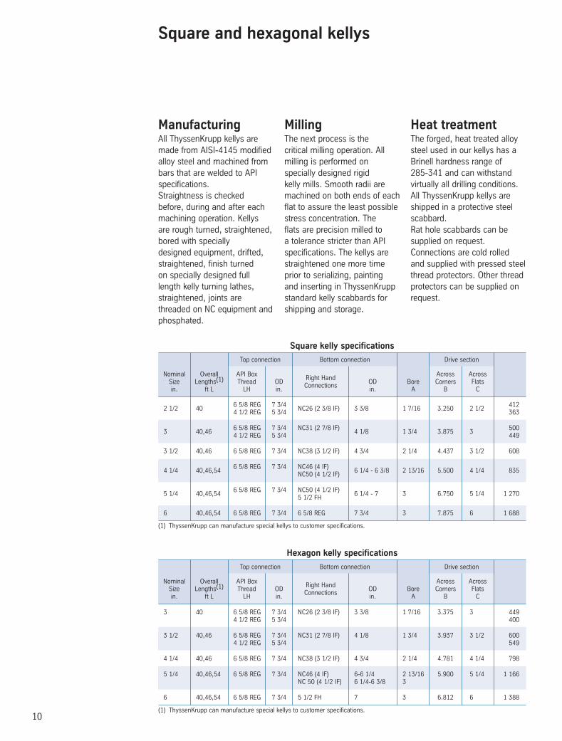
10
Approx. Wt. of
40 ft (kg) kelly
Approx. Wt. of
40 ft (kg) kelly
ManufacturingAll ThyssenKrupp kellys are made from AISI-4145 modified alloy steel and machined from
.Straightness is checked before, during and after each machining operation. Kellys are rough turned, straightened, bored with specially designed equipment, drifted, straightened, finish turned on specially designed full length kelly turning lathes, straightened, joints are threaded on NC equipment and phosphated.
MillingThe next process is the critical milling operation. All milling is performed on specially designed rigid kelly mills. Smooth radii are machined on both ends of each flat to assure the least possible stress concentration. The flats are precision milled to a tolerance stricter than API specifications. The kellys are straightened one more time prior to serializing, painting and inserting in ThyssenKrupp standard kelly scabbards for shipping and storage.
Heat treatmentThe forged, heat treated alloy steel used in our kellys has a Brinell hardness range of 285-341 and can withstand virtually all drilling conditions.All ThyssenKrupp kellys are shipped in a protective steel scabbard.Rat hole scabbards can be supplied on request.Connections are cold rolled and supplied with pressed steel thread protectors. Other thread protectors can be supplied on request.
(1) ThyssenKrupp can manufacture special kellys to customer specifications.
2 1/2 40
6 5/8 REG 7 3/4 NC26 (2 3/8 IF) 3 3/8 1 7/16 3.250 2 1/2
412 4 1/2 REG 5 3/4 363
3 40,46
6 5/8 REG 7 3/4 NC31 (2 7/8 IF) 4 1/8 1 3/4 3.875 3
500 4 1/2 REG 5 3/4 449
3 1/2 40,46 6 5/8 REG 7 3/4 NC38 (3 1/2 IF) 4 3/4 2 1/4 4.437 3 1/2 608
4 1/4 40,46,54
6 5/8 REG 7 3/4 NC46 (4 IF) 6 1/4 - 6 3/8 2 13/16 5.500 4 1/4 835
NC50 (4 1/2 IF)
5 1/4 40,46,54
6 5/8 REG 7 3/4 NC50 (4 1/2 IF) 6 1/4 - 7 3 6.750 5 1/4 1 270
5 1/2 FH
6 40,46,54 6 5/8 REG 7 3/4 6 5/8 REG 7 3/4 3 7.875 6 1 688
Nominal Overall API Box Right Hand
Across Across Size Lengths(1) Thread OD
Connections OD Bore Corners Flats
in. ft L LH in. in. A B C
Top connection Bottom connection Drive section
Square kelly specifications
Nominal Overall API Box Right Hand
Across Across Size Lengths(1) Thread OD
Connections OD Bore Corners Flats
in. ft L LH in. in. A B C
Top connection Bottom connection Drive section
(1) ThyssenKrupp can manufacture special kellys to customer specifications.
3 40 6 5/8 REG 7 3/4 NC26 (2 3/8 IF) 3 3/8 1 7/16 3.375 3 449 4 1/2 REG 5 3/4 400
3 1/2 40,46 6 5/8 REG 7 3/4 NC31 (2 7/8 IF) 4 1/8 1 3/4 3.937 3 1/2 600 4 1/2 REG 5 3/4 549
4 1/4 40,46 6 5/8 REG 7 3/4 NC38 (3 1/2 IF) 4 3/4 2 1/4 4.781 4 1/4 798
5 1/4 40,46,54 6 5/8 REG 7 3/4 NC46 (4 IF) 6-6 1/4 2 13/16 5.900 5 1/4 1 166 NC 50 (4 1/2 IF) 6 1/4-6 3/8 3
6 40,46,54 6 5/8 REG 7 3/4 5 1/2 FH 7 3 6.812 6 1 388
Hexagon kelly specifications
CC2004 ThyssenKrupp.indd 10CC2004 ThyssenKrupp.indd 10 7/22/04 12:39:35 PM7/22/04 12:39:35 PM
Square and hexagonal kellys
bars that are welded to APIspecifications

11
Forged hexagonal kellyForged square kelly
Forged square and hexagonal kellys
Top upset with
left hand
connection
Bottom upset withright handconnection
20”
16”
LOveralllength
LOveralllength
C
A
CB
20”
16”
A
BC
C
● Kelly type (hexagonal or square)
● Nominal size
● Overall length
● Bore-A
● Size and type of top connection
● Size and type of bottom connection
● Plain Shipping Scabbard or Rathole Drilling Scabbard
On inquiries and orders please specify
CC2004 ThyssenKrupp.indd 11CC2004 ThyssenKrupp.indd 11 7/22/04 12:39:36 PM7/22/04 12:39:36 PM
12
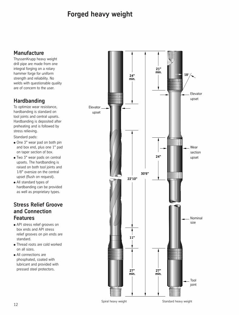
Forged heavy weight
21”min.
24”
30’6”
18°
Tooljoint
Nominalsize
Wear
section
upset
Elevator
upset
24”min.
27”min.
27”min.
Elevator
upset
11”
22’10”
Standard heavy weightSpiral heavy weight
ManufactureThyssenKrupp heavy weight drill pipe are made from one integral forging on a rotary hammer forge for uniform strength and reliability. No welds with questionable quality are of concern to the user.
HardbandingTo optimize wear resistance, hardbanding is standard on tool joints and central upsets.Hardbanding is deposited after preheating and is followed by stress relieving.
Standard pads:
● One 3" wear pad on both pin and box end, plus one 1" pad on taper section of box.
● Two 3" wear pads on central upsets. The hardbanding is raised on both tool joints and 1/8" oversize on the central upset (flush on request).
● All standard types of hardbanding can be provided as well as proprietary types.
Stress Relief Groove and Connection Features● API stress relief grooves on
box ends and API stress relief grooves on pin ends are standard.
● Thread roots are cold worked on all sizes.
● All connections are phosphated, coated with lubricant and provided with pressed steel protectors.
CC2004 ThyssenKrupp.indd 12CC2004 ThyssenKrupp.indd 12 7/22/04 12:39:36 PM7/22/04 12:39:36 PM

13
Heavy weight drill pipe data
Note: • Special heavy weight drill pipe are
available on request.• Range 3 (44'3") heavy weight drill pipe
with 2 central upsets is available on request.
* DSTJ and VAM EIS connections available on request
2 7/8 NC31 / 2 7/8 IF 3 3/4 - 4 1/4 1 3/4 - 2 1/8 572,200 14,200 245 8 500
3 1/2 NC38 / 3 1/2 IF 4 3/4 2 1/16 - 2 1/4 763,900 19,000 349 11 500
4 NC40 / 4 FH 5 1/4 2 9/16 758,500 25,000 426 17 200
4 1/2 NC46 / 4 IF 6 1/4 2 13/16 1,024,500 38,800 562 25 700
5 NC50 / 4 1/2 IF 6 1/2 - 6 5/8 3 1,265,600 56,900 680 34 200
5 1/2 5 1/2 FH 7 - 7 1/4 3 1/2 - 3 7/8 1,383,400 61,900 726 38 000
6 5/8 6 5/8 FH 8 - 8 1/4 4 - 5 2,080,000 108,000 953 60 000
Nominal Connection OD ID Approximate Make-up Size Size and Tensile Torsional Weight Torque Type Yield Yield Joint Value
in. * in. in. Ibs ft-Ibs kg ft-lbs
Tool jointsMechanical Properties
● Nominal size.
● Range.
● Internal coating if required.
● Extra-long tool joints if required.
On inquiries and orders please specify
Forged heavy weight
Central section, Standard HW
2 7/8 1 3/4 - 2 1/8 3 3/16 3 5/16 449,518 21,290
3 1/2 2 1/16 - 2 1/4 3 5/8 4 690,800 39,160
4 2 9/16 4 1/8 4 1/2 815,000 55,270
4 1/2 2 13/16 4 5/8 5 1,066,086 80,196
5 3 5 1/8 5 1/2 1,382,301 112,992
5 1/2 3 1/2 - 3 7/8 5 5/8 6 1,555,088 144,450
6 5/8 4 - 5 6 3/4 7 1/4 2,409,000 261,200
Nominal ID Elevator Wear Size Upset Section Tensile Torsional Diameter Diameter Yield Yield in. in. in. in. lbs ft-lbs
Mechanical Properties
Central section, Spiral HW
2 7/8 1 3/4 - 2 1/8 3 3/16 3 5/16 449,518 21,291
3 1/2 2 1/16 - 2 1/4 3 5/8 4 690,800 39,160
4 2 9/16 4 1/8 4 1/2 815,000 55,270
4 1/2 2 13/16 4 5/8 5 1,066,086 80,196
5 3 5 1/8 5 1/2 1,382,301 112,992
5 1/2 3 1/2 - 3 7/8 5 5/8 6 1,555,088 144,450
6 5/8 4 - 5 6 3/4 7 1/4 2,409,000 261,200
Nominal ID Elevator Wear Size Upset Section Tensile Torsional Diameter Diameter Yield Yield in. in. in. in. lbs ft-lbs
Mechanical Properties
CC2004 ThyssenKrupp.indd 13CC2004 ThyssenKrupp.indd 13 7/22/04 12:39:36 PM7/22/04 12:39:36 PM

14
Wal
l con
tact
Ove
rall
leng
th
Fish
ing
neck
Bot
tom
nec
k
Other drilling tools such as reamers and hole openers are available from ThyssenKrupp.
TCP-Tungsten carbide plates are metallurgically fused to the blade.
Trapezoidal tungsten carbide inserts held in a sintered carbide nickel bronze matrix.
Tungsten Carbide Inserts (TCI)
TCI-Tungsten carbide buttons with a serrated circumference to offer tighter placement in the blade material.
CTC-A composite of crushed tungsten carbide in a wear-resistant chrome nickel matrix.
Crushed Tungsten Carbide (CTC)
Tungsten Carbide Plates (TCP) Trapezoidal Tungsten Carbide (TTC)
Integral stabilizers
Integral stabilizersThe ThyssenKrupp integral stabilizer has a single piece body made of 4145-H modified alloy steel. ThyssenKrupp stabilizers are heat treated to 285-341 Brinell hardness and 50 Joules charpy impact strength.ThyssenKrupp stabilizers can be supplied in near bit or string configuration.They are gaged to API standards.Finished stabilizers are available from ThyssenKrupp in all configurations and sizes. Hardfacing samples are given
below.
Design● Long wall contact to increase
wear resistance and provide directional stability.
● Upper body to blade angle: 30 degrees.
● Lower body to blade angle: 30 degrees.
● Long fishing neck and bottom neck.
ThyssenKrupp integral stabilizers can be supplied in forged body, semi finished or fully finished stages.
(1) For reference only
Hole Size Std DC Size Wall Contact
Fishing Bottom Overall Length
Approx. Wt
in. in. in.
Neck Length Neck Length(1) in.
kg
in. in.
6-6 3/4 4 1/2-4 3/4 16 30 28 75 172
7 5/8-8 1/2 6 1/2 18 36 35 90 354
9 5/8-12 1/4 8 18 36 35 100 953
14 3/4-17 1/2 9 1/2 20 36 30 100 1 361
20-26 11 24 36 30 110 1 996
Standard sizes
CC2004 ThyssenKrupp.indd 14CC2004 ThyssenKrupp.indd 14 7/22/04 12:39:37 PM7/22/04 12:39:37 PM
15
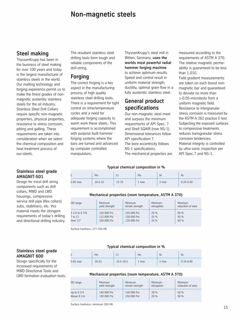
Non-magnetic steels
Steel makingThyssenKrupp has been in the business of steel making for over 100 years and today is the largest manufacturer of stainless steels in the world. Our melting technology and forging experience permit us to make the finest grades of non-magnetic austenitic stainless steels for the oil industry.Stainless Steel Drill Collars require specific non-magnetic properties, physical properties, resistance to stress corrosion, pitting and galling. These requirements are taken into con sideration when we select the chemical composition and heat treatment process of our-steels.
The resultant stainless steel drilling tools form tough and reliable components of the drill-string.
ForgingThe correct forging is a key aspect in the manufacturing process of high quality stainless steel drilling tools.There is a requirement for tight control on time/temperature cycles and a need for adequate forging capacity to warm work these steels. This requirement is accomplished with purpose built hammer forging systems where the bars are turned and advanced by computer controlled manipulators.
ThyssenKrupp’s steel mill in Witten, Germany, uses the worlds most powerful radial hammer forging machine to achieve optimum results. Speed and control result in uniform material strength, ductility, optimal grain flow in a fully austenitic stainless steel.
General product specificationsOur non-magnetic steel meet and surpass the minimum requirements of API Spec. 7 and Shell SQAIR (now NS-1).Dimensional tolerances follow API specification 7.The bore eccentricity follows NS-1 specifications.The mechanical properties are
measured according to the requirements of ASTM A 370.The relative magnetic perme-ability is guaranteed to be less than 1.010.Field gradient measurements are taken on each bored non-magnetic bar and guaranteed to deviate no more than ±-0.05-microtesla from a uniform magnetic field.Resistance to intergranular stress corrosion is measured by the ASTM A 262 practice E test.Subjecting the exposed surfaces to compressive treatments reduces transgranular stress corrosion tendencies.Material integrity is controlled by ultra-sonic inspection per API Spec.7 and NS-1.
Stainless steel grade AMAGNIT-501Design for most drill string components such as drill collars, MWD and LWD housings, compressive service drill pipe (flex collars) subs, stabilisers, etc. this material meets the stringent requirements of today’s drilling and directional drilling industry.
Surface hardness: 277-350 HB
Stainless steel grade AMAGNIT 600Design specifically for the increased requirements of MWD Directional Tools and LWD formation evaluation tools.
Typical chemical composition in %
C Mn Cr Mo Ni N2
0.05 max 18.5-22 13-15 1 max 2 max 0.25-0.50
Mechanical properties (room temperature, ASTM A 370)
OD range Minimum Minimum Minimum Minimum yield strength tensile strength elongation reduction of area
3 1/2 to 6 7/8 120 000 Psi 135 000 Psi 25 % 50 %7 to 11 112 000 Psi 130 000 Psi 25 % 50 %Over 11" 100 000 Psi 120 000 Psi 25 % 50 %
Surface hardness: minimum 300 HB
Typical chemical composition in %
C Mn Cr Mo Ni N2
0.05 max 18-22 16.5-19.5 1 max 2 max 0.45-0.80
Mechanical properties (room temperature, ASTM A 370)
OD range Minimum Minimum Minimum Minimum yield strength tensile strength elongation reduction of area
Up to 9 1/4 140 000 Psi 150 000 Psi 20 % 50 %Above 9 1/4 130 000 Psi 150 000 Psi 20 % 50 %
CC2004 ThyssenKrupp.indd 15CC2004 ThyssenKrupp.indd 15 7/22/04 12:39:37 PM7/22/04 12:39:37 PM

G 3
0 71
/3 -
Jan
uary
200
3 M
V Ed
ition
Com
posi
tion
02 4
3 87
00
89
ThyssenKrupp Materials FranceR.C. Versailles B 562 068 155
Worldwide Stock Points
North Sea Aberdeen
Gulf Coast Houston
Canada Edmonton
Europe Dunkirk
Middle East Dubai
India Mumbai
Far East Singapore
ThyssenKrupp Materials France
Z.A. Pariwest - B.P. 52 - 6, Avenue Gutenberg - 78311 MAUREPAS Cedex - FRANCE☎ +33 1 30 69 67 02 / +33 1 30 69 55 04 - Fax : +33 1 30 69 55 07
For assistance on any product, please call or e-mail: [email protected]
CC2004 ThyssenKrupp.indd 16CC2004 ThyssenKrupp.indd 16 7/22/04 12:39:38 PM7/22/04 12:39:38 PM