sinalização de canal comum
TRANSCRIPT

Sinalização de Canal Comum
1
2
ObjetivosDepois desta sessão de treinamento, o participante deverá estar apto a:
Explicar sem consultas a referências ou a qualquer nota, o que é sinalização e listar os diferentes tipos de sinalização.
Desenhar uma figura do stack do protocolo CCS7 presente em um MSCi DX 200 sem referência a nenhuma nota.
Listar quais dos protocolos desenhados anteriormente são necessários para os seguintes elementos de rede: PSTN, HLR, BSC, NMS-FE
Listar as unidades de sinalização usadas para CCS7 .
Explicar os significado das seguintes abreviaturas e também para que são usadas: SP, OP, DP, SEP, STP; SPC, OPC, DPC, SL, SLN, SLC; SLS, SR, SRS; CIC; NA0, NA1, IN0, IN1
Liste os passos para criar a rede de sinalização nível MTP com referência somente à lista feita pelo parágrafo anterior, dos objetivos.
3
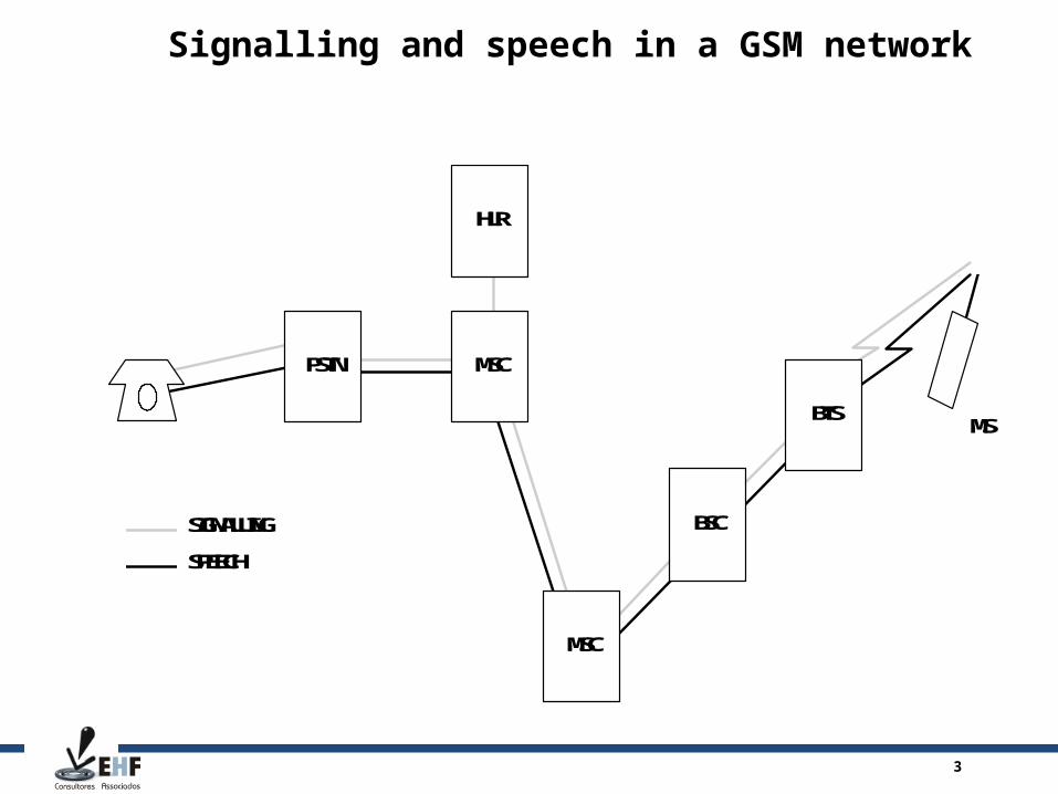
MSC
MSC
HLR
PSTN
BSC
BTSMS
SIGNALLING
SPEECH
Signalling and speech in a GSM network
4
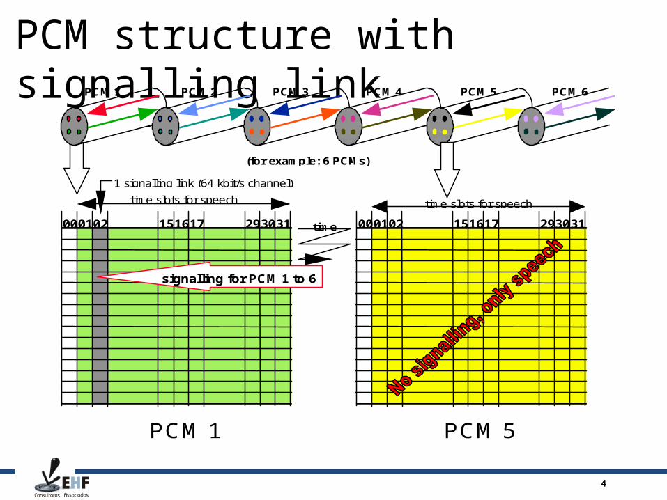
PCM structure with signalling link
D O C U M E N T T Y P E
T y p e U n i t O r D e p a r t m e n t H e r eT y p e Y o u r N a m e H e r e T y p e D a t e H e r e
P C M 5
0 0 0 1 0 2 1 5 1 6 1 7 2 9 3 0 3 1
P C M 1
0 0 0 1 0 2 1 5 1 6 1 7 2 9 3 0 3 1
s i g n a l l i n g f o r P C M 1 t o 6
P C M 1 P C M 2 P C M 3 P C M 4 P C M 5 P C M 6
t i m e s l o t s f o r s p e e c h
( f o r e x a m p l e : 6 P C M s )
1 s i g n a l l i n g l i n k ( 6 4 k b i t / s c h a n n e l )
t i m e
t i m e s l o t s f o r s p e e c h
5
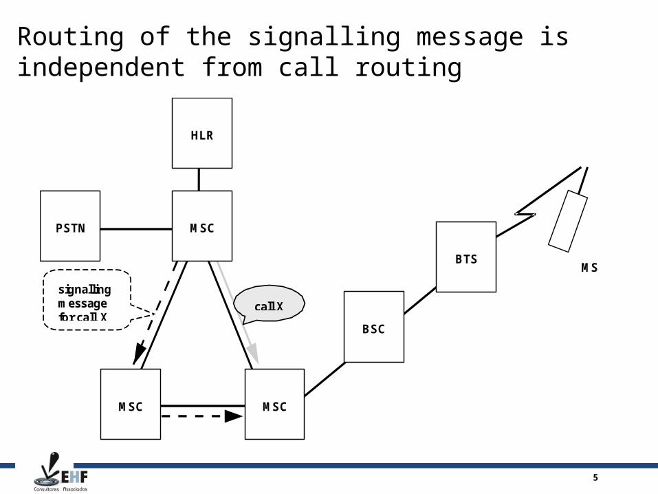
Routing of the signalling message is independent from call routing
D O C U M E N T T Y P E
T y p e U n i t O r D e p a r t m e n t H e r eT y p e Y o u r N a m e H e r e T y p e D a t e H e r e
M S C
M S C
H L R
P S T N
B S C
B T SM S
M S C
c a l l X
s i g n a l l i n gm e s s a g ef o r c a l l X

6
Differences between CAS and CCS7CAS CCS7
One time slot for signalling in each PCM. None, one or more signalling time slots per PCM.
Signalling always in time slot 16. Signalling in any time slot, except TSL 0.
One signalling time slot per 30 speech connections of the same PCM.
One signalling time slot per about 500 - 1000 speech connections of any PCM.
Circuit-related signalling sent at certain moment is associated to a fixed speech TSL in the same PCM.
Circuit-related signalling is associated to a speech connection of any PCM and is sent only when needed.
Non-circuit related signalling impossible. Non-circuit related signalling possible.
No message structure, no error detection and correction, fixed bit patterns.
Standardised message structure with error detection and correction.
No identification of sender and receiver other than time of sending and PCM, thus no call independent routing.
Identification of sender, receiver and circuit within the message allows call independent routing.
4 bits per signalling pattern. Variable message length up to several hundred octets.
Continuously equal quantity of signalling per each speech connection.
Signalling only when needed and then with full capacity of the whole signalling link.

7
The OSI reference model and CCS7
1 Physical layer
2 Data link layer
3 Network layer
4 Transport layer
5 Session layer
6 Presentation layer
7 Application layer
MTP (levels 1-3)
User Part (level 4)
OSI Reference ModelCCITT Common
Channel SignallingNo 7
8
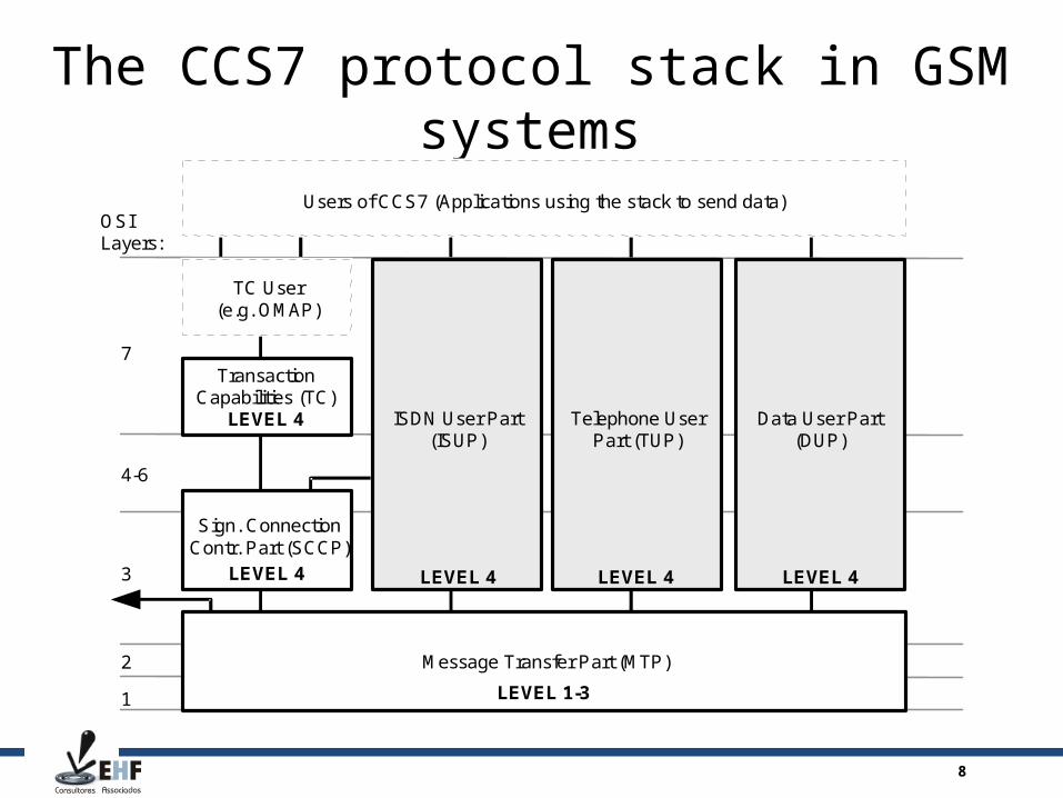
The CCS7 protocol stack in GSM systems
Users of CCS7 (Applications using the stack to send data)
Message Transfer Part (MTP)
TC User(e.g. OMAP)
TransactionCapabilities (TC)
Sign. ConnectionContr. Part (SCCP)
LEVEL 4
ISDN User Part(ISUP)
Telephone UserPart (TUP)
Data User Part(DUP)
OSILayers:
7
4-6
3
2
1
LEVEL 4 LEVEL 4 LEVEL 4
LEVEL 1-3
LEVEL 4
9
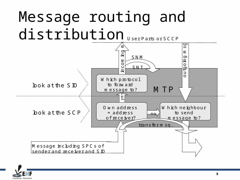
Message routing and distribution
D O C U M E N T T Y P E
T y p e U n i t O r D e p a r t m e n t H e r eT y p e Y o u r N a m e H e r e T y p e D a t e H e r e
l o o k a t t h e S C P
l o o k a t t h e S I O
O w n a d d r e s s= a d d r e s s
o f r e c e i v e r ?
W h i c h p r o t o c o lt o f o r w a r d
m e s s a g e t o ?
W h i c h n e i g h b o u rt o s e n d
m e s s a g e t o ?n o
M T P
inc
om
ing
ms
g.
S N M
S N T
t r a n s f e r m s g .
U s e r P a r t s o r S C C P
ye
s
ou
tgo
ing
ms
g.
M e s s a g e i n c l u d i n g S P C s o fs e n d e r a n d r e c e i v e r a n d S I O
10
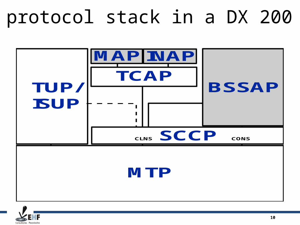
The protocol stack in a DX 200 MSC
MTP
SCCP
TCAPBSSAPTUP/
ISUP
MAP INAP
CLNS CONS

11
Signalling terminalsPlug-in Unit handles ... signalling links Pre-processor
AS7-S 1 10 MHz, 80186
AS7-U 4 20 MHz, 80286
AS7-V 16 33 MHz, 80486
AS7-A 16 133 MHz, 486DX5
12
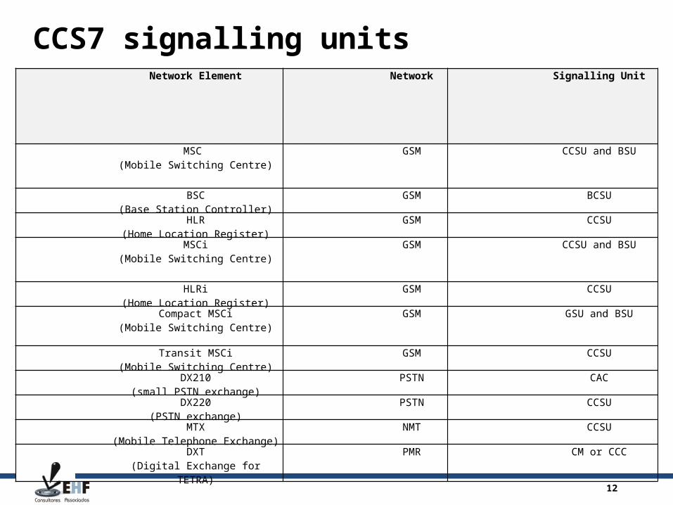
CCS7 signalling unitsNetwork Element Network Signalling Unit
MSC (Mobile Switching Centre)
GSM CCSU and BSU
BSC(Base Station Controller)
GSM BCSU
HLR(Home Location Register)
GSM CCSU
MSCi(Mobile Switching Centre)
GSM CCSU and BSU
HLRi(Home Location Register)
GSM CCSU
Compact MSCi(Mobile Switching Centre)
GSM GSU and BSU
Transit MSCi(Mobile Switching Centre)
GSM CCSU
DX210(small PSTN exchange)
PSTN CAC
DX220(PSTN exchange)
PSTN CCSU
MTX(Mobile Telephone Exchange)
NMT CCSU
DXT(Digital Exchange for TETRA)
PMR CM or CCC

13
CCSU (or BSU) with two AS7-U signalling terminals
D O C U M E N T T Y P E
T y p e U n i t O r D e p a r t m e n t H e r eT y p e Y o u r N a m e H e r e T y p e D a t e H e r e
AS
7-U
0
AS
7-U
1
CP
486
MB
IF-T
1
MB
0
MB
1M
B1
MB
0
9 28 78 27 77 25 75 24 74 23 73 22 72 21 71 20 70 2 6 2 9 7
MB
IF-T
0
AF
S-S
6 7
C C S R - S

14
CCSU equipment in a CC3C-A cartridge
OPR
C4314
DP
CM
C4
31
4GH
JK
L87
451
24
53
WO
RUN
LF
OL
ETx
ERx
SB
CPCI
AP
TE
DRAM
SCSI
C4314
CP
52
3-A
C4
31
4GH
JK
L87
451
24
53
DBG
RST
J6
J7
OPR
C4314
PS
C6
-AC
43
14G
HJ
KL87
451
24
53
ON
OFF
OPR
C4314
DP
CM
C4
31
4GH
JK
L87
451
24
53
C4314
DP
CM
C4
31
4GH
JK
L87
451
24
53
AP
C4314
DP
CM
C4
31
4GH
JK
L87
451
24
53
AP
C4314
DP
CM
C4
31
4GH
JK
L 87
451
24
53
APAS
7 0
AS
7 1
AS
7 2
CP
U
PS
C6
MB
IF 1
MB
IF 0
21 3 4 5 6 7 8 9 10
15
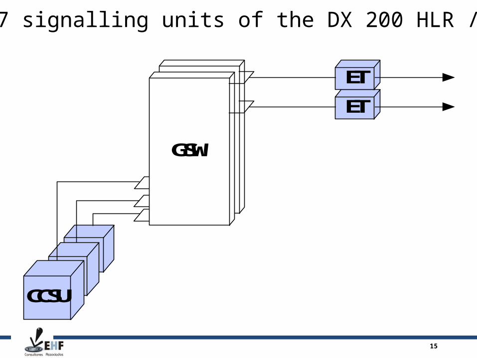
The CCS7 signalling units of the DX 200 HLR / HLRi
GSW
CCSU
ET
ET
16
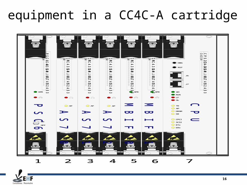
BSU equipment in a CC4C-A cartridge
OPR
C4314
DP
CMC
43
14
GH
JK
L8
74
512
45
3 WO
RUN
LF
OL
ETx
ERx
SB
CPCI
AP
TE
DRAM
SCSI
C4314
CP
52
3-A
C4
31
4G
HJ
KL
87
4512
45
3
DBG
RST
J6
J7
OPR
C4314
PS
C6
-A
C4
31
4G
HJ
KL
87
4512
45
3
ON
OFF
OPR
C4314
DP
CMC
43
14
GH
JK
L8
74
512
45
3
C4314
DP
CMC
43
14
GH
JK
L8
74
512
45
3
AP
C4314
DP
CMC
43
14
GH
JK
L8
74
512
45
3
AP
C4314
DP
CMC
43
14
GH
JK
L8
74
512
45
3
AP
AS
7 0
AS
7 1
AS
7 2
CP
U
PS
C6
MB
IF
1
MB
IF
0
21 3 4 5 6 7
17
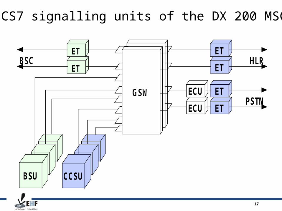
The CCS7 signalling units of the DX 200 MSC/VLR
ECUGSW
CCSUBSU
ET
ET
ETHLR
PSTN
BSCET
ECU ET
ET
18
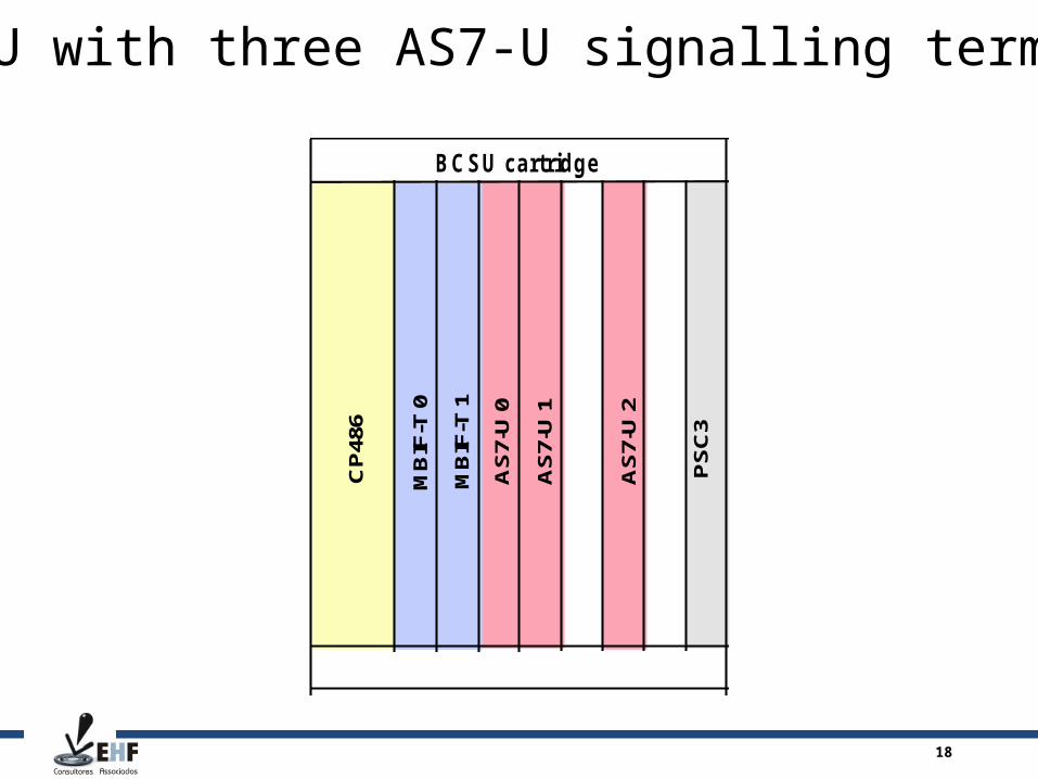
BCSU with three AS7-U signalling terminals
MB
IF-T
0
MB
IF-T
1
AS
7-U
0
AS
7-U
1
AS
7-U
2
CP
486
BCSU cartridge
PS
C3

19
The CCS7 signalling units of the DX 200 BSC
D O C U M E N T T Y P E
T y p e U n i t O r D e p a r t m e n t H e r eT y p e Y o u r N a m e H e r e T y p e D a t e H e r e
E T
G S W
B T SM S CE TE T
B C S U

20
The CCMU in a MCWR subrack can be found in bigger MSCs
CH
4HX/
CP4
HL
or C
P4C
32
MB
IF-T
/U 1
MB
0
MB
1
MB
1
MB
0
92 87 82 77 72 57 52 47 42 37 32 27 22 17 12 07 02 62 97
MB
IF-T
/U 0
67
MCWR-S

21
Signalling Point types
SEP STP SEP
22
Circuit-related signalling message
OPC
DPC
SIO
CIC
.....
23
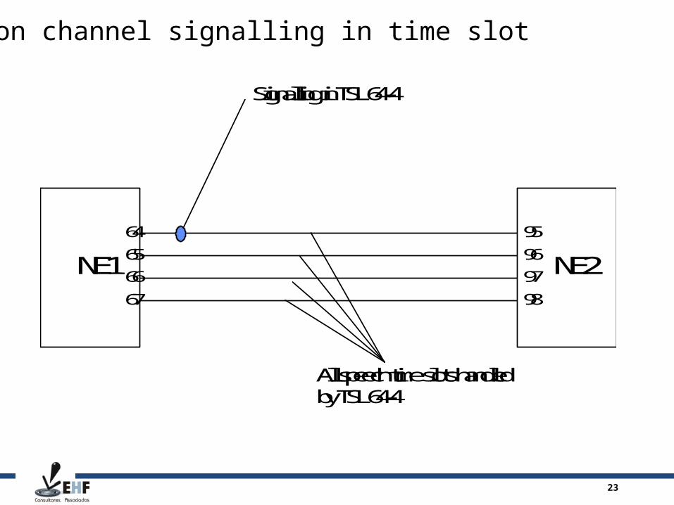
Common channel signalling in time slot
NE1 NE2
Signalling in TSL 64-4
65
66
64
67
All speech time slots handledby TSL 64-4
96
97
95
98

24
Signalling link definitions in an MSC
<ZNCI;DX 200 MSC03 1998-09-13 09:30:45INTERROGATING SIGNALLING LINK DATA TERM LOG LOG PARAM LINK LINK SET PCM-TSL UNIT TERM FUNCT UNIT TERM SET ---- --------- -------- ------------------ ---------- ----- 0 16 HLR01 88-01 CCSU-2 1 0 4041H 1 0 1 16 HLR01 90-01 CCSU-0 3 0 4042H 0 0 2 17 BSC01 80-16 BSU-2 1 0 4131H 1 0 3 18 PSTN1 65-01 CCSU-2 0 0 4041H 0 0 4 19 BSC02 81-16 BSU-1 1 0 4132H 0 0 5 20 PSTN2 66-01 CCSU-2 2 0 4041H 2 0COMMAND EXECUTED
25
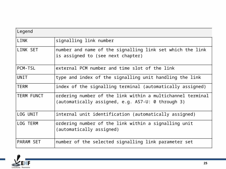
Legend
LINK signalling link number
LINK SET number and name of the signalling link set which the link is assigned to (see next chapter)
PCM-TSL external PCM number and time slot of the link
UNIT type and index of the signalling unit handling the link
TERM index of the signalling terminal (automatically assigned)
TERM FUNCT ordering number of the link within a multichannel terminal (automatically assigned, e.g. AS7-U: 0 through 3)
LOG UNIT internal unit identification (automatically assigned)
LOG TERM ordering number of the link within a signalling unit (automatically assigned)
PARAM SET number of the selected signalling link parameter set
26
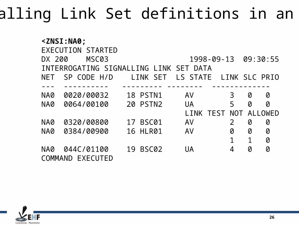
Signalling Link Set definitions in an MSC
<ZNSI:NA0;EXECUTION STARTEDDX 200 MSC03 1998-09-13 09:30:55INTERROGATING SIGNALLING LINK SET DATANET SP CODE H/D LINK SET LS STATE LINK SLC PRIO --- ---------- --------- -------- ------------- NA0 0020/00032 18 PSTN1 AV 3 0 0 NA0 0064/00100 20 PSTN2 UA 5 0 0 LINK TEST NOT ALLOWEDNA0 0320/00800 17 BSC01 AV 2 0 0 NA0 0384/00900 16 HLR01 AV 0 0 0 1 1 0 NA0 044C/01100 19 BSC02 UA 4 0 0 COMMAND EXECUTED
27
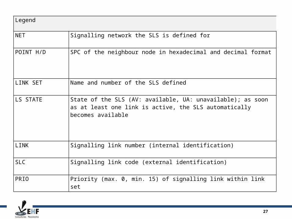
Legend
NET Signalling network the SLS is defined for
POINT H/D SPC of the neighbour node in hexadecimal and decimal format
LINK SET Name and number of the SLS defined
LS STATE State of the SLS (AV: available, UA: unavailable); as soon as at least one link is active, the SLS automatically becomes available
LINK Signalling link number (internal identification)
SLC Signalling link code (external identification)
PRIO Priority (max. 0, min. 15) of signalling link within link set
28
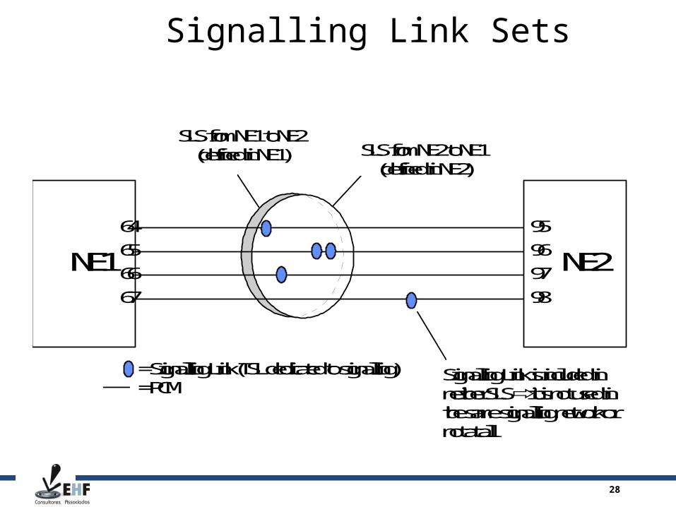
Signalling Link Sets
NE1 NE265
66
64
67
= Signalling Link (TSL dedicated to signalling)= PCM
SLS from NE2 to NE1(defined in NE2)
SLS from NE1 to NE2(defined in NE1)
Signalling Link is included inneither SLS it is not used inthe same signalling network ornot at all
96
97
95
98
29
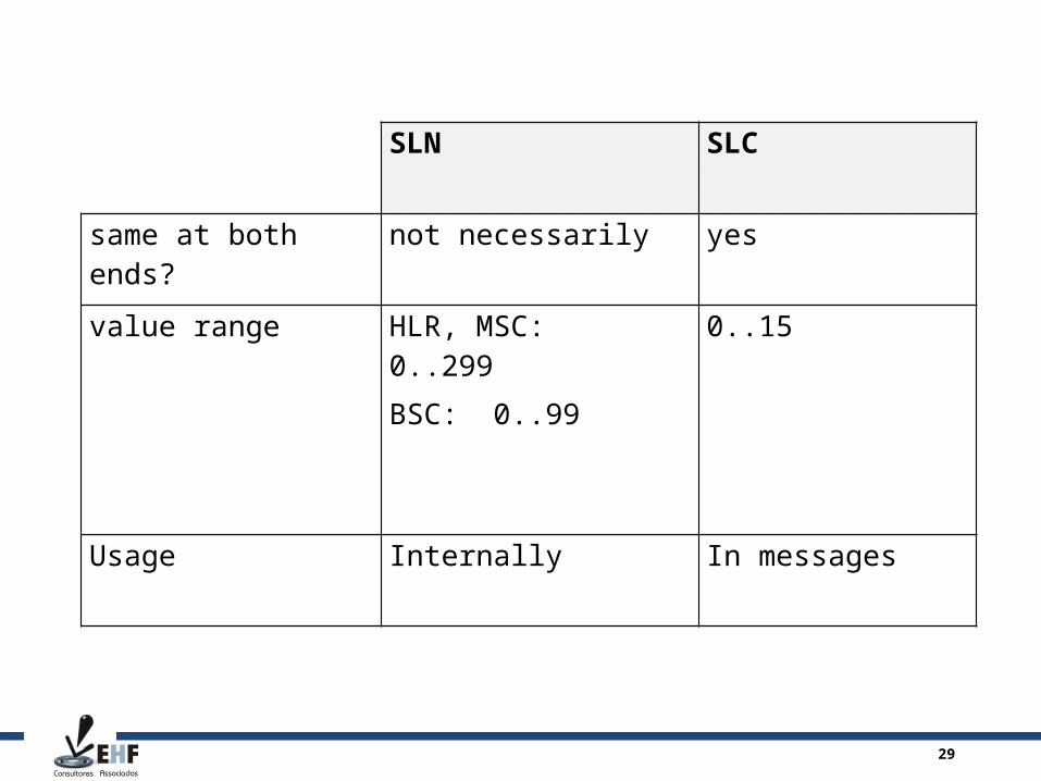
SLN SLC
same at both ends? not necessarily yes
value range HLR, MSC: 0..299
BSC: 0..99
0..15
Usage Internally In messages

30
Signalling Route (SR) and Signalling Route Set (SRS)
OP
SRS containing all possible routes (neighbours) to reach DP from OP (as defined in OP)
SLS from OP to DP(as defined in OP)
SLS from OP to STP(as defined in OP)
DP
STP

31
<ZNRI:NA0;DX 200 MSC03 1998-09-13 09:31:05INTERROGATING SIGNALLING POINT DATANET SP CODE H/D NAME RS STATE PAR SET--- ------------ ------- -------- ---------NA0 0020/00032 PSTN1 AV 0LOAD SHARING BETWEEN SIGNALLING ROUTES DENIEDROUTES: SP CODE H/D NAME STATE PRIO --------------- ---- ------ ---- NA0 0020/00032 PSTN1 AV-EX 7 NA0 0064/00100 PSTN2 AV-SP 6NET SP CODE H/D NAME RS STATE PAR SET--- ------------ ------- -------- ---------NA0 0064/00100 PSTN2 AV 0 LOAD SHARING BETWEEN SIGNALLING ROUTES DENIEDROUTES: SP CODE H/D NAME STATE PRIO --------------- ---- ------ ---- NA0 0064/00100 PSTN2 AV-EX 7 NA0 0020/00032 PSTN1 AV-SP 6NET SP CODE H/D NAME RS STATE PAR SET--- ------------ ------- -------- ---------NA0 0320/00800 BSC01 AV 1 LOAD SHARING BETWEEN SIGNALLING ROUTES DENIEDROUTES: SP CODE H/D NAME STATE PRIO --------------- ---- ------ ---- NA0 0320/00800 BSC01 AV-EX 0
Signalling Route Set definitions in an MSC
32
Legend
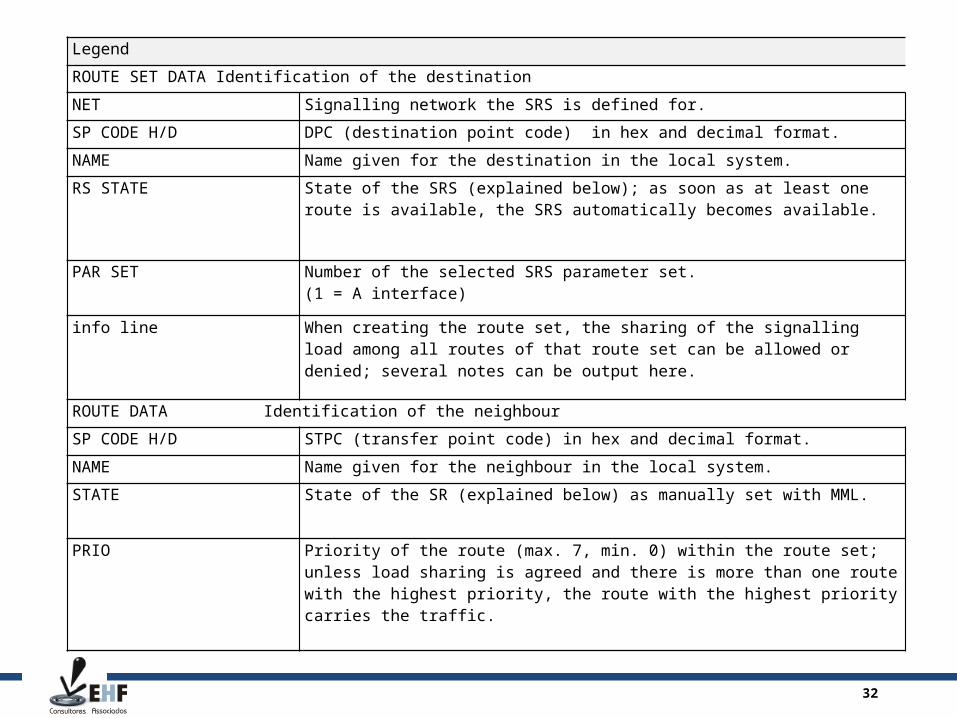
ROUTE SET DATA Identification of the destination
NET Signalling network the SRS is defined for.
SP CODE H/D DPC (destination point code) in hex and decimal format.
NAME Name given for the destination in the local system.
RS STATE State of the SRS (explained below); as soon as at least one route is available, the SRS automatically becomes available.
PAR SET Number of the selected SRS parameter set.(1 = A interface)
info line When creating the route set, the sharing of the signalling load among all routes of that route set can be allowed or denied; several notes can be output here.
ROUTE DATA Identification of the neighbour
SP CODE H/D STPC (transfer point code) in hex and decimal format.
NAME Name given for the neighbour in the local system.
STATE State of the SR (explained below) as manually set with MML.
PRIO Priority of the route (max. 7, min. 0) within the route set; unless load sharing is agreed and there is more than one route with the highest priority, the route with the highest priority carries the traffic.

33
Legend (cont.)
POINT DATA Identification of the own signalling point
NET Signalling network the own SP is defined in.
SP CODE H/D Own SPC in hex and decimal format.
SP NAME Own name as given locally.
SP TYPE Indicates if the own SP is created as an end point (SEP) or a transfer point (STP).
SS7 STAND Indicates the used signalling standard: mainly if the SPC is composed according to CCITT rules (14bit SPC), ANSI or CHINA standards (both 24 bit SPC).
SUBFIELD INFO Tells about the grouping of the SPC bits into max 3 groups (subfields) and how many bits per subgroup are allocated.

34
National signalling networks (NA0 and NA1)
operator A
operator B
operator C100
SPC in NA0
100
110250
120 260
270290
280301
300
302NA0
CountryA
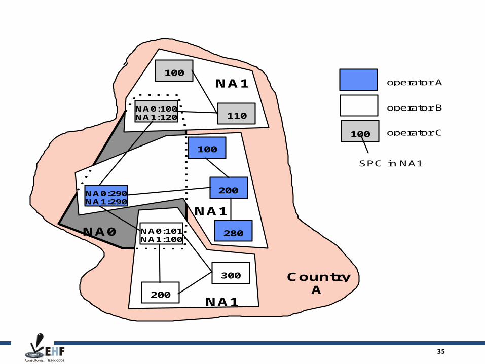
35
D O C U M E N T T Y P E
T y p e U n i t O r D e p a r t m e n t H e r eT y p e Y o u r N a m e H e r e T y p e D a t e H e r e
o p e r a t o r A
o p e r a t o r B
o p e r a t o r C1 0 0
S P C i n N A 1
1 0 0
1 1 0N A 0 : 1 0 0N A 1 : 1 2 0
1 0 0
2 0 0
2 8 0
3 0 0
2 0 0N A 1
C o u n t r yA
N A 1
N A 1
N A 0
N A 0 : 2 9 0N A 1 : 2 9 0
N A 0 : 1 0 1N A 1 : 1 0 0
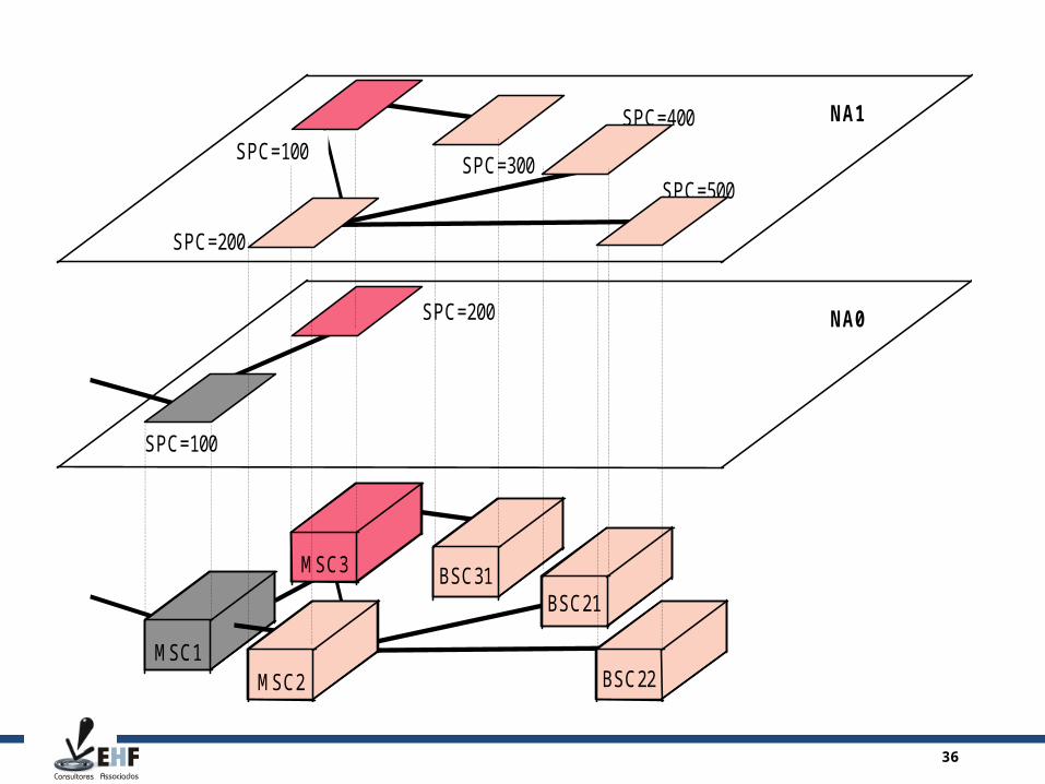
36
D O C U M E N T T Y P E
T y p e U n i t O r D e p a r t m e n t H e r eT y p e Y o u r N a m e H e r e T y p e D a t e H e r e
N A 1
N A 0
S P C = 1 0 0
S P C = 2 0 0
S P C = 2 0 0
S P C = 3 0 0
S P C = 4 0 0
S P C = 5 0 0
B S C 2 1B S C 3 1M S C 3
M S C 1M S C 2
S P C = 1 0 0
B S C 2 2
37
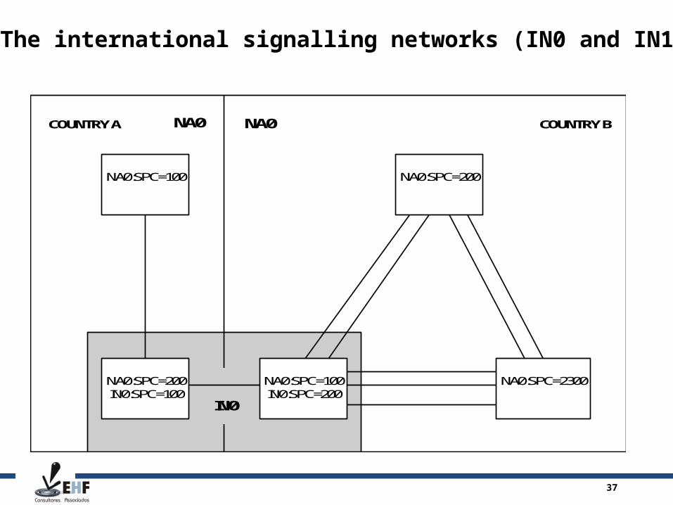
The international signalling networks (IN0 and IN1)
NA0:SPC=200IN0:SPC=100
NA0:SPC=2300
NA0:SPC=200
NA0:SPC=100IN0:SPC=200
NA0:SPC=100
NA0
IN0
COUNTRY BCOUNTRY A NA0

38
Signalling Link States and Substates
AV-EX - Available-executing -Link is working normally.UA-AD - Unavailable-activation denied -Operator has taken the link out of use and has denied the activation.UA-TST - Unavailable-testingUser has started a data link test and only test traffic can be transferred by the link, while no signalling traffic is allowed.UA-INU - Unavailable-deactivated by userOperator has taken the link out of use. To activate the link use command NLC.UA-INS - Unavailable-deactivated by systemSystem has taken the link out of use. Link has not completed the initial alignment or the signalling link test procedure successfully.UA-BLU - Unavailable-blocked by userUser has blocked the signalling link.UA-BLR - Unavailable-blocked by remote exchangeRemote end exchange has blocked the signalling link, or there is a processor outage condition at remote end. UA-BLB - Unavailable-blocked by user and remote exchangeThe signalling link has been blocked at both ends.
39
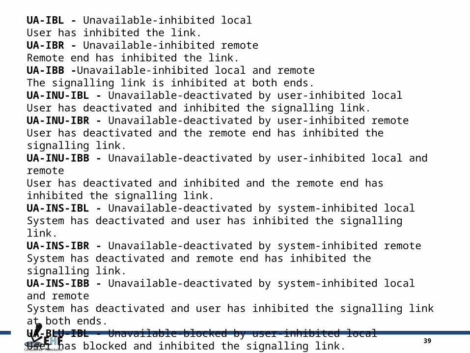
UA-IBL - Unavailable-inhibited localUser has inhibited the link.UA-IBR - Unavailable-inhibited remoteRemote end has inhibited the link.UA-IBB -Unavailable-inhibited local and remoteThe signalling link is inhibited at both ends.UA-INU-IBL - Unavailable-deactivated by user-inhibited localUser has deactivated and inhibited the signalling link.UA-INU-IBR - Unavailable-deactivated by user-inhibited remoteUser has deactivated and the remote end has inhibited the signalling link.UA-INU-IBB - Unavailable-deactivated by user-inhibited local and remoteUser has deactivated and inhibited and the remote end has inhibited the signalling link.UA-INS-IBL - Unavailable-deactivated by system-inhibited localSystem has deactivated and user has inhibited the signalling link.UA-INS-IBR - Unavailable-deactivated by system-inhibited remoteSystem has deactivated and remote end has inhibited the signalling link.UA-INS-IBB - Unavailable-deactivated by system-inhibited local and remoteSystem has deactivated and user has inhibited the signalling link at both ends.UA-BLU-IBL - Unavailable-blocked by user-inhibited localUser has blocked and inhibited the signalling link.UA-BLU-IBR - Unavailable-blocked by user-inhibited remoteUser has blocked and remote end has inhibited the signalling link.UA-BLU-IBB - Unavailable-blocked by user-inhibited local and remoteUser has blocked the signalling link and the signalling link is inhibited at both ends.
40
UA-BLR-IBL - Unavailable-blocked by remote exchange-inhibited localThe signalling link is blocked at remote end and user has inhibited the signalling link.UA-BLR-IBR - Unavailable-blocked by remote exchange-inhibited remoteThe signalling link is blocked and inhibited at remote end.UA-BLR-IBB - Unavailable-blocked by remote exchange-inhibited local and remoteThe signalling link is blocked at remote end and inhibited by user at both ends.UA-BLB-IBL - Unavailable-blocked by user and remote exchange-inhibited localUser has blocked and inhibited the signalling link and the remote end has blocked the signalling link.UA-BLB-IBR - Unavailable-blocked by user and remote exchange-inhibited remoteUser has blocked the signalling link and the signalling link is blocked and inhibited at remote end.UA-BLB-IBB - Unavailable-blocked by user and remote exchange-inhibited local and remoteThe signalling link is blocked and inhibited at both ends.
41
Signalling Route States and Substates
AV-EX - Available-executingThe signalling route is transferring signalling traffic.AV-SP - Available-spareThe signalling route does not transfer signalling traffic but can be taken into use.UA-INU - Unavailable-deactivated by userUser has deactivated the route.UA-INS - Unavailable-deactivated by systemThe system has deactivated the route.UA-INR - Unavailable-deactivated by remote exchangeThe remote end has deactivated the route.UA-AD - Unavailable-activation deniedActivation of the route is denied.AR-EX - Available but restricted-executingThe signalling route has received a "transfer restricted" message from the transfer point, which lowers the priority of the route.AR-SP - Available but restricted-spareSame as above for a spare route.