murelle equipe 220-550 box erp -es - simehellas.gr
TRANSCRIPT

MURELLE EQUIPE 220-330-440-550 BOX ErP
Fonderie SIME S.p.A Cod. 6322825 - 03/2016
ES
ENG


PARA EL INSTALADOR
ÍNDICE
1 DESCRIPCIÓN DEL APARATO . . . . . . . . . . . . . . . . . . . . . . . . . . . . . . . . . . . . . . . . . . . . . . . . . . . . . . . . . . . . . . . . . .pág. 4
2 INSTALACIÓN . . . . . . . . . . . . . . . . . . . . . . . . . . . . . . . . . . . . . . . . . . . . . . . . . . . . . . . . . . . . . . . . . . . . . . . . . . . . . . . . .pág. 10
3 CARACTERÍSTICAS . . . . . . . . . . . . . . . . . . . . . . . . . . . . . . . . . . . . . . . . . . . . . . . . . . . . . . . . . . . . . . . . . . . . . . . . . . . .pág. 22
4 USO Y MANTENIMIENTO . . . . . . . . . . . . . . . . . . . . . . . . . . . . . . . . . . . . . . . . . . . . . . . . . . . . . . . . . . . . . . . . . . . . . .pág. 29
IMPORTANTE
Al efectuar el primer encendido de la caldera es buena norma efectuar las siguientes comprobaciones:
– Comprobar que no haya líquidos o materiales inflamables en las inmediatas cercanías de la caldera.
– Comprobar que el conexionado eléctrico haya sido efectuado correctamente y que el cable de tierra esté
conectado con una buena instalación de tierra.
– Abrir el grifo del gas y comprobar que sean herméticos los empalmes, incluido él del quemador.
– Comprobar que la caldera esté predispuesta para funcionar con el tipo de gas disponible.
– Comprobar que el conducto de evacuación de los productos de la combustión esté libre y/o esté monta-
do correctamente.
– Comprobar que las eventuales válvulas de compuerta estén abiertas.
– Comprobar que la instalación esté llena de agua y que esté bien purgada.
– Comprobar que el circulador no esté bloqueado
– Purgar el aire presente en la tubería del gas actuando sobre el purgador de toma de presión situado en
la entrada de la válvula del gas.
La FONDERIE SIME S.p.A. afincada en Via Garbo 27 - Legnago (VR) – Italy, declara que sus calderas de aguacaliente, marcadas CE conforme a la Directiva Gas 90/396/CEE y equipadas con termostato de seguridad aju-stado para un máximo de 110°C, están excluidas del campo de aplicación de la Directiva PED 97/23/CEE ya quecumplen los requisitos previstos en el artículo 1 apartado 3.6 de dicha directiva.
MU
REL
LE E
QU
IPE
22
0-3
30
-44
0-5
50
BO
X E
rP -
ESP
AÑ
OL
CONFORMIDAD
Nuestra Compañia declara que las calderas MURELLE EQUIPE 220-330-440-550 BOX ErP son conformes a losrequisitos esenciales de las siguientes directivas:- Directiva Eficiencia 92/42/CEE- Directiva Gas 2009/142/CE- Directiva Compatibilidad Electromagnética 2004/108/CE- Directiva Baja Tensión 2006/95/CE- Diseño Ecológico Directiva 2009/125/CE- Reglamento (UE) N. 813/2013 - 811/2013

4
1.1 INTRODUCCIÓN
Los módulos térmicos “MURELLE EQUIPE220-330-440-550 BOX ErP” son aparatos
de condensación premezclados, destinadossólo a la calefacción, son acoplables entreellos y fácilmente ensamblables, predispue-stos para el funcionamiento individual o en
secuencia/cascada independientes unorespecto a otro.
1 DESCRIPCIÓN DEL APARATO
1.2 DIMENSIONES MÓDULOS
1.2.1 “MURELLE EQUIPE 220 BOX ErP” (fig. 1)
CONEXIONESM Ida instalación (Brida PN6-DN100)R Retorno instalación (Brida PN6-DN100)G Gas (Brida PN6-DN50)S3 Descarga agua de condensación ø 40
Fig. 1
90
180
156396
790
567
272
S3
G
M
307
777
R
260380 1100
648
1600
2010
470 390
NOTA: Es obligatorio montar un separador hidráulico o intercambiador de placas. El separador hidráulico se suministra bajopedido en el kit cód. 8101552 y los tubos de conexión del separador hidráulico en el kit cód. 8101532. El montaje del sepa-rador hidráulico está previsto del lado izquierdo, todavía existe la posibilidad de montarlo del lado derecho desplazando lasbridas ciegos de los colectores impulsión/retorno de la instalación.

5
ES
ENG
1.2.2 “MURELLE EQUIPE 330 BOX ErP” (fig. 1/a)
90
180
156396
790
567
272
S3
G
Q
648
1600
2010
390630470
1730380 260
307
777
M
R
1100 630
Fig. 1/a
CONEXIONESM Ida instalación (Brida PN6-DN100)R Retorno instalación (Brida PN6-DN100)G Gas (Brida PN6-DN50)S3 Descarga agua de condensación ø 40
NOTA: Es obligatorio montar un separador hidráulico o intercambiador de placas. El separador hidráulico se suministra bajopedido en el kit cód. 8101552 y los tubos de conexión del separador hidráulico en el kit cód. 8101532. El montaje del sepa-rador hidráulico está previsto del lado izquierdo, todavía existe la posibilidad de montarlo del lado derecho desplazando lasbridas ciegos de los colectores impulsión/retorno de la instalación.

6
1.2.3 “MURELLE EQUIPE 440-550 BOX ErP” (fig. 1/b)
180
790396
156
567
90
272 56
2
1197
S3
M
R
G
1600
2010
2830590500
390630470630470
635
562
MURELLE EQUIPE 440 BOX ErP
180
790396
156
567
90
272 56
2
1197
S3
M
R
G
1600
2010
2200590500
390470630470
635
562
MURELLE EQUIPE 550 BOX ErP
Fig. 1/b
CONEXIONESM Ida instalación (Brida PN6-DN100)R Retorno instalación (Brida PN6-DN100)G Gas (Brida PN6-DN50)S3 Descarga agua de condensación ø 40
NOTA: Es obligatorio montar un separador hidráulico o intercambiador de placas. El separador hidráulico se suministra bajopedido en el kit cód. 8101553 y los tubos de conexión del separador hidráulico en el kit cód. 8101533. El montaje del sepa-rador hidráulico está previsto del lado izquierdo, todavía existe la posibilidad de montarlo del lado derecho desplazando lasbridas ciegos de los colectores impulsión/retorno de la instalación.

7
ES
ENG
1.3 DATOS TÉCNICOS
MURELLE EQUIPE 220 BOX ErP 330 BOX ErP 440 BOX ErP 550 BOX ErP
Generadores con potencia térmica nominal 105,4 kW n° 2 3 4 5
Potencia térmica
Nominal (80-60°C) (Pn max) kW 210,8 316,2 421,6 527,0
Nominal (50-30°C) (Pn max) kW 225,2 337,8 454,0 563,0
Mínima (80-60°C) (Pn min) kW 20,8 20,8 20,8 20,8
Mínima (50-30°C) (Pn min) kW 23,2 23,2 23,2 23,2
Caudal térmico (*)
Nominal (Qn max - Qnw max) kW 216 324 432 540
Mínimo (Qn min - Qnw min) kW 21,6 21,6 21,6 21,6
Rendimiento útil mín/máx (80-60°C) % 96,4 / 97,6 96,4 / 97,6 96,4 / 97,6 96,4 / 97,6
Rendimiento útil mín/máx (50-30°C) % 107,4 / 104,2 107,4 / 104,2 107,4 / 104,2 107,4 / 104,2
Rendimiento útil al 30% (40-30°C) % 105,4 105,4 105,4 105,4
Pérdidas a la parada a 50°C (EN 15502) W 498 747 996 1245
Tensión de alimentación V-Hz 230-50 230-50 230-50 230-50
Potencia eléctrica absorbida (Qn max) W 516 774 1032 1290
Potencia eléctrica absorbida (Qn min) W 134 138 142 146
Potencia eléctrica absorbida bomba instalación W 260 (130 x 2) 390 (130 x 3) 520 (130 x 4) 650 (130 x 5)
Grado de protección eléctrica IPX4D IPX4D IPX4D IPX4D
Eficiencia energética
Clase de eficiencia energética estacional de calefacción A A A A
Eficiencia energética estacional de calefacción % 90 91 91 91
Potencia acústica de calefacción dB (A) --- --- --- ---
Regulación temperatura módulo individual °C 20/80 20/80 20/80 20/80
Contenido agua módulos l 36,3 55,9 72,6 92,2
Presión máxima de servicio (PMS) bar 5 5 5 5
Temperatura máxima de servicio (T max) °C 85 85 85 85
Temperatura humos a Q. Nominal (80-60°C) °C 64 64 64 64
Temperatura humos a Q. Mínima (80-60°C) °C 51 51 51 51
Temperatura humos a Q. Nominal (50-30°C) °C 45 45 45 45
Temperatura humos a Q. Mínima (50-30°C) °C 40 40 40 40
Caudal mínima/máximo humos g/s 10,28/103,34 10,28/155 10,28/206,67 10,28/258,34
CO2 a Q. Nominal/Mínima (G20) % 9,0/9,0 9,0/9,0 9,0/9,0 9,0/9,0
CO2 a Q. Nominal/Mínima (G31) % 10,2/10,2 10,2/10,2 10,2/10,2 10,2/10,2
NOx medidos mg/kWh 24 24 24 24
Presión máx de salida colector de humos Pa 375 375 375 375
Presión máx de salida de humos independiente Pa 428 428 428 428
Número PIN 1312CM5621 1312CM5621 1312CM5621 1312CM5621
Categoría II2H3P II2H3P II2H3P II2H3P
Categoría en Francia I2Er3P I2Er3P I2Er3P I2Er3P
Tipo B23-B53-B23P-B53P B23-B53-B23P-B53P B23-B53-B23P-B53P B23-B53-B23P-B53P
Clase NOx 5 5 5 5
Peso kg 380 615 760 995
Presiones gas y inyectores
Presión de alimentación (G20/G25) mbar 20/25 20/25 20/25 20/25
Presión de alimentación (G31) mbar 37 37 37 37
Cantidad inyectores n° 2 3 4 5
Diámetro inyectores (G20/G25) ø 12,4 12,4 12,4 12,4
Diámetro inyectores (G31) ø 8,2 8,2 8,2 8,2
Consumo a potencia nominal (G20) m3/h 22,84 34,26 45,68 57,10
Consumo a potencia mínima (G20) m3/h 2,28 2,28 2,28 2,28
Consumo a potencia nominal (G31) kg/h 16,76 25,14 33,52 41,90
Consumo a potencia mínima (G31) kg/h 1,68 1,68 1,68 1,68
(*) Caudal térmico de calefacción calculado utilizando el poder calorífico inferior (PCI)

8
M
R
1
2
3
19
20
721
25
23
22G
26
29
12
1614
15
18
2427
6
8
109
11
17S3
530
1.4 ESQUEMA FUNCIONAL (fig. 2)
Fig. 2
LEYENDA1 Sonda ida de cascada (SMC)2 Compensador hidráulico3 --------5 Sifón descarga agua de condensación6 Válvula gas7 --------8 Ventilador9 Sonda ida calefacción (SM)
10 Termostato seguridad 100°C11 Sonda humos (SF)12 Intercambiador primario14 Sonda retorno calefacción (SR)15 Transductor presión agua16 Válvula purga aire17 Válvula de retención18 Bomba instalación alta eficiencia
19 --------20 --------21 --------22 Grifo de descarga de tres vías23 Grifo ida instalación24 Descarga módulo individual25 Grifo gas26 Vaso expansión 8 litros27 Válvula seguridad 5 bar29 --------30 Sonda anti-gelo sifao (SB/SA)
CONEXIONESM Ida instalaciónR Retorno instalaciónG GasS3 Descarga agua de condensación

9
ES
ENG
1
2
3
4
5
6
7
8
9
10
111213
14
15
1617
1.5 COMPONENTES PRINCIPALES GENERADOR INDIVIDUAL (fig. 3)
Fig. 3
Codice/Code 8111271Modello/Model MURELLE EQUIPE 220 BOX ErPMatricola/Serial n. 9999999999
PAR 1 = 8 (G20) / 16 (G31)PAR 2 = 9
LEYENDA1 Colector retorno instalación2 Grifo gas3 Colector ida instalación4 Válvula gas5 Ventilador6 Electrodo encendido7 Intercambiador primario8 Transformador de encendido9 Panel de control
10 Sonda retorno calefacció (SR)11 Sonda ida calefacció (SM)12 Termostato seguridad 100°C13 Electrodo detección14 Bomba instalación alta eficiencia15 Grifo ida instalación16 Grifo de descarga de tres vías17 Colector gas
ATENCIÓN: Para acceder al panel de con-trol (9) retirar los dos tornillos que blo-quean al soporte de montaje y gire elpanel hacia abajo.
MODELO
NÚMERO DE MATRÍCULA
AÑO DE CONSTRUCCIÓN
CONTENIDO DE AGUA CALDERA
CAUDAL TÉRMICA MAX
POTENCIA TÉRMICA MAX (80-60°C)
POTENCIA TÉRMICA MAX (50-30°C)
MAX PRESIÓN DE SERVICIO
CONTENIDO DE AGUA SANITARIA
CAUDAL TÉRMICA MAX SANITARIA
PRESIÓN SANITARIA MAX
CAUDAL SANITARIO ESPECÍFICO
TENSIÓN DE ALIMENTACIÓNPOTENCIA ELÉCTRICA ABSORBIDA
PAÍSES DE DESTINACIÓN
CATEGORÍA
TIPO
CÓDIGO
DIRECTIVA DE REFERENCIA
NÚMERO PIN
CAUDAL TÉRMICA MIN
POTENCIA TÉRMICA MIN (80-60°C)
POTENCIA TÉRMICA MIN (50-30°C)
TEMPERATURA MAX DE SERVICIO
CAUDAL TÉRMICA MIN SANITARIA
TEMPERATURA MAX DE SERVICIO SANITARIO
GRADO DE AISLAMIENTO ELÉCTRICO
CLASE NOxCÓDIGO GAS COUNCIL NUMBER (UK)
CERTIFICACIÓN WRAS (UK)
TIPO DE GASPRESIÓN DE ALIMENTACIÓNCLASIFICACIÓN
Fig. 3/a
1.6 PLACA DE DATOS TÉCNICOS (fig. 3/a)

10
La instalación debe considerarse fija y debeser efectuada exclusivamente por empre-sas especializadas y cualificadas, cumplien-do todas las instrucciones y disposicionespresentadas en este manual.Se deberán cumplir también las disposicio-nes de las normas actualmente vigentes.
2.1 SUMINISTRO (fig. 4)
Los módulos térmicos “MURELLE EQUIPE220-330-440-550 BOX ErP”, acoplablesentre ellos mediante bridas, son sumini-strados con envoltorio externo en chapagalvanizada prepintada. Vienen completosde juntas y tornillos de fijación de colecto-res de ida/retorno del agua de instalacióny gas, y kit sondas de temperatura exterior,ida cascada y cable conexiones RS-485cód. 8092250.
A parte hay disponibles:– Kit tubos de conexión separador hidráuli-
co cód. 8101532 para los módulos“220-330 BOX ErP” y cód. 8101533para los módulos “440-550 BOX ErP”
– Box doble (dimensiones: 1100 x 790 x1600) para separador hidráulico cód.8101527.
– Kit compensador hidrául ico cód.8101552 para los módulos “220-330BOX ErP” y cód. 8101553 para losmódulos “440-550 BOX ErP”
– Kit colector humos en polipropileno parainstalaciones internas (tratados expresa-mente para resistir a los agentes atmo-sféricos en caso de instalación exterior):cód. 8102530 para “220 BOX ErP”cód. 8102531 para “330 BOX ErP”cód. 8102532 para “440 BOX ErP”cód. 8102533 para “550 BOX ErP”
– Terminal descarga humos cód.
8089530 para instalación al exterior.
Para la conexión eléctrica de los módulos yel montaje de las descarga de humos parainstalaciones internas o externas, ver lospuntos 2.6, 2.7 y 2.10 del manual.
2.2 INSTALACIÓN
2.2.1 Dentro del edificio
Los módulos térmicos “MURELLE EQUIPE220-330-440-550 BOX ErP” se puedeninstalar en locales para caldera con carac-terísticas dimensionales y requisitosconforme a las normas actualmente vigen-tes. También será necesario, para el flujode aire para el local, realizar, en las pare-des externas, unas aperturas de ventila-ción cuya superficie en todo caso no deben
2 INSTALACIÓN
160
0
47
03
08
1100790
396
396
63
55
62
BOX CONTENITORE DOPPIO PER COMPENSATOREIDRAULICO E KIT SICUREZZE INAIL cod. 8101527PER “MURELLE EQUIPE 220 - 330 BOX ErP”
1100
160
0
790
BOX CONTENITORE DOPPIO PER COMPENSATOREIDRAULICO E KIT SICUREZZE INAIL cod. 8101527PER “MURELLE EQUIPE 440 - 550 BOX ErP”
Fig. 4
NOTA: Desplazar las bridas fijadas con tornillos en la pared de la cabina ycolocarlas como indica la figura según el separador hidráulico utilizado.
BOX DOBLE PARA SEPARADOR HIDRÁULICO Y TUBOS DE CONEXIÓN cód. 8101527 PARA “MURELLE EQUIPE 220-330 BOX ErP”
BOX DOBLE PARA SEPARADOR HIDRÁULICO Y TUBOS DE CONEXIÓN cód. 8101527 PARA “MURELLE EQUIPE 440-550 BOX ErP”

11
ES
ENG
ser menores que 3.000 cm2 y en el casode gas de densidad mayor que 0,8 nodeben ser menores que 5.000 cm2.
2.2.2 Al exterior del edificio
Los módulos térmicos “MURELLE EQUIPE220-330-440-550 BOX ErP” se puedeninstalar también al exterior con la corre-spondiente descarga de humos para módu-lo individual cód. 8089530.
2.3 CONEXIÓN INSTALACIÓN
Para proteger la instalación térmica con-tra corrosiones perjudiciales, incrustacio-nes o acumulaciones, tiene suma importan-cia, después de instalar el aparato, proce-der al lavado de la instalación, utilizandoproductos adecuados como, por ejemplo, elSentinel X300 (nuevos instalación), X400y X800 (viejo instalación) ó Fernox Clea-ner F3.Instrucciones completas vienen incluidasen el suministro con los productos pero,para ulteriores aclaraciones, es posiblecontactar directamente con la SENTINELPERFORMANCE SOLUTIONS LTD, ó FER-NOX COOKSON ELECTRONICS. Después del lavado de la instalación, paraprotecciones a largo plazo contra corro-sión y acumulaciones, se recomienda utili-zar productos inhibidores como el SentinelX100 ó Fernox Protector F1. Es importan-te comprobar la concentración del inhibi-dor después de cada modificación de lainstalación y a cada comprobación de man-
tenimiento según cuanto prescrito por losproductores (en los revendedores se pue-den encontrar unos test al efecto). La descarga de la válvula de seguridaddebe estar conectada con un embudo derecolección para encauzar la eventualpurga en caso de que dicha válvula actúe.ATENCIÓN: No efectuar el lavado de lainstalación térmica y la añadidura de uninhibidor adecuado anulan la garantía delaparato.El conexionado del gas debe realizarseconforme a las normas actualmente vigen-tes. Para dimensionar las tuberías del gas,desde el contador hasta el módulo, sedeben tener en cuenta tanto los caudalesen volúmenes (consumos) en m3/h que dela densidad del gas utilizado. Las secciones de las tuberías que compo-nen la instalación deben ser tales que segarantice un suministro de gas suficientepara atender la máxima demanda, limitan-do la pérdida de presión entre contador ycualquier aparato utilizador no mayor que1,0 mbar para los gases de la segundafamilia (gas natural). Dentro del módulo hay aplicada una placaadhesiva en la cual se indican los datos téc-nicos de identificación y el tipo de gas parael cual el módulo está predispuesto.
2.3.1 Conexión descarga agua de condensación
Para recoger el agua de condensación esnecesario conectar el goteador con sifóncon el desagüe utilizando un tubo quetenga una pendiente mínima de 5 mm por
metro.Sólo las tuberías de plástico de los nor-males desagües son idóneas para encau-zar el agua de condensación hacia la redde alcantarillado de la vivienda.
2.3.2 Filtro en el conducto gas
La válvula gas se produce en serie con un fil-tro en la entrada que, de todas formas, nopuede retener todas las impuridades conte-nidas en el gas y en las tuberías de red.Para evitar un mal funcionamiento de la vál-vula o, en algunos casos, la pérdida de laseguridad de la misma, aconsejamos mon-tar en el conducto gas un filtro apropiado.
2.5 LLENADO DE LA INSTALACIÓN
La presión de carga con la instalación fríadebe ser de 1 bar. El llenado debe efectuarse despacio, parapermitir que las burbujas de aire salgan através de los purgadores previstos.
2.6 DESCARGA HUMOS PARA INSTALACIÓN EXTERNA (fig. 5)
Para este tipo de instalación es precisosolicitar el terminal de descarga paramódulo individual cód. 8089530. Para el montaje del accesorio incluido en elsuministro a petición ver la fig. 5.
Fig. 5
12
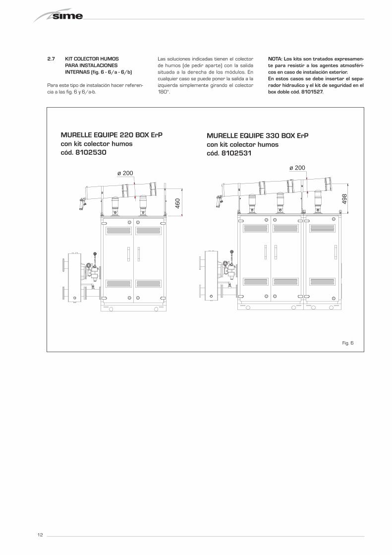
2.7 KIT COLECTOR HUMOS PARA INSTALACIONES INTERNAS (fig. 6 - 6/a - 6/b)
Para este tipo de instalación hacer referen-cia a las fig. 6 y 6/a-b.
Las soluciones indicadas tienen el colectorde humos (de pedir aparte) con la salidasituada a la derecha de los módulos. Encualquier caso se puede poner la salida a laizquierda simplemente girando el colector180°.
NOTA: Los kits son tratados expresamen-te para resistir a los agentes atmosféri-cos en caso de instalación exterior.En estos casos se debe insertar el sepa-rador hidraulico y el kit de seguridad en elbox doble cód. 8101527.
460
ø 200
498
ø 200
MURELLE EQUIPE 220 BOX ErPcon kit collettore fumicod. 8102530
MURELLE EQUIPE 330 BOX ErPcon kit collettore fumicod. 8102531
Fig. 6
MURELLE EQUIPE 220 BOX ErPcon kit colector humoscód. 8102530
MURELLE EQUIPE 330 BOX ErPcon kit colector humoscód. 8102531

13
ES
ENG
527
ø 200
MURELLE EQUIPE 440 BOX ErPcon kit collettore fumicod. 8102532
MURELLE EQUIPE 440 BOX ErP(con box contenitore per separatore idraulicoe kit sicurezze INAIL cod. 8101527)
1100
1600
180
Fig. 6/a
MURELLE EQUIPE 440 BOX ErPcon kit colector humoscód. 8102532
MURELLE EQUIPE 440 BOX ErP(con box doble para separador hidráulico cód. 8101527)

14
180ø 200
565
1100
1600
MURELLE EQUIPE 550 BOX ErP(con box contenitore per separatore idraulicoe kit sicurezze INAIL cod. 8101527)
MURELLE EQUIPE 550 BOX ErPcon kit collettore fumicod. 8102533
Fig. 6/b
MURELLE EQUIPE 550 BOX ErPcon kit colector humoscód. 8102533
MURELLE EQUIPE 550 BOX ErP(con box doble para separador hidráulico cód. 8101527)

2.8 KIT TUBOS DE CONEXIÓN DEL SEPARADOR HIDRÁULICO(fig. 7 - fig. 7/a)
El kit tubos de conexión del separadorhidráulico cód. 8101532 a pedir a partepara los modelos “MURELLE EQUIPE 220-330 BOX ErP” tiene la siguiente composi-ción (fig. 7):– Tronco con brida de impulsión instala-
ción cód. 6291968– Tronco con brida de retorno instalación
cód. 6291968– Juntas, tuercas y tornillos de fijación
M16– Tanque de expansión de 8 litros cód.
6245108 (Presión precarga 1,5 bar -Presión máxima 10 bar) y tubo deconexión cód. 6227661.
ATENCIÓN: En los modelos “220-330BOX ErP” is posible introducir el kit tubosde conexión en un contenedor de protec-ción cód. 8101527 a solicitar a parte.
El kit tubos de conexión del separadorhidráulico cód. 8101533 a pedir a partepara los modelos “MURELLE EQUIPE 440-550 BOX ErP” tiene la siguiente composi-ción (fig. 7/a):– Tronco con brida de impulsión instala-
ción cód. 6291969– Tronco con brida de retorno instalación
cód. 6291971– Juntas, tuercas y tornillos de fijación
M16– Tanque de expansión de 8 litros cód.
6245108 (Presión precarga 1,5 bar -Presión máxima 10 bar) y tubo deconexión cód. 6227661.
ATENCIÓN: En los modelos “440-550BOX ErP” is posible introducir el kit tubosde conexión en un contenedor de protec-ción cód. 8101527 a solicitar a parte.
Fig. 7
Fig. 7/a
15
ES
ENG

16
2.9 PLACA RS-485 (fig. 8)
Cada módulo incluye la placa RS-485 quepermite gestionar las calderas en secuen-cia/cascada.La placa se ubica en el lado posterior delpanel de mando.
2.9.1 Modalidad MODBUS (fig. 8/a)
Esta modalidad permite la comunicación enMODBUS de al menos dos calderas en casca-
da y se efectúa solicitando una segunda fichaRS-485 suministrada en el kit cód. 8092244.
ATENCIÓN: La comunicación será efectuadasolo con la caldera MASTER, (caldera conPAR 15 = 0), interpretando la cascadacomo un único generador de calor de poten-cia:P CASCADA = P CALDERA x N° CALDERAS.
Para el montaje de esta segunda ficha seguirlos siguientes pasos:- Quitar la tapa y conectar eléctricamente la
segunda ficha RS-485 suministrada con
tapa a la ficha RS-485 ya montada en elpanel de la caldera MASTER (caldera conPAR 15 = 0) con el conector cableadosuministrado en el kit.ATENCIÓN: Prestar la máxima atencióncuando se introduzca el conector cablea-do.
- Configurar el DIP SWITCH de la nueva fichaen modalidad MODBUS.
- Cerrar con la tapa de la segunda ficha.- Elegir la configuración de comunicación
adecuada a la red MODBUS presente (PAR17 INST) según cunato descrito en la TablaPAR 17 INST.
x 2
Fig. 8

17
ES
ENG
Fig. 8/a
CONFIGURACIÓN DE LOS PARÁMETROS DEL INSTALADOR:
PAR 16 DIRECCIÓN MODBUS
-- = No habilitado
1...31 = Slave de 1 a 31
(ATENCIÓN: Evitar denominar la caldera con el mismo número ya asignado a otros aparatos)
PAR 17 CONFIGURACIÓN MODBUS-- = No habilitado1...30 = Valor de fábrica: 25(Véase Tabla PAR 17 INST)
ATENCIÓN: Después de haber configurado los parámetros se recomienda apagar y volver a encender la caldera.
1 1200 8 No 1 2 1200 8 No 2 3 1200 8 Pari / 1 4 1200 8 2 5 1200 8 Dispari / 1 6 1200 8 2 7 2400 8 No 1 8 2400 8 No 2 9 2400 8 1
10 2400 8 2 11 2400 8 1 12 2400 8 2 13 4800 8 No 1 14 4800 8 No 2 15 4800 8 1 16 4800 8 2 17 4800 8 1 18 4800 8 2 19 9600 8 No 1 20 9600 8 No 2 21 9600 8 1 22 9600 8 2 23 9600 8 1 24 9600 8 2 25 19200 8 No 1 26 19200 8 No 2 27 19200 8 1 28 19200 8 2 29 19200 8 1 30 19200 8 2
PAR 17 INST Baud Rate N° Bit Dati Parità Bit di StopPar 17 INST Baud Rate No. Data Bit Parity Stop Bit
Pari /
Pari /Pari /
Pari / Pari /
Pari /Pari /
Pari /Pari /
Dispari /
Dispari /Dispari /
Dispari /Dispari /
Dispari /Dispari /
Dispari /Dispari /
EvenEven
EvenEven
EvenEven
EvenEven
EvenEven
OddOdd
OddOdd
OddOdd
OddOdd
OddOdd
TABELLA PAR 17 INST/ Tab. PAR 17 INST
CN10
COMUNICAZIONEMODBUSMODBUS
COMMUNICATION
CONNETTORE CABLATO (cod. 6319173)
WIRED CONNECTOR (cod 6319173)
123456
12
3 DIP SWITCHGESTIONE IN MODBUS
MODBUS MANAGEMENT1 2 3
ON

18
Mod
bus
addr
ess
Variable description
Type
Rea
d / W
rite
U.M
.
Min
valu
e
Max
va
lue
Function
Digital variables (COILS)1 Boiler CH Enable/Request D R/W - 0 1 Richiesta riscaldamento zona 12 Boiler DHW Enable D R/W - 0 1 Abilitazione preparazione ACS3 Boiler Water Filling Function D R/W - 0 1 Non usato
32 Boiler CH Mode D R - 0 1 Stato riscaldamento zona 133 Boiler DHW Mode D R - 0 1 Stato preparazione ACS34 Boiler Flame Status D R - 0 1 Stato presenza fiamma35 Boiler Alarm Status D R - 0 1 Stato presenza allarme
Analog/integer variables(REGISTERS Word 16 bit)
1 Boiler CH Primary Setpoint A R/W 0,1°C 20,0 80,0Setpoint riscaldamento zona 1.
Se viene ricevuto un valore fuori rangeequivale a nessun valore ricevuto e vienemantenuta la termoregolazione di caldaia
a punto fisso o a curva climatica.
2 Boiler DHW Primary Setpoint A R/W 0,1°C 20,0 80,0Setpoint circuito primario durante
la preparazione ACS(al posto di PAR 66 caldaia).
Se viene ricevuto un valore fuori range equivalea nessun valore ricevuto e viene utilizzato
il valore di regolazione presente in caldaia.
3 Boiler DHW Setpoint A R/W 0,1°C 10,0 80,0
Setpoint acqua calda sanitaria.Se viene ricevuto un valore fuori range
equivale a nessun valore ricevutoe viene utilizzato il valore
di regolazione presente in caldaia.
4 Outside Temperature MB A R/W 0,1°C -55,0 95,0
Valore di temperatura esterna comunicato via ModBus.Se viene ricevuto un valore fuori range equivale
a nessun valore ricevuto. Nel caso di conflittola caldaia dà la priorità al valore della sonda
ad essa collegata.
5 Boiler CH Curve Slope A R/W 0,1 3,0 40,0Pendenza della curva climatica della zona 1
(utilizzato al posto della curva impostata in caldaia).Se viene ricevuto un valore fuori range equivale
a nessun valore ricevuto e viene utilizzatala curva climatica presente in caldaia.
6 Boiler CH Curve Displacement A R/W 0,1 -5,0 5,0Valore di shift del set ambiente della zona 1
(utilizzato al posto dello shift impostato in caldaia).Se viene ricevuto un valore fuori range equivale
a nessun valore ricevuto e viene utilizzatolo shift presente in caldaia.
64 Boiler DHW Water Temperature A R 0,1°C 0,0 100,0 Temperatura Sonda Acqua calda sanitaria65 Boiler Primary Water Temperature A R 0,1°C 0,0 100,0 Temperatura Sonda Circuito Primario (Mandata)66 Boiler Return Water Temperature A R 0,1°C 0,0 100,0 Temp. Sonda Ritorno Circuito Primario (NO cascata)67 Boiler Flue Gas Temperature A R 0,1°C 0,0 200,0 Temperatura Sonda Fumi (NO cascata)
68 Boiler Relative Modulation Level A R 0,1% 0,0 100,0 Livello Modulazione (0%=Minima Potenza - 100%=Massima Potenza)
69 Boiler Primary Water Pressure A R 0,1 bar 0,0 6,0 Valore Pressione Acqua Circuito Primario
70 Boiler Outside Temperature A R 0,1°C -100,0 100,0 Valore di temperatura esterna lettodalla caldaia tramite la sonda ad essa collegata.
129 Boiler Current Minute I R/W - 0 59 Non usato130 Boiler Current Hour I R/W - 0 23 Non usato131 Boiler Current Day of the Week I R/W - 1 = Lun 7 = Dom Non usato132 Boiler Current Day of the Month I R/W - 1 31 Non usato133 Boiler Current Month I R/W - 1 12 Non usato134 Boiler Current Year I R/W - 2000 2200 Non usato
192 Boiler Alarm Code I R - 0 100Codice numerico visualizzato durante
anomalia caldaia (Master se in cascata).
193 Boiler Slave 1 Alarm Code I R - 0 100
194 Boiler Slave 2 Alarm Code I R - 0 100Codice numerico visualizzato durante
anomalia caldaia slave 2 (Solo cascata)
195 Boiler Slave 3 Alarm Code I R - 0 100
196 Boiler Slave 4 Alarm Code I R - 0 100
Boiler Slave 5 Alarm Code I R - 0 100
199 Boiler Slave 7 Alarm Code I R - 0 100 Codice numerico visualizzato duranteanomalia caldaia slave 7 (Solo cascata)
200 Boiler Combustion Parameter (Par1) I R - 0 199 Valore del PAR 1 in caldaia (Master se in cascata)201 Boiler Hydraulic Parameter (Par2) I R - 0 199 Valore del PAR 2 in caldaia (Master se in cascata)
Codice numerico visualizzato duranteanomalia caldaia slave 4 (Solo cascata)
Codice numerico visualizzato duranteanomalia caldaia slave 5 (Solo cascata)
Codice numerico visualizzato duranteanomalia caldaia slave 6 (Solo cascata)
Request CH zone 1Enable DHW preparationNot used
State CH zone 1
Descrizione /
State preparation DHWState presence flameState presence alarm
Setpoint CH zone 1.If you receive a value out of range
so the value isn’t received and the boiler temperature control is
maintained of fixed point or a temperature curve.
Setpoint CH during ACS preparation(for PAR 66 installer parameters)
If you receive a value out of range the value isn’t received and it is used
the boiler value regulation .
Setpoint ACS.If you receive a value out of range
the value isn’t received and it is used the boiler value regulation.
External value of temperature by MobBus.If you receive a value out of range
the value isn’t received. In case of conflict the boiler will give priority to the value
of the probe connected to it.
Slope of heating curve of zone 1(it is used instead of the curve set in the boiler).If you receive a value out of range
the value isn’t received and it is used the boiler heating curve.
If you receive a value out of range the value isn’t received and it is used
the boiler heating curve.
Shift value of room zone 1 set(it is used instead of the shift set in the boiler).
DHW temperature sensorCH temperature sensor (Delivery)CH temperature sensor (Return) (No cascade)Smoke temperature sensor (No cascade)Modulation level: (0%= minimum power
100%= maximum power) Pressure value water CHOutside temperature read from the boiler
through the probe connected to it
Not usedNot usedNot usedNot usedNot usedNot used
Numeric code shown during boiler error (If Master is in cascade)
Numeric code shown during slave 02 error(Only cascade)
Numeric code shown during slave 07 error(Only cascade)PAR 1 value (If Master is in cascade)PAR 2 value (If Master is in cascade)
TABELLA DELLE VARIABILI MODBUS / MODBUS BOILER VARIABLES LIST
Codice numerico visualizzato duranteanomalia caldaia slave 3 (Solo cascata)
Numeric code shown during slave 03 error(Only cascade)
Numeric code shown during slave 04 error(Only cascade)Numeric code shown during slave 05 error
(Only cascade)
Numeric code shown during slave 06 error(Only cascade)
7 Boiler Delta-T CH A R/W 0,1 10,0 40,0 Valore di setpoint Delta-T (Mandata - Ritorno) Value setpoint Delta-T (Delivery - Return)
Numeric code shown during slave 01 error(Only cascade)
Codice numerico visualizzato duranteanomalia caldaia slave 1 (Solo cascata)
Code01 READ COIL STATUS
03WRITE MULTIPLE COILS
05 (partially supported) WRITE SINGLE COIL04 (partially supported) READ INPUT REGISTER06 (partially supported) WRITE SINGLE REGISTER
NameCOMANDI MODBUS SUPPORTATI / MODBUS COMMANDS SUPPORTED
15
16READ HOLDING REGISTERSWRITE MULTIPLE REGISTERS
197
198 Boiler Slave 6 Alarm Code I R - 0 100

2.10 PRESIÓN ESTÁTICA DISPONIBLEEN LA INSTALACIÓN
La presión estática residual en las conexio-nes de envío y retorno del generador apa-rece representada en función del caudal enel gráfico de la fig. 9.
2.10.1 Pérdidas de carga del separador
Las pérdidas de carga del separadorhidráulico se indican en el diagrama de lafig. 9.ATENCIÓN: Es posible introducir el sepa-rador hidráulico en un contenedor de pro-tección cód. 8101527 a solicitar a parte.
2.10.2 Separador para los módulos“220-330 BOX ErP”
El separador hidráulico viene suministradoa parte en un kit cód. 8101552 completode juntas, tuercas y tornillos de fijación (fig.10).
2.10.3 Separador para los módulos“440-550 BOX ErP”
El separador hidráulico viene suministradoa parte en un kit cód. 8101553 completode juntas, tuercas y tornillos de fijación (fig.10/a). Se suministran de serie tres “C” desostén que sirven para apoyar el compen-sador en el suelo.
19
ES
ENG
Fig. 10
400
500
600
700
PORTATA (m3/h)
5 10 150
100
200
300
∆p (m
bar)
Mur
elle
Equ
ipe800
20
110 B
OX
ErP
22
0 - 2
20
BO
X ErP
330 - 330 BOX ErP440 - 440 BOX ErP
550 - 550 BOX ErP
660 - 660 BOX ErP
Fig. 9C Fig. 10/a
PRESIÓN ESTÁTICA DISPONIBLE EN LA INSTALACIÓN
PÉRDIDAS DE CARGA DEL SEPARADOR HIDRAULICO
100
150
5
PORTATA (m3/h)
10 15 20 25 300
50
∆p (m
bar)
35 40 45
200
CAUDAL (m3/h)
CAUDAL (m3/h)

2.11 CONEXIÓN ELÉCTRICA
Cada módulo tiene cable eléctrico de ali-mentación que, si debe ser reemplazado,debe ser solicitado a la SIME.La alimentación debe efectuarse con ten-
sión monofásica 230V - 50Hz pasando porun interruptor general protegido por fusi-bles con distancia entre los contactos depor lo menos 3 mm. Respetar las polaridades L - N t la conexiónde tierra.
NOTA: La SIME rehúsa cualquier responsabili-dad ante daños a personas o cosas cau-sados por la falta de conexión a tierra dela caldera.
20
TA2 (24 VRAC)
TA1 (24 VRAC)
SB/SA(5 VDC)
SE (5 VDC)
TS (24 VDC)
SM (5 VDC)
SF (5 VDC)
SR (5 VDC)
RS-485 (24 VAC)
OP (24 VAC)
TPA
V
EV 1-2TFU
CR
0...10 VDC
TRA
EA
ER
PI
2.11.1 Esquema eléctrico generador individual (fig. 11)
LEYENDAF1-2 Fusible (4 AT)TRA Transformador de encendidoPI Bomba instalación alta eficienciaV VentiladorEA Electrodo encendidoER Electrodo detecciónEV1-2 Bobina válvula gasTS Termostato seguridadSF Sonda humosTFU TermofusibleSM Sonda ida calefacciónSR Sonda retorno calefacciónTPA Transductor presión agua
JP1 Seleccione TA2 o 0-10 VDCTA1 Termostato ambiente Zona 1TA2 Termostato ambiente Zona 2SB/SA Sonda anti-gelo sifaoCR Control remoto SIME HOME (opcional)SE Sonda temperatura externa (opcional)OP Reloj programador (opcional)AR Alarma remotaVZ Válvula de zonaAUX Conexión auxiliarRS-485 Ficha CASCADA/MODBUS
NOTA: Conectar el TA1 a los bornes 7-8 despuésde sacar el puente.
CÓDIGOS REPUESTOS CONECTORES:
CN1 cód. 6319162CN2 cód. 6319168CN3 cód. 6319164CN4 cód. 6316203CN6 cód. 6316202CN7 cód. 6316204CN10 cód. 6319165CN12 cód. 6319166CN13 cód. 6319167CN14 cód. 6319169
Fig. 11
Para el rango de 0 ... 10VCC:- Retirar el jumper JP1- Conectar la señal positiva en la terminal 10 de CN6- Conectar la señal negativa en la terminal 4 de CN4.

21
ES
ENG
Pm
axS u
rezze
SE
L
RS
-485
RS
-485
RS
-485
RS
-485
RS
-485
SE
SM
C
(MA
ST
ER
)(S
LA
VE
2)
(SL
AV
E 3
)(S
LA
VE
4)
(SL
AV
E 1
)
RS
-485(S
LA
VE
5)
Fig. 11/a
2.11.2 Conexión eléctrica de los módulos en secuencia/cascada (fig. 11/a)
LEYENDAL LíneaN Neutral√SE Sonda temperatura externaSMC Sonda ida de cascadaRS-485 Ficha gestión en cascada
NOTA: La sonda de temperatura exterior (SE) se debe conectar a la calderaMASTER y la sonda de impulsión de cascada (SMC) a la caldera SLAVE 1.
Las sondas SE, SMC y el cable de conexión de las placas RS-485 se incluyen conlos móduos en el kit de sondas cód. 8092250.
La placa RS-485 para la gestión en secuencia/cascada está colo-cada en la parte posterior del panel de mandos de cada uno delos móduo como se indica en la figura.
CONFIGURACIÓN DE LOS PARÁMETROS DE LA CASCADAEn las instalaciones en secuencia/cascada es necesario configu-rar el siguiente parámetro INST en todas las calderas conecta-das:PAR 15 = 0 para la primera caldera (MASTER)
1 .... 7 para las siguientes calderas (SLAVE)(Evitar denominar las calderas SLAVE con el mismonúmero)
Si en las instalaciones en secuencia/cascada se emplea el colec-tor de humos de polipropileno con válvula de retención, tambiénconfigure el siguiente parámetro INST:PAR 1 = 8 (si la caldera es de gas METANO)
16 (si la caldera es de gas PROPANO)
Para acceder a los parámetros INST véase el punto 3.3.
Además, cuando el número de calderas conectadas en cascadasea superior a dos, hay que configurar también el parámetroOEM A1 de la caldera MASTER. Para acceder a los parámetrosOEM presione a la misma vez las teclas ( y ) durante 2segundos. Una vez se llega al nivel INST, presione nuevamente y al mismotiempo las teclas ( y ) durante otros 2 segundos. En estemomento introduzca el código de acceso constituido por lasiguiente sucesión de TECLAS INSTALADOR: “ + / - / < / > / < “. Entonces configure el parámetro:PAR A1 = Número de generadores de la cascada (3 ... 8)
x 2

22
3 CARACTERISTICAS
5
3
1
2
4
1 - DESCRIPCIÓN DE LOS ICONOS DEL DISPLAY
ICONO MODALIDAD VERANO
ICONO MODALIDAD INVIERNO
ICONO MODALIDAD SANITARIO
ICONO MODALIDAD CALEFACCIÓN
ESCALA GRADUADA DE POTENCIALos segmentos de la barra se iluminan en proporción ala potencia suministrada por la caldera
2 - DESCRIPCIÓN DE LOS MANDOS
TECLA DE FUNCIÓN ON/OFFON = Caldera alimentada eléctricamenteOFF = Caldera alimentada eléctricamente pero nodisponible para el funcionamiento. Están activaslas funciones de protección.
TECLA MODALIDAD VERANOSi se pulsa esta tecla, la caldera funciona sólocuando hay una solicitud de agua sanitaria (fun-ción no disponible)
TECLA MODALIDAD INVIERNOSi se pulsa esta tecla, la caldera funciona en cale-facción y sanitario.
TECLA SET SANITARIOAl pulsar esta tecla, se visualiza el valor de la tem-peratura del agua sanitaria (función no disponi-ble)
TECLA SET CALEFACCIÓNAl pulsar esta tecla por primera vez, se visualiza elvalor de la temperatura del circuito de calefacción 1.Al pulsarla por segunda vez, se visualiza el valor dela temperatura del circuito de calefacción 2.Al pulsarla por terceira vez, se visualiza el valor dela temperatura del circuito de calefacción 3 (Treszonas).
TECLA RESETPermite restablecer el funcionamiento después deuna anomalía de funcionamiento.
TECLA INCREMENTO Y DISMINUCIÓNAl pulsar esta tecla, aumenta o disminuye el valorprogramado.
ICONO FUNCIONAMIENTO QUEMADOR Y BLOQUEO
ICONO NECESIDAD DE RESET
ICONO FUNCIÓN LIMPIACHIMENEAS
DÍGITOS SECUNDARIOSLa caldera muestra el valor de presión de lainstalación (valor correcto entre 1 y 1,5 bar)
3 - TECLAS RESERVADAS AL INSTALADOR(acceso parámetros INST y parámetros OEM)
4 - BARRA LUMINOSACeleste = FuncionamientoRoja = Anomalía de funcionamiento
5 - RELOJ PROGRAMADOR (opcional)Reloj mecánico (cód. 8092228) o digital (cód. 8092229)para programación de calefacción/sanitario.
DÍGITOS PRINCIPALESLa caldera muestra los valores programados, elestado de anomalía y la temperatura externa
Fig. 12
CONEXIÓN PARA PCDebe ser utilizada exclusivamente con el kit de progra-mación de SIME y sólo por personal autorizado. Noconectar otros dispositivos electrónicos (cámaras foto-gráficas, teléfonos, mp3, etc.). Utilizar una herramientapara sacar el tapón y volver a colocarlo después del uso.ATENCIÓN: Puerto de comunicación sensible a las descargas electrostáticas.Antes del uso, se recomienda tocar una superficiemetálica conectada a tierra para descargar la electrici-dad estática.
TECLA INFORMACIÓNSi se pulsa esta tecla repetidamente se van visualizan-do los distintos parámetros.
TECLA FUNCIÓN LIMPIACHIMENEASSi se pulsa esta tecla repetidamente se van visualizan-do los distintos parámetros.
TECLA DISMINUCIÓNSe modifican los valores predeterminados.
TECLA INCREMENTOSe modifican los valores predeterminados.
ICONO PRESENCIA DE FUENTES DE INTEGRACIÓN
3.1 PANEL DE MANDOS (fig. 12)

3.2 ACCESO A LA INFORMACIÓN PARA EL INSTALADOR
Para acceder a la información para el instalador, pulsar la tecla (3 fig. 12). Cada vez que se pulsa la tecla se pasa a la información siguien-
te. Si la tecla no se pulsa, el sistema sale automáticamente de la función. Si no está conectada ninguna ficha de expansión (ZONA MIX o
INSOL) no se mostrarán las relativas informaciones. Lista de información:
1. Visualizzazione temperatura esterna solo con sonda esterna collegata
2. Visualizzazione temperatura sonda mandata riscaldamento (SM)
3. Visualizzazione temperatura sonda sanitario (SS) solo per caldaie istantanee
4. Visualizzazione temperatura sonda ausiliaria o sonda bollitore (SB)
6. Visualizzazione temperatura riscaldamento riferita al primo circuito
7. Visualizzazione temperatura riscaldamento riferita al secondo circuito
9. Visualizzazione numero giri ventilatore in rpm x 100 (es. 4.800 e 1.850 rpm)
10. Visualizzazione ore di funzionamento del bruciatore in h x 100 (es. 14.000 e 10)
11. Visualizzazione numero di accensioni del bruciatore x 1.000 (es. 97.000 e 500)
5. Visualizzazione temperatura sonda fumi (SF)
8. Visualizzazione corrente di ionizzazione in µA
17. Visualizzazione portata sanitaria flussimetro (es. 18 l/min e 0,3 l/min) o stato flussostato (rispettivamente ON e OFF)
12. Visualizzazione numero totale delle anomalie
13. Contatore accessi parametri installatore (es. 140 accessi)
14. Contatore accessi parametri OEM (es. 48 accessi)
15. Contatore accessi parametri CASCATA OEM (es. 05 accessi)
1. Visualización temperatura externa sólo consonda externa conectada
2. Visualización temperatura sonda ida calefac-ción (SM)
3. Visualización temperatura sonda sanitario(SS) solo para calderas instantáneas
4. Visualización temperatura sonda auxiliar osonda calentador (SB)
6. Visualización temperatura calefacción referi-da al primer circuito
7. Visualización temperatura calefacción referi-da al segundo circuito
8. Visualización corriente de ionización en µA
10. Visualización horas de funcionamiento del quemador en h x 100 (ej. 14.000 y 10)
11. Visualización número de encendidos del quemador x 1.000 (ej. 97.000 y 500)
12. Visualización número total deanomalías
5. Visualización temperatura sonda humos (SF) 13. Contador de accesos paráme-tros instalador (ej. 140 accesos)
14. Contador de accesos paráme-tros OEM (ej. 48 accesos)
9. Visualización número de revoluciones del ventilador en rpm x 100 (ej. 4.800 y 1850 rpm)
17. Visualización caudal sanitario caudalímetro (18 l/min y 0,31 l/min) o estado medidor de flujo(respectivamente ON y OFF)
15. Contador de accesos parámetros CASCADA OEM (ej.05 accesos)
23
ES
ENG

24
20. Visualizzazione valore sonda mandata impianto miscelato con schedino ZONA MIX 1 (ingresso S2)
21. Visualizzazione termostato sicurezza ZONA MIX (ingresso S1) rispettivamente ON e OFF
22. Visualizzazione pompa con schedino ZONA MIX 1 (rispettivamente ON e OFF)
23. Visualizzazione comando apertura valvola con schedino ZONA MIX 1 (rispettivamente ON e OFF)
24. Visualizzazione comando chiusura valvola con schedino ZONA MIX 1 (rispettivamente ON e OFF)
25. Visualizzazione valore della sonda mandata impianto miscelato con schedino ZONA MIX 2
26. Visualizzazione termostato sicurezza con schedino ZONA MIX 2 (ingresso S1) rispettivamente ON e OFF
27. Visualizzazione pompa con schedino ZONA MIX 2 (rispettivamente ON e OFF)
28. Visualizzazione comando apertura valvola con schedino ZONA MIX 2 (rispettivamente ON e OFF)
29. Visualizzazione comando chiusura valvola con schedino ZONA MIX 2 (rispettivamente ON e OFF)
30. Visualizzazione valore temperatura sonda solare S1 con schedino solare INSOL
31. Visualizzazione valore temperatura sonda solare S2 con schedino solare INSOL
32. Visualizzazione valore temperatura sonda solare S3 con schedino solare INSOL
33. Visualizzazione relè solare R1 con schedino solare INSOL (rispettivamente ON e OFF)
34. Visualizzazione relè solare R2 con schedino solare INSOL (rispettivamente ON e OFF)
35. Visualizzazione relè solare R3 con schedino solare INSOL (rispettivamente ON e OFF)
18. Visualizzazione valore sonda ritorno riscaldamento (SR)
19. Visualizzazione valore sonda collettore cascata
40. Visualizzazione valore % comando pompa PWM
36. Visualizzazione stato flussostato solare (rispettivamente ON e OFF)
60. Visualizzazione codice errore ultima anomalia
61. Visualizzazione codice errore penultima anomalia
70. Codice di warning
90. Versione software presente su RS-485 (es. versione 01)
91. Versione software presente su schedino EXP (config. ZONA MIX)
92. Versione software presente su 2° schedino EXP (config. ZONA MIX)
45. Visualizzazione temperatura riscaldamento riferita al terzo circuito
20. Visualización valor de solo impulsión instalación mezclada con tarje-ta ZONA MIX 1 (entrada S2)
21. Visualización termostato de seguridad ZONA MIX (entrada S1)respectivamente ON y OFF
22. Visualización bomba tarjeta ZONA MIX 1 (respectivamente ON yOFF)
23. Visualización mando de apertura de la válvula con tarjeta ZONA MIX1 (respectivamente ON y OFF)
24. Visualización mando de cierre de las válvulas con tarjeta ZONA MIX1(respectivamente ON y OFF)
25. Visualización valor de solo impulsión instalación mezclada con tarje-ta ZONA MIX 2
26. Visualización termostato de seguridad con tarjeta ZONA MIX 2(entrada S1) respectivamente ON y OFF
27. Visualización bomba con tarjeta ZONA MIX 2 (respectivamente ONy OFF)
28. Visualización mando de apertura de la válvula con tarjeta ZONA MIX2 (respectivamente ON y OFF)
29. Visualización mando de cierre de las válvulas con tarjeta ZONA MIX 2 (respectivamente ON y OFF)
30. Visualización valor de la temperatura de la sonda solar S1 con tarjeta solar INSOL
31. Visualización valor de la temperatura de la sonda solar S2 con tarjeta solar INSOL
32. Visualización valor de la temperatura de la sonda solar S3 con tarjeta solar INSOL
33. Visualización relé solar R1 con tarjeta solar INSOL (respectivamente ON y OFF)
34. Visualización relé solar R2 con tarjeta solar INSOL (respectivamente ON y OFF)
35. Visualizaciónr relé solar R3 con tarjeta solar INSOL (respectivamente ON y OFF)
19. Visualización valor sonda colector cascada
36. Visualización estado flujostato solar (respectivamente ON y OFF)
40. Visualización valor % mandobomba PWM
18. Visualización valor sonda retorno calefacción (SR)
60. Visualización código error últi-ma anomalía
61. Visualización código errorpenúltima anomalía
70. Código advertencia
90. Versión de software presente enRS-485 (por ejemplo, versión 01)
91. Versión de software presente entarjeta EXP (configuración ZONA MIX)
92. Versión de software presente en 2°tarjeta EXP (configuración ZONA MIX)
45. Visualización temperatura calefacción referidaal tercero circuito

3.3 ACCESO A LOS PARÁMETROS PARA EL INSTALADOR
Para acceder a los parámetros para elinstalador, pulsar simultáneamente lasteclas y durante 2 segundos (3fig. 12).Por ejemplo, el parámetro PAR 23 sevisualiza en el display del panel de mandosdel siguiente modo:
Los parámetros se visualizan con las teclasy , y los valores predeterminado se
modifican con las teclas y . La visualización estándar vuelve automáti-camente después de 60 segundos, o al pul-sar una de las teclas de mando (2 fig. 12)excluido la tecla RESET.
3.3.1 Sustitución de la tarjeta o RESET de los parámetros
Si la tarjeta electrónica se sustituye o sereinicia, para que la caldera vuelva a arran-car es necesario configurar los PAR 1 yPAR 2 asociando a cada tipo de caldera lossiguientes valores:
GAS MODELO PAR 1
220 BOX ErPMETANO 330 BOX ErP 7
(G 20) 440 BOX ErP550 BOX ErP
220 BOX ErPPROPANO 330 BOX ErP 15
(G 31) 440 BOX ErP550 BOX ErP
PARÁMETROS PARA EL INSTALADOR
CONFIGURACIÓN RÁPIDAPAR DESCRIPCIÓN RANGO UNIDAD PASO VALOR
DE MEDIDA PREDET.1 Configuración combustión -- = ND = = “- -”
1 ... 312 Configuración hidráulica -- = ND = = “- -”
1 ... 143 Programador horario 2 1 = DHW + Bomba Ricir. = = 1
2 = DHW3 = Bomba Recirculación
4 Inhabilitación transductor de presión 0 = Inhabilitado = = 11 = Habilitado 0-4 BAR2 = Habilitado 0-6 BAR3 = Habilitado 0-4 BAR (NO ALL 09)4 = Habilitado 0-6 BAR (NO ALL 09)
5 Asignación relé auxiliar AUX 1 = Al. remota = = 12 = B. Recirculación3 = Cargad. automático4 = Alarma remota NC5 = Bomba de calor6 = Válvula de zona 2
6 Barra luminosa presencia tensión 0 = Inhabilitado = = 11 = Habilitado
7 Asignación canales SIME HOME 0 = No asignado = = 11 = Circuito 12 = Circuito de tres zonas
8 N° rev. ventilador Step Encendido 0,0 ... 81 rpmx100 0,1 de 0,1 a 19,9 0,01 de 20 a 81
9 Chimeneas largas 0 ... 20 % 1 010 Configuración dispositivo conectado 1 = SIME HOME = = 1
2 = CR 533 = RVS 43.1434 = RVS 46.5305 = RVS 61.843
11 Corrección valores sonda externa -5 ... +5 °C 1 012 Duración de la retroiluminación -- = Siempre seg. x 10 1 3
0 = Nunca1 ... 199
13 Velocidad bomba modulante -- = Nunca % 10 AuAu = Mod. automática30 ... 100 = % modulación
configurable14 Configuración segunda entrada TA -- = Contacto TA -- -- --
5...160 = Entrada 0...10VDC15 Dirección cascada -- = Inhabilitado -- 1 --
0 = Master1...7 = Slaves
16 Dirección ModBus -- = Inhabilitado -- 1 --1 ...31 = Slaves
17 Configuración comunicación ModBus 1 ... 30 -- 1 2519 Tipo circuito 0 = Dos zonas -- -- 0
1 = Tres zonas
SANITARIO - CALEFACCIÓNPAR DESCRIPCIÓN RANGO UNIDAD PASO VALOR
DE MEDIDA PREDET.20 Temperatura mínima calefacción Zona 1 PAR 64 OEM ... PAR 21 °C 1 2021 Temperatura máxima calefacción Zona 1 PAR 20 ... PAR 65 OEM °C 1 8022 Pendiente curva calefacción Zona 1 3 ... 40 -- 1 2023 Temperatura mínima calefacción Zona 2 PAR 64 OEM ... PAR 24 °C 1 2024 Temperatura máxima calefacción Zona 2 PAR 23 ... PAR 65 OEM °C 1 8025 Pendiente curva calefacción Zona 2 3 ... 40 -- 1 2026 Temperatura mínima calefacción Zona 3 PAR 64 OEM ... PAR 27 °C 1 2027 Temperatura máxima calefacción Zona 3 PAR 26 ... PAR 65 OEM °C 1 8028 Pendiente curva calefacción Zona 3 3 ... 40 -- 1 2029 ∆t calefacción 10 ... 40 °C 1 2030 Tiempo post-circulación calefacción 0 ... 199 Sec. 10 3031 Potencia máxima de calefacción 30 ... 100 % 1 10032 Retraso activación bomba Zona 1 0 ... 199 10 sec. 1 133 Retraso reencendido 0 ... 10 Min. 1 334 Umbral activación fuentes integrativas -- , -10 ... 40 °C 1 “- -”35 Anti-hielo caldera 0 ... +20 °C 1 336 Anti-hielo de la sonda exterior -5 ... +5 °C 1 -237 Franja de saturación -- = Inhabilitado % 1 100
modulación indicador de flujo 0 ... 10038 Tiempo post-circulación sanitario 0 ... 199 Sec. 1 039 Función antilegionela 0 = Inhabilitado -- -- 0
(sólo hervidor) 1 = Habilitado
25
ES
ENG
26
NOTA: Del lado interno de la tapa superiordel panel de la caldera hay aplicada una eti-queta en la que figura el valor que hay queintroducir para los PAR 1 y PAR 2 (fig. 19).
3.3.2 Advertencia
En caso que la caldera funcione pero no demanera óptima y no se activa ninguna alar-ma, pulsar la tecla hasta que se mue-stre la info 70 y el código de advertenciarelativo al tipo de evento en curso. Una vezrestablecido el funcionamiento óptimo, enla info 70 aparece la visualización “- -”. Acontinuación incluimos una tabla de loscódigos que se pueden ver en advertencia:
PARÁMETROS PARA EL INSTALADOR
TARJETA EXPANSIÓN
PAR DESCRIPCIÓN RANGO UNIDAD PASO VALORDE MEDIDA PREDET.
40 Número de tarjetas de expansión 0 ... 3 = 1 0
41 Tiempo carrera válvula mezcla 0 ... 199 10 seg. 1 12
42 Prioridad sanitaria sobre zona mezcla 0 = Paralela = = 1
1 = Absoluta
43 Secado losa 0 = Desactivado = = 0
1 = Curva A
2 = Curva B
3 = Curva A+B
44 Tipo de instalación solar 1 ... 8 = 1 1
45 ∆t bomba colector solar 1 PAR 74 OEM - 1... 50 °C 1 8
46 Retardo integración solar “- -”, 0 ... 199 Min. 1 0
47 Tmin colector solar “- -”, -30 ... 0 °C 1 - 10
48 Tmax colector solar “- -”, 80 ... 199 °C 1 120
RESET PARÁMETROS
PAR DESCRIPCIÓN RANGO UNIDAD PASO VALORDE MEDIDA PREDET.
49 * Reset parámetros predeterminados -- , 1 = = =(PAR 01 - PAR 02 iguales a “- -”)
* En caso de dificultad para comprender la configuración actual o en caso de comportamiento anómalo
o no comprensible de la caldera, se recomienda restablecer los valores iniciales de los parámetros
configurando el PAR 49 = 1 y los PAR 1 y PAR 2 como se describe en el punto 3.3.1.
PARÁMETROS DE CONEXIÓN EN CASCADA
Cuando se instala el aparato en secuencia/cascada (sistemamodular con varios generadores) es necesario configurar entodas las calderas conectadas los siguientes parámetros INST:PAR 15 = 0 para la primera caldera (MASTER)
1 .... 7 para las siguientes calderas (SLAVE)(Evitar denominar las calderas SLAVE con el mismonúmero)
Si en las instalaciones en secuencia/cascada se emplea el colec-tor de humos de polipropileno con válvula de retención, tambiénconfigure el siguiente parámetro INST:PAR 1 = 8 (si la caldera es de gas METANO)
16 (si la caldera es de gas PROPANO)
Además cuando el número de las calderas en cascada es superiora dos, es necesario configurar también el parámetro OEM A1 dela caldera MASTER.Para acceder a los parámetros OEM presione a la misma vez lasteclas ( y ) durante 2 segundos. Una vez dentro del nivelINST vuelva a presionar simultáneamente las tecla ( y )durante otros 2 segundos. En este momento introduzca el códigode acceso constituido por la siguiente sucesión de TECLAS INSTA-LADOR: “ + / - / < / > / < “. Entonces configure el parámetro:PAR A1 = Número de generadores de la cascada (3 ... 8)
CÓDIGO DESCRIPCIÓN
E0 Funcionamiento en reducción
de potencia (∆t entre impulsión
y retorno superior a 40°C)
E1 Sonda exterior con cortocircuito (SE)
E2 Función de precalentamiento activa
E3 TBD
E4 TBD
E5 TBD
E6 TBD
E7 TBD
E8 TBD
E9 TBD
CALDERA PAR 2
Instantánea con valv. desviadora 1e indicador de flujo
Instantánea con valv. desviadora, 2indicador de flujo y combinación solar
Hervidor remoto con valv. desviadora y sonda hervidor 3
vers. T (BAJA INERCIA)
Hervidor a bordo con valv. desviadora y sonda sanitaria 4
(BAJA INERCIA)
Hervidor remoto con valv. desviadora y term. hervidor 5
o solo calefacción vers. T/R(BAJA INERCIA)
Hervidor remoto con doblebomba y sonda hervidor vers. T/R 6
(BAJA INERCIA)
Hervidor remoto con doble bomba y term. hervidor vers. T/R 8
(BAJA INERCIA)
Solo calefacción con sonda anti-hielo 9(BAJA INERCIA)

3.4 SONDA EXTERNA CONECTADA(fig. 13)
En caso de presencia de sonda externa, losajustes de calefacción se obtienen de lascurvas climáticas en función de la tempera-tura externa, y de todos modos se mantie-nen dentro del rango indicado en 3.3 (pará-metros PAR 22 para la zona 1, PAR 25para la zona 2 y PAR 28 para la zona 3). Lacurva climática se puede seleccionar entrelos valores de 3 y 40 (con pasos de 1).Aumentando la pendiente representada porla curva de la fig. 13, se incrementa la tem-peratura de impulsión de la instalaciónconforme a la temperatura externa.
3.5 FUNCIONES DE LA TARJETA
La tarjeta electrónica cumple las siguientesfunciones:– Protección anticongelante circuito cale-
facción y sanitario (ICE).– Sistema de encendido y detección de
llama.– Programación en el panel de mandos de
la potencia y el gas para el funcionamien-to de la caldera.
– Antibloqueo de la bomba para que se ali-mente durante unos segundos despuésde 24 horas de inactividad.
– Protección antilegionella para calderacon calentador acumulador.
– Limpiachimeneas activable desde elpanel de mandos.
– Ajuste de la temperatura con la sondaexterna conectada. Se ajusta desde elpanel de mandos y se activa tanto en elcircuito 1 como en el circuito 2 y 3 de lacalefacción.
– Gestión de 3 circuitos de calefacciónindependientes.
– Regulación automática de la potencia deencendido y máxima de calefacción. Lasregulaciones son gestionadas automáti-camente por la tarjeta electrónica paragarantizar la máxima flexibilidad de usoen la instalación.
– Interfaz con los siguientes sistemas elec-trónicos: control remoto SIME HOMEcód. 8092280/81, termorregulaciónRVS, conexión a una tarjeta de gestión deuna zona de mezcla ZONA MIX cód.8092234, a la tarjeta solar INSOL cód.8092235 y a la tarjeta RS-485 para elcontrol en cascada de hasta 8 calderas oimplementar un tipo de comunicaciónModbus (slave RTU-RS485, ReferenceGuide PI-MBUS-300 Rev. J) cód.8092243. Para la configuración de losdispositivos con la tarjeta de la caldera,programar el parámetro instalador PAR10.
3.6 SONDAS DETECCIÓN DE TEMPERATURA
En la Tabla 4 se indican los valores de resi-stencia (Ω) que se obtienen en las sondas
de calefacción, sanitario y humos al variarla temperatura.
Con la sonda ida de calefacción (SM),retorno de calefacción (SR) y humos (SF)interrumpida, la caldera no funciona enninguno de los dos servicios.
3.7 ENCENDIDO ELECTRONICO
El encendido y la detección de llama se con-trolan por dos electrodos puestos en el que-mador que garantizan la máxima seguridadcon tiempos de intervención por apagadosaccidentales o falta de gas, dentro de unsegundo.
3.7.1 Ciclo de funcionamiento
El encendido del quemador debe tener lugaren un plazo de 10 segundos desde la aper-tura de la válvula de gas. Un fallo de encendido con consiguiente acti-vación de la señal de bloqueo puede atri-buirse a:
– Falta de gasEl electrodo de encendido persiste en ladescarga unos 10 segundos como máxi-mo; si no se verifica el encendido del que-mador, se señaliza la anomalía.
Puede ocurrir al primer encendido odespués de largos períodos de inactivi-dad por presencia de aire en la tuberíadel gas. Puede ser que el grifo del gasesté cerrado o que la válvula tenga unabobina interrumpida y no permita la aper-tura.
– El electrodo de encendido no genera ladescargaEn la caldera se detecta sólo la aperturadel gas para el quemador; transcurridos10 segundos se señaliza la anomalía.
La causa puede ser la interrupción delcable del electrodo o su fijación incorrec-ta en los puntos de conexión. El electrodoestá conectado a masa o muy desgasta-do: es necesario sustituirlo. La tarjetaelectrónica está averiada.
– No hay detección de llamaEn el momento del encendido se detectala descarga continua del electrodo aun-que el quemador resulte encendido.Transcurridos 10 segundos, cesa ladescarga, se apaga el quemador y seseñaliza la anomalía.
La causa puede ser la interrupción delcable del electrodo o su fijación incorrec-ta en los puntos de conexión. El electrodoestá conectado a masa o muy desgasta-do: es necesario sustituirlo. La tarjeta
TABLA 4
Temperatura (°C) Resistencia (Ω)20 12.09030 8.31340 5.82850 4.16160 3.02170 2.22980 1.669
ATENCIÓN: Las curvas se calculan con temperatura ambien-te de 20°C. El usuario puede utilizar los mandos de la calde-ra para variarlas de ±5 °C el set ambiente para el cual estácalculada la curva.
27
ES
ENG

28
electrónica es defectuosa.
Por falta imprevista de corriente el quema-dor se apaga inmediatamente. Al volver lacorriente, la caldera se pone automática-mente en marcha.
3.8 ALTURA DE ELEVACION DISPONIBLE ENLA INSTALACION (fig. 14)
La prevalencia residual para la instalaciónde calefacción está representada, en fun-
ción de la capacidad, del gráfico de la fig. 14.La velocidad de la bomba calefacción modu-lante WILO-STRATOS PARA se ha configu-rado con un valor predeterminado (pará-metro del instalador PAR 13 = Au).
PORTATA (l/h)
0
600
500 30002500200015001000
PR
EVA
LEN
ZA
RES
IDU
A (m
bar)
500
400
100
200
300
700
800
3500 4000
Portat a
(l / h) (mbar)
0
PREVALENZA
400800
1200
782773763748
150020002500300035004000
737708655554448354
WILO-STRATOS PARA
Fig. 14
PR
EVA
LEN
CIA
RES
IDU
AL
(mba
r)
CAUDAL (l/h)
Prevalencia residual(mbar)
Caudal(l/h)

4.1 VALVULA GAS (fig. 16)
La caldera se produce de serie con válvulagas modelo SIT 822 NOVAMIX (fig. 16).
4.2 TRANSFORMACIÓN A OTRO GAS (fig. 17)
Esta operación debe necesariamente serejecutada por personal autorizado y concomponentes originales Sime, so pena depérdida de vigencia de la garantía.Para pasar de gas metano a GLP y vicever-sa, ejecutar las siguientes operaciones:–Cerrar el grifo de gas.–Sustituya el inyectore con OR (1) y la guar-
nición (2) con la suministrada en el kit detransformación.
–Controle todas las conexiones de gasusando agua jabonosa o productos especí-ficos; evite el uso de llamas abiertas.
–Aplicar la etiqueta que indica el nuevogas.
–Calibrar las presiones máxima y mínimade la válvula de gas como se indica en elpunto 4.2.2.
4.2.1 Configuración del nuevo combustible de alimentación
Para acceder a los parámetros para elinstalador, pulsar simultáneamente lasteclas y durante 5 segundos (3fig. 12). Los parámetros se visualizan conlas teclas y . En el display del panel aparecerá el pará-metro PAR 1. Si por ejemplo la caldera encuestión es a metano (G20), aparecerá elSET 8:
Para transformarla a propano (G31) sedeberá programar el SET 16 pulsandorepetidamente la tecla .
La visualización estándar vuelve automáti-camente después de 10 segundos.En la tabla siguiente se indican los ajustes(SET) que se deben programar en todas lasversiones cuando se cambia de gas de ali-mentación.
4.2.2 Calibración de las presiones de la válvula del gas
Verificar los valores de CO2 con un anali-zador de combustión.Secuencia de las operaciones:
1) Pulsar unos segundos la tecla .
2) Pulsar unos segundos la tecla .
3) Buscar los valores de CO2 a la poten-cia máx. indicados a continuación, aju-stando el parcializador (5 fig. 16):
4) Pulsar unos segundos la tecla .
5) Buscar los valores de CO2 a la poten-cia mín. indicados a continuación, aju-stando el tornillo regulador OFF-SET(6 fig. 16):
6) Pulsar varias veces las teclas ypara verificar las presiones; si es
necesario, corregir.
7) Pulsar nuevamente la tecla parasalir de la función.
4.5 MANTENIMIENTO (fig. 20)
Para garantizar la funcionalidad y la eficien-cia del aparato, es necesario someterlo acontroles periódicos conforme a las nor-mas. La frecuencia de los controles depende deltipo de aparato y de las condiciones deinstalación y de uso. En cualquier caso esconveniente hacer ejecutar un controlanual a personal técnico autorizado.
EV1
EV2
1
2
5
6
Fig. 16
LEYENDA1 Toma de presión anterior2 Toma de presión posterior5 Parcializador6 OFF-SET
4 USO Y MANTENIMIENTO
Potencia MÁX.CO2 (Metano) CO2 (Propano)
9,0 ±0,3 10,2 ±0,3
Potencia MÍN.CO2 (Metano) CO2 (Propano)
9,0 ±0,3 10,2 ±0,3
21
Fig. 17
29
ES
ENG
GAS MODELO PAR 1
220 BOX ErPMETANO 330 BOX ErP 8
(G 20) 440 BOX ErP550 BOX ErP
220 BOX ErPPROPANO 330 BOX ErP 16
(G 31) 440 BOX ErP550 BOX ErP

30
Durante las operaciones de mantenimien-to se debe comprobar que el gotero sifónesté lleno de agua(verificación necesariaespecialmente cuando hace mucho tiem-po que no se utiliza el generador).El eventual llenado se efectúa con la bocacorrespondiente (fig. 20).
4.5.1 Función deshollinador (fig. 21)
Para efectuar la verificación de combustiónde la caldera, pulsar unos segundos la teclapara el instalador .La función limpiachimeneas se activa y semantiene 15 minutos. Desde ese momento la caldera empieza afuncionar en calefacción a la máximapotencia, con apagado a 80°C y nuevoencendido a 70°C (ATENCIÓN: Peligro desobretemperatura en caso de instalacio-nes a baja temperatura no protegidas.Antes de activar la función deshollinadorasegurarse que las válvulas del radiadoro eventuales válvulas de zona sean abier-tas). La prueba se puede ejecutar también enfuncionamiento sanitario. Para ello, hay queactivar la función limpiachimeneas y abriruno o varios grifos de agua caliente. Enesta condición, la caldera funciona a lamáxima potencia con el sanitario controla-do entre 60°C y 50°C. Durante toda laprueba, los grifos de agua caliente deberánpermanecer abiertos. Durante los 15 minu-tos de funcionamiento de la función limpia-chimeneas, si se pulsan las teclas y la caldera funciona respectivamente a lamáxima y a la mínima potencia.La función limpiachimeneas se desactivaautomáticamente a los 15 minutos o alpulsar nuevamente la tecla .
4.5.2 Función de secado de la losa (fig. 22)
La función de secado de la losa mantiene el
piso en un perfil de temperatura predefini-do y está habilitada sólo en instalacionescon tarjeta de zona mezclada ZONA MIXcód. 8092234. Los perfiles de temperatura se puedenseleccionar mediante la programación delparámetro instalador PAR 43: 0 = Función desactivada 1 = Configuración curva A 2 = Configuración curva B 3 = Configuración curva A + B
El set de la zona mezclada sigue la evolu-ción de la curva seleccionada y llega a unmáximo de 55°C. Con esta función se ignoran todas las solici-
tudes de calor (calefacción, sanitario, anti-congelante y limpiachimeneas). Durante el funcionamiento, el display mue-stra los días restantes de empleo de la fun-ción (ej.: dígitos principales -15 = faltan 15días para el final de la función). El gráfico dela fig. 22 indica la evolución de las curvas.
ATENCIÓN: - Observar las normas y reglas del fabri-
cante del piso. - El funcionamiento correcto está asegu-
rado sólo si el equipo está instalado cor-rectamente (sistema hidráulico, instala-ción eléctrica, configuración). En casocontrario, el piso podría dañarse.
Fig. 20
Fig. 21
50
45
40
35
30
205 10 15 18 [Tag]0
25
55
A B
1 15 7
X
A + B
1 25
[TVw]
Fig. 22
TVw Set temperatura zona mezclada Tag Período en días x Día de inicio A Curva AB Curva B

4.6 ANOMALÍAS DE FUNCIONAMIENTO
Cuando se presenta una anomalía de fun-cionamiento, en el display se visualiza unaalarma yy llaa bbaarrrraa lluummiinnoossaa cceelleessttee ssee ppoonneeeenn rroojjoo.. A continuación se ofrecen lasdescripciones de las anomalías con susrespectivas alarmas y soluciones:
– ANOMALÍA BAJA PRESIÓN AGUA “ALL02” (fig. 23/1)Si la presión medida por el transductores inferior a 0,5 bar, la caldera se para yen el display se visualiza la anomalía ALL02. Restablezca la presión hasta que lapresión indicada por el transductor estécomprendida entre 1 y 1,5 bares.Si hay que repetir varias veces el pro-cedimiento de carga de la instalación,se recomienda verificar la estanquei-dad efectiva de la instalación de cale-facción (verificar si hay pérdidas).
– ANOMALÍA ALTA PRESIÓN AGUA “ALL03” (fig. 23/2)Si la presión medida por el transductores superior a 4,8 bar, la caldera se paray en el display se visualiza la anomalíaALL 03.
– ANOMALÍA SONDA IDA CALEFACCIÓN“ALL 05” (fig. 23/4)Cuando la sonda ida calefacción (SM)está abierta o en cortocircuito, la calde-ra se para y en el display se visualiza laanomalía ALL 05.
– BLOQUEO LLAMA “ALL 06” (fig. 23/5)Si el control de la llama no detecta lallama al término de una secuencia com-pleta de encendido o si por cualquierotro motivo la tarjeta pierde la visibilidad
de la llama, la caldera se para y en eldisplay aparece la anomalía ALL 06. Pulsar la tecla del panel de man-dos (2) para volver a activar la caldera.
– ANOMALÍA TERMOSTATO SEGURI-DAD/LÍMITE “ALL 07” (fig. 23/6)La apertura de la línea de conexión conel termostato de seguridad/límite deter-mina la parada de la caldera. El control de la llama espera el cierredurante un minuto, manteniendo labomba de la instalación encendida. Si antes de terminar el minuto el termo-stato se cierra, la caldera reanuda elfuncionamiento normal; si no, se para yen el display se visualiza la anomalía ALL07. Pulsar la tecla del panel demandos (2) para volver a activar la cal-dera.
– ANOMALÍA LLAMA PARÁSITA “ALL08” (fig. 23/7)Si la sección de control de la l lamadetecta la llama cuando ésta no debería
estar presente, se ha producido un falloen el circuito de detección de la llama. La caldera se para y en el display apare-ce la anomalía ALL 08.
– ANOMALÍA CIRCULACIÓN AGUA “ALL09” (fig. 23/8)Falta de circulación de agua en el circui-to primario. Si la anomalía se producecon la primera solicitud, la caldera reali-za un máximo de tres tentativos paraasegurar la presencia de agua en el cir-cuito primario y después se detiene; enel display se visualiza la anomalía ALL 09.Si la anomalía se produce durante el fun-cionamiento normal, el display visualizaenseguida la anomalía ALL 09 mante-niendo la bomba de la instalación y labomba hervidor (si está presente)encendidas durante 1 minuto. En estecaso ha tenido lugar un brusco aumentode temperatura dentro de la caldera.Controle si hay circulación de agua den-tro de la caldera y controle el funciona-miento correcto de la bomba. Para salirde la anomalía presione la tecla de los mandos (2). Si la anomalía se vuel-ve a presentar, solicite la intervención depersonal técnico calificado.
– ANOMALÍA SONDA AUXILIAR “AL 10”(fig. 23/9)Cuando la sonda anti-hielo sifón (SA) o
31
ES
ENG
Fig. 23/2
Fig. 23/4
Fig. 23/1
Fig. 23/7
2
Fig. 23/5
2
Fig. 23/6
2
Fig. 23/8
Fig. 23/9

32
sonda calentador L.2000 (SB) estáabierta o en cortocircuito, en el displayse visualiza la anomalía ALL 10.
– INTERVENCIÓN SONDA HUMOS “ALL13” (fig. 23/10)Si interviene la sonda de humos (SF), lacaldera se para y en el display se visuali-za la anomalía ALL 13. Pulsar la tecla
del panel de mandos (2) para vol-ver a activar la caldera.
– ANOMALÍA SONDA HUMOS “ALL 14”(fig. 23/11)Cuando la sonda de humos (SF) estáabierta o en cortocircuito, la caldera separa y en el display se visualiza la ano-malía ALL 14.
– ANOMALÍA DEL VENTILADOR “ALL 15”(fig. 23/12)Las revoluciones del ventilador no corre-sponden al rango de velocidad preesta-blecido. Si la anomalía dura dos minutos,la caldera ejecuta una parada forzada detreinta minutos. Al término de la paradaforzada, la caldera vuelve a intentar elencendido.
– ANOMALÍA SONDA EXTERNA “PARPADEANT” (fig. 23/13)Cuando la sonda externa (SE) está corto-circuitada, el display parpadea el símbolo
. Durante esta anomalía, la calderasigue funcionando normalmente.
– INTERVENCIÓN TERMOSTATO DESEGURIDAD PRIMERA ZONA MEZCLA-DA “ALL 20” (fig. 23/14)Cuando la tarjeta ZONA MIX resultaconectada a la caldera, la intervencióndel termostato de seguridad apaga labomba de la instalación de la zona mez-clada, se cierra la válvula mix de zona yen el display aparece la anomalía ALL20. Durante dicha anomalía la calderasigue funcionando normalmente.
– ANOMALÍA AVERÍA SONDA IMPUL-SIÓN PRIMERA ZONA MEZCLADA“ALL 21” (fig. 23/15)Cuando la tarjeta ZONA MIX resultaconectada a la caldera y la sonda deimpulsión está abierta o cortocircuitada,en el display aparece la anomalía ALL 21.Durante dicha anomalía la caldera siguefuncionando normalmente.
– INTERVENCIÓN TERMOSTATO DESEGURIDAD SEGUNDA ZONA MEZ-CLADA “ALL 22” (fig. 23/16)Cuando la tarjeta ZONA MIX resultaconectada a la caldera, la intervencióndel termostato de seguridad apaga labomba de la instalación de la zona mez-clada, se cierra la válvula mix de zona yen el display aparece la anomalía ALL
22. Durante dicha anomalía la calderasigue funcionando normalmente.
– ANOMALÍA AVERÍA SONDA IMPUL-SIÓN SEGUNDA ZONA MEZCLADA“ALL 23“ (fig. 23/17)Cuando la tarjeta ZONA MIX resultaconectada a la caldera y la sonda deimpulsión está abierta o cortocircuitada,en el display aparece la anomalía ALL23. Durante dicha anomalía la calderasigue funcionando normalmente.
– ANOMALÍA SONDA DEL COLECTORSOLAR (S1) “ALL 24” (fig. 23/18)Cuando la sonda solar está abierta o encortocircuito en el display aparece laanomalía ALL 24. Durante dicha ano-malía la caldera sigue funcionando nor-malmente pero pierde la función solarque ya no está disponible.
– ANOMALÍA SONDA ACUMULADORSOLAR (S2) “ALL 25” (fig. 23/19)Cuando la sonda solar está abierta o encortocircuito en el display aparece laanomalía ALL 25. Durante dicha ano-malía la caldera sigue funcionando nor-malmente pero pierde la función solarque ya no está disponible.
– ANOMALÍA SONDA AUXILIAR (S3)“ALL 26” (fig. 23/20)Cuando la sonda solar está abierta o encortocircuito en el display aparece laanomalía ALL 26. Durante dicha ano-malía la caldera sigue funcionando nor-malmente pero pierde la función solar
Fig. 23/11
Fig. 23/12
2
Fig. 23/10
Fig. 23/14
Fig. 23/15
Fig. 23/13
Fig. 23/18
Fig. 23/19
Fig. 23/16
Fig. 23/17

que ya no está disponible.
– ANOMALÍA COHERENCIA APLICACIÓNSOLAR “ALL 27” (fig. 23/21).Cuando la configuración hidráulica no escompatible con l’aplicación solar elegida,en el display aparece la anomalía ALL 27.Durante dicha anomalía la caldera siguefuncionando normalmente pero para laplaca solar por la cual es activa la ano-malía, está disponible solamente la fun-ción anticongelante colector.
– ANOMALÍA COHERENCIA ENTRADA(S3) SÓLO POR SISTEMA 7 “ALL 28”(fig. 23/22)Cuando una sonda se conecta en vez deun contacto limpio de entrada S3 de laplaca, en el display aparece la anomalíaALL 28. Durante dicha anomalía la calde-ra sigue funcionando normalmente peropara la placa solar por la cual es activala anomalía, está disponible solamente lafunción anticongelante colector.
– ANOMALÍA NUMERO DE TARJETACONECTADOS “ALL 29” (fig. 23/23)Cuando una de las fichas ZONA MIX/INSOL reulta falla o no comunica la pan-tal la muestra la anomal ía ALL 29.Durante esta anomalía la caldera con-tinúa el normal funcionamiento con laexcepción de la función ZONAMIX/INSOL.
– ANOMALÍA SONDA RETORNO CALE-FACCIÓN “ALL 30” (fig. 23/24)Cuando la sonda de retorno de calefac-ción (SR) está abierta o en cortocircuitola pantalla muestra la anomalía ALL 30.
Durante esta anomalía la caldera con-tinúa el normal funcionamiento.
– ANOMALÍA SONDA IMPULSIÓNCASCADA “ALL 31” (fig. 23/25)Cuando la sonda de impulsión de casca-da (SMC) está abierta o en cortocircuitola pantalla muestra la anomalía ALL 31.Durante esta anomalía la caldera con-tinúa el normal funcionamiento.
– ANOMALÍA CONFIGURACIÓN INSTA-LACIÓN TRES ZONAS “ALL 32” (fig.23/26)Cuando las fichas conectadas RS-485no tienen un número suficiente y/o almenos una no es una ficha de zona mez-clada, la caldera se para y en la pantallase muestra la anomalía ALL 32. La cal-dera reinicia cuando se activa la correc-ta configuración para instalaciones de 3zonas.
– ANOMALÍA COMUNICACIÓN FICHARS-485 EN MODALIDAD MODBUS“ALL 33” (fig. 23/27)Cuando el PAR 16 es diferente de “- -” yno se produce comunicación entre laficha de caldera y la ficha RS-485 enmodalidad MODBUS durante al menoscuatro minutos la caldera se para y en lapantalla se muestra la anomalía ALL 33.La caldera reinicia cuando se restablecela comunicación o cuando se configura elPAR 16 = “- -”.
– ANOMALÍA COMUNICACIÓN FICHARS-485 EN MODALIDAD CASCADA“ALL 34” (fig. 23/28)
Cuando el PAR 15 es diferente de “- -” yno hay comunicación entre la ficha decaldera y la ficha RS-485 en modalidadCASCADA la caldera se para y en la pan-talla se muestra la anomalía ALL 34. Lacaldera reinicia cuando se restablece lacomunicación o cuando se configura elPAR 15 = “- -”.
– ANOMALÍA COMUNICACIÓN FICHARS-485 Y FICHA RS-485 “ALL 35” (fig.23/29)Cuando el PAR 15 es diferente de “- -” yno hay comunicación entre las dos fichasRS-485 la caldera se para y en la pantal-la se muestra la anomalía ALL 35. Lacaldera reinicia cuando se restablece lacomunicación o cuando se configura elPAR 15 = “- -”.
ATENCIÓN: En caso de conexión ensecuencia/cascada en la pantalla delmando remoto SIME HOME se muestranlos códigos de error 70 y 71:- ALARMA 70
Cuando interviene una anomalía quebloquea el funcionamiento de la casca-da (sonda de impulsión de cascada ALL31) la pantalla del mando remoto SIMEHOME muestra la alarma 70. Compro-bar la anomalía en la cascada.
- ALARMA 71Cuando interviene una anomalía en unode los módulos y los otros continúanfuncionando lo permitido, la pantalladel mando remoto SIME HOME mue-stra la alarma 71. Comprobar la ano-malía en la cascada.
33
ES
ENGFig. 23/20
Fig. 23/21
Fig. 23/22
Fig. 23/24
Fig. 23/25
Fig. 23/27
Fig. 23/28
Fig. 23/29
Fig. 23/26
Fig. 23/23

34
ENCENDIDO MODULO INDIVIDUAL (fig.24)
El primer encendido de la caldera debe serefectuado por personal técnico autorizado.En lo sucesivo, para volver a poner la calde-ra en servicio, seguir detenidamente lassiguientes instrucciones: abrir el grifo delgas para permitir el flujo del combustible yponer el interruptor general de la instala-ción en “encendido”. Al alimentarse, la calde-ra ejecuta una secuencia de verificación y eldisplay visualizará el estado de funciona-miento normal, señalizando siempre la pre-sión de la instalación. La barra luminosaceleste encendida indica la presencia detensión. Pulsar la tecla del panel demandos (pos. 2) para activar el funciona-miento invernal. El display se presentacomo indica la figura.
NOTA: A la primera presión de las teclasde mandos (2) se enciende el display, a lapresión siguiente de la tecla es attivabilela modalidad de funcionamiento seleccio-nada.
REGULACIÓN DE LA TEMPERATURA DELAGUA DE CALEFACCIÓN MODULO INDIVI-DUAL (fig. 25)
Para programar la temperatura del agua decalefacción deseada, pulsar la tecla delpanel de mandos (pos. 2).Al pulsarla por primera vez, se seleccionael SET del circuito de calefacción 1. Al pul-sarla por segunda vez, se selecciona el SETdel circuito de calefacción 2. Al pulsarla portercera vez, se selecciona el SET del circui-to de calefacción 3 (Tres zonas).El display se presenta como indica la figura. Modificar los valores con las teclas y
2
Circuitoriscaldamento 2
Circuitoriscaldamento 3(impianto trezone)
Fig. 25
PARA EL USUARIO
ADVERTENCIAS– Desactivar el equipo en caso de rotura y/o mal funcionamiento, absteniéndose de realizar cualquier intento de repa-
ración o de intervención directa. Para esto dirigirse exclusivamente a personale técnico autorizado.
– La instalación de la caldera y cualquier intervención de asistencia o mantenimiento deben ser ejecutadas por perso-
nal calificado conforme a la norma CEI 64-8. Queda absolutamente prohibido abrir abusivamente los dispositivos sel-
lados de fábrica.
– Está absolutamente prohibido obstruir las rejillas de aspiración y la abertura de aireación del local donde está instala-
do el aparato.
– El fabricante no se hace responsable de eventuales daños derivados de usos inadecuados del aparato.
– Por razones de seguridad se desaconseja el uso de el aparado por parte de niños o personas incapaces no asisti-
dos. Sorvegiare los niños para que no jueguen con el aparado.
ENCENDIDO Y FUNCIONAMIENTO
2
Fig. 24
Circuito de calefacción 2
Circuito de calefacción 3(tres zonas)

. La visualización estándar vuelve alpulsar la tecla o al cabo de 10 segun-dos si no se pulsa ninguna tecla.
REGULACIÓN CON SONDA EXTERNA CONECTADA (fig. 25/a)Cuando hay una sonda externa instalada, elvalor de la temperatura de impulsión es ele-gido automáticamente por el sistema, queadecua la temperatura ambiente rápida-mente en función de las variaciones de latemperatura externa. Si se desea aumentar o reducir el valor detemperatura establecido por la tarjeta elec-trónica, seguir las indicaciones del apartadoanterior. El nivel de distinta corrección de unvalor de temperatura proporcional calcula-do. El display se presenta como indica lafigura 25/a.
APAGADO MODULO INDIVIDUAL (fig. 24)
En caso de breves ausencias, pulsar latecla ( ) del panel de mandos (pos. 2).El display se presenta como indica la fig.24. De este modo, manteniéndose activas laalimentación eléctrica y la alimentación delcombustible, la caldera está protegida porlos sistemas anticongelante y antibloqueode la bomba. En caso de períodos de inactividad prolon-gados, se recomienda desconectar la ten-sión eléctrica apagando el interruptorgeneral de la instalación, cerrar el grifo delgas y, si se prevén bajas temperaturas,vaciar el circuito hidráulico para evitar larotura de las tuberías a causa de la conge-lación del agua.
ANOMALÍAS Y SOLUCIONES
Cuando se presenta una anomalía de fun-cionamiento, en el display se visualiza unaalarma y la barra luminosa celeste sepone en rojo. A continuación se ofrecen lasdescripciones de las anomalías con susrespectivas alarmas y soluciones:
– ALL 02 (fig. 27/a)Si la presión del agua medida es inferiora 0,5 bar, la caldera se para y en eldisplay se visualiza la anomalía ALL 02.Restablezca la presión hasta que la pre-sión indicada por el transductor estécomprendida entre 1 y 1,5 bares.Si hay que repetir varias veces el pro-cedimiento de carga de la instalación,
se recomienda recurrir a personal téc-nico autorizado para hacerle verificarla estanqueidad efectiva de la instala-ción de calefacción (control de eventua-les pérdidas).
– ALL 03Solicitar la intervención de personaltécnico autorizado.
– ALL 05Solicitar la intervención de personaltécnico autorizado.
– ALL 06 (fig. 27/c)Pulsar la tecla del panel de man-dos (2) para volver a activar la caldera.Si la anomalía persiste, solicitar laintervención de personal técnico auto-rizado.
– ALL 07 (fig. 27/d)Pulsar la tecla del panel de man-dos (2) para volver a activar la caldera.
Si la anomalía persiste, solicitar laintervención de personal técnico auto-rizado.
– ALL 08Solicitar la intervención de personaltécnico autorizado.
– ALL 09Solicitar la intervención de personaltécnico autorizado.
– ALL 10Solicitar la intervención de personaltécnico autorizado.
– ALL 13 (fig. 27/e)Pulsar la tecla del panel de man-dos (2) para volver a activar la caldera.Si la anomalía persiste, solicitar la
Fig. 25/a
Fig. 27/a
2
Fig. 27/c
2
Fig. 27/d
35
ES
ENG

36
intervención de personal técnico auto-rizado.
– ALL 14Solicitar la intervención de personaltécnico autorizado.
– ALL 15Solicitar la intervención de personaltécnico autorizado.
– “ PARPADEANT”Solicitar la intervención de personaltécnico autorizado.
– De ALL 20 hasta ALL 29Solicitar la intervención de personaltécnico autorizado.
– De ALL 30 hasta ALL 35Solicitar la intervención de personaltécnico autorizado.
– ALL 70 y ALL 71Estas alarmas se muestran en la pan-talla del mando remoto SIME HOME.Solicitar la intervención de personaltécnico autorizado.
TRANSFORMACION GAS
En el caso que sea necesaria la transfor-mación para un gas diferente al que la cal-dera ha sido fabricada es necesario dirigir-se a personal técnico autorizado.
MANTENIMIENTO
El mantenimiento preventivo y el controldel funcionamiento de los aparatos y delos sistemas de seguridad podrán efec-tuarse por un técnico autorizado.
La caldera se suministra con un cableeléctrico que en caso de sustitucióndeberá ser suministrado por SIME.
ELIMINACIÓN DEL APARATO
El aparato, una vez llegado al final de suvida útil, DEBE SER ELIMINADO DE MANE-RA DIFERENCIADA, como prevé la legisla-ción vigente.
NO DEBE ser eliminado junto con los resi-duos urbanos.
Puede ser entregado a los centros de reco-lección diferenciada, si existen, o bien a losrevendedores que ofrecen este servicio.
La eliminación diferenciada evita potencia-les daños al ambiente y a la salud. Permiteademás recuperar muchos materialesreciclables, con un importante ahorroeconómico y energético.
2
Fig. 27/e

FOR THE INSTALLATION TECHNICIAN
CONTENTS
1 DEVICE DESCRIPTION . . . . . . . . . . . . . . . . . . . . . . . . . . . . . . . . . . . . . . . . . . . . . . . . . . . . . . . . . . . . . . . . . . . . . . . .page 38
2 INSTALLATION . . . . . . . . . . . . . . . . . . . . . . . . . . . . . . . . . . . . . . . . . . . . . . . . . . . . . . . . . . . . . . . . . . . . . . . . . . . . . . . .page 44
3 FEATURES . . . . . . . . . . . . . . . . . . . . . . . . . . . . . . . . . . . . . . . . . . . . . . . . . . . . . . . . . . . . . . . . . . . . . . . . . . . . . . . . . . . .page 56
4 USE AND MAINTENANCE . . . . . . . . . . . . . . . . . . . . . . . . . . . . . . . . . . . . . . . . . . . . . . . . . . . . . . . . . . . . . . . . . . . . .page 63
IMPORTANT
When turning the boiler on for the first time it is best to run the following checks:
– Make sure there are no flammable liquids or materials in the boiler’s near vicinity.
– Make sure that electrical connections are correct and that the grounding wire is connected to a good
grounding system.
– Open the gas tap and check the seal on the fixtures including the burner.
– Make sure that the boiler is set to operate with the type of gas supplied.
– Make sure that the exhaust flue is free and/or correctly assembled.
– Make sure that any shutters are open.
– Make sure that the system was filled with water and that all air was drained.
– Make sure the distributor is not obstructed.
– Discharge any air in the gas pipes by using the pressure escape on the gas valve.
FONDERIE SIME S.p.A. located in Via Garbo 27 - Legnago (VR) - Italy declares that its hot water boilers, CE appro-ved according to Gas Directive 90/396/CEE and equipped with safety thermostat calibrated to maximum 110°C,are exempt from PED Directive 97/23/CEE application field because they meet the requisites foreseen in arti-cle 1 comma 3.6 therein.
MU
REL
LE E
QU
IPE
22
0-3
30
-44
0-5
50
BO
X E
rP -
ENG
LIS
H
CONFORMITY
Our Company declares that MURELLE EQUIPE 220-330-440-550 BOX ErP boilers comply with the essential requi-rements of the following directives:- Boiler Efficiency Directive 92/42/EEC- Gas Appliances Directive 2009/142/EC- Electromagnetic Compatibility Directive 2004/108/EC- Low Voltage Directive 2006/95/EC- Ecodesign Directive 2009/125/EC- Regulation (EU) N. 813/2013 - 811/2013

38
1.1 INTRODUCTION
MURELLE EQUIPE 220-330-440-550
BOX ErP are pre-mixed condensation hea-ting modules intended only for heating,inter-connectible and easy to assemble,
designed to work singularly or in sequen-ce/cascade autonomously.
1 DEVICE DESCRIPTION
1.2 DIMENSIONS MODULES
1.2.1 “MURELLE EQUIPE 220 BOX ErP”
Fig. 1
FIXTURESM System supply (Flange PN6-DN100)R System return (Flange PN6-DN100)G Gas (Flange PN6-DN50)S3 Condensation drain ø 40
90
180
156396
790
567
272
S3
G
M
307
777
R
260380 1100
648
1600
2010
470 390
NOTE: Assembly of a hydraulic separator or plate exchanger is also mandatory. The hydraulic separator is supplied with modu-les in a kit code 8101552 and the tubes connecting the hydraulic separator in the kit code 8101532. Fixtures may be assembledon the left-hand side by moving the system supply/return manifold blind flanges.

39
ES
ENG
1.2.2 “MURELLE EQUIPE 330 BOX ErP”
90
180
156396
790
567
272
S3
G648
1600
2010
390630470
1730380 260
307
777
M
R
1100 630
Fig. 1/a
FIXTURESM System supply (Flange PN6-DN100)R System return (Flange PN6-DN100)G Gas (Flange PN6-DN50)S3 Condensation drain ø 40
NOTE: Assembly of a hydraulic separator or plate exchanger is also mandatory. The hydraulic separator is supplied with modu-les in a kit code 8101552 and the tubes connecting the hydraulic separator in the kit code 8101532. Fixtures may be assembledon the left-hand side by moving the system supply/return manifold blind flanges.

40
1.2.3 “MURELLE EQUIPE 440-550 BOX ErP”
180
790396
156
567
90
272 56
2
1197
S3
M
R
G
1600
2010
2830590500
390630470630470
635
562
MURELLE EQUIPE 440 BOX ErP
180
790396
156
567
90
272 56
2
1197
S3
M
R
G
1600
2010
2200590500
390470630470
635
562
MURELLE EQUIPE 550 BOX ErP
Fig. 1/a
FIXTURESM System supply (Flange PN6-DN100)R System return (Flange PN6-DN100)G Gas (Flange PN6-DN50)S3 Condensation drain ø 40
NOTE: Assembly of a hydraulic separator or plate exchanger is also mandatory. The hydraulic separator is supplied withmodules in a kit code 8101553 and the tubes connecting the hydraulic separator in the kit code 8101533. Fixtures maybe assembled on the left-hand side by moving the system supply/return manifold blind flanges.

41
ES
ENG
FR
1.3 TECHNICAL SPECIFICATIONS
MURELLE EQUIPE 220 BOX ErP 330 BOX ErP 440 BOX ErP 550 BOX ErP
Generators with a heat output kW 105.4 n° 2 3 4 5
Heat output
Nominal (80-60°C) (Pn max) kW 210.8 316.2 421.6 527.0
Nominal (50-30°C) (Pn max) kW 225.2 337.8 454.0 563.0
Minimum (80-60°C) (Pn min) kW 20.8 20.8 20.8 20.8
Minimum (50-30°C) (Pn min) kW 23.2 23.2 23.2 23.2
Heat input (*)
Nominal (Qn max - Qnw max) kW 216 324 432 540
Minimum (Qn min - Qnw min) kW 21.6 21.6 21.6 21.6
Min/max operating yield (80-60°C) % 96.4/97.6 96.4/97.6 96.4/97.6 96.4/97.6
Min/max operating yield (50-30°C) % 107.4/104.2 107.4/104.2 107.4/104.2 107.4/104.2
Operating yield at 30% (40-30°C) % 105.4 105.4 105.4 105.4
Losses after shutdown to 50°C (EN 15502) W 498 747 996 1245
Feeding tension V-Hz 230-50 230-50 230-50 230-50
Absorbed power consumption (Qn max) W 516 774 1032 1290
Absorbed power consumption (Qn min) W 134 138 142 146
Absorbed power consumption C.H. pump W 260 (130 x 2) 390 (130 x 3) 520 (130 x 4) 650 (130 x 5)
Electrical protection grade IPX4D IPX4D IPX4D IPX4D
Energy efficiency
Seasonal energy efficiency class of the heating system A A A A
Seasonal energy efficiency of the heating system % 90 91 91 91
Sound power of the heating system dB (A) --- --- --- ---
Single module temperature regulation °C 20/80 20/80 20/80 20/80
Water content modules l 36.3 55.9 72.6 92.2
Max operating pressure (PMS) bar 5 5 5 5
Max operating temperature (T max) °C 85 85 85 85
Exhaust temperature at max flow rate (80-60°C) °C 64 64 64 64
Exhaust temperature at min flow rate (80-60°C) °C 51 51 51 51
Exhaust temperature at max flow rate (50-30°C) °C 45 45 45 45
Exhaust temperature at min flow rate (50-30°C) °C 40 40 40 40
Smokes flow min/max g/s 10.28/103.34 10.28/155 10.28/206.67 10.28/258.34
CO2 at max/min flow rate (G20) % 9.0/9.0 9.0/9.0 9.0/9.0 9.0/9.0
CO2 at max/min flow rate (G31) % 10.2/10.2 10.2/10.2 10.2/10.2 10.2/10.2
NOx measured mg/kWh 24 24 24 24
Max. output pressure fumes manifold Pa 375 375 375 375
Max. pressure independent fumes Pa 428 428 428 428
PIN number 1312CM5621 1312CM5621 1312CM5621 1312CM5621
Category II2H3P II2H3P II2H3P II2H3P
Category in France I2Er3P I2Er3P I2Er3P I2Er3P
Type B23-B53-B23P-B53P B23-B53-B23P-B53P B23-B53-B23P-B53P B23-B53-B23P-B53P
NOx emission class 5 5 5 5
Wight when empty kg 380 615 760 995
Gas and nozzle pressure
Supply pressure (G20/G25) mbar 20/25 20/25 20/25 20/25
Supply pressure (G31) mbar 37 37 37 37
Number of nozzles n° 2 3 4 5
Nozzle diameter (G20/G25) ø 12.4 12.4 12.4 12.4
Nozzle diameter (G31) ø 8.2 8.2 8.2 8.2
Consumption gas at nominal output (G20) m3/h 22.84 34.26 45.68 57.10
Consumption gas at minimum output (G20) m3/h 2.28 2.28 2.28 2.28
Consumption gas at nominal output (G31) kg/h 16.76 25.14 33.52 41.90
Consumption gas at minimum output (G31) kg/h 1.68 1.68 1.68 1.68
(*) Heat input of the heating system measured using lower heating value (LHV)

42
1.4 OPERATING DIAGRAM (fig. 2)
M
R
1
2
3
19
20
721
25
23
22G
26
29
12
1614
15
18
2427
6
8
109
11
17S3
530
Fig. 2
KEY1 Cascade supply probe (SMC)2 Hydraulic compensator3 ---------- 5 Condensation drain siphon6 Gas valve7 ---------- 8 Fan9 Heating supply probe (SM)
10 Safety thermostat 100°C11 Exhaust probe (SF)12 Primary exchanger14 Heating return probe (SR)15 Water pressure transducer16 Air release vent17 Check valve18 Pump high efficiency
19 ---------- 20 ---------- 21 ---------- 22 3-way drain tap23 System supply tap24 Single module drain25 Gas tap26 8 litre expansion tank27 Safety valve 5 bar29 ---------- 30 Antifreeze siphon sensor (SB/SA)
FIXTURESM System supplyR System returnG GasS3 Condensation drain

43
ES
ENG
1
2
3
4
5
6
7
8
9
10
111213
14
15
1617
1.5 MAIN COMPONENTS (fig. 3)
Fig. 3
Codice/Code 8111271Modello/Model MURELLE EQUIPE 220 BOX ErPMatricola/Serial n. 9999999999
PAR 1 = 8 (G20) / 16 (G31)PAR 2 = 9
KEY1 System return manifold2 Gas tap3 System supply manifold4 Gas valve5 Fan6 Ignition electrode7 Primary exchanger8 Ignition transformer9 Control panel
10 Heating return probe (SR)11 Heating supply probe (SM)12 Safety thermostat 100°C13 Detection electrode14 Pump high efficiency15 System supply tap16 3-way drain tap17 Gas manifold
CAUTION: To access the control panel (9)remove the two screws which secure it tothe support bracket and turn the paneldownwards.
MODEL
SERIAL NUMBER
YEAR OF CONSTRUCTION
WATER CONTENT IN BOILER
HEAT INPUT MAX
HEAT OUTPUT MAX (80-60°C)
HEAT OUTPUT MAX (50-30°C)
MAX OPERATING PRESSURE
CONTENTS D.H.W.
HEAT INPUT MAX D.H.W.
MAX OPERATING PRESSURE D.H.W.
D.H.W. FLOW RATE
POWER SUPPLYMAX POWER ABSORBED
COUNTRIES OF DESTINATION
CATEGORY
TYPE
CODE
DIRECTIVE OF REFERENCE
PIN NUMBER
HEAT INPUT MIN
HEAT OUTPUT MIN (80-60°C)
HEAT OUTPUT MIN (50-30°C)
MAX OPERATING PRESSURE
HEAT INPUT MIN D.H.W.
MAX OPERATING PRESSURE D.H.W.
ELECTRICAL PROTECTION GRADE
NOx CLASSCODE GAS COUNCIL NUMBER (UK)
CERTIFICATION WRAS (UK)
TYPE OF GASGAS SUPPLY PRESSURECLASSIFICATIONS
Fig. 3/a
1.6 TECHNICAL DATA PLATE (fig. 3/a)

44
Installation is permanent and must exclu-sively be performed by specialised andqualif ied personnel, fol lowing all theinstructions and provisions included inthis manual. Current regulations must alsobe met.
2.1 SUPPLY (fig. 4)
MURELLE EQUIPE 110 BOX ErP heatmodules, inter-connectible by flange, aresupplied with an external pre-painted zinc-coated laminate case. They are completewith supply/return water and gasmanifolds, external temperature probe kit,cascade supply and RS-485 code8092250 board connection cable. Availa-ble separately:– Tubes connecting the hydraulic separa-
tor kit code 8101532 for modules “220-330 BOX ErP” and code 8101533 formodules “440-550 BOX ErP”
– Double box (size: 1100 x 790 x 1600) forhydraulic separator code 8101527
– Hydraulic separator kit code 8101552for modules “220-330 BOX ErP” andcode 8101553 for modules “440-550BOX ErP”
– Polypropylene exhaust manifold kit forindoor installation (purposely treated toresist weathering when installed out-doors):code 8102530 for “220 BOX ErP”modulecode 8102531 for “330 BOX ErP”modulecode 8102532 for “440 BOX ErP”modulecode 8102533 for “550 BOX ErP”module
– Exhaust terminal code 8089530 for out-door installations.
To electrically connect the modules and toassemble the exhaust for indoor or outdoor
installations, see points 2.6, 2.7 and 2.10 inthis manual.
2.2 INSTALLATION
2.2.1 Indoors
MURELLE EQUIPE 220-330-440-550BOX ErP heat modules can be installed inboiler rooms whose size and requirementsmeet current regulations.Furthermore, vents, with surface areas atleast 3.000 sq. cm or 5.000 sq. cm forgas with density over 0.8, must be installedin the outer walls for room ventilation.
2.2.2 Outdoors
MURELLE EQUIPE 220-330-440-550BOX ErP heat modules can also be instal-led outdoors with the specific exhaust forsingle module code 8089530.
2 INSTALLATION
160
0
47
03
08
1100790
396
396
63
55
62
BOX CONTENITORE DOPPIO PER COMPENSATOREIDRAULICO E KIT SICUREZZE INAIL cod. 8101527PER “MURELLE EQUIPE 220 - 330 BOX ErP”
1100
160
0
790
BOX CONTENITORE DOPPIO PER COMPENSATOREIDRAULICO E KIT SICUREZZE INAIL cod. 8101527PER “MURELLE EQUIPE 440 - 550 BOX ErP”
Fig. 4
NOTE: move the flanges fixed to the box wall with screws and place them in thelocation shown in the figure, depending on the type of hydraulic separator used.
DOUBLE BOX FOR HYDRAULIC SEPARATOR
AND TUBES CONNECTING code 8101527 FOR “MURELLE EQUIPE 220-330 BOX ErP”
DOUBLE BOX FOR HYDRAULIC SEPARATORAND TUBES CONNECTING code 8101527 FOR “MURELLE EQUIPE 440-550 BOX ErP”

45
ES
ENG
2.3 SYSTEM CONNECTIONS
To protect the heat system from damagingcorrosion, incrustation or deposits, afterinstallation it is extremely important toclean the system using suitable productssuch as, for example, Sentinel X300 (newsystems), X400 and X800 (old systems)or Fernox Cleaner F3. Complete instructions are provided withthe products but, for further information,you may direct l y contact SENTINELPERFORMANCE SOLUTIONS LTD or FER-NOX COOKSON ELECTRONICS. For long-term protection agains corrosionand deposits, the use of inhibitors such asSentinel X100 or Fernox Protector F1 isrecommended after cleaning the system. It is important to check the concentrationof the inhibitor after each system modifica-tion and during maintenance following themanufacturer’s instructions (specific testsare available at your dealer). The safety valve drain must be connectedto a collection funnel to collect any dischar-ge during interventions.WARNING: Failure to clean the heatsystem or add an adequate inhibitor inva-
lidates the device’s warranty.Gas connections must be made in accor-dance with current standards and regula-tions. When dimensioning gas pipes fromthe meter to the module, both capacityvolume (consumption) in m3/h and gasdensity must be taken into account. System pipe sections must be able to gua-rantee sufficient supply to cover maximumdemand, limiting pressure loss between themeter and any utility device no greater than1.0 mbar for second family gas (naturalgas). A sticker inside the module includes identifi-cation and gas type data specific to themodule.
2.3.1 Condensation drain connection
A siphoned drain must be connected to thecivil drain by a pipe with minimum 5 mmper meter gradient for condensation collec-tion.
Only normal plastic civil drain pipes aresuitable to convey condensation to thebuilding’s sewer drain.
2.3.2 Filter on the gas pipe
The gas valve is supplied ex factory with aninlet filter, which, however, is not adequateto entrap all the impurities in the gas or ingas main pipes. To prevent malfunctioning of the valve, or incertain cases even to cut out the safetydevice with which the valve is equipped,install an adequate filter on the gas pipe.
2.5 FILLING THE SYSTEM
Cold system filling pressure must be 1 bar.The system must be filled slowly so that airbubbles are released through the specificescapes.
2.6 EXHAUST FOR OUTDOOR INSTALLATION (fig. 5)
The exhaust terminal for single modulecode 8089530 is required for this type ofinstallation. For separately supplied acces-sory assembly see fig. 5.
Fig. 5

46
2.7 INDOOR INSTALLATION EXHAUST KIT(fig. 6 - 6/a - 6/b)
Refer to fig. 6 and 6/a-b for this type ofinstallation.
The indicated solutions have the exhaustmanifold (available separately) positionedon the module’s to right. It is however possible to move the exhaustof the left by simply rotating the manifold180°.
NOTE: The kits are purposely treated alsoto resist weathering when installed out-doors. In these cases the compensator andsafety device must be inserted in the dou-ble container box code 8101527.
460
ø 200
498
ø 200
MURELLE EQUIPE 220 BOX ErPcon kit collettore fumicod. 8102530
MURELLE EQUIPE 330 BOX ErPcon kit collettore fumicod. 8102531
Fig. 6
MURELLE EQUIPE 220 BOX ErPexhaust manifold kitcode 8102530
MURELLE EQUIPE 330 BOX ErPexhaust manifold kitcode 8102531
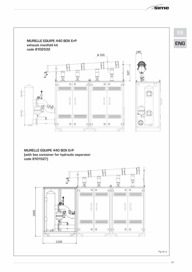
47
ES
ENG
527
ø 200
MURELLE EQUIPE 440 BOX ErPcon kit collettore fumicod. 8102532
MURELLE EQUIPE 440 BOX ErP(con box contenitore per separatore idraulicoe kit sicurezze INAIL cod. 8101527)
1100
1600
180
Fig. 6/a
MURELLE EQUIPE 440 BOX ErPexhaust manifold kitcode 8102532
MURELLE EQUIPE 440 BOX ErP(with box container for hydraulic separatorcode 8101527)

48
180ø 200
565
1100
1600
MURELLE EQUIPE 550 BOX ErP(con box contenitore per separatore idraulicoe kit sicurezze INAIL cod. 8101527)
MURELLE EQUIPE 550 BOX ErPcon kit collettore fumicod. 8102533
Fig. 6/b
MURELLE EQUIPE 550 BOX ErPexhaust manifold kitcode 8102533
MURELLE EQUIPE 550 BOX ErP(with box container for hydraulic separatorcode 8101527)

2.8 TUBES CONNECTING THEHYDRAULIC SEPARATOR KIT(fig. 7 - fig. 7/a)
Tubes connecting the hydraulic separatorkit code 8101532 supplied as option for“MURELLE EQUIPE 220-330 BOX ErP”models it is formed (fig. 7):– System supply f langed section code
6291968– System return f langed section code
6291968– Gaskets, nuts and fastening screws M16– Expansion vessel 8 liters code 6245108
(Preload pressure 1.5 bar – Maximumpressure 10 bar) and connection pipecode 6227661
WARNING: In models “220-330 BOX ErP”the tubes connecting hydraulic separatorkit can be inserted in a specific protectivebox code 8101527 supplied separately.
Tubes connecting the hydraulic separatorkit code 8101533 supplied as option for“MURELLE EQUIPE 440-550 BOX ErP”models it is formed (fig. 7/a):– System supply f langed section code
6291969– System return f langed section code
6291971– Gaskets, nuts and fastening screws M16– Expansion vessel 8 liters code 6245108
(Preload pressure 1.5 bar – Maximumpressure 10 bar) and connection pipecode 6227661
WARNING: In models “440-550 BOX ErP”the tubes connecting hydraulic separatorkit can be inserted in a specific protectivebox code 8101527 supplied separately.
Fig. 7
Fig. 7/a
49
ES
ENG

2.9 RS-485 BOARD (fig. 8)
Each module is supplied with the RS- 485board which allows you to manage the boi-lers in sequence/cascade.The board is placed on the back of the con-trol panel.
2.9.1 MODBUS mode(fig. 8/a)
This mode allows for MODBUS communica-
tion of at least two boilers in cascade and isperformed by requesting another RS-485board provided in the kit code 8092244.
ATTENTION: Communication will occuronly with the MASTER boiler, (boiler withPAR 15 = 0), interpreting the cascade asa single heat capacity generator: P CASCADE = P BOILER x No. BOILERS.
To install the second board, proceed as fol-lows:- Remove the cover and electrically con-
nect the second RS-485 board equippedwith lid to the RS-485 board alreadyinstalled in the MASTER boiler (boiler withPAR 15 = 0) with the wired connectorprovided in the kit.CAUTION: Insert the wired connectorwith caution.
- Set the DIP SWITCH of the new board inMODBUS mode.
- Close the lid of the second board.- Choose the communication configuration
suited to the MODBUS network (PAR 17INST) according to Table PAR 17 INST.
50
x 2
Fig. 8

51
ES
ENG
Fig. 8/a
1 1200 8 No 1 2 1200 8 No 2 3 1200 8 Pari / 1 4 1200 8 2 5 1200 8 Dispari / 1 6 1200 8 2 7 2400 8 No 1 8 2400 8 No 2 9 2400 8 1
10 2400 8 2 11 2400 8 1 12 2400 8 2 13 4800 8 No 1 14 4800 8 No 2 15 4800 8 1 16 4800 8 2 17 4800 8 1 18 4800 8 2 19 9600 8 No 1 20 9600 8 No 2 21 9600 8 1 22 9600 8 2 23 9600 8 1 24 9600 8 2 25 19200 8 No 1 26 19200 8 No 2 27 19200 8 1 28 19200 8 2 29 19200 8 1 30 19200 8 2
PAR 17 INST Baud Rate N° Bit Dati Parità Bit di StopPar 17 INST Baud Rate No. Data Bit Parity Stop Bit
Pari /
Pari /Pari /
Pari / Pari /
Pari /Pari /
Pari /Pari /
Dispari /
Dispari /Dispari /
Dispari /Dispari /
Dispari /Dispari /
Dispari /Dispari /
EvenEven
EvenEven
EvenEven
EvenEven
EvenEven
OddOdd
OddOdd
OddOdd
OddOdd
OddOdd
TABELLA PAR 17 INST/ Tab. PAR 17 INST
CN10
COMUNICAZIONEMODBUSMODBUS
COMMUNICATION
CONNETTORE CABLATO (cod. 6319173)
WIRED CONNECTOR (cod 6319173)
123456
12
3 DIP SWITCHGESTIONE IN MODBUS
MODBUS MANAGEMENT1 2 3
ON
INSTALLER PARAMETER SETTING:
PAR 16 MODBUS ADDRESS
-- = Not enabled
1...31 = Slave from 1 to 31
(ATTENTION: Avoid calling the boiler with the same number assigned to either appliances)
PAR 17 MODBUS CONFIGURATION-- = Not enabled1...30 = Default value: 25(See Table PAR 17 INST)
ATTENTION: Upon setting the parameters, we recommend turning the boiler off and then back on again.

52
Mod
bus
addr
ess
Variable description
Type
Rea
d / W
rite
U.M
.
Min
valu
e
Max
va
lue
Function
Digital variables (COILS)1 Boiler CH Enable/Request D R/W - 0 1 Richiesta riscaldamento zona 12 Boiler DHW Enable D R/W - 0 1 Abilitazione preparazione ACS3 Boiler Water Filling Function D R/W - 0 1 Non usato
32 Boiler CH Mode D R - 0 1 Stato riscaldamento zona 133 Boiler DHW Mode D R - 0 1 Stato preparazione ACS34 Boiler Flame Status D R - 0 1 Stato presenza fiamma35 Boiler Alarm Status D R - 0 1 Stato presenza allarme
Analog/integer variables(REGISTERS Word 16 bit)
1 Boiler CH Primary Setpoint A R/W 0,1°C 20,0 80,0Setpoint riscaldamento zona 1.
Se viene ricevuto un valore fuori rangeequivale a nessun valore ricevuto e vienemantenuta la termoregolazione di caldaia
a punto fisso o a curva climatica.
2 Boiler DHW Primary Setpoint A R/W 0,1°C 20,0 80,0Setpoint circuito primario durante
la preparazione ACS(al posto di PAR 66 caldaia).
Se viene ricevuto un valore fuori range equivalea nessun valore ricevuto e viene utilizzato
il valore di regolazione presente in caldaia.
3 Boiler DHW Setpoint A R/W 0,1°C 10,0 80,0
Setpoint acqua calda sanitaria.Se viene ricevuto un valore fuori range
equivale a nessun valore ricevutoe viene utilizzato il valore
di regolazione presente in caldaia.
4 Outside Temperature MB A R/W 0,1°C -55,0 95,0
Valore di temperatura esterna comunicato via ModBus.Se viene ricevuto un valore fuori range equivale
a nessun valore ricevuto. Nel caso di conflittola caldaia dà la priorità al valore della sonda
ad essa collegata.
5 Boiler CH Curve Slope A R/W 0,1 3,0 40,0Pendenza della curva climatica della zona 1
(utilizzato al posto della curva impostata in caldaia).Se viene ricevuto un valore fuori range equivale
a nessun valore ricevuto e viene utilizzatala curva climatica presente in caldaia.
6 Boiler CH Curve Displacement A R/W 0,1 -5,0 5,0Valore di shift del set ambiente della zona 1
(utilizzato al posto dello shift impostato in caldaia).Se viene ricevuto un valore fuori range equivale
a nessun valore ricevuto e viene utilizzatolo shift presente in caldaia.
64 Boiler DHW Water Temperature A R 0,1°C 0,0 100,0 Temperatura Sonda Acqua calda sanitaria65 Boiler Primary Water Temperature A R 0,1°C 0,0 100,0 Temperatura Sonda Circuito Primario (Mandata)66 Boiler Return Water Temperature A R 0,1°C 0,0 100,0 Temp. Sonda Ritorno Circuito Primario (NO cascata)67 Boiler Flue Gas Temperature A R 0,1°C 0,0 200,0 Temperatura Sonda Fumi (NO cascata)
68 Boiler Relative Modulation Level A R 0,1% 0,0 100,0 Livello Modulazione (0%=Minima Potenza - 100%=Massima Potenza)
69 Boiler Primary Water Pressure A R 0,1 bar 0,0 6,0 Valore Pressione Acqua Circuito Primario
70 Boiler Outside Temperature A R 0,1°C -100,0 100,0 Valore di temperatura esterna lettodalla caldaia tramite la sonda ad essa collegata.
129 Boiler Current Minute I R/W - 0 59 Non usato130 Boiler Current Hour I R/W - 0 23 Non usato131 Boiler Current Day of the Week I R/W - 1 = Lun 7 = Dom Non usato132 Boiler Current Day of the Month I R/W - 1 31 Non usato133 Boiler Current Month I R/W - 1 12 Non usato134 Boiler Current Year I R/W - 2000 2200 Non usato
192 Boiler Alarm Code I R - 0 100Codice numerico visualizzato durante
anomalia caldaia (Master se in cascata).
193 Boiler Slave 1 Alarm Code I R - 0 100
194 Boiler Slave 2 Alarm Code I R - 0 100Codice numerico visualizzato durante
anomalia caldaia slave 2 (Solo cascata)
195 Boiler Slave 3 Alarm Code I R - 0 100
196 Boiler Slave 4 Alarm Code I R - 0 100
Boiler Slave 5 Alarm Code I R - 0 100
199 Boiler Slave 7 Alarm Code I R - 0 100 Codice numerico visualizzato duranteanomalia caldaia slave 7 (Solo cascata)
200 Boiler Combustion Parameter (Par1) I R - 0 199 Valore del PAR 1 in caldaia (Master se in cascata)201 Boiler Hydraulic Parameter (Par2) I R - 0 199 Valore del PAR 2 in caldaia (Master se in cascata)
Codice numerico visualizzato duranteanomalia caldaia slave 4 (Solo cascata)
Codice numerico visualizzato duranteanomalia caldaia slave 5 (Solo cascata)
Codice numerico visualizzato duranteanomalia caldaia slave 6 (Solo cascata)
Request CH zone 1Enable DHW preparationNot used
State CH zone 1
Descrizione /
State preparation DHWState presence flameState presence alarm
Setpoint CH zone 1.If you receive a value out of range
so the value isn’t received and the boiler temperature control is
maintained of fixed point or a temperature curve.
Setpoint CH during ACS preparation(for PAR 66 installer parameters)
If you receive a value out of range the value isn’t received and it is used
the boiler value regulation .
Setpoint ACS.If you receive a value out of range
the value isn’t received and it is used the boiler value regulation.
External value of temperature by MobBus.If you receive a value out of range
the value isn’t received. In case of conflict the boiler will give priority to the value
of the probe connected to it.
Slope of heating curve of zone 1(it is used instead of the curve set in the boiler).If you receive a value out of range
the value isn’t received and it is used the boiler heating curve.
If you receive a value out of range the value isn’t received and it is used
the boiler heating curve.
Shift value of room zone 1 set(it is used instead of the shift set in the boiler).
DHW temperature sensorCH temperature sensor (Delivery)CH temperature sensor (Return) (No cascade)Smoke temperature sensor (No cascade)Modulation level: (0%= minimum power
100%= maximum power) Pressure value water CHOutside temperature read from the boiler
through the probe connected to it
Not usedNot usedNot usedNot usedNot usedNot used
Numeric code shown during boiler error (If Master is in cascade)
Numeric code shown during slave 02 error(Only cascade)
Numeric code shown during slave 07 error(Only cascade)PAR 1 value (If Master is in cascade)PAR 2 value (If Master is in cascade)
TABELLA DELLE VARIABILI MODBUS / MODBUS BOILER VARIABLES LIST
Codice numerico visualizzato duranteanomalia caldaia slave 3 (Solo cascata)
Numeric code shown during slave 03 error(Only cascade)
Numeric code shown during slave 04 error(Only cascade)Numeric code shown during slave 05 error
(Only cascade)
Numeric code shown during slave 06 error(Only cascade)
7 Boiler Delta-T CH A R/W 0,1 10,0 40,0 Valore di setpoint Delta-T (Mandata - Ritorno) Value setpoint Delta-T (Delivery - Return)
Numeric code shown during slave 01 error(Only cascade)
Codice numerico visualizzato duranteanomalia caldaia slave 1 (Solo cascata)
Code01 READ COIL STATUS
03WRITE MULTIPLE COILS
05 (partially supported) WRITE SINGLE COIL04 (partially supported) READ INPUT REGISTER06 (partially supported) WRITE SINGLE REGISTER
NameCOMANDI MODBUS SUPPORTATI / MODBUS COMMANDS SUPPORTED
15
16READ HOLDING REGISTERSWRITE MULTIPLE REGISTERS
197
198 Boiler Slave 6 Alarm Code I R - 0 100

2.10 SYSTEM AVAILABLE HEAD (fig. 9)
The head available of the generator sup-ply/return manifolds vs. the flow rate isshown on the chart of figure 9.
2.10.1 Load loss hydraulic separator
Hydraulic separator load losses are indica-ted in the diagram in fig. 9.WARNING: The hydraulic separator canbe inserted in a specific protective boxcode 8101527 supplied separately.
2.10.2 Hydraulic separator “220-330 BOX ErP” (fig. 10)
The hydraulic separator is supplied separa-tely in a kit code 8101552 complete withgaskets, nuts and fastening screws (figure10).
2.10.3 Hydraulic separator “440-550 BOX ErP” (fig. 10/a)
The hydraulic separator is supplied separa-tely in a kit code 8101553 complete withgaskets, nuts and fastening screws (figure10/a). The plant is supplied with three sup-porting "C" brackets that should be usedonly to rest the compensator onto theground.
53
ES
ENG
Fig. 10
400
500
600
700
PORTATA (m3/h)
5 10 150
100
200
300
∆p (m
bar)
Mur
elle
Equ
ipe800
20
110 B
OX
ErP
22
0 - 2
20
BO
X ErP
330 - 330 BOX ErP440 - 440 BOX ErP
550 - 550 BOX ErP
660 - 660 BOX ErP
Fig. 9
CAPACITY (m3/h)
SYSTEM AVAILABLE HEAD
LOAD LOSS HYDRAULIC SEPARATOR
100
150
5
PORTATA (m3/h)
10 15 20 25 300
50
∆p (m
bar)
35 40 45
200
CAPACITY (m3/h)
C Fig. 10/a

54
TA2 (24 VRAC)
TA1 (24 VRAC)
SB/SA(5 VDC)
SE (5 VDC)
TS (24 VDC)
SM (5 VDC)
SF (5 VDC)
SR (5 VDC)
RS-485 (24 VAC)
OP (24 VAC)
TPA
V
EV 1-2TFU
CR
0...10 VDC
TRA
EA
ER
PI
2.11 ELECTRICAL CONNECTIONS
Each module is supplied with a power cordwhich, if replacement is required, must be
ordered from SIME.230V – 50 Hz single phase voltage isrequired using a fuse protected main swit-ch with at least 3 mm. between contacts.Observe the L – N polarity and grounding
connection.
NOTE: SIME shall not be liable for anydamages to persons and things due tolack of boiler grounding.
2.11.1 Wiring diagram single generator (fig. 11)
KEYF1-2 Fuse (4 AT)TRA Ignition transformerPI Pump high efficiencyV FanEA Ignition electrodeER Detection electrodeEV1-2 Gas valve coilTS Safety thermostatSF Sensor fumesTFU Thermal fuseSM C.H. flow sensorSR C.H. return sensorTPA Pressure transducer
JP1 Selection TA2 or 0-10 VDCTA1 Zone 1 environment thermostatTA2 Zone 2 environment thermostatSB/SA Antifreeze siphon sensorCR Remote control SIME HOME (optional)SE External sensor (optional)OP Programming clock (optional)AR Remote alarmVZ Zone valveAUX Auxiliary connectionRS-485 CASCADE/MODBUS board
NOTE: Connect TA1 to the clamps 7-8 afterhaving removed the bridge.
CONNECTOR SPARE PART CODES:
CN1 code 6319162CN2 code 6319168CN3 code 6319164CN4 code 6316203CN6 code 6316202CN7 code 6316204CN10 code 6319165CN12 code 6319166CN13 code 6319167CN14 code 6319169
Fig. 11
For the range 0 ... 10VDC:- Remove the jumper JP1- Connect the positive signal at terminal 10 of CN6- Connect the negative signal at terminal 4 of the CN4.

55
ES
ENG
Pm
ax
ezze
L
RS
-485
RS
-485
RS
-485
RS
-485
RS
-485
SE
SM
C
(MA
ST
ER
)(S
LA
VE
2)
(SL
AV
E 3
)(S
LA
VE
4)
(SL
AV
E 1
)
RS
-485(S
LA
VE
5)
Fig. 11/a
2.11.2 Electrical connection of modules in sequence/cascade (fig. 11/a)
KEYL LineN NeutralSE External sensorSMC Cascade supply probeRS-485 Cascade management board
NOTICE: The external temperature probe (SE) must be connected to the MASTERboiler and the cascade supply probe (SMC) to the SLAVE 1 boiler.
The SE, SMC probes and the RS-485 board connection cable are suppliedtogether with the modules in the probe kit code 8092250.
The RS-485 board for management in sequence/cascade isplaced at the rear of the control panel of each individual modu-le as shown in the figure.
CONFIGURATION OF CASCADE PARAMETERSSequence/cascade installations must have the following INSTparameter set on all connected boilers:PAR 15 = 0 for the first boiler (MASTER)
1 .... 7 for the other boilers (SLAVE)(Avoid assigning the same number to SLAVEboilers)
Set the following INST parameter if polypropylene smoke col-lectors with a clapet valve are used in sequence/cascadeinstallations:PAR 1 = 8 (for NATURAL GAS boilers)
16 (for PROPANE boilers)
To access the INST parameters, see point 3.3.
In addition, when the number of connected boilers in cascadeis more than two, parameter OEM A1 of the MASTER boilermust be configured as well.To access the OEM parameters press simultaneously the but-tons ( and ) for 2 seconds. Having entered the INST level, press ( and ) simulta-neously for another 2 seconds. At this point insert the accesscode formed by this sequence of INSTALLATOR BUTTONS: “ + / - / < / > / < “. Set the parameter:PAR A1 = Number of cascade generators (3 ... 8)
x 2

56
3 CHARACTERISTICS
3.1 CONTROL PANEL (fig. 12)
5
3
1
2
4
DESCRIPTION OF DISPLAY ICONS
SUMMER MODE ICON
WINTER MODE ICON
D.H.W. MODE ICON
HEATING MODE ICON
GRADED POWER SCALEThe segments of the bar light up in proportion to boiler poweroutput .
2 - DESCRIPTION OF CONTROLS
ON/OFF KEYSON = Electricity supply to boiler is onOFF = Electricity supply to boiler is on but nor ready for
functioning. However, the protection functionsare active.
SUMMER MODE KEYWhen this key is pressed, the boiler functions onlywhen D.H.W. is requested (function not available)
WINTER MODE KEYWhen this key is pressed, the boiler provides heatingand D.H.W.
D.H.W. TEMP KEYWhen this key is pressed, the temperature of theD.H.W. is shown on the display (function not available)
HEATING TEMP KEYThe first time the key is pressed, the temperature ofheating circuit 1 is shown.The second time the key is pressed, the temperatureof heating circuit 2 is shown.The third time the key is pressed, the temperature ofheating circuit 3 is shown (Three zones).
RE-SET KEYThis allows for restoring functioning after a functioninganomaly.
INCREASE AND DECREASE KEYBy pressing this key the set value increases or decrea-ses.
BURNER FUNCTIONING AND BLOCK ICON
DESCRIPTION OF DISPLAY ICONS
CHIMNEY SWEEP ICON
SECONDARY DIGITSThe boiler visualises the value of the pressure of thesystem (correct value is between 1 and 1.5 bar)
3 - KEYS RESERVED FOR THE INSTALLER(access to INST and OEM parameters)
4 - LUMINOUS BARBlue = FunctioningRed = Functioning anomaly
5 - PROGRAMMING CLOCK (optional)Mechanical clock (code 8092228) or digital clock (code8092229) to program heating and water supply.
MAIN DIGITSThe boiler visualises the values set, the stateof anomaly and the external temperature
Fig. 12
PC CONNECTIONTo be used only with the SIME programming kit and onlyby authorised personnel. Do not connect other electro-nic devices (cameras, telephones, mp3 players, etc.)Use a tool to remove the cap and reinsert after use.ATTENTION: Communication port sensitive to electrostatic charges.Before use, it is advisable to touch an earthed metallicsurface to discharge static electricity.
INFORMATION KEYThis key can be pressed several times to view the para-meters.
CHIMNEY SWEEP KEYThis key can be pressed several times to view the para-meters.
DECREASE KEYThis key changes the default settings.
INCREASE KEYThis key changes the default settings.
INTEGRATIVE SOURCES ICON

57
ES
ENG1. Visualizzazione temperatura esterna solo con sonda esterna collegata
2. Visualizzazione temperatura sonda mandata riscaldamento (SM)
3. Visualizzazione temperatura sonda sanitario (SS) solo per caldaie istantanee
4. Visualizzazione temperatura sonda ausiliaria o sonda bollitore (SB)
6. Visualizzazione temperatura riscaldamento riferita al primo circuito
7. Visualizzazione temperatura riscaldamento riferita al secondo circuito
9. Visualizzazione numero giri ventilatore in rpm x 100 (es. 4.800 e 1.850 rpm)
10. Visualizzazione ore di funzionamento del bruciatore in h x 100 (es. 14.000 e 10)
11. Visualizzazione numero di accensioni del bruciatore x 1.000 (es. 97.000 e 500)
5. Visualizzazione temperatura sonda fumi (SF)
8. Visualizzazione corrente di ionizzazione in µA
17. Visualizzazione portata sanitaria flussimetro (es. 18 l/min e 0,3 l/min) o stato flussostato (rispettivamente ON e OFF)
12. Visualizzazione numero totale delle anomalie
13. Contatore accessi parametri installatore (es. 140 accessi)
14. Contatore accessi parametri OEM (es. 48 accessi)
15. Contatore accessi parametri CASCATA OEM (es. 05 accessi)
2. Visualisation of C.H. flow sensor (SM)
3. Visualisation of D.H.W. temperature sensor(SS) only for instantaneous boilers
4. Visualisation of auxiliary temperature sensoror D.H.W. sensor (SB)
6. Visualisation of heating temperature of firstcircuit
7. Visualisation of heating temperature ofsecond circuit
8. Visualisation of ionisation current in µA
10. Visualisation of hours of functioning of the burner in h x 100 (e.g. 14000 and 10)
11. Visualisation of number of times the burner has ignited x 1000 (e.g. 97000 and 500)
12. Visualisation of total number of anomalies
5. Visualisation of smoke temperature sensor(SF)
13. Parameter access counter–Installer (i.e. 140 accesses)
14. Parameter access counter–OEM(i.e. 48 accesses)
3.2 ACCESS TO INSTALLER'S INFORMATION
For access to information for the installer, press the key (3 fig. 14). Every time the key is pressed, the display moves to the next item of
information. If the key is not pressed, the system automatically quits the function. If there is no expansion board (ZONA MIX or INSOL) the
relative info shall not be displayed. List of information:
1. Visualisation of external temperature, onlywith external sensor connected
9. Visualisation fan speed in rpm x 100 (e.g. 4.800 and 1850 rpm)
15. Parameter access counter–CASCADEOEM (i.e. 05 accesses)
17. Visualisation of D.H.W. flowmeter load (i.e. 18 l/min and 0.3 l/min) or flow switch(respectively ON and OFF)

58
20. Visualizzazione valore sonda mandata impianto miscelato con schedino ZONA MIX 1 (ingresso S2)
21. Visualizzazione termostato sicurezza ZONA MIX (ingresso S1) rispettivamente ON e OFF
22. Visualizzazione pompa con schedino ZONA MIX 1 (rispettivamente ON e OFF)
23. Visualizzazione comando apertura valvola con schedino ZONA MIX 1 (rispettivamente ON e OFF)
24. Visualizzazione comando chiusura valvola con schedino ZONA MIX 1 (rispettivamente ON e OFF)
25. Visualizzazione valore della sonda mandata impianto miscelato con schedino ZONA MIX 2
26. Visualizzazione termostato sicurezza con schedino ZONA MIX 2 (ingresso S1) rispettivamente ON e OFF
27. Visualizzazione pompa con schedino ZONA MIX 2 (rispettivamente ON e OFF)
28. Visualizzazione comando apertura valvola con schedino ZONA MIX 2 (rispettivamente ON e OFF)
29. Visualizzazione comando chiusura valvola con schedino ZONA MIX 2 (rispettivamente ON e OFF)
30. Visualizzazione valore temperatura sonda solare S1 con schedino solare INSOL
31. Visualizzazione valore temperatura sonda solare S2 con schedino solare INSOL
32. Visualizzazione valore temperatura sonda solare S3 con schedino solare INSOL
33. Visualizzazione relè solare R1 con schedino solare INSOL (rispettivamente ON e OFF)
34. Visualizzazione relè solare R2 con schedino solare INSOL (rispettivamente ON e OFF)
35. Visualizzazione relè solare R3 con schedino solare INSOL (rispettivamente ON e OFF)
18. Visualizzazione valore sonda ritorno riscaldamento (SR)
19. Visualizzazione valore sonda collettore cascata
40. Visualizzazione valore % comando pompa PWM
36. Visualizzazione stato flussostato solare (rispettivamente ON e OFF)
60. Visualizzazione codice errore ultima anomalia
61. Visualizzazione codice errore penultima anomalia
70. Codice di warning
90. Versione software presente su RS-485 (es. versione 01)
91. Versione software presente su schedino EXP (config. ZONA MIX)
92. Versione software presente su 2° schedino EXP (config. ZONA MIX)
45. Visualizzazione temperatura riscaldamento riferita al terzo circuito
20. Visualisation delivery probe value mixed with board ZONAMIX 1 (input S2)
21. Visualisation safety thermostat ZONA MIX (input S1)respectively ON and OFF
22. Visualisation pump with board ZONA MIX 1 (respectivelyON and OFF)
23. Visualisation valve opening control with board ZONA MIX1 (respectively ON and OFF)
24. Visualisation valve closing control with board ZONA MIX1 (respectively ON and OFF)
25. Visualisation of the plant delivery probe mixed with boardZONA MIX 2
26. Visualisation safety thermostat with board ZONA MIX 2(input S1) respectively ON and OFF
27. Visualisation pump with board ZONA MIX 2 (respectivelyON and OFF)
28. Visualisation valve opening control with board ZONA MIX2 (respectively ON and OFF)
29. Visualisation valve closing opening control with board ZONA MIX 2(respectively ON and OFF)
30. Visualisation solar probe temperature value S1 with solarboard INSOL
31. Visualisation solar probe temperature value S2 with solarboard INSOL
32. Visualisation solar probe temperature value S3 with solarboard INSOL
33. Visualisation solar relay R1 with solar board INSOL (respec-tively ON and OFF)
34. Visualisation solar relay R2 with solar board INSOL (respec-tively ON and OFF)
35. Visualisation solar relay R3 with solar card INSOL (respecti-vely ON and OFF)
18. Visualisation C.H. return sensor value (SR)
19. Visualisation collector probe value
36. Visualisation solar flow meter state (respectively ON andOFF)
40. Visualisation % value pumpcontrol PWM
60. Visualisation of errorcode of last anomaly
61. Visualisation of error codeof penultimate anomaly
70. Code warning
90. Software version on RS-485 (e.g. version 01)
91. Software version on EXP(configuration ZONA MIX)
92. Software version on secondEXP (configuration ZONA MIX)
45. Visualisation of heating temperature ofthird circuit

3.3 ACCESS TO INSTALLER'S PARAMETERS
For access to the installer's parameters,press simultaneously the keys andor 2 seconds (3 fig. 12).For example, the parameter PAR 23 isvisualised on the display of the controlpanel in the following way:
The parameters scrol l forwards andbackwards with the key and andthe default parameters can be changedwith the keys and .The standard visualisation returns automa-tically after 60 seconds, or by pressing oneof the control keys (2 fig. 12) excluded thekey RESET.
3.3.1 Replacing the board or RESETTING parameters
If the electronic board is replaced or reset,it is necessary to configure PAR 1 and PAR2 by associating the following values toeach type of boiler to be able to restart theboiler:
59
ES
ENG
PARAMETERS INSTALLER
FAST CONFIGURATIONPAR DESCRIPTION RANGE UNIT OF INC/DEC DEFAULT
MEASUREMENT UNIT SETTING1 Combustion configuration -- = ND = = “- -”
1 ... 312 Hydraulic configuration -- = ND = = “- -”
1 ... 143 Timetable 2 programmer 1 = DHW + Recirc. pump = = 1
2 = DHW3 = Recirculation pump
4 Pressure transducer disabler 0 = Disabled = = 11 = Enabled 0-4 BAR2 = Enabled 0-6 BAR3 = Enabled 0-4 BAR (NO ALL 09)4 = Enabled 0-6 BAR (NO ALL 09)
5 Assignment of auxiliary relay AUX 1 = Remote supply = = 12 = Recirculation pump3 = Automatic load.4 = Remote alarm NC5 = Heat pump6 = Zone 2 valve
6 Luminous bar indicating presence 0 = Disabled = = 1of voltage 1 = Enabled
7 Allocation of SIME HOME channels 0 = Not assigned = = 11 = Circuit 12 = Three-zone circuit
8 Fan rpm Step ignition 0,0 ... 81 rpmx100 0,1 from 0,1 to 19,9 0,01 from 20 to 81
9 Long chimneys 0 ... 20 % 1 010 Remote control option setting 1 = SIME HOME = = 1
2 = CR 533 = RVS 43.1434 = RVS 46.5305 = RVS 61.843
11 Correction values external sensor -5 ... +5 °C 1 012 Backlighting duration -- = Always sec. x 10 1 3
0 = Never1 ... 199
13 Modulating pump speed -- = None % 10 AuAu = Automatic mod.30...100 = % Settable
modulation14 Setting second input TA -- = Contact TA -- -- --
5...160 = Input 0...10VDC15 Cascade address -- = Not enabled -- 1 --
0 = Master1...7 = Slaves
16 ModBus address -- = Not enabled -- 1 --1...31 = Slaves
17 ModBus communication configuration 1 ... 30 -- 1 2519 Type circuit 0 = Two zones -- -- 0
1 = Three zones
D.H.W. - HEATINGPAR DESCRIPTION RANGE UNIT OF INC/DEC DEFAULT
MEASUREMENT UNIT SETTING20 Minimum heating temperature Zone 1 PAR 64 OEM ... PAR 21 °C 1 2021 Maximum heating temperature Zone 1 PAR 20 ... PAR 65 OEM °C 1 8022 Heating curve slope Zone 1 3 ... 40 -- 1 2023 Minimum heating temperature Zone 2 PAR 64 OEM ... PAR 24 °C 1 2024 Maximum heating temperature Zone 2 PAR 23 ... PAR 65 OEM °C 1 8025 Heating curve slope Zone 2 3 ... 40 -- 1 2026 Minimum heating temperature Zone 3 PAR 64 OEM ... PAR 27 °C 1 2027 Maximum heating temperature Zone 3 PAR 26 ... PAR 65 OEM °C 1 8028 Heating curve slope Zone 3 3 ... 40 -- 1 2029 ∆t heating circuit 10 ... 40 °C 1 2030 Post-circulation heating time 0 ... 199 Sec. 10 3031 Maximum heating capacity 30 ... 100 % 1 10032 Zone 1 pump activation delay 0 ... 199 10 sec. 1 133 Start-up delay 0 ... 10 Min. 1 334 Additional source activation threshold -- , -10 ... 40 °C 1 “- -”35 Boiler antifreeze 0 ... +20 °C 1 336 External sensor antifreeze -5 ... +5 °C 1 -237 Band saturation -- = Disabled % 1 100
flowmeter modulation 0 ... 10038 D.H.W. post-circulation time 0 ... 199 Sec. 1 039 Anti-legionella 0 = Disabled -- -- 0
(only D.H.W tank)) 1 = Enabled
GAS MODEL PAR 1
220 BOX ErPMETHANE 330 BOX ErP 7
(G 20) 440 BOX ErP550 BOX ErP
220 BOX ErPPROPANE 330 BOX ErP 15
(G 31) 440 BOX ErP550 BOX ErP

NOTE: the inside of the upper door of theboiler panel has a label with the valuesthat have to be set for PAR 1 and PAR 2(fig. 19).
3.3.2 Warning
Should the boiler operation not be optimalbut no alarm sets off, press the button
until info 70 and the warning codeassociated to the ongoing event aredisplayed.Once optimal operation is restored, info 70will display: “- -”.Below is the table of warning codes:
60
PARAMETERS INSTALLER
EXPANSION CARD
PAR DESCRIPTION RANGE UNIT OF INC/DEC DEFAULTMEASUREMENT UNIT SETTING
40 Number of expansion boards 0 ... 3 = 1 0
41 Mix valve stroke time 0 ... 199 10 sec. 1 12
42 Priority of D.H.W. over mixed zone 0 = Paralle = = 1
1 = Absolute
43 Floor drying 0 = No activated = = 0
1 = Curve A
2 = Curve B
3 = Curve A+B
44 Type of solar system 1 ... 8 = 1 1
45 ∆t solar collector pump 1 PAR 74 OEM - 1... 50 °C 1 8
46 Solar integration delay “--”, 0 ... 199 Min. 1 0
47 Tmin solar collector “--”, -30 ... 0 °C 1 - 10
48 Tmax solar collector “--”, 80 ... 199 °C 1 120
PARAMETERS RESTORATION
PAR DESCRIPTION RANGE UNIT OF INC/DEC DEFAULTMEASUREMENT UNIT SETTING
49 * Reset default parameters -- , 1 = = =(par 01 - par 02 = “-“)
* In case of difficulty in understanding the current setting or in case of an anomalous or
incomprehensible conduct of the boiler, we suggest to restore the initial values of the parameters
setting PAR 49 = 1 and the PAR 1 and PAR 2 as specified at point 3.3.1.
CASCADE CONNECTION PARAMETERS
When the appliance is installed in sequence/cascade (modularsystem with several generators) it is necessary to set on all theboilers the following INST PAR parameters:PAR 15 = 0 for the first boiler (MASTER)
1 .... 7 for the other boilers (SLAVE)(Avoid assigning the same number to SLAVE boilers)
Set the following INST parameter if polypropylene smoke collec-tors with a clapet valve are used in sequence/cascade installa-tions:PAR 1 = 8 (for NATURAL GAS boilers)
16 (for PROPANE boilers)
In addition, when the number of boilers in cascade is more thantwo, configure the parameters OEM A1 of the MASTER boiler.To access the OEM parameters press simultaneously the buttons( and ) for 2 seconds. Entered in the INST level again presssimultaneously he buttons ( and ) for another 2 seconds. Atthis point insert the access code formed by this sequence ofINSTALLATOR BUTTONS: “ + / - / < / > / < “.
Set the parameter:PAR A1 = Number of cascade generators (3 ... 8)
BOILER PAR 2
Instant with deviator valve 1and flowmeter
Instant with deviator valve, 2flowmeter and solar combination
D.H.W. tank with deviator valve and boiler sensor 3
vers. T (LOW INERTIA)
On board D.H.W. tank withdeviator valve and D.H.W. sensor 4
(LOW INERTIA)
Remote D.H.W. tank with deviator valve and D.H.W. thermostat 5
or heating only vers. T/R boiler(LOW INERTIA)
On board D.H.W. tank withdouble pump and D.H.W. sensor 6
vers. T/R boiler (LOW INERTIA)
On board D.H.W. tank withdouble pump and D.H.W.
thermostat vers. T/R boiler 8(LOW INERTIA)
Heating only withantifreeze sensor 9
(LOW INERTIA)
CODE DESCRIPTION
E0 Reduced capacity operation
(∆t between delivery and return
over 40°C)
E1 Shorted external sensor (SE)
E2 Preheating function active
E3 TBD
E4 TBD
E5 TBD
E6 TBD
E7 TBD
E8 TBD
E9 TBD

3.4 EXTERNAL SENSOR (fig. 13)
If there is an external sensor, the heatingsettings SET can be taken from the climaticcurves according to the external tempera-ture and, in any case, limited to with therange values described in point 3.3 (para-meters PAR 22 for zone 1, PAR 25 for zone2 and PAR 28 for zone 3). The climatic curve to be set can be selectedfrom a value of 3 and 40 (at step 1).Increasing the steepness of the curves offig. 13 will increase the output temperatureas the external temperature decreases.
3.5 CARD FUNCTIONING
The electronic card has the following func-tions:– Antifreeze protection of the heating
and sanitary water circuits (ICE).– Ignition and flame detection system.– Control panel setting for the power and
the gas for boiler functioning.– Anti-block for the pump which is fed for
a few seconds after 24 hours of inacti-vity.
– Antifreeze protection for boilers withan accumulation boiling unit.
– Chimney sweep function which can beactivated from the control panel.
– Temperature which can be shifted withthe external sensor connected. It can be set from the control panel andis active on the heating systems of bothcircuit 1 and circuit 2 and 3.
– Management of 3 independent heatingcircuit systems.
– Automatic regulation of the ignitionpower and maximum heating. Adjustments are managed automati-cally by the electronic card to guaran-tee maximum flexibility in use of thesystem.
– Interface with the following electronicsystems: remote control SIME HOMEcode 8092280/81, thermal regulatorRVS, connected to a management cardof a mixed zone ZONA MIX code8092234, card solar INSOL code8092235 and to board RS-485 formanaging up to 8 boilers in cascade orimplement a communication typeModbus (slave RTU-RS485, ReferenceGuide PI-MBUS-300 Rev. J) code8092243. NOTE: If using RVS 43 set parameter10 to 3 (PAR 10 = 3).
3.6 TEMPERATURE DETECTION SENSOR
Table 4 shows the resistance values of theheating, DHW and exhaust fumes thermi-stors.
If the C.H. flow sensor (SM), C.H. returnsensor (SR) and the exhaust fumes sen-sor (SF) is faulty or open circuit, the boi-
ler will not function.
3.7 ELECTRONIC IGNITION
Ignition and flame detection is controlledby a single electrode on the burner whichguarantees reaction in the case of acci-dental extinction or lack of gas within onesecond.
3.7.1 Functioning cycle
Burner ignition occurs within max. 10seconds after the opening of the gasvalve. Ignition failure with consequent acti-vation of block can be due to:
– Lack of gasThe ignition electrode persists indischarging for max. 10 seconds. If the
burner does not ignite, the anomaly issignalled.This can happen the first time the boi-ler is switched on after a long period ofinactivity due to the presence of air inthe gas pipesIt can be caused by a closed gas tap orby a broken valve coil (the interruptiondoes not allow for opening).
– The electrode does not discharge.In the boiler, only the opening of the gasto the burner can be detected. After10 seconds the anomaly is signalled. Itcan be caused by an interruption in theelectrode wire or if it is incorrectlyanchored to the connection points. Orthe electrode may be earthed or stron-gly worn: it must be replaced. Or the electronic card may be defecti-ve.
– No flame detectedAfter start-up the electrode continuesto discharge even when the burner ison. After 10 seconds, the dischargestops, the burner is switched off and afault is generated.This fault is sometimes caused by theshorting of the electrode cable or by itsimproper fixing to the connectionpoints. The electrode is connected to
61
ES
ENG
TABLE 4 (SM - SR - SF sensors)
Temperature (°C) Resistance (Ω)20 12.09030 8.31340 5.82850 4.16160 3.02170 2.22980 1.669
Fig. 13
ATTENTION: curves are calculated at an ambient temperature of20°C. The user can act on the boiler controls to change the envi-ronment set for which the bend has been calculated by ±5°C.

the earth or badly worn and must bereplaced. The electronic board is faulty.
In the case of a sudden lack of voltage, theburner will immediately switch off. Whenvoltage returns, the boiler will automaticallystart up again.
3.8 HEAD AVAILABLE TO SYSTEM (fig. 14)
Residual head for the heating system isshown as a function of rate of flow in thegraph in fig. 14. The speed of the modula-ting pump system WILO-STRATOS PARA is
set as default (installation parameter PAR13 = Au ).
62
PORTATA (l/h)
0
600
500 30002500200015001000
PR
EVA
LEN
ZA
RES
IDU
A (m
bar)
500
400
100
200
300
700
800
3500 4000
Portat a
(l / h) (mbar)
0
PREVALENZA
400800
1200
782773763748
150020002500300035004000
737708655554448354
WILO-STRATOS PARA
Fig. 14
RES
IDU
AL
HEA
D (
mba
r)
FLOW RATE (l/h)
Residual head(mbar)
Flow rate(l/h)

4.1 GAS VALVE (fig. 16)
The boiler is supplied as standard with agas valve, model SIT 822 NOVAMIX (fig.16).
4.2 GAS CONVERSION (fig. 17)
This operation must be performed byauthorised personnel using original Simecomponents.
To convert from natural gas to LPG or viceversa, perform the following operations–Close the gas cock.–Replace the nozzle with OR (1) and gasket
(2) with the one supplied in the kit.– Inspect all the gas connections using
soapy water or relevant products. Do notuse naked flames.
–Apply the nameplate with the new gasflow layout.
–Calibrate the maximum and minimumpressures of the gas valve following theinstructions provided in paragraph 4.2.2.
4.2.1 New fuel configuration
For access to the installer's parameters,press simultaneously keys and for5 seconds (3 fig. 12). The parameters will scroll up and downwith the keys and . The display pane will show the values of theparameter PAR 1. If the boiler is a methane(G20) model, SET 8 will be displayed:
To change the fuel to propane (G31), it isnecessary to set SET 16, by pressing the
key .
The standard display will automaticallyreturn after 10 seconds. The table below shows the SET settings toenter when the type of gas fuel is changed.
4.2.2 Calibrating the gas valve pressures
Measure the CO2 values with a combustionanalyzer.
Sequence of operations:
1) Press and hold the button down for afew seconds .
2) Press the button for a few seconds .
3) Identify the CO2 values at max. power byadjusting the shutter (5 fig. 16):
4) Press the button for a few seconds .
5) Identify the CO2 values at min. power byadjusting the OFF-SET regulation screw(6 fig. 16):
6) Press the buttons several times tocheck the pressures and chan-ge them if required.
7) Press the button once more to quitthe function.
4.5 MAINTENANCE (fig. 20)
To guarantee functioning and efficiency ofthe appliance, in respect of the legal provi-sions in force, it must be regularly checked;the frequency of the checks depends onthe type of appliance and the installationand usage conditions.In any case, it should be inspected at leastonce a year by a qualified technician.
During maintenance operations, it isimportant to verify that the drip-plate
63
ES
ENG
4 USE AND MAINTENANCE
EV1
EV2
1
2
5
6
Fig. 16
KEY1 Upstream pressure intake2 Downstream pressure intake5 Shutter6 OFF-SET
MAX powerCO2 (Methane) CO2 (Propane)
9,0 ±0,3 10,2 ±0,3
MIN powerCO2 (Methane) CO2 (Propane)
9,0 ±0,3 10,2 ±0,3
21
Fig. 17
GAS MODEL PAR 1
220 BOX ErPMETHANE 330 BOX ErP 8
(G 20) 440 BOX ErP550 BOX ErP
220 BOX ErPPROPANE 330 BOX ErP 16
(G 31) 440 BOX ErP550 BOX ErP

with drain trap contains water (thischeck is particularly important if thegenerator has not been used for exten-ded periods of time).If necessary, the drip plate can be filledusing the tap provided (fig. 20).
4.5.1 Chimney sweep function (fig. 21)
To check boiler combustion, press theinstaller's key for a few seconds. Thechimney sweep function will switch on andwill continue for 15 minutes.From that moment, the boiler will startworking in heating mode at maximumpower, with cut off at 80°C and re-ignitionat 70°C (ATTENTION! Temperature mayreach excessive values when using unpro-tected low temperature plants. Beforeactivating the chimney sweep functionmake sure that the radiator valves oreventual zone valves are open).The test can also be carried out with theboiler working in D.H.W. mode. For this, after activating the chimney sweepfunction, open one or more hot water fau-cets. Under these conditions, the boiler willfunction at maximum power with theD.H.W. circuit kept at between 60°C and50°C. During the test, the hot water fau-cets must remain open.If the key and are pressed duringthe 15 minutes of the chimney sweep func-tion, the boiler will be brought respectivelyto maximum and minimum power.
The chimney sweep function will automa-tically switch off after 15 minutes orwhen the key is pressed again.
4.5.2 Operation floor drying (fig. 22)
The operation floor drying keeps the floorat a pre-established temperature profileand it is activated only for those systems
combined with the mixed zone card ZONAMIX code 8092234. The temperature profiles can be selectedby means of the installer parameter PAR43: 0 = Not activated function1 = Curve setting A2 = Curve setting B3 = Curve setting A + BThe turning off of the function happensclicking on the button OFF (return of PAR43 to the value 0) or automatically at theend of the function. The set of the mixed zone follows the deve-lopment of the selected curve and reachesa maximum of 55°C. During the function all the other heating
demands are ignored (heating, sanitary,antifreeze and chimney sweep). During the functioning the display showsthe remaining days for the completion ofthe function (example mains digits -15 = 15days lack to the end of the function). Thediagram fig. 22 reports the development ofthe curve.
ATTENTION:- Observe the relevant standards and
regulations of the floor manufacturer!- Proper functioning is ensured only
when the plant is correctly installed(hydraulic system, electrical installa-tion, settings)! If not observed, thefloor might get damaged!
64
Fig. 20
Fig. 21
50
45
40
35
30
205 10 15 18 [Tag]0
25
55
A B
1 15 7
X
A + B
1 25
[TVw]
Fig. 22
TVw Flow temperature setpointTag Period in daysx Start dayA Functional heatingB Floor curing heating

4.6 FUNCTIONING ANOMALIES
When there is a functioning anomaly, analarm appears on the display and the blueluminous bar becomes red.Descriptions of the anomalies with relativealarms and solutions are given below:
– LOW WATER PRESSURE ANOMALYALARM 02 (fig. 23/1)If the pressure detected by the transdu-cer is lower than 0.5 bar, the boilerstops and the display shows the alarmALL 02. Lower the knob and turn it anti-clockwise to open until the pressure indi-cated by the transducer is between 1and 1.5 bars.If the load procedure has to be repea-ted several times, it is advisable tocheck that the seal of the heating cir-cuit is intact (check that there are noleaks).
– HIGH WATER PRESSURE ANOMALYALARM 03 (fig. 23/2)If the pressure detected by the transdu-cer is more than 4.8 bar, the boilerstops and the display shows anomalyALL 03.
– C.H. FLOW SENSOR ANOMALYALARM 05 (fig. 23/4)If the C.H. flow sensor (SM) is open orshort circuited, the boiler will not func-tion and the display will show the alarmALL 05.
– FLAME BLOCK ALARM 06 (fig. 23/5)If the flame control has not detected thepresence of the flame after a completeignition sequence, or for any other rea-son the card cannot “see” the flame, theboiler will stop and the display will showthe alarm ALL 06. Press the key of the controls (2) tostart up the boiler again.
65
ES
ENG
Fig. 23/5
2
Fig. 23/1
Fig. 23/2
Fig. 23/4

– SAFETY/LIMIT THERMOSTAT ANO-MALY ALARM 07 (fig. 23/6)If the connection with the safety thermo-stat/limit thermostat is interrupted, theboiler will stop; the flame control willremain waiting to be switched off for oneminute, keeping the system pump on forthat period. If, the thermostat connection is restoredwithin the minute, the boiler will start upworking normally again, otherwise it willstop and the display will show the alarmALL 07.Press the key of the controls (2) tostart up the boiler again.
– PARASITE FLAME ANOMALY ALARM08 (fig. 23/7)If the flame control section recognisesthe presence of flames also in phaseswhen they should not be present, itmeans there is a breakdown in the flamedetection circuit; the boiler will stop andthe display will show anomaly ALL 08.
– WATER CIRCULATION ANOMALYALARM 09 (fig. 23/8)There is no water circulation in the pri-mary circuit. If the anomaly occurs uponfirst request, the boiler performs a maxi-mum of three attempts to assure thepresence of water inside the primary cir-cuit; it then stops showing on the displaythe ALL 09 anomaly. If the anomalyoccurs during normal functioning, thedisplay immediately shows the ALL 09anomaly, keeping the plant pump and theeventual boiler pump, switched on for 1minute. In this case there was a suddenincrease of the boiler inner temperature.Check to see if there is water circulationinside the boiler and check if the pump isoperating properly.To exit the anomaly press the but-ton of the controls (2). If the anomalyreoccurs, request assistance from quali-fied technical personnel.
– AUXILIARY SENSOR ANOMALYALARM 10 (fig. 23/9)When the antifreeze siphon sensor (SA)or D.H.W. sensor L.2000 (SB) is open orshort circuited, the display will show ano-maly ALL 10.
– ACTIVATION OF THE “ALL 13” EXHAU-ST FUMES PROBE (fig. 23/10)The activation of this probe causes theboiler to stop and error message ALL 13to display.Press the key of the controls (2) tostart up the boiler again.
– “ALL 14” EXHAUST FUMES PROBEERROR (fig. 23/11)If the exhaust fumes probes is open orshort-circuited, the boiler stops anderror message ALL 14 displays.
66
Fig. 23/7
Fig. 23/6
2
Fig. 23/9
2
Fig. 23/10
Fig. 23/11
2
Fig. 23/8

– “ALL 15” FAN ERROR (fig. 23/12)The fan speed does not fall within therated speed range. If the error conditions persists for twominutes, the boiler activates a forcedstop for thirty minutes. A new start attempt is repeated afterthe expiry of this interval of time.
– EXTERNAL PROBE ANOMALY “FLASHING” (fig. 23/13)When the external probe (SE) is short-circuited, the display the symbol flashes
. During such anomaly he boiler continuesnormal functioning.
– SAFETY THERMOSTAT INTERVENTIONFIRST MIXED ZONE “ALL 20” (fig.23/14)When it results that the ZONA MIXboard is connected to the boiler thesafety thermostat intervention switchesthe mixed zone plant pump, the mix zonevalve closes and on the display the ano-maly ALL 20. During this anomaly the boiler continuesto function normally.
– DELIVERY PROBE BREAKDOWN ANO-MALY FIRST MIXED ZONE “ALL 21”(fig. 23/15)When it results that the ZONA MIXboard is connected to the boiler and thedelivery probe is open or short circuitedon the display the anomaly ALL 21appears. During this anomaly, the boiler continuesto function normally.
– SAFETY THERMOSTAT INTERVENTIONSECOND MIXED ZONE “ALL 22” (fig.23/16)When it results that the ZONA MIXboard is connected to the boiler The intervention of the safety thermo-stat switches the mixed zone plantpump, the mix zone valve closes and onthe display the anomaly ALL 22. Duringthis anomaly the boiler continues to func-tion normally.
– DELIVERY PROBE BREAKDOWN ANO-MALY SECOND MIXED ZONE “ALL 23”(fig. 23/17)When it results that the ZONA MIXboard is connected to the boiler and thedelivery probe is open or short circuitedon the display the anomaly ALL 23appears. During this anomaly the boilercontinues to function normally.
– SOLAR COLLECTOR SENSOR ANO-MALY (S1) “ALL 24” (fig. 23/18)When the solar probe is open or shortcircuited, on the display the anomaly ALL24 appears. During this anomaly the boi-ler continues to function normally butloses the solar function that is no longeravailable.
– SOLAR PROBE ANOMALY STORAGETANK (S2) “ALL 25” (fig. 23/19)When the solar probe is open or shortcircuited, on the display the anomaly ALL25 appears. During this anomaly the boi-ler continues to function normally butloses the solar function that is no longeravailable.
– AUXILIARY SENSOR ANOMALY (S3)“ALL 26” (fig. 23/20)When the solar probe is open or shortcircuited, on the display the anomaly ALL26 appears. During this anomaly the boi-ler continues to function normally butloses the solar function that is no longeravailable.
– ANOMALY SOLAR APPLICATION COM-PATIBILITY “ALL 27” (fig. 23/21)When the hydraulic configuration is notconsistent with the selection solar appli-cation, on the display the anomaly ALL27 appears. During this anomaly the boi-ler continues to function normally but forthe board is active in the solar anomaly,the function is only available antifreezecollector.
– COMPATIBILITY INPUT (S3) ANOMALYONLY FOR SYSTEM 7 “ALL 28” (fig.23/22)When a probe is connected instead of aclean contact on entry S3 the board ondisplay shows the anomaly ALL 28.During this anomaly the boiler continuesto function normally but for the board isactive in the solar anomaly, the functionis only available antifreeze collector.
– ANOMALY NUMBERS RELATEDBOARD “ALL 29” (fig. 23/23)When one of the board ZONAMIX/INSOL failure or does not communi-cate, the display shows anomaly ALL 29.The boiler functional excluding the func-tion ZONE MIX/INSOL.
67
ES
ENG
Fig. 23/12
Fig. 23/13
Fig. 23/14
Fig. 23/15
Fig. 23/16
Fig. 23/17
Fig. 23/18
Fig. 23/19
Fig. 23/20
Fig. 23/21
Fig. 23/22
Fig. 23/23

– HEATING RETURN PROBE ANOMALY“ALL 30” (fig. 23/24)When the heating return probe (SR) isopen or short-circuited, the displayshows anomaly ALL 30. During suchanomaly the boiler continues normalfunctioning.
– CASCADE DELIVERY SENSOR ANO-MALY “ALL 31” (fig. 23/25)When the cascade del ivery sensor(SMC) is open or shorted, ALL 31 shallbe displayed. During such anomaly, the boiler will conti-nue to operate normally.
– THREE-ZONE SYSTEM CONFIGURA-TION ANOMALY “ALL 32” (fig. 23/26)When the boards connected to the RS-485 are not enough and/or at least oneof them it is not mixing zone board, theboiler stops and anomaly ALL 32 isdisplayed. The boiler restarts when theboiler three-zone system configuration isactivated
– RS-485 BOARD COMMUNICATIONANOMALY IN MODBUS MODE “ALL33” (fig. 23/27)When PAR 16 is different from “- -”andthere is no communication between theboiler board and the RS-485 board inMODBUS mode for at least four minu-tes, the boiler stops and anomaly ALL33 is displayed. The boiler restarts when communicationis restored or when PAR 16 = “- -” is set.
– RS-485 BOARD COMMUNICATION
ANOMALY IN CASCADE MODE “ALL34” (fig. 23/28)When PAR 15 is different from “- -” andthere is no communication between theboiler board and the RS-485 board inCASCADE mode, the boiler stops andanomaly ALL 34 is displayed. The boiler restarts when communicationis restored or when PAR 15 = “- -” is set.
– RS-485 AND RS-485 COMMUNICA-TION ANOMALY “ALL 35” (fig. 23/29)When PAR 15 is different from “- -” andthere is no communication between thetwo RS-485 boards, the boiler stops andanomaly ALL 35 is displayed. The boilerrestarts when communication is resto-red or when PAR 15 = “- -” is set.
CAUTION: In the event ofsequence/cascade connection, errorcodes 70 and 71 will appear on the SIMEHOME remote control display:- ALARM 70
When an anomaly affects cascade ope-ration (cascade delivery sensor ALL31), SIME HOME remote controldisplay will show alarm 70. Verify theanomaly in the cascade.
- ALARM 71When an anomaly occurs in one of themodules and the others keep operatingto the extent permitted, the SIMEHOME remote control display will showalarm 71. Verify the anomaly in thecascade.
68
Fig. 23/29
Fig. 23/24
Fig. 23/25
Fig. 23/27
Fig. 23/28
Fig. 23/26

69
ES
ENG
USER INSTRUCTIONS
WARNINGS– In case of fault and/or incorrect equipment operation, deactivate it, without making any repairs or taking any direct action.
Apply only to qualified technical personnel.
– Boiler installation and any other assistance and/or maintenance activity must be carried out by qualified personnel per-
suant to Standard CEI 64-8. Under no circumstances, the devices sealed by the manufacturer can be tampered with.
– It is absolutely prohibited to block the intake grilles and the aeration opening of the room where the equipment is installed.
– The manufacturer shall not be held liable for any damage caused by improper use of the appliance.
– This appliance is not intended for use by persons (including children) with reduced physical, sensory or mental capabilities,
or lack of experience and knowledge, unless they have been given supervision or instruction concerning use of the appliance
by a person responsible for their safety. Children should be supervised to ensure that they do not play with the appliance.
LIGHTING AND OPERATION
BOILER IGNITION (fig. 24)
The first ignition of the boiler must be car-ried out by qualified technical personnel.Successively, if it is necessary to start upthe boiler again, adhere strictly to the fol-lowing instructions: open the gas tap toallow the flow of the fuel and move themain switch of the system to “ON”. When fuel is fed to the boiler, a sequence ofchecks will be carried out and the displayshows the normal condition of the functio-ning, always indicating the pressure of thesystem. If the blue luminous bar is on, thisindicates the presence of voltage.Press the key of the controls (pos. 2)to activate the functioning. The display willbe as shown in the figure.
N.B.: To the first pressure the keys of thecontrols (2) the display is illuminated, tothe successive pressure the operationmodality is active.
REGULATION OF THE WATER TEMPERA-TURE FOR HEATING (fig. 25)
To set the temperature of the water forheating, press the key of the controls(2). The first time the key is pressed, theSET of heating circuit 1 is selected. Thesecond time it is pressed, the SET of hea-ting circuit 2 is selected. The third time it ispressed, the SET of heating circuit 3 isselected (Three zones). The display will be as shown in the figure.Change the values with the key and
. Standard visualisation will return to thedisplay by pressing the key again, orafter 10 seconds if no key is pressed.
REGULATION OF THE EXTERNAL SENSOR (fig. 25/a)If an external sensor is installed, the value
2
Fig. 24
Fig. 25
Fig. 25/a
2
Circuitoriscaldamento 2
Circuitoriscaldamento 3(impianto trezone)
Heating circuit 2
Heating circuit 3(Three zones)

of the output temperature is automaticallychosen by the system, which quickly adjuststhe environmental temperature on thebasis of the external temperature. If youwish to change the value of the temperatu-re, increasing or decreasing that calcula-ted automatically by the electronic card,proceed as indicated in the preceding para-graph. The level of various correction of avalue of temperature proportional calcula-ted. The display will be as shown in fig.25/a.
TO SWITCH OFF THE BOILER (fig. 24)
In the case of a short absence, press thekey ( ) of the controls (pos. 2). The display will be as shown in the fig. 24. Inthis way, leaving the electricity and the fuelsupply connected, the boiler is protectedfrom frost and from the pump becomingblocked. If the boiler is not used for a pro-longed period, it is advisable to disconnectthe electricity supply, by switching off themain switch of the system, and to close thegas tap and, if low temperatures are expec-ted, to completely empty the hydraulic cir-cuits to avoid pipes being broken by the for-mation of ice in the pipes.
ANOMALIES AND SOLUTIONS
When there is a functioning anomaly, thedisplay shows an alarm and the blue lumi-nous bar becomes red.Descriptions of the anomalies with the rela-tive alarms and solutions are given below:
– ALARM 02 (fig. 27/a)If the water pressure detected is lowerthan 0.5 bar, the boiler will stop and thedisplay will show “ALL 02”.Lower the knob and turn it anti-clockwiseto open until the pressure indicated bythe display is between 1 and 1.5 bars.If it is necessary to repeat the systemloading procedure, it is advisable tocontact qualified technical personnelto check the seal of the heating system(to check whether there are any leaks).
– ALL 03Request assistance from qualifiedtechnical personnel.
– ALL 05Request assistance from qualifiedtechnical personnel.
– ALL 06 (fig. 27/c)Press the key f the controls (2) to
re-start the boiler.If the anomaly persists, request assi-stance from qualified technical person-nel.
– ALL 07 (fig. 27/d)Press the key of the controls (2) tore-start the boiler.If the anomaly persists, request assi-stance from qualified technical person-nel.
– From “ALL 08” to “ALL 10”Request assistance from qualifiedtechnical personnel.
– ALL 13 (fig. 27/e)Press the key of the controls (2) to
re-start the boiler.If the anomaly persists, request assi-stance from qualified technical person-nel.
– ALL 14 and ALL 15Request assistance from qualifiedtechnical personnel.
– “ FLASHING”Request assistance from qualifiedtechnical personnel.
– From “ALL 20” to “ALL 29”Request assistance from qualifiedtechnical personnel.
– From “ALL 30” to “ALL 35”Request assistance from qualifiedtechnical personnel.
– ALL 70 and ALL 71These alarms appear on the SIMEHOME remote control display. Requestassistance from qualified technical per-sonnel.
GAS CONVERSION
If it is necessary to change to a differenttype of gas, request assistance only fromauthorised technical personnel.
MAINTENANCE
Annual maintenance of the applianceshould be planned sufficiently in advance,requesting the assistance of authorisedtechnical personnel.The boiler is supplied with an electric wirefor the electrical power supply which, inthe case of replacement, must be substi-tuted only by another obtained from theconstructor.
DISPOSAL OF THE EQUIPMENT
Once it reaches the end of its operating life,the equipment MUST BE RECYCLED in linewith current legislation.
IT MUST NOT be disposed of together withurban waste.
It can be handed over to recycling centres,if there are any, or to retailers that offerthis service.
Recycling prevents potential damage to theenvironment and health. It allows to reco-ver a number of recyclable materials, withconsiderable savings in terms of moneyand energy.
70
2
Fig. 27/c
2
Fig. 27/d
2
Fig. 27/e
Fig. 27/a

71
APPENDIX
DETALLES DEL PRODUCTO / PRODUCT DETAILS
Murelle Equipe
Clase de eficiencia energética estacional en calefacciónClasse de eficiência energética do aquecimento ambiente sazonal
Potencia térmica (kW)Potência calorífica (kW)
Consumo anual de energía en calefacción (GJ)Consumo anual de energia para aquecimento (GJ)
Eficiencia energética estacional en calefacción (%)Eficiência energética do aquecimento sazonal (%)
C.H. energy efficiency class
Heat output (kW)
C.H. annual energy consumption (GJ)
C.H. seasonal energy efficiency (%)
Potencia sonora dB(A)Potência sonora dB(A)Sound power dB(A)
Con arreglo al anexo IV (punto 1) del Reglamento Delegado (UE) Nº 811/2013 que completa la Directiva 2010/30/UE
Em conformidade com o anexo IV (ponto 1) do regulamento delegado (UE) N.o 811/2013 que complementa a Diretiva 2010/30/UE
Conforming to Annex IV (item 1) of the Delegated Regulations (EU) No. 811/2013 which supplements Directive 2010/30/EU
316
536
91
--
110 BOXErP
211
369
90
--
422
704
91
--
527
871
91
--
Specific precautionary measures to be adopted at the time of assembly, installation or maintenance of the equipment are contained
in the boiler instruction manual
Precauções específicas a tomar no momento da montagem, instalação ou manutenção do aparelho estão contidas no manual de
instruções do aquecedor
En el manual de instrucciones de la caldera se indican las precauciones específicas que se deben adoptar durante el montaje, la
instalación o el mantenimiento del aparato
Classe efficienza energetica stagionale riscaldamento
Potenza termica (kW)
Consumo annuo di energia riscaldamento (GJ)
Efficienza energetica stagionale riscaldamento (%)
Potenza sonora dB(A)
Conforme all’allegato IV (punto 1) del regolamento delegato (UE) N° 811/2013 che integra la Direttiva 2010/30/UE
Specifiche precauzioni da adottare al momento del montaggio, dell’installazione o della manutenzione dell’apparecchio sono contenute
all’interno del manuale istruzioni della caldaia
IT ES PT EN
220 BOXErP
330 BOXErP
440 BOXErP
550 BOXErP
105
201
90
--

72
Información obligatoria para calderas de calefacción de espacios y calderas mixtasInformações a fornecer para aquecedores de ambiente com caldeira e aquecedores combinados com caldeira
Modello / Modelos / Modelos / Model: MURELLE EQUIPE 220 BOX ErP
Caldeira de condensação / Condensing boiler:Yes
Yes
Caldaia di tipo B11/ Caldera de tipo B11/ Caldeira B11 / B11 boiler: No
Equipo de cogeneración para calefacción de espacios:Aquecedor de ambiente com cogeração: No
Equipado con un aparato de calefacción suplementario:Equipado com aquecedor complementar:
No
Apparecchio di riscaldamento misto / Equipo de calefacción mixto:Aquecedor combinado / Combunation heater: No
Elemento / ElementoElemento / item Symbol Value Unit
Potencia térmica nominalPotência calorífica nominal
P n 211 Eficiencia energética estacional de calefacciónEficiência energética do aquecimento ambiente sazonal
s
Para calderas de calefacción de espacios y calderas mixtas: potencia térmica útilAquecedores de ambiente com caldeira e aquecedores combinados equipados com caldeira: energia calorífica útil
Para calderas de calefacción de espacios y calderas mixtas: eficiencia útilAquecedores de ambiente com caldeira e aquecedores combinados equipados com caldeira: eficiência útil
A potencia calorífica nominal y régimen de alta temperatura a
À potência calorífica nominal e em regime de alta temperatura a
P 4
A potencia calorífica nominal y régimen de alta temperatura (*)À potência calorífica nominal e em regime de alta temperatura (*)
4
A 30% de potencia calorífica nominal y régimen de baja temperatura b
A 30% da potência calorífica nominal e em regime de baixa temperatura b
P 1
A 30% de potencia calorífica nominal y régimen de baja temperatura (*)A 30% da potência calorífica nominal e em regime de baixa temperatura (*)
1
Consumo ausiliario di elettricità / Consumos eléctricos auxiliaresConsumos elétricos auxiliares / Auxiliary electricity consumption
Altri elementi / Otros elementosOutros elementos / Other items
A pieno caricoA plena cargaEm plena carga At full load
elmáx
Dispersión térmica en stand-byPerdas de calor em modo de vigília Pstby
A carico parzialrA carga parcialEm carga parcial At part load
elmín
Ignition burner power consumtion
Pign
In modo standby / En modo de esperaEm modo de vigília / In standby mode PSB Emissioni di NOx / Emisiones de Nox
Emissões de Nox / Emission of nitrogen oxides NOx
Per gli apparecchi di riscaldamento misto / Para los calefactores combinados / Aquecedores combinados / For combination heaters:
Profilo di carico dichiaratoPerfil de carga declaradoPerfil de carga declarado / Declared load profile
-- Eficiencia energética de caldeo de aguaEficiência energética do aquecimento de água wh
Consumo diario de electricidadConsumo diário de eletricidade
Qelec Consumo diario de combustibleConsumo diário de combustível Qfuel
Recapiti / Datos de contactoElementos de contacto / Contact details Fonderie Sime S.p.A. Via Garbo 27, 37045 Legnago (VR) ITALIA
a. Régimen de alta temperatura: temperatura de retorno de 60°C a la entrada y 80°C de temperatura de alimentación a la salida del aparato.b. Baja temperatura: temperatura de retorno (a la entrada de la caldera) de 30°C para las calderas de condensación, de 37°C para las calderas de baja
temperatura y de 50°C para las demás calderas.a. Regime de alta temperatura: temperatura de retorno de 60°C à entrada do aquecedor e temperatura de alimentação de 80°C à saída do aquecedor.b. Baixa temperatura: temperatura de retorno de 30°C para as caldeiras de condensação, 37°C para as caldeiras de baixa temperatura e 50°C para os outros
aquecedores (à entrada do aquecedor).
Informazioni da fornire per le caldaie per il riscaldamento d’ambiente e le caldaie miste
Information requirements for boiler space heaters, boiler combination heaters
Caldaia a condensazione / Caldera de condensación:
Caldaia a bassa temperatura / Caldera de baja temperatura:Caldeira de baixa temperatura / Low-temperature boiler:
Apparecchio di cogenerazione per il riscaldamento d’ambiente:
Cogenerator space heater:
Munito di un apparecchio di riscaldamento supplementare:
Equipped with a supplementary heater:
Elemento / ElementoElemento / item
Symbol Value Unit
Potenza termica nominale
Nominal heat output for space heating
Efficienza energetica stagionale del riscaldamento d’ambiente
Seasonal space heating energy efficiencyPer le caldaie per il riscaldamento d’ambiente e le caldaie miste: potenza termica utile
For boiler space heaters and boiler combination heaters: useful heat output
Per le caldaie per il riscaldamento d’ambiente e le caldaie miste: efficienza utile
For boiler space heaters and boiler combination heaters: useful efficiencyAlla potenza termica nominale e a unregime ad alta temperatura a
At nominal heat output and high-temperature regime
Al 30% della potenza termica nominale e a un regime a bassa temperatura
At 30% of nominal heat output and low-temperatura regime
a
b
b
Consumo quotidiano di energia
Daily electricity consumption
a. Regime ad alta temperatura: temperatura di ritorno di 60°C all’entrata e 80°C di temperatura di fruizione all’uscita dell’apparecchiob. Bassa temperatura: temperatura di ritorno (all’entrata della caldaia) per le caldaie a condensazione 30°C, per le caldaie a bassa temperatura 37°C e per le altre caldaie 50°C
a. High-temperature regime means 60°C return temperature at heater inlet and 80°C feed temperature at heater outlet. b. Low-temperature regime means for condensig boilers 30°C, for low-temperature boilers 37°C and for other heaters 50°C return temperature.
Alla potenza termica nominale e a un regimead alta temperatura (*)
At nominal heat output and high-temperature regime (*)Al 30% della potenza termica nominale e aun regime a bassa temperatura (*)
At 30% of nominal heat output and low-temperature regime (*)
Dispersione termica in standbay
Standby heat lossConsumo energetico del bruciatore di accensioneConsumo energético del quemador de encendidoConsumo de energia do queimador de ignição
Efficienza energetica di riscaldamento dell’acqua
Water heating energy efficiencyConsumo quotidiano di combustibile
Daily fuel consumption
(*) Dati di rendimento calcolati con potere calorifico superiore Hs / Datos de rendimiento calculado con el valor calorífico superior Hs Os valores do desempenho calculados com valor calorífico superior Hs / Performance data calculated with gross calorific value Hs
kW
kW
kW
kW
kW
kW
kWh
%
%
%
kW
kW
mg/kWh
%
kWh
210,8
63,24
0,256
0,024
0,007
--
90
87,8
94,9
0,498
0
26
--
--
IT
ES
PT
EN
ANEXO/ATTACHED AA.1MURELLE EQUIPE 220 BOX ErP (cod. 8111271)

73
Información obligatoria para calderas de calefacción de espacios y calderas mixtasInformações a fornecer para aquecedores de ambiente com caldeira e aquecedores combinados com caldeira
Modello / Modelos / Modelos / Model: MURELLE EQUIPE 330 BOX ErP
Caldeira de condensação / Condensing boiler:Yes
Yes
Caldaia di tipo B11/ Caldera de tipo B11/ Caldeira B11 / B11 boiler: No
Equipo de cogeneración para calefacción de espacios:Aquecedor de ambiente com cogeração: No
Equipado con un aparato de calefacción suplementario:Equipado com aquecedor complementar:
No
Apparecchio di riscaldamento misto / Equipo de calefacción mixto:Aquecedor combinado / Combunation heater: No
Elemento / ElementoElemento / item Symbol Value Unit
Potencia térmica nominalPotência calorífica nominal
P n 316 Eficiencia energética estacional de calefacciónEficiência energética do aquecimento ambiente sazonal
s
Para calderas de calefacción de espacios y calderas mixtas: potencia térmica útilAquecedores de ambiente com caldeira e aquecedores combinados equipados com caldeira: energia calorífica útil
Para calderas de calefacción de espacios y calderas mixtas: eficiencia útilAquecedores de ambiente com caldeira e aquecedores combinados equipados com caldeira: eficiência útil
A potencia calorífica nominal y régimen de alta temperatura a
À potência calorífica nominal e em regime de alta temperatura a
P 4
A potencia calorífica nominal y régimen de alta temperatura (*)À potência calorífica nominal e em regime de alta temperatura (*)
4
A 30% de potencia calorífica nominal y régimen de baja temperatura b
A 30% da potência calorífica nominal e em regime de baixa temperatura b
P 1
A 30% de potencia calorífica nominal y régimen de baja temperatura (*)A 30% da potência calorífica nominal e em regime de baixa temperatura (*)
1
Consumo ausiliario di elettricità / Consumos eléctricos auxiliaresConsumos elétricos auxiliares / Auxiliary electricity consumption
Altri elementi / Otros elementosOutros elementos / Other items
A pieno caricoA plena cargaEm plena carga At full load
elmáx
Dispersión térmica en stand-byPerdas de calor em modo de vigília Pstby
A carico parzialrA carga parcialEm carga parcial At part load
elmín
Ignition burner power consumtion
Pign
In modo standby / En modo de esperaEm modo de vigília / In standby mode PSB Emissioni di NOx / Emisiones de Nox
Emissões de Nox / Emission of nitrogen oxides NOx
Per gli apparecchi di riscaldamento misto / Para los calefactores combinados / Aquecedores combinados / For combination heaters:
Profilo di carico dichiaratoPerfil de carga declaradoPerfil de carga declarado / Declared load profile
-- Eficiencia energética de caldeo de aguaEficiência energética do aquecimento de água wh
Consumo diario de electricidadConsumo diário de eletricidade
Qelec Consumo diario de combustibleConsumo diário de combustível Qfuel
Recapiti / Datos de contactoElementos de contacto / Contact details Fonderie Sime S.p.A. Via Garbo 27, 37045 Legnago (VR) ITALIA
a. Régimen de alta temperatura: temperatura de retorno de 60°C a la entrada y 80°C de temperatura de alimentación a la salida del aparato.b. Baja temperatura: temperatura de retorno (a la entrada de la caldera) de 30°C para las calderas de condensación, de 37°C para las calderas de baja
temperatura y de 50°C para las demás calderas.a. Regime de alta temperatura: temperatura de retorno de 60°C à entrada do aquecedor e temperatura de alimentação de 80°C à saída do aquecedor.b. Baixa temperatura: temperatura de retorno de 30°C para as caldeiras de condensação, 37°C para as caldeiras de baixa temperatura e 50°C para os outros
aquecedores (à entrada do aquecedor).
Informazioni da fornire per le caldaie per il riscaldamento d’ambiente e le caldaie miste
Information requirements for boiler space heaters, boiler combination heaters
Caldaia a condensazione / Caldera de condensación:
Caldaia a bassa temperatura / Caldera de baja temperatura:Caldeira de baixa temperatura / Low-temperature boiler:
Apparecchio di cogenerazione per il riscaldamento d’ambiente:
Cogenerator space heater:
Munito di un apparecchio di riscaldamento supplementare:
Equipped with a supplementary heater:
Elemento / ElementoElemento / item
Symbol Value Unit
Potenza termica nominale
Nominal heat output for space heating
Efficienza energetica stagionale del riscaldamento d’ambiente
Seasonal space heating energy efficiencyPer le caldaie per il riscaldamento d’ambiente e le caldaie miste: potenza termica utile
For boiler space heaters and boiler combination heaters: useful heat output
Per le caldaie per il riscaldamento d’ambiente e le caldaie miste: efficienza utile
For boiler space heaters and boiler combination heaters: useful efficiencyAlla potenza termica nominale e a unregime ad alta temperatura a
At nominal heat output and high-temperature regime
Al 30% della potenza termica nominale e a un regime a bassa temperatura
At 30% of nominal heat output and low-temperatura regime
a
b
b
Consumo quotidiano di energia
Daily electricity consumption
a. Regime ad alta temperatura: temperatura di ritorno di 60°C all’entrata e 80°C di temperatura di fruizione all’uscita dell’apparecchiob. Bassa temperatura: temperatura di ritorno (all’entrata della caldaia) per le caldaie a condensazione 30°C, per le caldaie a bassa temperatura 37°C e per le altre caldaie 50°C
a. High-temperature regime means 60°C return temperature at heater inlet and 80°C feed temperature at heater outlet. b. Low-temperature regime means for condensig boilers 30°C, for low-temperature boilers 37°C and for other heaters 50°C return temperature.
Alla potenza termica nominale e a un regimead alta temperatura (*)
At nominal heat output and high-temperature regime (*)Al 30% della potenza termica nominale e aun regime a bassa temperatura (*)
At 30% of nominal heat output and low-temperature regime (*)
Dispersione termica in standbay
Standby heat lossConsumo energetico del bruciatore di accensioneConsumo energético del quemador de encendidoConsumo de energia do queimador de ignição
Efficienza energetica di riscaldamento dell’acqua
Water heating energy efficiencyConsumo quotidiano di combustibile
Daily fuel consumption
(*) Dati di rendimento calcolati con potere calorifico superiore Hs / Datos de rendimiento calculado con el valor calorífico superior Hs Os valores do desempenho calculados com valor calorífico superior Hs / Performance data calculated with gross calorific value Hs
kW
kW
kW
kW
kW
kW
kWh
%
%
%
kW
kW
mg/kWh
%
kWh
316,2
94,86
0,384
0,027
0,011
--
91
87,8
94,9
0,747
0
28
--
--
IT
ES
PT
EN
ANEXO/ATTACHED AA.1MURELLE EQUIPE 330 BOX ErP (cod. 8111272)

74
Información obligatoria para calderas de calefacción de espacios y calderas mixtasInformações a fornecer para aquecedores de ambiente com caldeira e aquecedores combinados com caldeira
Modello / Modelos / Modelos / Model: MURELLE EQUIPE 440 BOX ErP
Caldeira de condensação / Condensing boiler:Yes
Yes
Caldaia di tipo B11/ Caldera de tipo B11/ Caldeira B11 / B11 boiler: No
Equipo de cogeneración para calefacción de espacios:Aquecedor de ambiente com cogeração: No
Equipado con un aparato de calefacción suplementario:Equipado com aquecedor complementar:
No
Apparecchio di riscaldamento misto / Equipo de calefacción mixto:Aquecedor combinado / Combunation heater: No
Elemento / ElementoElemento / item Symbol Value Unit
Potencia térmica nominalPotência calorífica nominal
P n 422 Eficiencia energética estacional de calefacciónEficiência energética do aquecimento ambiente sazonal
s
Para calderas de calefacción de espacios y calderas mixtas: potencia térmica útilAquecedores de ambiente com caldeira e aquecedores combinados equipados com caldeira: energia calorífica útil
Para calderas de calefacción de espacios y calderas mixtas: eficiencia útilAquecedores de ambiente com caldeira e aquecedores combinados equipados com caldeira: eficiência útil
A potencia calorífica nominal y régimen de alta temperatura a
À potência calorífica nominal e em regime de alta temperatura a
P 4
A potencia calorífica nominal y régimen de alta temperatura (*)À potência calorífica nominal e em regime de alta temperatura (*)
4
A 30% de potencia calorífica nominal y régimen de baja temperatura b
A 30% da potência calorífica nominal e em regime de baixa temperatura b
P 1
A 30% de potencia calorífica nominal y régimen de baja temperatura (*)A 30% da potência calorífica nominal e em regime de baixa temperatura (*)
1
Consumo ausiliario di elettricità / Consumos eléctricos auxiliaresConsumos elétricos auxiliares / Auxiliary electricity consumption
Altri elementi / Otros elementosOutros elementos / Other items
A pieno caricoA plena cargaEm plena carga At full load
elmáx
Dispersión térmica en stand-byPerdas de calor em modo de vigília Pstby
A carico parzialrA carga parcialEm carga parcial At part load
elmín
Ignition burner power consumtion
Pign
In modo standby / En modo de esperaEm modo de vigília / In standby mode PSB Emissioni di NOx / Emisiones de Nox
Emissões de Nox / Emission of nitrogen oxides NOx
Per gli apparecchi di riscaldamento misto / Para los calefactores combinados / Aquecedores combinados / For combination heaters:
Profilo di carico dichiaratoPerfil de carga declaradoPerfil de carga declarado / Declared load profile
-- Eficiencia energética de caldeo de aguaEficiência energética do aquecimento de água wh
Consumo diario de electricidadConsumo diário de eletricidade
Qelec Consumo diario de combustibleConsumo diário de combustível Qfuel
Recapiti / Datos de contactoElementos de contacto / Contact details Fonderie Sime S.p.A. Via Garbo 27, 37045 Legnago (VR) ITALIA
a. Régimen de alta temperatura: temperatura de retorno de 60°C a la entrada y 80°C de temperatura de alimentación a la salida del aparato.b. Baja temperatura: temperatura de retorno (a la entrada de la caldera) de 30°C para las calderas de condensación, de 37°C para las calderas de baja
temperatura y de 50°C para las demás calderas.a. Regime de alta temperatura: temperatura de retorno de 60°C à entrada do aquecedor e temperatura de alimentação de 80°C à saída do aquecedor.b. Baixa temperatura: temperatura de retorno de 30°C para as caldeiras de condensação, 37°C para as caldeiras de baixa temperatura e 50°C para os outros
aquecedores (à entrada do aquecedor).
Informazioni da fornire per le caldaie per il riscaldamento d’ambiente e le caldaie miste
Information requirements for boiler space heaters, boiler combination heaters
Caldaia a condensazione / Caldera de condensación:
Caldaia a bassa temperatura / Caldera de baja temperatura:Caldeira de baixa temperatura / Low-temperature boiler:
Apparecchio di cogenerazione per il riscaldamento d’ambiente:
Cogenerator space heater:
Munito di un apparecchio di riscaldamento supplementare:
Equipped with a supplementary heater:
Elemento / ElementoElemento / item
Symbol Value Unit
Potenza termica nominale
Nominal heat output for space heating
Efficienza energetica stagionale del riscaldamento d’ambiente
Seasonal space heating energy efficiencyPer le caldaie per il riscaldamento d’ambiente e le caldaie miste: potenza termica utile
For boiler space heaters and boiler combination heaters: useful heat output
Per le caldaie per il riscaldamento d’ambiente e le caldaie miste: efficienza utile
For boiler space heaters and boiler combination heaters: useful efficiencyAlla potenza termica nominale e a unregime ad alta temperatura a
At nominal heat output and high-temperature regime
Al 30% della potenza termica nominale e a un regime a bassa temperatura
At 30% of nominal heat output and low-temperatura regime
a
b
b
Consumo quotidiano di energia
Daily electricity consumption
a. Regime ad alta temperatura: temperatura di ritorno di 60°C all’entrata e 80°C di temperatura di fruizione all’uscita dell’apparecchiob. Bassa temperatura: temperatura di ritorno (all’entrata della caldaia) per le caldaie a condensazione 30°C, per le caldaie a bassa temperatura 37°C e per le altre caldaie 50°C
a. High-temperature regime means 60°C return temperature at heater inlet and 80°C feed temperature at heater outlet. b. Low-temperature regime means for condensig boilers 30°C, for low-temperature boilers 37°C and for other heaters 50°C return temperature.
Alla potenza termica nominale e a un regimead alta temperatura (*)
At nominal heat output and high-temperature regime (*)Al 30% della potenza termica nominale e aun regime a bassa temperatura (*)
At 30% of nominal heat output and low-temperature regime (*)
Dispersione termica in standbay
Standby heat lossConsumo energetico del bruciatore di accensioneConsumo energético del quemador de encendidoConsumo de energia do queimador de ignição
Efficienza energetica di riscaldamento dell’acqua
Water heating energy efficiencyConsumo quotidiano di combustibile
Daily fuel consumption
(*) Dati di rendimento calcolati con potere calorifico superiore Hs / Datos de rendimiento calculado con el valor calorífico superior Hs Os valores do desempenho calculados com valor calorífico superior Hs / Performance data calculated with gross calorific value Hs
kW
kW
kW
kW
kW
kW
kWh
%
%
%
kW
kW
mg/kWh
%
kWh
421,6
126,48
0,512
0,029
0,014
--
91
87,8
94,9
0,996
0
30
--
--
IT
ES
PT
EN
ANEXO/ATTACHED AA.1MURELLE EQUIPE 440 BOX ErP (cod. 8111273)

75
Información obligatoria para calderas de calefacción de espacios y calderas mixtasInformações a fornecer para aquecedores de ambiente com caldeira e aquecedores combinados com caldeira
Modello / Modelos / Modelos / Model: MURELLE EQUIPE 550 BOX ErP
Caldeira de condensação / Condensing boiler:Yes
Yes
Caldaia di tipo B11/ Caldera de tipo B11/ Caldeira B11 / B11 boiler: No
Equipo de cogeneración para calefacción de espacios:Aquecedor de ambiente com cogeração: No
Equipado con un aparato de calefacción suplementario:Equipado com aquecedor complementar:
No
Apparecchio di riscaldamento misto / Equipo de calefacción mixto:Aquecedor combinado / Combunation heater: No
Elemento / ElementoElemento / item Symbol Value Unit
Potencia térmica nominalPotência calorífica nominal
P n 527 Eficiencia energética estacional de calefacciónEficiência energética do aquecimento ambiente sazonal
s
Para calderas de calefacción de espacios y calderas mixtas: potencia térmica útilAquecedores de ambiente com caldeira e aquecedores combinados equipados com caldeira: energia calorífica útil
Para calderas de calefacción de espacios y calderas mixtas: eficiencia útilAquecedores de ambiente com caldeira e aquecedores combinados equipados com caldeira: eficiência útil
A potencia calorífica nominal y régimen de alta temperatura a
À potência calorífica nominal e em regime de alta temperatura a
P 4
A potencia calorífica nominal y régimen de alta temperatura (*)À potência calorífica nominal e em regime de alta temperatura (*)
4
A 30% de potencia calorífica nominal y régimen de baja temperatura b
A 30% da potência calorífica nominal e em regime de baixa temperatura b
P 1
A 30% de potencia calorífica nominal y régimen de baja temperatura (*)A 30% da potência calorífica nominal e em regime de baixa temperatura (*)
1
Consumo ausiliario di elettricità / Consumos eléctricos auxiliaresConsumos elétricos auxiliares / Auxiliary electricity consumption
Altri elementi / Otros elementosOutros elementos / Other items
A pieno caricoA plena cargaEm plena carga At full load
elmáx
Dispersión térmica en stand-byPerdas de calor em modo de vigília Pstby
A carico parzialrA carga parcialEm carga parcial At part load
elmín
Ignition burner power consumtion
Pign
In modo standby / En modo de esperaEm modo de vigília / In standby mode PSB Emissioni di NOx / Emisiones de Nox
Emissões de Nox / Emission of nitrogen oxides NOx
Per gli apparecchi di riscaldamento misto / Para los calefactores combinados / Aquecedores combinados / For combination heaters:
Profilo di carico dichiaratoPerfil de carga declaradoPerfil de carga declarado / Declared load profile
-- Eficiencia energética de caldeo de aguaEficiência energética do aquecimento de água wh
Consumo diario de electricidadConsumo diário de eletricidade
Qelec Consumo diario de combustibleConsumo diário de combustível Qfuel
Recapiti / Datos de contactoElementos de contacto / Contact details Fonderie Sime S.p.A. Via Garbo 27, 37045 Legnago (VR) ITALIA
a. Régimen de alta temperatura: temperatura de retorno de 60°C a la entrada y 80°C de temperatura de alimentación a la salida del aparato.b. Baja temperatura: temperatura de retorno (a la entrada de la caldera) de 30°C para las calderas de condensación, de 37°C para las calderas de baja
temperatura y de 50°C para las demás calderas.a. Regime de alta temperatura: temperatura de retorno de 60°C à entrada do aquecedor e temperatura de alimentação de 80°C à saída do aquecedor.b. Baixa temperatura: temperatura de retorno de 30°C para as caldeiras de condensação, 37°C para as caldeiras de baixa temperatura e 50°C para os outros
aquecedores (à entrada do aquecedor).
Informazioni da fornire per le caldaie per il riscaldamento d’ambiente e le caldaie miste
Information requirements for boiler space heaters, boiler combination heaters
Caldaia a condensazione / Caldera de condensación:
Caldaia a bassa temperatura / Caldera de baja temperatura:Caldeira de baixa temperatura / Low-temperature boiler:
Apparecchio di cogenerazione per il riscaldamento d’ambiente:
Cogenerator space heater:
Munito di un apparecchio di riscaldamento supplementare:
Equipped with a supplementary heater:
Elemento / ElementoElemento / item
Symbol Value Unit
Potenza termica nominale
Nominal heat output for space heating
Efficienza energetica stagionale del riscaldamento d’ambiente
Seasonal space heating energy efficiencyPer le caldaie per il riscaldamento d’ambiente e le caldaie miste: potenza termica utile
For boiler space heaters and boiler combination heaters: useful heat output
Per le caldaie per il riscaldamento d’ambiente e le caldaie miste: efficienza utile
For boiler space heaters and boiler combination heaters: useful efficiencyAlla potenza termica nominale e a unregime ad alta temperatura a
At nominal heat output and high-temperature regime
Al 30% della potenza termica nominale e a un regime a bassa temperatura
At 30% of nominal heat output and low-temperatura regime
a
b
b
Consumo quotidiano di energia
Daily electricity consumption
a. Regime ad alta temperatura: temperatura di ritorno di 60°C all’entrata e 80°C di temperatura di fruizione all’uscita dell’apparecchiob. Bassa temperatura: temperatura di ritorno (all’entrata della caldaia) per le caldaie a condensazione 30°C, per le caldaie a bassa temperatura 37°C e per le altre caldaie 50°C
a. High-temperature regime means 60°C return temperature at heater inlet and 80°C feed temperature at heater outlet. b. Low-temperature regime means for condensig boilers 30°C, for low-temperature boilers 37°C and for other heaters 50°C return temperature.
Alla potenza termica nominale e a un regimead alta temperatura (*)
At nominal heat output and high-temperature regime (*)Al 30% della potenza termica nominale e aun regime a bassa temperatura (*)
At 30% of nominal heat output and low-temperature regime (*)
Dispersione termica in standbay
Standby heat lossConsumo energetico del bruciatore di accensioneConsumo energético del quemador de encendidoConsumo de energia do queimador de ignição
Efficienza energetica di riscaldamento dell’acqua
Water heating energy efficiencyConsumo quotidiano di combustibile
Daily fuel consumption
(*) Dati di rendimento calcolati con potere calorifico superiore Hs / Datos de rendimiento calculado con el valor calorífico superior Hs Os valores do desempenho calculados com valor calorífico superior Hs / Performance data calculated with gross calorific value Hs
kW
kW
kW
kW
kW
kW
kWh
%
%
%
kW
kW
mg/kWh
%
kWh
527
158,1
0,64
0,032
0,018
--
91
87,8
94,9
1,245
0
32
--
--
IT
ES
PT
EN
ANEXO/ATTACHED AA.1MURELLE EQUIPE 550 BOX ErP (cod. 8111274)

76
NOTES

77
NOTES

78
NOTES


Fonderie Sime S.p.A - Via Garbo, 27 - 37045 Legnago (Vr) Tel. + 39 0442 631111 - Fax +39 0442 631292 - www.sime.it
Do
cu
me
nta
tio
n D
pt.
Fo
nd
eri
e S
ime
S.p
.A.