mohammad reza khedmati et al. engenharia civil: estrutura
TRANSCRIPT
365REM: R. Esc. Minas, Ouro Preto, 60(2): 365-379, abr. jun. 2007
Mohammad Reza Khedmati et al.
AbstractStrength and ductility characteristics of non-
continuously welded stiffened plates under in planeaxial compression are the main focus of this research. Aseries of detailed numerical analyses of stiffened steelplates subjected to in plane compressive load isperformed. Complete equilibrium paths are traced upto collapse for non-linear elastoplastic response ofstiffened plates. Stiffened plates are selected from thedeck structure of real sea-going ships and inlandwaterway vessels. Three different stiffener-to-platewelding procedures are considered: continuous, chainintermittent and staggered intermittent fillet welding.Special attention is paid to the finite element modelingof the fillet welds in either of welding practices. Someavailable tests are simulated applying finite elementmethod.
Keywords: Stiffened plates, intermittent welds, weld gap,buckling load, ultimate strength, ductility, FiniteElement Method (FEM).
A comparative study on three differentconstruction methods of stiffened plates-
strength behaviour and ductilitycharacteristics
(Estudo comparativo do comportamento e ductilidade de placasenrijecidas em três diferentes métodos de construção)
Mohammad Reza KhedmatiAmirkabir University of Technology, 424 Hafez Avenue, Tehran 15914, Iran
E-mail: [email protected]
Khosrow GhavamiDepartment of Civil Engineering, Pontifícia Universidade Católica (PUC-Rio), Rio de Janeiro, Brazil
E-mail: [email protected]
Mehran RastaniPetropars Ltd. No. 10, North Naft Street, Mirdamad Blvd, Tehran, Iran
ResumoO objetivo principal dessa pesquisa é a caracterização
da carga última e ductilidade de placas enrijecidas comsoldas não-contínuas, sujeitas à compressão axial. Paratanto, são realizadas análises numéricas detalhadas nasplacas enrijecidas sob compressão axial com três tipos desolda. Para obtenção da resposta elasto-plástica não-linear, as placas são submetidas a carga de compressãoaté que haja o colapso. As placas enrijecidas selecionadaspara análise, nesse estudo, são oriundas de estruturas daplataforma de navios de grande calado e de embarcaçõesde canal de pequeno calado. São considerados trêsprocedimentos diferentes para soldar o enrijecedor à placa,que são: solda contínua, solda intermitente e soldaalternada por faixa. É dada uma atenção especial para amodelagem de elementos finitos das soldas. Alguns testesdisponíveis, na literatura, foram analisados a partir daaplicação do método de elementos finitos FEM,mostrando a confiabilidade do programa.
Palavras-chave: Placas enrijecidas, solda intermitente,carga de flambagem, resistência última, ductilidade,elementos fintos.
Engenharia Civil: Estrutura em Aço

REM: R. Esc. Minas, Ouro Preto, 60(2): 365-379, abr. jun. 2007366
A comparative study on three different construction methods of stiffened plates-strength behaviour and...
1. IntroductionThin-walled structures are to be
found in many of today’s engineeringdisciplines and it is of particular note thatthey now formulate an increasinggrowing proportion of today’sengineering construction. The quest forlighter more efficient optimised structuralsystems which provide high strengthand stiffness in conjunction with lowstructural weight has served to promotethis trend and also to increase the needfor continued research and developmentfor further advancement in the field. Therange of application of thin-walledstructures has become increasingly morediverse with a considerable deploymentof thin-walled structural elements andsystems found in a wide range of areaswithin the Civil, Mechanical, Chemical,Marine, Aeronautical and Offshore fields.Today’s advanced structural design ofthin-walled lightweight structuralsystems offers a considerable highdegree of structural safety and reliability.
As an example of such thin-walledstructures, ship structures may beexampled which can be modelledbasically as a box girder consisting of anumber of plates stiffened by differentelements, Figure 1. In order to study thestrength of ship hull girder under appliedload conditions, as well as extreme andaccidental limit states, having knowledgeabout the strength behaviour of differentstructural elements consisting of plateand stiffened plate is vital. One of themost important elements within shipstructures as well as other thin-walledstructures is stiffened plates. There aremany research works concerning withthe stiffened plates in which the plateand stiffeners have been assumed to beattached to each other using continuousfillet welds. The buckling and collapsebehaviour of such stiffened plates underdifferent loading conditions has beeninvestigated both numerically [1-8] andexperimentally [9-10].
On the other hand, the necessity toreduce the costs of labour and materialand also to save the weight of ship hulland other thin-walled structures causes
to apply other types of weldingprocedures or practices in theirconstruction. Among the alternativewelding methods or techniques, non-continuous welding is frequently appliedfor the attachment of plates andstiffeners. Unfortunately, there is veryrare works on the response of thestiffened plates incorporating such atype of welding. The only work may bereported here is the one made by Milleret al. [11]. They focused their researchon the mechanism of collapse in specialtype of non-continuously weldedstiffened plates, namely intermittentlywelded serrated stiffened plates, whichis applied in the construction of someinland tank barges operating in USwaters. Serrated stiffeners are producedby cutting channels in half. As a result,two sections of serrated stiffeners areobtained, each of which is connected tothe plate only where the weld exists.Some of the vessels constructed
according to this practice, sufferedcatastrophic hull structural failuresreleasing thousands of gallons of heavyfuel oil into the water. Based on someexperiments, Miller et al. concluded thatthe plate deflects into the serration justbetween the non-continuous weld lines,leading to significant reduction of theultimate strength and subsequentlymuch earlier failure of the whole stiffenedplate.
The objective of this study is toinvestigate the sensitivity of the ultimatestrength and failure mechanism ofstiffened plates constructed by differentwelding methods in common. In line withthis research, a series of elastoplasticlarge deflection analyses is performedon the stiffened plates, which areselected out of the structure of realseagoing ships and inland waterwayvessels. Three different welding methodsare compared with each other focusing
Figure 1 - Ship hull girder as a box-like thin-walled stiffened structure.
367REM: R. Esc. Minas, Ouro Preto, 60(2): 365-379, abr. jun. 2007
Mohammad Reza Khedmati et al.
on their effect on the strength and ductility behaviour ofstiffened plate. Special attention is made on the modelling ofthe fillet welds along continuous or intermittent weld lines.
2. Welding techniques used in shipand offshore construction
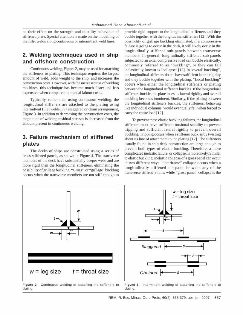
Continuous welding, Figure 2, may be used for attachingthe stiffeners to plating. This technique requires the largestamount of weld, adds weight to the ship, and increases theconstruction costs. However, with the increased use of weldingmachines, this technique has become much faster and lessexpensive when compared to manual labour costs.
Typically, rather than using continuous welding, thelongitudinal stiffeners are attached to the plating usingintermittent fillet welds, in a staggered or chain arrangement,Figure 3. In addition to decreasing the construction costs, themagnitude of welding residual stresses is decreased from theamount present in continuous welding.
3. Failure mechanism of stiffenedplates
The decks of ships are constructed using a series ofcross-stiffened panels, as shown in Figure 4. The transversemembers of the deck have substantially deeper webs and aremore rigid than the longitudinal stiffeners, eliminating thepossibility of grillage buckling. “Gross”, or “grillage” bucklingoccurs when the transverse members are not stiff enough to
Figure 2 - Continuous welding of attaching the stiffeners toplating.
Figure 3 - Intermittent welding of attaching the stiffeners toplating.
provide rigid support to the longitudinal stiffeners and theybuckle together with the longitudinal stiffeners [12]. With thepossibility of grillage buckling eliminated, if a compressivefailure is going to occur in the deck, it will likely occur in thelongitudinally stiffened sub-panels between transversemembers. In general, longitudinally stiffened sub-panelssubjected to an axial compressive load can buckle elastically,commonly referred to as “buckling”, or they can failinelastically, known as “collapse” [12]. In “overall buckling”,the longitudinal stiffeners do not have sufficient lateral rigidityand they buckle together with the plating. “Local buckling”occurs when either the longitudinal stiffeners or platingbetween the longitudinal stiffeners buckles. If the longitudinalstiffeners buckle, the plate loses its lateral rigidity and overallbuckling becomes imminent. Similarly, if the plating betweenthe longitudinal stiffeners buckles, the stiffeners, behavinglike individual columns, would eventually fail when forced tocarry the entire load [12].
To prevent these elastic buckling failures, the longitudinalstiffeners must have sufficient torsional stability to preventtripping and sufficient lateral rigidity to prevent overallbuckling. Tripping occurs when a stiffener buckles by twistingabout its line of attachment to the plating [12]. The stiffenersusually found in ship deck construction are large enough toprevent both types of elastic buckling. Therefore, a morecomplicated inelastic failure, or collapse, is more likely. Similarto elastic buckling, inelastic collapse of a gross panel can occurin two different ways. “Interframe” collapse occurs when alongitudinally stiffened sub-panel between any of thetransverse stiffeners fails, while “gross panel” collapse is the

REM: R. Esc. Minas, Ouro Preto, 60(2): 365-379, abr. jun. 2007368
A comparative study on three different construction methods of stiffened plates-strength behaviour and...
failure of both the longitudinal andtransverse members. Due to the minimumscantling requirements in the rules ofclassification societies, for example [13],the risk of gross panel collapse isminimized, making inelastic interframecollapse the likely failure mode for atypical longitudinally framed decks.
4. Characteristics offinite element analysis4.1 FEA code
All FEA calculations have beenperformed applying ADINA commercialFEA code [14], which has adequateability and accuracy to perform anonlinear finite element analysis inelastoplastic range with due allowancesfor large deflections and initialimperfections. The algorithm of ADINAcode is based on the automatic-stepincremental solution of nonlinear finiteelement equations of the static analysisusing the load displacement control(LDC) method. Such a method can beused to find the nonlinear equilibriumpath of a model from pre- and post-buckling steps until its collapse. The LDCmethod of the ADINA code automaticallyselects the proper iteration method toachieve the quick convergence.
4.2 FE models4.2.1 Stiffened plate underlongitudinal in plane compression
Figure 5 shows a typical stiffenedpanel and the FE model (shaded area).
Figure 4 - Deck structural elements.
Figure 5 - Typical longitudinally stiffened panel and the extent of the FE model.
Figure 6 - Eight-nodded isoparametricquadrilateral element for thick and thinshells.
Both the plate and the stiffener aremodelled with eight-noddedisoparametric quadrilateral shell elements(Figure 6). This element is found to bethe most effective one for the linear andnonlinear analysis of general shellstructures with a high predictivecapability, [16-17]. Fillet welds are alsomodelled with eight-nodded shellelements with the thickness equal to thethroat of the fillet weld. For any element,
3 x 3 Gauss integration points in the r-splane, Figure 7, and two points throughthe shell element thickness are taken intoaccount. Also at the plate-to-stiffenerjunctions, it is assumed that the shellelements of the fillet welds are connectedto those of the plate panel and the stiffenerwith some rigid elements, Figure 8.
The material behaviour of all shellelements is assumed to be elastic-perfectly plastic. Von Mises yield

369REM: R. Esc. Minas, Ouro Preto, 60(2): 365-379, abr. jun. 2007
Mohammad Reza Khedmati et al.
criterion is assumed in the FE analyses.The mesh division of the model is fineenough to capture the buckling andultimate strengths of the stiffenedpanels. However, finer meshes are usednear welded parts of the FE model. Atypical FE model with the mesh divisionsis shown in Figure 9. Table 1demonstrates the state of the boundaryconditions of the model.
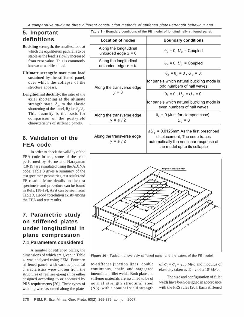
4.2.2 Stiffened plate undertransverse in planecompression
Figure 10 shows a typical stiffenedpanel with a transverse framing system,which is applied in the most inlandwaterways vessels. The FE model isshown in that figure by the shaded area.Boundary conditions imposed on themodel are described in Table 2. A typicalFE model with the mesh divisions isshown in Figure 11.
4.3 Initial geometricimperfections
In the ultimate strengthcalculations, the collapse load cansignificantly depend on shape and theamplitude of initial geometricimperfections as a result of post-weldingdistortion. In this study both theamplitude and geometric shape of thepost-welding distortions includingbuckling deformation caused by residualstresses of the fillet welds due to
Figure 7 - Example of integration point labelling for rectangular shell element.
Figure 8 - Rigid elements at the plate-to-stiffener junction. Figure 9 - Typical FE model with the mesh divisions for a longitudinally stiffened panel.
fabrication process as an initialimperfection on the stiffened plate aretaken in to consideration. However, thisassumption for intermittent fillet weldsleads to somewhat a conservativedesign, as this type of welds producemuch smaller residual compressivestresses in plate panel than continuousfillet welds. In the ultimate strengthcalculations, the collapse load cansignificantly depend on initial geometric
imperfections. Thus, an eigen-valueanalysis is carried out by ADINA. Forthis purpose, a linearised elastic bucklinganalysis is performed first, and thensuperimposed on the geometry of theFE model, as a coordinate perturbationproportional to the buckling modeshapes. Finally, the collapse analysis iseffectively achieved by using the LDCsolution scheme on the model of thegeometrically imperfect stiffened panel.
REM: R. Esc. Minas, Ouro Preto, 60(2): 365-379, abr. jun. 2007370
A comparative study on three different construction methods of stiffened plates-strength behaviour and...
5. ImportantdefinitionsBuckling strength: the smallest load at
which the equilibrium path fails to bestable as the load is slowly increasedfrom zero value. This is commonlyknown as a critical load.
Ultimate strength: maximum loadsustained by the stiffened panel,over which the collapse of thestructure appears.
Longitudinal ductility: the ratio of theaxial shortening at the ultimatestrength state, δp, to the elasticshortening of the panel, δe; i.e. δp/ δe.This quantity is the basis forcomparison of the post-yieldcharacteristics of stiffened panels.
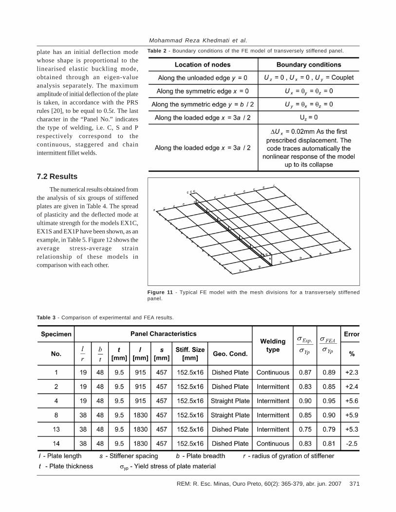
6. Validation of theFEA code
In order to check the validity of theFEA code in use, some of the testsperformed by Horne and Narayanan[18-19] are simulated using the ADINAcode. Table 3 gives a summary of thetest specimen geometries, test results andFE results. More details on the testspecimens and procedure can be foundin Refs. [18-19]. As it can be seen fromTable 3, a good correlation exists amongthe FEA and test results.
7. Parametric studyon stiffened platesunder longitudinal inplane compression7.1 Parameters considered
A number of stiffened plates, thedimensions of which are given in Table4, was analysed using FEM. Fourteenstiffened panels with various practicalcharacteristics were chosen from thestructures of real sea-going ships eitherdesigned according to or approved byPRS requirements [20]. Three types ofwelding were assumed along the plate-
Table 1 - Boundary conditions of the FE model of longitudinally stiffened panel.
Figure 10 - Typical transversely stiffened panel and the extent of the FE model.
to-stiffener junction lines: doublecontinuous, chain and staggeredintermittent fillet welds. Both plate andstiffener materials are assumed to be ofnormal strength structural s teel(NS), with a nominal yield strength
of σy = σ0 = 235 MPa and modulus ofelasticity taken as E = 2.06 x 10⁵ MPa.
The size and configuration of filletwelds have been designed in accordancewith the PRS rules [20]. Each stiffened
371REM: R. Esc. Minas, Ouro Preto, 60(2): 365-379, abr. jun. 2007
Mohammad Reza Khedmati et al.
plate has an initial deflection modewhose shape is proportional to thelinearised elastic buckling mode,obtained through an eigen-valueanalysis separately. The maximumamplitude of initial deflection of the plateis taken, in accordance with the PRSrules [20], to be equal to 0.5t. The lastcharacter in the “Panel No.” indicatesthe type of welding, i.e. C, S and Prespectively correspond to thecontinuous, staggered and chainintermittent fillet welds.
7.2 ResultsThe numerical results obtained from
the analysis of six groups of stiffenedplates are given in Table 4. The spreadof plasticity and the deflected mode atultimate strength for the models EX1C,EX1S and EX1P have been shown, as anexample, in Table 5. Figure 12 shows theaverage stress-average strainrelationship of these models incomparison with each other.
Figure 11 - Typical FE model with the mesh divisions for a transversely stiffenedpanel.
Table 2 - Boundary conditions of the FE model of transversely stiffened panel.
Table 3 - Comparison of experimental and FEA results.

REM: R. Esc. Minas, Ouro Preto, 60(2): 365-379, abr. jun. 2007372
A comparative study on three different construction methods of stiffened plates-strength behaviour and...
Table 4 - Geometric characteristics and summary of results obtained through FEA for longitudinally stiffened panels.

373REM: R. Esc. Minas, Ouro Preto, 60(2): 365-379, abr. jun. 2007
Mohammad Reza Khedmati et al.
7.3 Evaluation of effects ofdifferent quantities on theultimate strength7.3.1 Effect of b / t
Figure 13 represents therelationship between non-dimensionalultimate strength of the stiffened plates
having a / b = 4, b / t = 47&65.2 andcolumn slenderness, λ. As it can beobserved, the variation in the ratio b / thas a negligible effect (less than 5%) onthe average decrease of the strength ofthe stiffened plates in any type ofwelding. The same result is observed forthe other values of b / t.
7.3.2 Effect of a / b
As can be seen from Figure 14, forthe stiffened plates with a / b = 3, forwhich the elastic buckling modecoincides with the stable mode, thehighest amount of ultimate strength isobtained for various types of welding incomparison with the other aspect ratiosof stiffened plates (a / b = 2 & 4).
Table 5 - Plotted FEA results for the models EX1C, EX1S and EX1P under longitudinal compression.

REM: R. Esc. Minas, Ouro Preto, 60(2): 365-379, abr. jun. 2007374
A comparative study on three different construction methods of stiffened plates-strength behaviour and...
Figure 12 - Average stress-averagestrain relationship of the models EX1C,EX1S and EX1P under longi tudinalcompression.
Figure 13 - Effect of b / t on the ultimate strength of the stiffened plates with varioustypes of welding (a / b = 4, b / t = 47 & 62.5).
Figure 14 - Effect of a / b on the ultimate strength of the stiffened plates with varioustypes of welding (b / t = 47, a / b = 2,3,4).
7.3.3 Effect of stiffener section
Comparison of the results in Table4 indicates that the stiffened plate withflat bar stiffener gives a lower ultimatestrength value than those panels withthe angle and bulb flat stiffeners due tolow torsional rigidity of this type ofcross-section, for any type of welding.
7.4 Sensitivity analysis onthe ultimate strength ofstiffened plates7.4.1 Ultimate strength versuscolumn slenderness
It can be seen from Figure 15 thatthe difference in the ultimate strengthbetween continuously welded platesstaggered intermittently welded ones islower (0.7-2.7%) in general, than thatbetween continuously welded platesstaggered intermittently welded ones(1.7-4.5%). Also with the increase in thevalues of column slenderness, thestiffened plates with chain intermittenttype of welding exhibit less strength thanthose with staggered intermittent typeof welding, both in regard to the samecases but with continuous type ofwelding.
Figure 15 - Differences in the ultimate strength of the stiffened plates with varioustypes of welding as a function of λ.

375REM: R. Esc. Minas, Ouro Preto, 60(2): 365-379, abr. jun. 2007
Mohammad Reza Khedmati et al.
7.4.2 Ultimate strength versus plateslenderness
It is interesting to note, from Figure16, that with the increase in the columnslenderness, the ultimate strength ofstiffened plates with chain intermittenttype of welding drops rapidly respect tothe same stiffened plates withcontinuous type of welding. Also it isobserved that the ultimate strength doesnot change much as a function of columnslenderness, for the cases of stiffenedplates with staggered intermittent andcontinuous types of welding.
7.4.3 Comparisons with PRS rules
Figure 17 demonstrates acomparison of all numerical results withstrength curves proposed by PRS rules.Thick solid curve represents theJohnson-Ostenfeld parabola, which isused by PRS rules [20] as a basic criterionfor the buckling control of longitudinallystiffened plates. The thin solid curverefers to the allowable buckling stressobtained by applying the factor η = 0.85used for such stiffened plates. It seemsreasonable to modify the allowable curve,as an acceptable design curve forstiffened plates with λ < 0.4, the value ofthe usage factor η, should be changedfrom 0.85 to 0.8. The dashed line in Figure17 shows the modified design curve.
7.5 Sensitivity analysis onthe longitudinal ductility ofstiffened plates7.5.1 Effect of stiffener type
The values of longitudinal ductilityfor the plates stiffened with flat-bar areabout 30% lower than those for the platesstiffened with bulb or angle-bar, for anytype of welding, Table 4. Also this resultindicates low post-yield reserve strengthobtained by using flat-bar stiffeners.
7.5.2 Effect of b / tIt is observed from Figure 18 that
with increase in b/t, the longitudinal
Figure 16 - Differences in the ultimate strength of the stiffened plates with varioustypes of welding as a function of b / t.
Figure 17 - Comparison of all numerical results with strength curves proposed by PRS rules.
Figure 18 - Longitudinal ductility of stiffened plates with λ≈0.3 against the plateslenderness b / t.

REM: R. Esc. Minas, Ouro Preto, 60(2): 365-379, abr. jun. 2007376
A comparative study on three different construction methods of stiffened plates-strength behaviour and...
ductility of the stiffened plates reducesfor each type of welding. Thelongitudinal ductility of the stiffenedplates with b / t within the range of 47-50is almost equal for any type of welding.In regard to the stiffened plates withb / t < 47, longitudinal ductility of thestiffened plates with chain intermittentwelding is a little greater than that ofcorresponding plates with continuousand staggered intermittent welding. Inthe region b / t >50, the staggeredintermittently welded plates have thehighest ductility in comparison with thecontinuously and chain intermittentlywelded plates.
7.5.3 Effect of column slenderness
Analyzing the ductility curvesrepresented in Figure 19, the followingstatements can be drawn:
In stiffened plates with λ < 0.37, theductility of continuously welded platesis higher than that of the intermittentlywelded ones. The difference between theductility of continuously weldedstiffened plates and chain intermittentlywelded ones grows with decreasing thecolumn slenderness.
Although, for any columnslenderness, the ductility ofcontinuously welded stiffened plates isgreater than that of staggeredintermittently welded ones, thedifference between them is rather small.
In stiffened plates with λ > 0.37, theductility of chain intermittently weldedplates is higher than that of thecontinuously or staggered intermittentlywelded ones. This indicates that thechain intermittently welded slenderstiffened plates provide a more post-yield reserve strength than the others.
The ductility of stiffened plateswith continuous or staggeredintermittent welding decreases while thecolumn slenderness value increases,whereas in respect with the chainintermittently welded, it accompanieswith an increasing tendency.
8. Parametric studyon stiffened platesunder transverse inplane compression8.1 Parameters considered
In order to analyse the stiffenedplates with transverse framing systemsubjected to in plane compressionparallel to the smaller dimension of theplate field, three panels with variouscharacteristics have been chosen asgiven in the Table 6. These panels werechosen from the structures of threeinland waterways vessels withtransverse framing system, which havebeen designed according to PRSrequirements [21]. Other parametersconsidered here are the same as thosementioned in Sec. 7.1.
8.2 ResultsThe numerical results obtained from
the analysis of three groups of stiffenedplates are given in columns 8 and 9 ofTable 6. The spread of plasticity and thedeflected mode at ultimate strength forthe models T3C, T3S and T3P have been
shown, as an example, in Table 7. Figure20 shows the average stress-averagestrain relationship of these models incomparison with each other.
8.3 Dominant parameters onthe ultimate strength
In transversely stiffened panels, thestiffener is applied in order to force anodal line for the buckled state of thepanel, and thus to prohibit the overallbuckling of the stiffened panel. Since theaspect ratio of the panels in such a caseis usually less than 1.0, the primarybuckling mode consists of a single half-wave pattern. The middle portion of theplate receiving little support from thestiffened side buckles like a wide column,and the ultimate strength of such a panelmay be estimated according to theultimate strength of a wide free plate. Thecentral part of the plate is similar to aneccentrically loaded wide column(b→∞), and with increasing load thestress in this part may be estimatedaccording to the ultimate strength of awide column. As the load is furtherincreased, this part becomes wider, butthe ultimate strength level remainsconstant. So only the stresses in the side
Figure 19 - Longitudinal ductility of stiffened plates with b / t = 42-62.5 against thecolumn slenderness λ.

377REM: R. Esc. Minas, Ouro Preto, 60(2): 365-379, abr. jun. 2007
Mohammad Reza Khedmati et al.
Table 7 - Plotted FEA results for the models T3C, T3S and T3P under transverse compression.
Table 6 - Geometric characteristics and summary of results obtained through FEA for transversely stiffened panels.

REM: R. Esc. Minas, Ouro Preto, 60(2): 365-379, abr. jun. 2007378
A comparative study on three different construction methods of stiffened plates-strength behaviour and...
strips continue to increase andeventually these strips undergo inelasticbuckling resulting in the panel collapse.
Figure 21 shows that withdecreasing the aspect ratio a/b of thepanel, the ultimate strength oftransversely stiffened plates willdecrease regardless of the type ofwelding. Also it can be observed fromthis figure that the method of weldingdoes not affect significantly on theultimate strength of transverselystiffened panels.
8.4 DuctilityThe calculated ductility in all of the
transversely stiffened panels with anytype of welding given column 9 of Table6 shows an average value of the order of1.2. This indicates a small post-yieldreserve of the strength in comparisonwith the longitudinally stiffened panels.
8.5 Effects of boundaryconditions
The same analysis with differentboundary conditions of stiffeners wasperformed for all stiffened plates. It wasassumed that the stiffeners are free atthe ends and not restrained by weldingconnection, Figure 22. The results(columns 10 and 11 of the table 6) showan average increase of about 6% in thevalues of the ultimate strength, ascompared with the corresponding panelswith stiffeners restrained at their ends.This comparison in the case of the
Figure 20 - Average stress-average strain relationship of the models T3C, T3S andT3P under transverse compression.
Figure 21 - Effect of a / b on the ultimate strength of the transversely stiffened plateswith various types of welding.
Figure 22 - Stiffeners with free ends at the transversely stiffened plates.

379REM: R. Esc. Minas, Ouro Preto, 60(2): 365-379, abr. jun. 2007
Mohammad Reza Khedmati et al.
ductility values, exhibit a significantincrease about 30%.
When the ends of the stiffeners areconsidered as either free or constrained,their fundamental behaviours are almostthe same, but the component modes aredifferent. The interaction between thecomponent modes may accelerate ordecelerate the plastification and thisgreatly influences the resulting ultimatestrength and ductility values of thestiffened plates. Thus, apart from thepractical processes and economicparameters, more ultimate capacity andductility in case of transversely stiffenedpanels of inland waterways vessels, canbe attained when the ends of thestiffeners are free. This can be achievedby passing them through thelongitudinal girders without welding, asdepicted in Figure 22.
8.6 Comparisons with therules
In accordance with therequirements of the PRS rules [21], theextreme stresses in bottom and deckplating of the ship hull girder underoverall bending should not exceed 0.6σYP.From the calculated ultimate strengthvalues (Table 6), it is noted that for anytype of welding, the ratio σult/σYP rangesfrom 0.5 to 0.6 and well below thepermissible stress limit stated above.This leads to the conclusion that thepermissible stress limit as proposed byPRS for transversely stiffened panels isslightly on the unsafe side and it seemsthat the limit of 0.5 σYP would provide amore adequate margin of safety. Thisneeds a further study.
9. ConclusionsA series of detailed numerical
analyses of stiffened steel platessubjected to inplane compressive loadwere performed using ADINA commercialfinite element code. Complete equilibriumpaths were traced up to collapse fornonlinear elastoplastic response ofstiffened plates. Analyzed stiffened
plates were imperfect and their aspect ratio, plate slenderness and column slendernessare changed in a systematic manner. Different types of stiffener were chosen forstiffened plate models, selected from the deck structure of real sea-going ships andinland waterways vessels. Three different stiffener-to-plate welding procedures wereconsidered: continuous, chain intermittent and staggered intermittent fillet welding.
It was found that, in comparison with continuously welded stiffened plates, theultimate strength is much more reduced in case of chain intermittent fillet welds thanthe case of staggered intermittent fillet welds. Also the longitudinal ductility ofstiffened plate with continuous and staggered intermittent welding is decreasingwhile the column slenderness increases, whereas in regard to stiffened plate withchain intermittent welding, the longitudinal ductility is increasing.
Study of the strength and ductility characteristics of stiffened plates constructedby different welding practices, under other in plane or out of plane loads, alone or incombination, may be found useful in safety and reliability assessment of this-walledstructures. These remain as future works.
10. References[1] SHERBOURNE, A.N., LIAW, C.Y., MARSH, C. Stiffened plates in uniaxial compression.
IABSE, 31, p.145, 1971.[2] CARLSEN, C.A. Simplified collapse analysis of stiffened plates. Norwegian Maritime Research,
4. p. 20-36, 1977.[3] MOOLANI, F.M., DOWLING, P.J. Ultimate load behaviour of stiffened plates in compression.
Steel Plates Structures, Crosby Lockwood Staples, London, p. 51-88, 1977.[4] GUEDES SOARES, C., SOREIDE, TH. Behaviour and design of stiffened plates under
predominantly compressive loads. International Shipbuilding Progress, p. 341, 1983.[5] CHAPMAN, J.C., SMITH, C.S., DAVIDSON, P.C., DOWLING, P.J. Recent developments in
the design of stiffened plate structures, Trans. RINA, 1989.[6] BONELLO, M.A., CHRYSSANTHOPOULOS, M.K., DOWLING, P.J. Ultimate strength design of
stiffened plates under axial compression and bending. Marine Structures, 6, p. 533-52, 1993.[7] CHEN, Q., ZIMMERMAN, T.J.E., DeGEER, D., KENNEDY, B.W. Strength and stability
testing of stiffened plate components. Ship Structural Committee Report SSC-399, 1997.[8] GRONDIN, G.Y., ELWI, A.E., CHENG, J.J.R. Buckling of stiffened plates- a parametric study.
Journal of Constructional Steel Research, 50, p.151-175, 1999.[9] GHAVAMI, K. Experimental study of stiffened plates in compression up to collapse. Journal
of Constructional Steel Research, v. 28, n. 2, p. 197-222, 1994. (Special Brazilian Issue,Guest Editor Khosrow Ghavami).
[10] TANAKA, Y., ENDO, H. Ultimate strength of stiffened plates with their stiffeners locallybuckled in compression. Journal of the Society of Naval Architects of Japan, 1988; 164, (inJapanese).
[11] MILLER, M., NADEAU, J., WHITE, G.J. Longitudinally stiffened panels - a comparativeanalysis of the compressive strength of three common construction methods, Proceedings ofSNAME Annual Meeting, 1999.
[12] HUGHES, O.F. (2. nd. ed.) Ship Structural Design, SNAME, Jersey City, NJ, 1988.[13] ABS. Rules for Building and Classing Steel Vessels for Service on Rivers and Intracoastal
Waterways, 2005.[14] ADINA, Version 6.1.4, ADINA R & D, Inc., USA, 1992.[15] BATHE, K.J., DVORKIN, E.N. On the automatic solution of nonlinear finite element
equations. Computers and Structures, v. 17, n.5-6, p.871-879. 1983.[16] DVORKIN, E.N., BATHE, K.J. A continuum mechanics based four-node shell element for
general nonlinear analysis. Engineering Computations, p. 77-88. 1984.[17] BATHE, K.J., DVORKIN, E.N. A formulation of general shell elements- the use of mixed
interpolation of torsional components. Int. J. Num. Meth. In Eng., 22, p. 697-722, 1986.[18] HORNE, M.R., NARAYANAN, R., Ultimate capacity of longitudinally stiffened plates used
in box girders, Proc. Inst. Civ. Engrs, v. 61, n. 2, p.253-280, 1976.[19] HORNE, M.R., NARAYANAN, R., Influence on strength of compression panels of stiffener
section, spacing and welded connection. Proc. Inst. Civ. Engrs, v. 63, n. 2, p.1-20. 1977.[20] POLISH REGISTER OF SHIPPING. Rules for classification and construction of sea-going
ships. Pt.II, Hull, 2002.[21] POLISH REGISTER OF SHIPPING. Rules for classification and construction of inland
waterways vessels. Pt.II, Hull, 2002.
Artigo recebido em 07/12/2006 e aprovado em 07/12/2006.