manual de instruções - avdelmanuals.co.uk · intensificador e caixa de controlo e ... de óculos...
TRANSCRIPT

07536Ferramenta H idro - Pneumát ica
0753
TYPE
Manua l de I ns t ruçõesTraduçâo das i ns t ruções o r ig i na i s

3
Í nd ice
Regras de Segurança 4
EspecificaçõesEspecificações para a Ferramenta 07536 5Especificações para o Intensificador 07531 5
Finalidade de Utilização 6Dimensões da Ferramenta - Modelo 07536 6
Colocação ao ServiçoAbastecimento de ar 7Cursor Pneumáticos 8Para Carregar e Recarregar a Ferramenta 9-10Procedimento de Operação 10
Manutenção da FerramentaDiariamente 11Semanalmente 11Dados de Segurança da massa Moly Lithium EP 3735 11Kit de Manutenção 12
ManutençãoConjunto da Ferramenta de Cursor Pneumático, 13 Intensificador e Caixa de Controlo e Lista de PeçasDesmontagem da 07536-02200 14-15Conjunto Geral e Lista de Peças da 07536-02200 16-17Intensificador 07531-02200 - Manutenção 18Intensificador 07531-02200 - Conjunto Geral e 19Lista de Peças
PreparaçãoDetalhes do óleo 20Dados de Segurança Hyspin® VG 32 e AWS 32 20Procedimento de Preparação 20
Resolução de problemasSintoma, Possível Causa e Solução 21
A política da Avdel UK Limited é de desenvolvimento e melhoramento contínuos de produto e reservámos o direito de alterar as especificações de qualquer produto sem aviso prévio.
GARANTIA LIMITADA
A Avdel oferece a garantia limitada de que os seus produtos estarão isentos de defeitos de fabrico e
materiais que ocorram em condições de operação normal. Esta Garantia Limitada irá depender: (1) do
produto ser instalado, mantido e utilizado de acordo com as instruções e a documentação sobre o produto e
(2) da confirmação, por parte da Avdel , desse defeito, após inspecção e teste. A Avdel oferece a
mencionada garantia limitada por um período de doze (12) meses, a partir da entrega do produto da Avdel
ao comprador directo da Avdel . Em caso de qualquer incumprimento da mencionada garantia, a única
solução será a devolução dos Bens defeituosos para a sua substituição ou reembolso do preço da compra,
ao critério da Avdel . A GARANTIA LIMITADA EXPRESSA E SOLUÇÃO ANTERIORMENTE MENCIONADAS SÃO
EXCLUSIVAS E SUBSTITUEM TODAS AS OUTRAS GARANTIAS E SOLUÇÕES. A AVDEL EXONERA-SE E EXCLUI
ESPECIFICAMENTE QUALQUER GARANTIA IMPLÍCITA DE QUALIDADE, ADEQUAÇÃO A UM FIM OU
COMERCIALIZAÇÃO DO PRODUTO.
4
Regras de Segurança
1 Utilize apenas para a finalidade para que foi concebida.
2 A ferramenta manual e o intensificador foram testados como itens separados e combinados. Estes só devem ser utilizados juntos e em
circunstância alguma para outros fins.
3 Não utilize equipamento com esta ferramenta/máquina que não seja o recomendado e fornecido pela Avdel UK Limited.
4 Qualquer modificação efectuada pelo cliente à ferramenta/máquina, conjuntos de ponta, acessórios ou qualquer equipamento fornecido
por Avdel UK Limited ou seus representantes, será da inteira responsabilidade do cliente. A Avdel UK Limited terá todo o prazer em
aconselhar sobre qualquer modificação proposta.
5 A ferramenta/máquina terá de ser mantida sempre em condição de segurança e inspeccionada a intervalos regulares quanto a danos e
operada por pessoal competente e treinado. Qualquer procedimento de desmontagem será realizado apenas por pessoal formado em
procedimentos Avdel UK Limited. Não desmonte a ferramenta/máquina sem primeiro consultar as instruções de manutenção. Contacte a
Avdel UK Limited com os seus requisitos de formação.
6 A ferramenta/máquina deverá ser sempre operada de acordo com a legislação de Saúde e Segurança pertinente. No R.U. aplica-se a
norma de 1974 “Saúde e Segurança no Trabalho etc.”. Quaisquer perguntas que digam respeito à operação correcta da
ferramenta/máquina e segurança do operador deverão ser feitas directamente à Avdel UK Limited.
7 As precauções a ter em conta ao utilizar esta ferramenta/máquina terão de ser explicadas pelo cliente a todos os operadores.
8 Desligue sempre a linha de ar da entrada da ferramenta/máquina antes de tentar ajustar, montar ou remover o conjunto de ponta.
9 Não opere uma ferramenta/máquina que esteja apontada na direcção de pessoas.
10 Adopte sempre uma posição equilibrada e firme antes de operar a ferramenta/máquina.
11 Assegure-se de que os orifícios de respiro não ficam bloqueados ou cobertos e de que os tubos estão sempre em boa condição.
12 A pressão de funcionamento não deverá exceder as 7 bar – 100 lbf/pol. ao quadrado.
13 A combinação de elemento de fixação, mandril, tamanho de furo e espessura de chapa deverá estar de acordo com as especificações da
Avdel UK Limited.
14 Não opere a ferramenta se esta não estiver equipada com um conjunto de ponta completo, excepto se especificado em contrário.
15 Ao utilizar a ferramenta, é necessário o uso de óculos de protecção, tanto pelo operador como pelas pessoas que se encontram na
proximidade para proteger contra projecção de elementos de fixação, no caso de um elemento de fixação ser colocado "no ar".
Recomendamos a utilização de luvas se existirem arestas ou cantos vivos na aplicação.
16 Tenha cuidado para evitar que roupas soltas, gravatas, cabelo comprido, trapos de limpeza etc. sejam apanhados pelas partes móveis
da ferramenta, esta deverá ser mantida limpa e seca para a melhor agarração possível.
17 Ao transportar a ferramenta de lugar para lugar mantenha as mãos afastadas do gatilho/alavanca para evitar o arranque inadvertido.
18 Contacto excessivo com o óleo hidráulico deverá ser evitado. Para minimizar a possibilidade de irritações da pele, deverá ter cuidado
para lavar muito bem.
Este manual de instruções tem de ser lido pela pessoa que irá instalar, operar ou fazer a manutenção destaferramenta prestando atenção especial às seguintes regras de segurança.
I M P O R T A N T E
Embora um pouco de desgaste e marcação ocorra naturalmente através da utilização normal e correcta de mandris,estes devem ser examinados regularmente quanto a desgaste e marcações excessivas, com atenção especial ao diâmetroda cabeça, à área de agarração das garras posteriores do encabadouro ou este estar muito picado e quaisquer distorçõesde mandril. Os mandris que falham durante a utilização poderão sair forçadamente da ferramenta. É da responsabilidade
do cliente assegurar-se de que os mandris são substituídos antes de apresentarem quaisquer níveis excessivos dedesgaste e sempre antes do número máximo recomendado de colocações. Contacte o seu representante da Avdel que lhedirá qual é esse número medindo a carga de escareação da sua aplicação com uma ferramenta de teste calibrada. Estas
ferramentas também podem ser compradas sob a referência 07900-09080 e são fornecidas com toda a informaçãonecessária para testar neste manual.
5
E s p e c i f i c a ç õ e s P a r a a F e r r a m e n t a 0 7 5 3 6
Espec i f icações Para o In tens i f icador 07531
Espec i f i caçoes
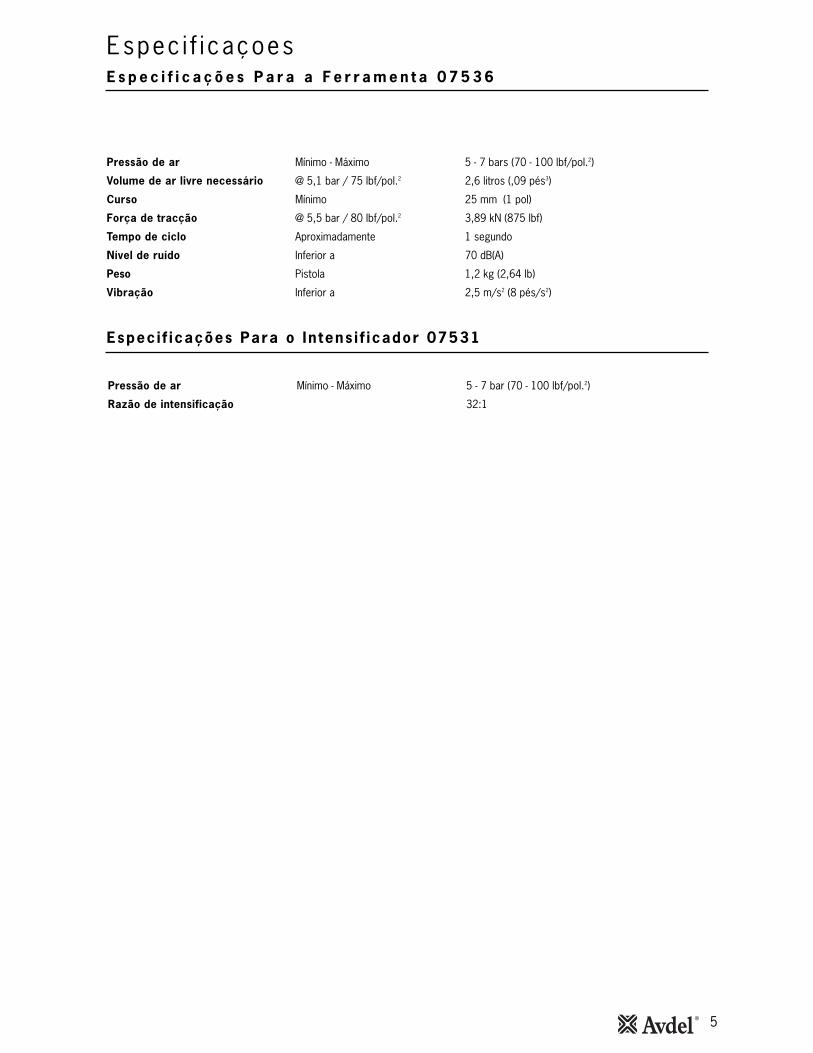
Pressão de ar Mínimo - Máximo 5 - 7 bars (70 - 100 lbf/pol.2)
Volume de ar livre necessário @ 5,1 bar / 75 lbf/pol.2 2,6 litros (,09 pés3)
Curso Mínimo 25 mm (1 pol)
Força de tracção @ 5,5 bar / 80 lbf/pol.2 3,89 kN (875 lbf)
Tempo de ciclo Aproximadamente 1 segundo
Nível de ruído Inferior a 70 dB(A)
Peso Pistola 1,2 kg (2,64 lb)
Vibração Inferior a 2,5 m/s2 (8 pés/s2)
Pressão de ar Mínimo - Máximo 5 - 7 bar (70 - 100 lbf/pol.2)
Razão de intensificação 32:1

6
D i m e n s o e s d a F e r r a m e n t a - M o d e l o 0 7 5 3 6
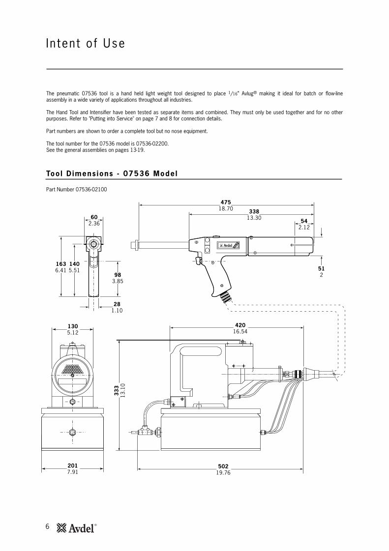
As dimensões que se mostram em negrito são em milímetros. As outras dimensões são em polegadas.
0753
602.36
281.10
983.85
1305.12
47518.70 338
13.30
512
1636.41
1405.51
542.12
2017.91
42016.54
33
313
.10
50219.76
Referência 07536-02100
Finalidade de Utilização
A ferramenta pneumática 07536 é uma ferramenta manual, leve concebida para colocar elementos Avlug® 1/16" tornando-a ideal paramontagem por lotes ou em fluxo numa grande variedade de aplicações em todos os tipos de indústrias.
A ferramenta manual e o intensificador foram testados como itens separados e combinados. Estes só devem ser utilizados juntos enunca para outros fins. Consulte "Colocação ao serviço" na página 7-8 para obter os detalhes sobre as ligações.
A referência da ferramenta para o modelo 07536 é 07536-02200. Consulte os conjuntos gerais nas páginas 13 a 19.
A ferramenta coloca a maior parte dos elementos de fixação de repetição, conforme apresentado na tabela abaixo.
7
A b a s t e c i m e n t o d e A r
Colocação ao Serv iço
86
42
0
10121416
PONTO DO DESPRENDIMENTO DO ABASTECIMENTO PRINCIPAL
TORNEIRA DE FECHAMENTO(UTILIZADA DURANTE A MANUTENCAO DO
FILTRO/REGULADOR UNIDADES DE LUBRIFICACAO
PONTO DE DRENAGEMDO ABASTECIMENTO PRINCIPAL
REGULADOR DE PRESSAO EFILTRO (DRENAR DIARIAMENTE)
MAX
IM
O DE 3 METROS
LUBRIFICADOR
0753
TYPE
~
~
~
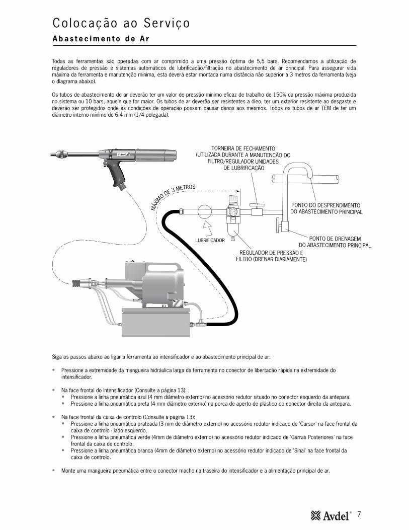
Todas as ferramentas são operadas com ar comprimido a uma pressão óptima de 5,5 bars. Recomendamos a utilização dereguladores de pressão e sistemas automáticos de lubrificação/filtração no abastecimento de ar principal. Para assegurar vidamáxima da ferramenta e manutenção mínima, esta deverá estar montada numa distância não superior a 3 metros da ferramenta (vejao diagrama abaixo).
Os tubos de abastecimento de ar deverão ter um valor de pressão mínimo eficaz de trabalho de 150% da pressão máxima produzidano sistema ou 10 bars, aquele que for maior. Os tubos de ar deverão ser resistentes a óleo, ter um exterior resistente ao desgaste edeverão ser protegidos onde as condições de operação possam causar danos aos mesmos. Todos os tubos de ar TÊM de ter umdiâmetro interno mínimo de 6,4 mm (1/4 polegada).
Siga os passos abaixo ao ligar a ferramenta ao intensificador e ao abastecimento principal de ar:
• Pressione a extremidade da mangueira hidráulica larga da ferramenta no conector de libertação rápida na extremidade dointensificador.
• Na face frontal do intensificador (Consulte a página 13):• Pressione a linha pneumática azul (4 mm diâmetro externo) no acessório redutor situado no conector esquerdo da antepara. • Pressione a linha pneumática preta (4 mm diâmetro externo) na porca de aperto de plástico do conector direito da antepara.
• Na face frontal da caixa de controlo (Consulte a página 13):• Pressione a linha pneumática prateada (3 mm de diâmetro externo) no acessório redutor indicado de 'Cursor' na face frontal da
caixa de controlo - lado esquerdo. • Pressione a linha pneumática verde (4mm de diâmetro externo) no acessório redutor indicado de 'Garras Posteriores' na face
frontal da caixa de controlo.• Pressione a linha pneumática branca (4mm de diâmetro externo) no acessório redutor indicado de 'Sinal' na face frontal da
caixa de controlo.
• Monte uma mangueira pneumática entre o conector macho na traseira do intensificador e a alimentação principal de ar.
8
Cursor Pneumát icos
Colocação ao serv iço
0753
�
TYPE
CURSOR
GARRAS DE PONTA
CANO DAFERRAMENTA
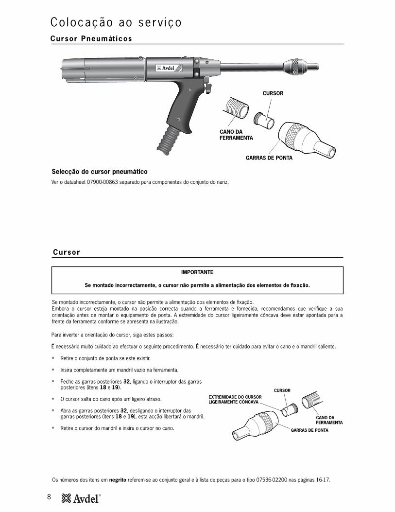
Selecção do cursor pneumático
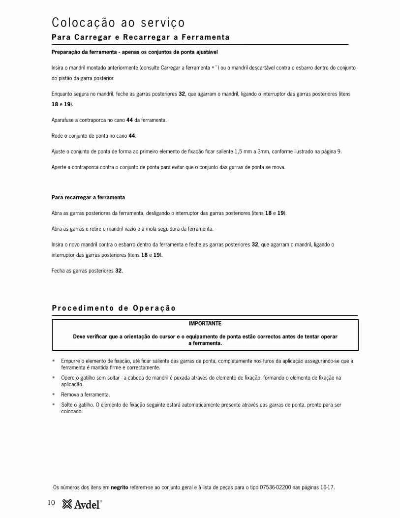
Se montado incorrectamente, o cursor não permite a alimentação dos elementos de fixação.Embora o cursor esteja montado na posição correcta quando a ferramenta é fornecida, recomendamos que verifique a suaorientação antes de montar o equipamento de ponta. A extremidade do cursor ligeiramente côncava deve estar apontada para afrente da ferramenta conforme se apresenta na ilustração.
Para inverter a orientação do cursor, siga estes passos:
É necessário muito cuidado ao efectuar o seguinte procedimento. É necessário ter cuidado para evitar o cano e o mandril saliente.
• Retire o conjunto de ponta se este existir.
• Insira completamente um mandril vazio na ferramenta.
• Feche as garras posteriores 32, ligando o interruptor das garrasposteriores (itens 18 e 19).
• O cursor salta do cano após um ligeiro atraso.
• Abra as garras posteriores 32, desligando o interruptor dasgarras posteriores (itens 18 e 19), esta acção libertará o mandril.
• Retire o cursor do mandril e insira o cursor no cano.
IMPORTANTE
Se montado incorrectamente, o cursor não permite a alimentação dos elementos de fixação.
CURSOREXTREMIDADE DO CURSORLIGEIRAMENTE CONCAVA
GARRAS DE PONTA
CANO DAFERRAMENTA
Cursor
Os números dos itens em negrito referem-se ao conjunto geral e à lista de peças para o tipo 07536-02200 nas páginas 16-17.
Ver o datasheet 07900-00863 separado para componentes do conjunto do nariz.

9
Os números dos itens em negrito referem-se ao conjunto geral e à lista de peças para o tipo 07536-02200 nas páginas 16-17.
Para Carregar e Recarregar a Ferramenta
Colocação ao serv iço
Ao encomendar uma ferramenta completa ou sistema este, normalmente, ser-lhe-á fornecido com todo o equipamento de pontanecessário para o elemento de fixação a ser colocado.
Se tiverem sido fornecidos uma garra de ponta, mandris e molas seguidoras de mandril continue com o carregamento da ferramentae a montagem do equipamento de ponta conforme se apresenta abaixo.
IMPORTANTE
O procedimento para carregar a ferramenta e para montar o equipamento de ponta na ferramenta é integral.
Para Recarregar a Ferramenta
• Abra as garras posteriores 32 que agarram o mandril, desligando o comutador das garras posteriores (itens 18 e 19).
• Abra as garras de ponta e puxe o mandril vazio e a mola seguidora de mandril para fora da ferramenta.
• Volte a carregar a ferramenta seguindo as instruções acima, começando na fase •*.
1.5mm - 3mm(1/16" - 1/8")
Para Carregar a Ferramenta
• Ligue o abastecimento de ar à ferramenta.
• Abra as garras posteriores 32 que agarram o mandril, desligando o comutador das garras posteriores (itens 18 e 19).
• Aparafuse as garras de ponta seleccionadas no cano 44 da ferramenta.
•* Insira um mandril na extremidade posterior dos elementos de fixação através do saco de papel.
• Deslize a mola seguidora de mandril no mandril certificando-se de que a orientação é correcta, coo se mostra na ilustração.
• Agarrando a extremidade posterior do mandril, rasgue o saco de papel em volta dos elementos de fixação.
• Abra as garras de ponta rodando o anel exterior nas garras operadas por Came ou empurrando para fora nas extremidades dasgarras, como se mostra na ilustração da esquerda abaixo.
• Insira o mandril montado previamente, a mola seguidora de mandril e os elementos de fixação na garra de ponta até que oprimeiro elemento de fixação a ser colocado fique saliente nas garras de ponta.
• Feche as garras de ponta e ajuste de maneira que o primeiro elemento de fixação fique saliente de 1,5 mm a 3 mm (1/16" a 1/8"),como se mostra na ilustração da direita abaixo.
• Feche as garras posteriores para garantir que o mandril está agarrado, ligando o interruptor da garra posterior (itens 18 e 19).
10
Os números dos itens em negrito referem-se ao conjunto geral e à lista de peças para o tipo 07536-02200 nas páginas 16-17.
Co locação ao serv iço
• Empurre o elemento de fixação, até ficar saliente das garras de ponta, completamente nos furos da aplicação assegurando-se que aferramenta é mantida firme e correctamente.
• Opere o gatilho sem soltar - a cabeça de mandril é puxada através do elemento de fixação, formando o elemento de fixação naaplicação.
• Remova a ferramenta.
• Solte o gatilho. O elemento de fixação seguinte estará automaticamente presente através das garras de ponta, pronto para sercolocado.
IMPORTANTE
Deve verificar que a orientação do cursor e o equipamento de ponta estão correctos antes de tentar operar a ferramenta.
P r o c e d i m e n t o d e O p e r a ç ã o
Preparação da ferramenta - apenas os conjuntos de ponta ajustável
Insira o mandril montado anteriormente (consulte Carregar a ferramenta •*) ou o mandril descartável contra o esbarro dentro do conjunto
do pistão da garra posterior.
Enquanto segura no mandril, feche as garras posteriores 32, que agarram o mandril, ligando o interruptor das garras posteriores (itens
18 e 19).
Aparafuse a contraporca no cano 44 da ferramenta.
Rode o conjunto de ponta no cano 44.
Ajuste o conjunto de ponta de forma ao primeiro elemento de fixação ficar saliente 1,5 mm a 3mm, conforme ilustrado na página 9.
Aperte a contraporca contra o conjunto de ponta para evitar que o conjunto das garras de ponta se mova.
Para Carregar e Recarregar a Ferramenta
Para recarregar a ferramenta
Abra as garras posteriores da ferramenta, desligando o interruptor das garras posteriores (itens 18 e 19).
Abra as garras e retire o mandril vazio e a mola seguidora da ferramenta.
Insira o novo mandril contra o esbarro dentro da ferramenta e feche as garras posteriores 32, que agarram o mandril, ligando o
interruptor das garras posteriores (itens 18 e 19).
Fecha as garras posteriores 32.
11
D i a r i a m e n t e
Caixa de Contro lo Pneumát ico
S e m a n a l m e n t e
D a d o s d e S e g u r a n ç a d a m a s s a M o l y L i t h i u m E P 3 7 5 3
Manutenção da Fer ramenta
I M P O R T A N T E
O empregador é responsável por assegurar que as instruções de manutenção da ferramenta são dadas ao pessoal apropriado. O operador não deverá estar envolvido na manutenção ou reparação da ferramenta a não ser que
esteja devidamente formado.
I M P O R T A N T EEm circunstância alguma se deve abrir a caixa pneumática. A caixa é um item encerrado.
Os ajustes internos estão pré-ajustados e não devem ser alterados ou interferidos.Esta caixa só pode ser desmontada por pessoal autorizado da Avdel .
A massa pode ser encomendada como um item único, a referência encontra-se na página 12 no kit de reparação.
Primeiros Socorros
PELE:
Uma vez que a massa é completamente resistente à água, a melhor forma de a remover é com um produto de limpeza
de pele emulsionante aprovado.
INGESTÃO:
Certifique-se de que a pessoa bebe 30 ml de leite de magnésia, de preferência numa chávena de leite.
OLHOS:
Irritante mas não nocivo. Lave com água e consulte o médico.
Incêndio
PONTO DE INFLAMAÇÃO: Acima de 220°C.
Não classificado como inflamável.
Meios de extinção adequados: CO2, Halon ou neblina de água se aplicada por um operador com experiência.
Ambiental
Raspar para queimar ou eliminar num local aprovado.
Manuseamento
Usar creme contra dermatite ou luvas resistentes.
Armazenamento
Afastado de calor e agentes oxidantes.
Dever-se-á efectuar uma reparação e inspecção completa anualmente ou todos os 500 000 ciclos, o que acontecer primeiro.
• Diariamente antes de utilizar ou quando da colocação ao serviço da ferramenta, ponha umas gotas de óleo fino de lubrificação naentrada de ar do intensificador se não houver lubrificação montada no abastecimento de ar. Se a ferramenta estiver em usocontínuo, o tubo de ar deverá ser desligado do abastecimento de ar principal e a ferramenta lubrificada todas as duas a trêshoras.
• Verifique se existem fugas de ar e de óleo. Se danificados, tubos e acoplamentos deverão ser substituídos por peças novas.• Se não houver filtro no regulador de pressão, sangre a linha de ar para a limpar de sujidade acumulada ou água antes de ligar o
tubo de ar ao intensificador. Se houver um filtro drene-o.• Verifique que o equipamento de ponta é o correcto.• Verifique os mandris regularmente para sinais de desgaste ou danos monitorizando o número de colocações (leia as Instruções
de segurança na página 4.
• Efectue todos os procedimentos de “Diariamente” conforme descrito acima. • Remova, inspeccione, limpe e lubrifique com massa as garras posteriores (consulte 'Cilindro das Garras Posteriores' na secção de
'Manutenção' na página 14).• Verifique que o nível de óleo no reservatório do intensificador está aproximadamente 12 mm (1/2") abaixo da placa de tampa
transparente.
12
Ki t de Manutenção
Ki t de Manutenção
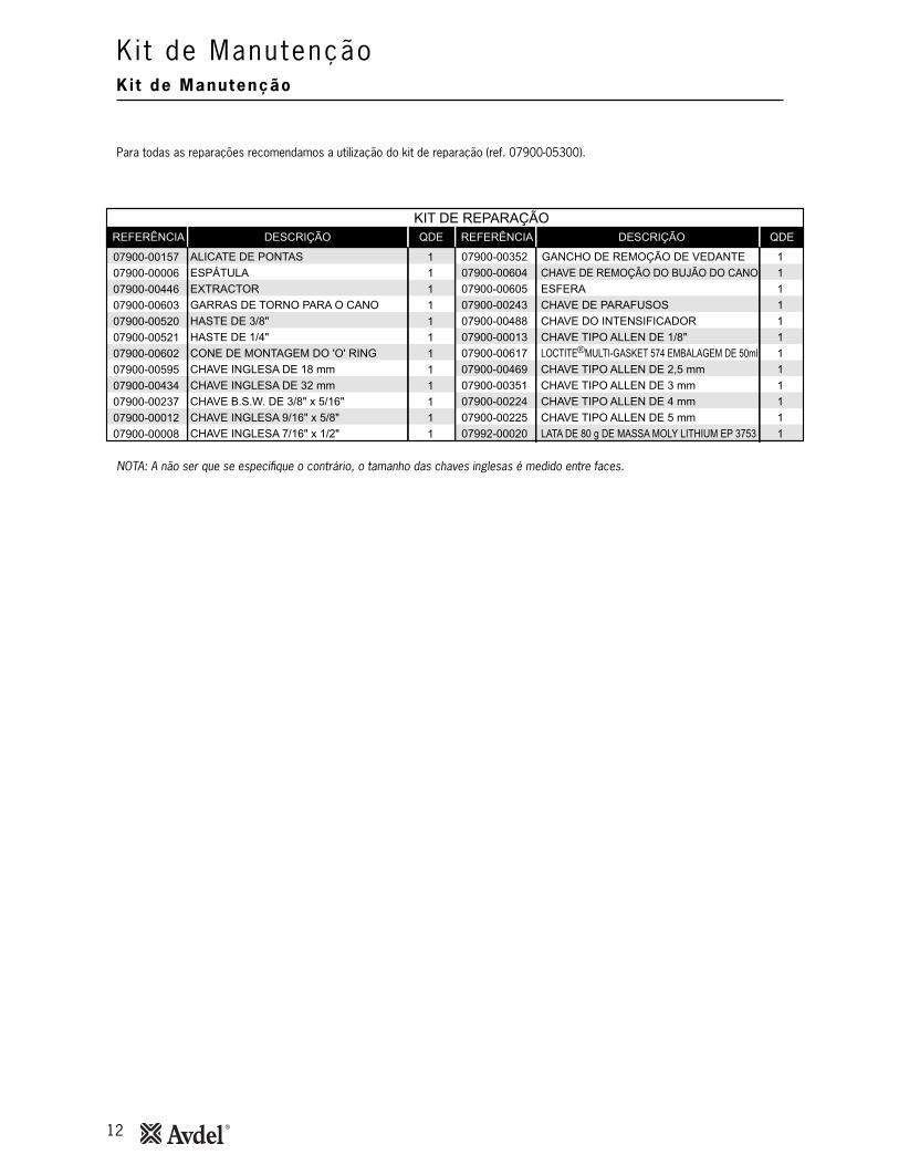
Para todas as reparações recomendamos a utilização do kit de reparação (ref. 07900-05300).
NOTA: A não ser que se especifique o contrário, o tamanho das chaves inglesas é medido entre faces.
REFERÊNCIA DESCRIÇÃO QDE
07900-00157 1
07900-00006 1
07900-00446 1
07900-00603 1
07900-00520 1
07900-00521 1
07900-00602 1
07900-00595 1
07900-00434 1
07900-00237 1
07900-00012 1
07900-00008 1
KIT DE REPARAÇÃOREFERÊNCIA DESCRIÇÃO QDE
07900-00352 1
07900-00604 1
07900-00605 1
07900-00243 1
07900-00488 1
07900-00013 1
07900-00617 1
07900-00469 1
07900-00351 1
07900-00224 1
07900-00225 1
07992-00020 1
ALICATE DE PONTAS
ESPÁTULA
EXTRACTOR
GARRAS DE TORNO PARA O CANO
HASTE DE 3/8"
HASTE DE 1/4"
CONE DE MONTAGEM DO 'O' RING
CHAVE INGLESA DE 18 mm
CHAVE INGLESA DE 32 mm
CHAVE B.S.W. DE 3/8" x 5/16"
CHAVE INGLESA 9/16" x 5/8"
CHAVE INGLESA 7/16" x 1/2"
GANCHO DE REMOÇÃO DE VEDANTE
CHAVE DE REMOÇÃO DO BUJÃO DO CANO
ESFERA
CHAVE DE PARAFUSOS
CHAVE DO INTENSIFICADOR
CHAVE TIPO ALLEN DE 1/8"
LOCTITE MULTI-GASKET 574 EMBALAGEM DE 50ml
CHAVE TIPO ALLEN DE 2,5 mm
CHAVE TIPO ALLEN DE 3 mm
CHAVE TIPO ALLEN DE 4 mm
CHAVE TIPO ALLEN DE 5 mm
LATA DE 80 g DE MASSA MOLY LITHIUM EP 3753
®

13
Conjunto da ferramenta de cursor pneumático, intensificador e caixa de controlo 07536-02100
4 5
9
2
6
3
7 8
1TUBO AZUL
TUBO PRETO
A A
CURSOR GARRASPOSTERIORES
SINAL
TUBOPRATEADO
TUBOVERDE
TUBOBRANCO
CORTE PARCIAL 'A-A'(PLACA DE PROTECCAO REMOVIDA)
~
74405-12080
14
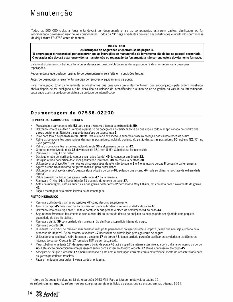
Manutenção
Todos os 500 000 ciclos a ferramenta deverá ser desmontada e, se os componentes estiverem gastos, danificados ou forrecomendado dever-se-ão usar novos componentes. Todos os “O” rings e vedantes deverão ser substituídos e lubrifcados com massadeMoly-Lithium EP 3753 antes de montar.
IMPORTANTEAs Instruções de Segurança encontram-se na página 4.
O empregador é responsável por assegurar que as instruções de manutenção da ferramenta são dadas ao pessoal apropriado. O operador não deverá estar envolvido na manutenção ou reparação da ferramenta a não ser que esteja devidamente formado.
Salvo instruções em contrário, a linha de ar deverá ser desconectada antes de se proceder à desmontagem ou a quaisquerreparações.
Recomenda-se que qualquer operação de desmontagem seja feita em condições limpas.
Antes de desmontar a ferramenta, precisa de remover o equipamento de ponta.
Para manutenção total da ferramenta aconselhamos que prossiga com a desmontagem dos subconjuntos pela ordem mostradaabaixo depois de ter desligado o tubo hidráulico da unidade do intensificador e a linha de ar do gatilho da válvula do intensificador,separando assim a unidade de pistola da unidade do intensificador.
CILINDRO DAS GARRAS POSTERIORES
• Manualmente carregue no clip 53 para cima e remova a tampa da extremidade 59.• Utilizando uma chave Allen *, remova o parafuso de cabeça oca 6 certificando-se de que expele todo o ar aprisionado no cilindro das
garras posteriores. Remova o segundo parafuso de cabeça oca 6.• Puxe para fora o bujão traseiro 50. Nota: Para auxiliar à extracção, a superfície traseira do bujão possui uma rosca de 5 mm.• Retire os componentes pneumáticos das garras posteriores, incluindo conjunto do pistão das garras posteriores 60, esbarro 52, 'O' ring
12 e garras 32.• Retire os componentes restantes, incluindo mola 36 e alojamento de garras 42.• O comprimento livre da mola 36 deverá ser de 38,1 mm (1,5"). Substitua se for necessário.• Remova o 'O' ring 11 do pistão.• Desligue o tubo concertina do cursor pneumático (verde) 49 do conector em ângulo 22.• Desligue o tubo concertina do cursor pneumático (prateado) 38 do cotovelo dentado 30.• Utilizando uma chave Allen*, remova os cinco parafusos de retenção do punho 3 e 4 e as quatro porcas 8 do punho da ferramenta.• Agarre o cano 44 num torno de garras macias* para evitar danos.• Utilizando uma chave de caixa*, desaparafuse o bujão do cano 46, evitando que o cano 44 rode ao utilizar uma chave de extremidade
aberta*.• Retire puxando o cilindro das garras posteriores 47 da ferramenta.• Remova o 'O' ring 14, a fita de fricção 41 e a mola de retorno do cano 37.• Antes da montagem, unte as superfícies das garras posteriores 32 com massa Moly Lithium, em contacto com o alojamento de garras
42.• Faça a montagem pela ordem inversa da desmontagem.
PISTÃO HIDRÁULICO
• Remova o cilindro das garras posteriores 47 como descrito anteriormente.• Agarre o corpo 45 num torno de garras macias* para evitar danos, retire o limitador de curso 40.• Utilizando uma chave tipo allen*, solte o parafuso 5 que prende o bloco de comutação 54 ao cano 44.• Segure com firmeza na ferramenta e puxe o cano 44 do corpo (de dentro do conjunto da cabeça pode ser ejectado uma pequena
quantidade de óleo hidráulico).• Remova o pistão 39 com cuidado de maneira a não danificar a superfície interna do corpo.• Remova o vedante 16.• O vedante 17 é difícil de remover sem danificar, mas pode permanecer no lugar durante a limpeza (desde que não seja afectado pelo
processo de limpeza). Se no entanto, o vedante 17 necessitar de substituição prossiga como se segue:• Utilizando uma espátula*, retire forçando o vedante 17 do corpo 45, tendo cuidado para não danificar as cavidades e os diâmetros
internos do corpo. O vedante 17 removido TEM de ser descartado.• Para substituir o vedante 17, desaparafuse o bujão de purga 43 até a superfície interna estar nivelada com o diâmetro interno do corpo
45. Esta acção proporcionará uma passagem suave para a inserção do novo vedante 17 através da traseira do corpo 45.• Assegure-se de que o vedante 17 é bem lubrificado e está com a orientação correcta com a extremidade aberta do vedante virada para
as garras posteriores traseiras.• Faça a montagem pela ordem inversa da desmontagem..
* refere-se às peças incluídas no kit de reparação 0753 MkII. Para a lista completa veja a página 12.As referências em negrito referem-se aos conjuntos gerais e às listas de peças que se encontram nas páginas 16-17.
D e s m o n t a g e m d a 0 7 5 3 6 - 0 2 2 0 0

15
D e s m o n t a g e m d a 0 7 5 3 6 - 0 2 2 0 0
Manutenção
I M P O R T A N T E
Verifique a ferramenta para reparação diária e semanal.A preparação é SEMPRE necessária depois de se ter desmontado a ferramenta e antes de a operar.
CONJUNTO DO GATILHO
• Para desmontar/reparar a ferramenta, remova as coberturas da ferramenta conforme foi descrito anteriormente.• Desligue todos os tubos de ar do conjunto, tendo cuidado para não os danificar. Remova o conjunto.• Utilizando uma chave inglesa*, desaperte o retentor 34 e remova-o. Tenha cuidado para guardar a mola 31.• Com a ajuda de uma alavanca remova o 'O' ring 10 tendo cuidado para não danificar o veio 35 e as bases do retentor 34.• Limpe e volte a montar utilizando um novo 'O' ring 10.• Verifique o comprimento da mola 50 que tem de ser 12,7 mm (0,5") de comprimento livre - substitua se for necessário.• Faça a montagem pela ordem inversa da desmontagem.
VÁLVULA DE LIGAR/DESLIGAR GARRAS POSTERIORES
• A unidade está concebida de maneira que seja requerido o mínimo de manutenção durante a vida da ferramenta.• Se for necessário desmontar a válvula, prossiga como se segue:• Retire o alojamento do disparo 56 conforme descrito na secção "Pistão hidráulico".• Utilizando uma chave de parafusos*, remova com cuidado a anilha recortada cromada 18 da bobina de ar das garras posteriores
55 e descarte a anilha.• Extraia a bobina de ar das garras posteriores 55 do bloco comutador 54.• Tendo cuidado para não danificar a bobina de ar das garras posteriores 55, remova os 'O' rings 12.• Limpe a bobina e volte a montar os 'O' rings novos 12 utilizando o cone de montagem* e insira no bloco comutador 54 prestando
atenção à orientação.• Monte uma nova anilha recortada cromada 18 apertando num torno com maxilas macias para evitar danos. NÃO UTILIZE FORÇA
DESNECESSÁRIA.• Termine a montagem pela ordem inversa da desmontagem.
PUNHO E TAMPA DA EXTREMIDADE
• Limpe e inspeccione as peças moldadas quanto a fendas ou outros danos.
CURSOR
• Limpe e lubrifique ocasionalmente o conjunto do cursor com um pouco de óleo fino.
* Refere-se às peças incluídas no kit de reparação 0753 MkII. Para a lista completa veja a página 12.As referências em negrito referem-se aos conjuntos gerais e às listas de peças que se encontram nas páginas 16-17.
16
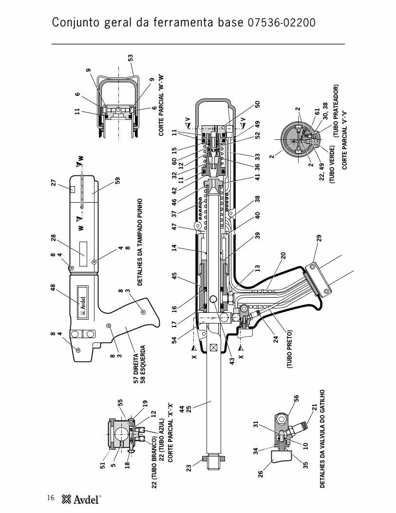
Conjunto geral da ferramenta base 07536-02200
8 48 4
4 88 3
8 3
48
DET
ALH
ES D
A TA
MPA
DO
PU
NH
O
WW
1444 25
23
1754
4637
3242
1211
11
V V
1516
4547
60
3941
3349
36
2
(TU
BO
VER
DE)
(TU
BO
PR
ATEA
DO
R)
5238
40
29
2024
CO
RTE
PAR
CIA
L 'W
'-'W
'
CO
RTE
PAR
CIA
L 'V
'-'V'
6
9
69
53
X X
DET
ALH
ES D
A VA
LVU
LA D
O G
ATIL
HO
35
26
21
3431
5610
5013
2827 59
57 D
IREI
TA58
ESQ
UER
DA
43
11
551 18
CO
RTE
PAR
CIA
L 'X
'-'X
'55 1912
22 (T
UB
O A
ZUL)
22 (T
UB
O B
RAN
CO
)
(TU
BO
PR
ETO
)
WW
6130
, 38
22, 4
92
2
17
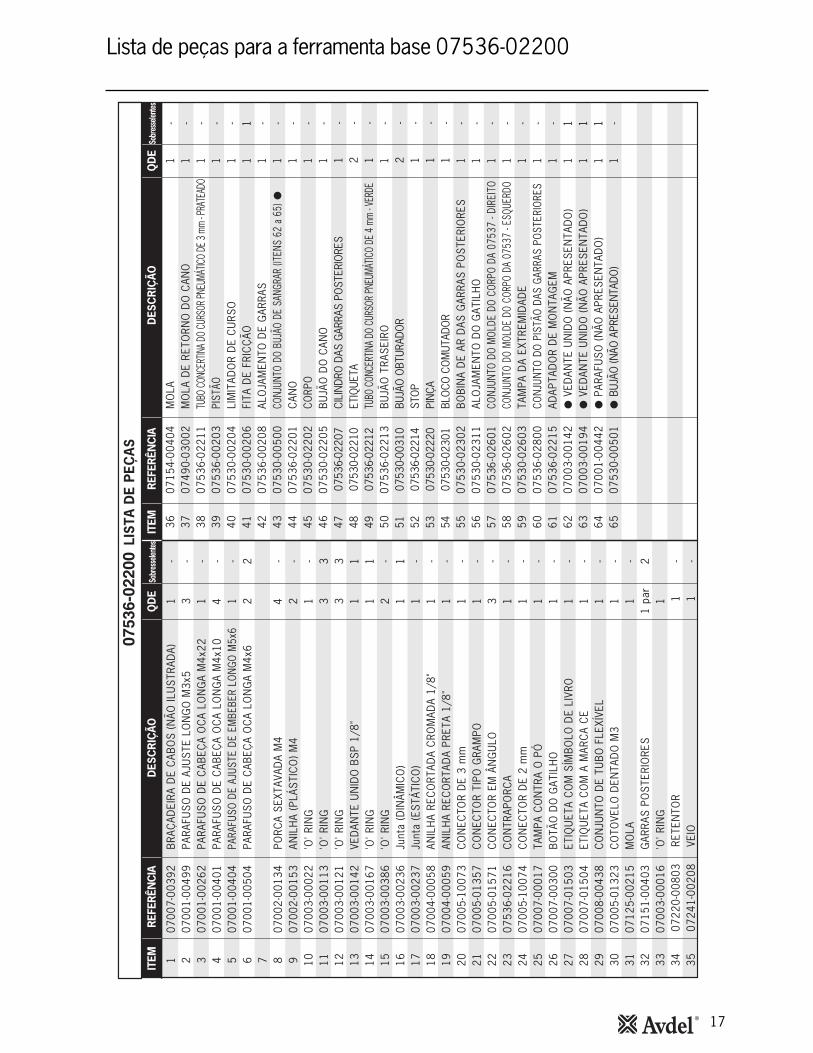
Lista de peças para a ferramenta base 07536-02200
0753
6-02
200
18
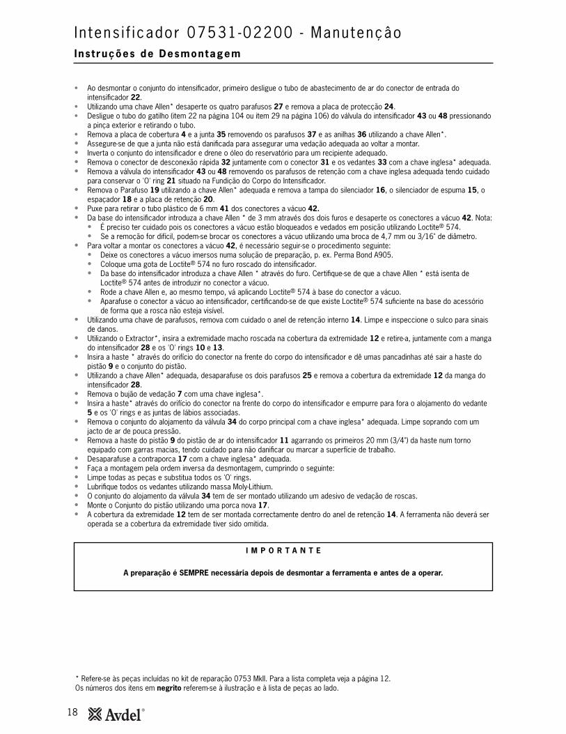
Ins t ruções de Desmontagem
I n tens i f i cador 07531-02200 - Manutençâo
• Ao desmontar o conjunto do intensificador, primeiro desligue o tubo de abastecimento de ar do conector de entrada dointensificador 22.
• Utilizando uma chave Allen* desaperte os quatro parafusos 27 e remova a placa de protecção 24.• Desligue o tubo do gatilho (item 22 na página 104 ou item 29 na página 106) do válvula do intensificador 43 ou 48 pressionando
a pinça exterior e retirando o tubo.• Remova a placa de cobertura 4 e a junta 35 removendo os parafusos 37 e as anilhas 36 utilizando a chave Allen*.• Assegure-se de que a junta não está danificada para assegurar uma vedação adequada ao voltar a montar.• Inverta o conjunto do intensificador e drene o óleo do reservatório para um recipiente adequado.• Remova o conector de desconexão rápida 32 juntamente com o conector 31 e os vedantes 33 com a chave inglesa* adequada.• Remova a válvula do intensificador 43 ou 48 removendo os parafusos de retenção com a chave inglesa adequada tendo cuidado
para conservar o 'O' ring 21 situado na Fundição do Corpo do Intensificador.• Remova o Parafuso 19 utilizando a chave Allen* adequada e remova a tampa do silenciador 16, o silenciador de espuma 15, o
espaçador 18 e a placa de retenção 20.• Puxe para retirar o tubo plástico de 6 mm 41 dos conectores a vácuo 42.• Da base do intensificador introduza a chave Allen * de 3 mm através dos dois furos e desaperte os conectores a vácuo 42. Nota:
• É preciso ter cuidado pois os conectores a vácuo estão bloqueados e vedados em posição utilizando Loctite® 574.• Se a remoção for difícil, podem-se brocar os conectores a vácuo utilizando uma broca de 4,7 mm ou 3/16" de diâmetro.
• Para voltar a montar os conectores a vácuo 42, é necessário seguir-se o procedimento seguinte:• Deixe os conectores a vácuo imersos numa solução de preparação, p. ex. Perma Bond A905.• Coloque uma gota de Loctite® 574 no furo roscado do intensificador.• Da base do intensificador introduza a chave Allen * através do furo. Certifique-se de que a chave Allen * está isenta de
Loctite® 574 antes de introduzir no conector a vácuo.• Rode a chave Allen e, ao mesmo tempo, vá aplicando Loctite® 574 à base do conector a vácuo.• Aparafuse o conector a vácuo ao intensificador, certificando-se de que existe Loctite® 574 suficiente na base do acessório
de forma que a rosca não esteja visível.• Utilizando uma chave de parafusos, remova com cuidado o anel de retenção interno 14. Limpe e inspeccione o sulco para sinais
de danos.• Utilizando o Extractor*, insira a extremidade macho roscada na cobertura da extremidade 12 e retire-a, juntamente com a manga
do intensificador 28 e os 'O' rings 10 e 13.• Insira a haste * através do orifício do conector na frente do corpo do intensificador e dê umas pancadinhas até sair a haste do
pistão 9 e o conjunto do pistão.• Utilizando a chave Allen* adequada, desaparafuse os dois parafusos 25 e remova a cobertura da extremidade 12 da manga do
intensificador 28.• Remova o bujão de vedação 7 com uma chave inglesa*.• Insira a haste* através do orifício do conector na frente do corpo do intensificador e empurre para fora o alojamento do vedante
5 e os 'O' rings e as juntas de lábios associadas.• Remova o conjunto do alojamento da válvula 34 do corpo principal com a chave inglesa* adequada. Limpe soprando com um
jacto de ar de pouca pressão.• Remova a haste do pistão 9 do pistão de ar do intensificador 11 agarrando os primeiros 20 mm (3/4") da haste num torno
equipado com garras macias, tendo cuidado para não danificar ou marcar a superfície de trabalho.• Desaparafuse a contraporca 17 com a chave inglesa* adequada.• Faça a montagem pela ordem inversa da desmontagem, cumprindo o seguinte:• Limpe todas as peças e substitua todos os 'O' rings.• Lubrifique todos os vedantes utilizando massa Moly-Lithium.• O conjunto do alojamento da válvula 34 tem de ser montado utilizando um adesivo de vedação de roscas.• Monte o Conjunto do pistão utilizando uma porca nova 17.• A cobertura da extremidade 12 tem de ser montada correctamente dentro do anel de retenção 14. A ferramenta não deverá ser
operada se a cobertura da extremidade tiver sido omitida.
* Refere-se às peças incluídas no kit de reparação 0753 MkII. Para a lista completa veja a página 12.Os números dos itens em negrito referem-se à ilustração e à lista de peças ao lado.
I M P O R T A N T E
A preparação é SEMPRE necessária depois de desmontar a ferramenta e antes de a operar.

19
I n tens i f i cador 07531-02200
31
33
34
6
30
35
36
1 23
45 7
89 11
1213
1415
16
17
19
18
20
21
37
39
41
42
22
232427
32
2829
10
38
43
2526
54
'B'
'A'
6
484645
53 52 51
47
49
50
44
40
*
*
*
NotaAlgumas unidades não incluem estes itens (A ligação necessária obtém-se através de abertura interna)
VISTA A ILUSTRAR A VÁLVULA COMPAIRVISTA NA SETA 'A'
VISTA NA SETA 'B'
VISTA A ILUSTRAR A VÁLVULA FESTO
LISTA DE PEÇAS 07531-02200
1 07003-00037 1 1 2 07240-00211 1 - 3 07001-00418 1 1 4 07240-00210 1 - 5 71420-02006 1 - 6 07003-00153 2 - 7 71420-02007 1 - 8 71420-02300 1 - 9 71420-02008 1 - 10 07003-00182 1 1 11 07531-00202 1 - 12 07531-00204 1 - 13 07003-00183 1 1 14 07004-00069 1 1 15 07240-00213 1 1 16 07240-00214 1 - 17 07002-00017 1 1 18 07240-00215 1 - 19 07001-00417 1 1 20 07240-00216 1 - 21 07003-00042 1 1 22 07005-00041 1 - 23 07003-00065 1 - 24 07240-00220 1 - 25 07001-00375 2 - 26 07003-00238 1 1 27 07001-00396 4 -
28 07531-00201 1 - 29 07003-00337 1 1 30 07003-00336 2 2 31 07005-00406 1 - 32 07005-00759 1 - 33 07003-00142 2 1 34 07240-00400 1 - 35 07240-00209 1 1 36 07002-00073 4 1 37 07001-00554 4 1 38 07007-01504 1 - 39 07240-00217 1 - 40 07531-00205 2 - 41 07005-00596 - - 42 07245-00103 2 - 43 07005-00590 1 1 44 07005-01431 1 1 45 07005-00668 1 - 46 07005-00670 1 - 47 07005-01084 - - 48 07005-01524 1 - 49 07001-00176 3 - 50 07007-00292 1 - 51 07005-00647 1 - 52 07005-01085 - - 53 07005-00855 1 - 54 07007-01503 1 -
VEDANTEPARAFUSO DE ENCHIMENTOPARAFUSO DE SANGRARPLACA DE COBERTURAALOJAMENTO DO VEDANTE'O' RINGBUJÃO DE VEDAÇÃOCONJUNTO DO CORPOHASTE DO PISTÃO'O' RINGPISTÃO DE ARCOBERTURA DA EXTREMIDADE'O' RINGANEL DE RETENÇÃO SILENCIADOR DE ESPUMATAMPA DO SILENCIADORPORCAESPAÇADORPARAFUSOPLACA DE RETENÇÃO'O' RINGCONECTORANILHAPLACA DE PROTECÇÃOPARAFUSO'O' RINGPARAFUSO
MANGAJUNTA DE LÁBIOSJUNTA DE LÁBIOSCONECTORCONECTOR DE DESCONEXÃO RÁPIDAVEDANTE CONJUNTO DO ALOJAMENTO DA VÁLVULA
JUNTAANILHAPARAFUSOETIQUETAETIQUETAETIQUETA* TUBO PLÁSTICO DE 6 mm* CONECTOR A VAZIO VÁLVULA COMPAIRCONECTOR DA ANTEPARABUJÃO M5ANEL DE VEDAÇÃO M5TUBO PLÁSTICO DE 4 mm (150 mm)VÁLVULA FESTOPARAFUSOTAMPA CONTRA O PÓ REDCAP BSP 1/4"
CONECTORTUBO DE PLÁSTICO DE 6 mm (150 mm)UNIÃO DA ANTEPARAETIQUETA
ITEM REFERÊNCIA DESCRIÇÃO QDE ITEM REFERÊNCIA DESCRIÇÃO QDESOBRESSE-LENTES
SOBRESSE-LENTES

20
Pormenores do ó leo
Proced imento d e P r e p a r a ç ã o
D a d o s d e S e g u r a n ç a Ó l e o H y s p i n ® V G 3 2 e A W S 3 2
Preparação
A preparação é SEMPRE necessária depois de se ter desmontado a ferramenta e antes de a operar. Poderá também ser necessáriorestaurar o curso completo após uso considerável, quando o curso puder ser reduzido e os rebites não estiverem completamentecolocados por uma operação do gatilho.
I M P O R T A N T E
NÃO OPERAR O GATILHO ENQUANTO O PARAFUSO DE SANGRAR ESTIVER REMOVIDO.Todas as operações devem ser efectuadas sobre uma bancada limpa, com mãos limpas numa área limpa.
Certifique-se de que o óleo novo está completamente limpo e isento de bolhas de ar.Deve-se ter SEMPRE cuidado para garantir que matéria estranha não entra na ferramenta, ou poderá resultar
em danos graves.
Os números de item em negrito referem-se aos conjuntos gerais e às listas de peças nas páginas 16-19.
• Remova o parafuso 2 e o vedante 1 da placa de cobertura de plástico 4 no reservatório do intensificador.• Deite o óleo de preparação no reservatório até se encontrar a aproximadamente 12 mm (1/2") do topo.• Volte a montar o parafuso 2 e o vedante 1.• Ligue a unidade do intensificador ao abastecimento de ar. Remova o parafuso do reservatório.• Com a unidade de pistola 07536 montada na unidade intensificadora e mantida abaixo do nível da unidade intensificadora,
desaparafuse duas voltas o parafuso de purga 64 do conjunto do bujão de purga 43 da ferramenta 07536 e deixe sair o óleo daferramenta.
• Quando o óleo sair livremente e sem bolhas de ar, aperte o parafuso de sangrar.• Encha o reservatório da unidade do intensificador com óleo de preparação.• Opere a ferramenta até que quaisquer bolhas de ar presentes no óleo sejam expelidas no reservatório de óleo.
O óleo recomendado para escorva é Hyspin® VG32 e AWS 32, disponível em recipientes de 0,5 litros (referência 07992-00002) oude um galão (referência 07992-00006). Consulte os dados de segurança abaixo.
Primeiros socorrosPELE:Lave muito bem com água e sabão o mais depressa possível. Contacto ocasional não requer atenção imediata. Contacto temporário nãorequer atenção imediata. INGESTÃO: Consulte imediatamente o médico. NÃO provoque vómitos.OLHOS:Irrigue imediatamente com água durante vários minutos. Embora NÃO seja um irritante primário, após contacto poderá ocorrer um ligeirairritação.
IncêndioMeios de extinção adequados: CO2, pó seco, espuma ou neblina de água. NÃO use jactos de água.
Ambiental
DESCARTE: Através de um contratante autorizado para um local aprovado. Pode ser incinerado. Produto utilizado pode ser enviado para
recuperação.
DERRAMAMENTO: Evite a entrada para esgotos, fossas e cursos de água. Limpe com material absorvente.
ManuseamentoUse protecção de olhos, luvas impermeáveis (p.ex. de PVC) e um avental de plástico. Utilize em áreas bem ventiladas.
ArmazenamentoNão são necessárias precauções especiais.

21
Reso lução De Prob lemas
Outros sintomas ou falhas devem ser comunicados ao seu distribuidor local Avdel® ou centro de reparação autorizados.
Sintoma Poss íve l Causa Solução Ref . de Pãg.
A ferramenta não coloca
o elemento de fixação
'Deslize de mandril' - as
garras não agarram o
mandril
As garras não libertam
o mandril
Os elementos de fixação
não estão a ser
alimentados através das
garras de ponta
Desgaste excessivo das
garras posteriores
A alimentar de mais de
um elemento de fixação
de cada vez
Aumente a pressão de ar
Lubrifique a ferramenta no ponto de entrada
Verifique o aperto do elemento de fixação e
o tamanho do furo da aplicação
Ligue as garras de ponta
Veja “Procedimento de Preparação”
Limpe ou substitua conforme for necessário
Aumente a pressão de ar/volume
Substitua o comutador
Substitua os 'O' rings do pistão 8.
Substitua o mandril
Contacte o pessoal da Avdel
Limpe e lubrifique
Substitua os 'O' rings
Verifique os tubos pneumáticos
Contacte o pessoal da Avdel
Ligue as garras posteriores
Substitua as garras posteriores
Volte a montar assegurando orientação
correcta
Monte o cursor correctamente
Monte garras de ponta correctas
Monte mola seguidora de mandril correcta
Monte o seguidor de mandril correcto
Ajuste a folga para 1,5 mm - 3 mm. Veja
'Para Carregar a Ferramenta'
Limpe e unte com óleo o cursor
Substitua o cursor
Monte mola seguidora de mandril correcta
Substitua a mola de retorno do cano
Verifique o tamanho do furo da aplicação, a
espessura e a capacidade de agarração do
elemento de fixação
Verifique como para 'Deslize de Mandril',
fase 2
Ajuste a folga para 1,5 mm - 3 mm (1/16" -
1/8"). Veja 'Para Carregar a Ferramenta'.
Pressão de ar baixa
Falta de lubrificação
Carga alargadora alta
Verifique para tamanho correcto de mandril
Garras posteriores desligadas
Ar no sistema hidráulico
Garras posteriores gastas ou sujas
Volume/pressão insuficiente
Comutador de garras posteriores não
operacional
Fugas de ar para as garras posteriores
Mandril partido e não alcança as garras
posteriores
Falha na caixa de controlo pneumático
Garras posteriores ou alojamento de garras sujo
Interruptor das garras posteriores avariado
Sinal de ar aprisionado
Falha na caixa de controlo pneumático
Garras posteriores não ligadas
Garras posteriores gastas
Orientação do cursor incorrecta
Cursor incorrecto
Garras de ponta incorrectas
Mola seguidora de mandril não montada
Comprimento do seguidor de mandril
Folga incorrecta entre a cabeça do elemento de
fixação e as garras de ponta, quando carregada
Cursor pneumático gasto
Mola exterior frouxa à volta do cursor
Mola seguidora de mandril montada é
incorrecta
Mola de retorno do cano gasta ou partida
Carga alargadora alta
Deslize de mandril
Folga incorrecta entre a cabeça do elemento
de fixação e as garras de ponta, quando
carregada
20
9-10
9-10

22
Notas

Data de Emissão
A. Seewraj - Gestor de Engenharia de Produtos - Ferramentas Automatizadas
Este estojo contém uma ferramenta eléctrica que está emconformidade com a Directiva Máquinas 2006/42/EC. A'Declaração de Conformidade' está incluída.
Dec laração de Conformidade
Nós, a Avdel UK Limited; Watchmead Industrial Estate, Welwyn Garden City, Hertfordshire, AL7 1LY
declaramos sob a nossa única e inteira responsabilidade que o produto:
Modelo 7336
Nº de série da ferramenta manual
Nº de série do intensificador ....................................
A que se refere a presente declaração está em conformidade com as seguintes normas:
EN ISO 12100 - partes 1 e 2
BS EN ISO 8662 - parte 6 BS EN ISO 11202
BS EN ISO 3744 BS EN 982
ISO EN 792 - parte 13-2000 BS EN 983
Seguindo as disposições da Directiva Máquinas 2006/42/EC.
23
Since 1 936 2010 Since 1922
www.avdel-global.comwww.infastech.com
02.2
011
• ©
201
0 In
fast
ech
Autosert® (equipment), Avbolt ®, Avdel®, Avdelmate®, Avdel TX2000®, Avdelok®, Avex®, Avibulb®, Avinox®, Avinut™, Avlug®, Avmatic®, Avplas®,Avseal®, Avsert®, Avtainer®, Avtronic®, Briv®, Bulbex®, Chobert®, Eurosert®, Fastriv®, Finsert®, Genesis®, Grovit®, Hemlok®, Hexsert®, Holding your world together®, Hydra®, Interlock®, Klamp-Tite ®, Klamptite KTR ®, Kvex®, Maxlok®, Monobolt®, Monobulb ®, Neobolt®, Nutsert®, Nutsert SQ®, Portariv®, Rivmatic®, Rivscrew®, Speed Fastening®, Squaresert®, Stavex®, Supersert®, Thin Sheet Nutsert®, Titan®, T-Lok®, TLR®, TSN®, TX2000®, Versa-Nut®, Viking® e Viking 360 ® são marcas comerciais da Avdel UK Limited. Infastech™ e Our Technology, Your Success™ são marcas comerciais da Infastech Intellectual Properties Pte Ltd. Os nomes e logótipos de outras empresas mencionadas neste documento podem ser marcas comerciais dos seus respectivos proprietários. Este documento tem objectivos meramente informativos. A Infastech não oferece quaisquer garantias, explícitas ou implícitas, neste documento. Os dados apresentados estão sujeitos a alterações sem aviso prévio em virtude do desenvolvimento contínuo do produto e do melhoramento da política. O seu representante local Avdel está à sua disposição caso precise de confirmar esta última informação.
AUSTRÁLIAInfastech (Australia) Pty Ltd.891 Wellington RoadRowvilleVictoria 3178Tel: +61 3 9765 6400Fax: +61 3 9765 [email protected]
CANADÁAvdel Canada Limited1030 Lorimar DriveMississaugaOntario L5S 1R8Tel: +1 905 364 0664Fax: +1 905 364 [email protected]
CHINAInfastech (China) Ltd.RM 1708, 17/F., Nanyang Plaza,57 Hung To Rd., Kwun TongHong KongTel: +852 2950 0631Fax: +852 2950 [email protected]
FRANÇAAvdel France S.A.S.33 bis, rue des ArdennesBP4 75921 Paris Cedex 19Tel: +33 (0) 1 4040 8000Fax: +33 (0) 1 4208 [email protected]
ALEMANHAAvdel Deutschland GmbHKlusriede 2430851 LangenhagenTel: +49 (0) 511 7288 0Fax: +49 (0) 511 7288 [email protected]
ÍNDIAInfastech Fastening Technologies India Private LimitedPlot No OZ-14, Hi Tech SEZ,SIPCOT Industrial Growth Center,Oragadam, Sriperumbudur Taluk, Kanchipuram District,602105 TamilnaduTel: +91 44 4711 8001Fax: +91 44 4711 [email protected]
ITÁLIAAvdel Italia S.r.l.Viale Lombardia 51/5320047 Brugherio (MI)Tel: +39 039 289911Fax: +39 039 [email protected]
JAPÃOInfastech Kabushiki KaishaCenter Minami SKY, 3-1 Chigasaki-Chuo, Tsuzuki-ku,Yokohama-city, Kanagawa PrefectureJapan 224-0032Tel: +81 45 947 1200Fax: +81 45 947 [email protected]
MALÁSIAInfastech (Malaysia) Sdn BhdLot 63, Persiaran Bunga Tanjung 1,Senawang Industrial Park70400 SerembanNegeri SembilanTel: +606 676 7168Fax: +606 676 [email protected]
SINGAPURAInfastech (Singapore) Pte Ltd. 31 Kaki Bukit Road 3#05-03/06 TechlinkSingapore, 417818Tel: +65 6372 5653Fax: +65 6744 [email protected]
REPÚBLICA DA COREIAInfastech (Korea) Ltd.212-4, Suyang-Ri,Silchon-Eup, Kwangju-City,Kyunggi-Do, Korea, 464-874Tel: +82 31 798 6340Fax: +82 31 798 [email protected]
ESPANHAAvdel Spain S.A.C/ Puerto de la Morcuera, 14Poligono Industrial Prado OveraCtra. de Toledo, km 7,828919 Leganés (Madrid)Tel: +34 91 3416767Fax: +34 91 [email protected]
TAIWANInfastech/Tri-Star LimitedNo 269-7, Baodong Rd, Guanmiao Township,71841 Tainan County,Taiwan, R.O.CTel: +886 6 596 5798 (ext 201)Fax: +886 6 596 [email protected]
REINO UNIDOAvdel UK LimitedPacific House2 SwiftfieldsWatchmead Industrial EstateWelwyn Garden CityHertfordshire AL7 1LYTel: +44 (0) 1707 292000Fax: +44 (0) 1707 [email protected]
EUAAvdel USA LLC614 NC Highway 200 SouthStanfield, North Carolina 28163Tel: +1 704 888 7100Fax: +1 704 888 [email protected]
Manual No. Issue Change Note No. Date
B2 07/103 MAR 07
B3 07/261 OCT 07
B4 08/142
B5 11/082
07900-00846
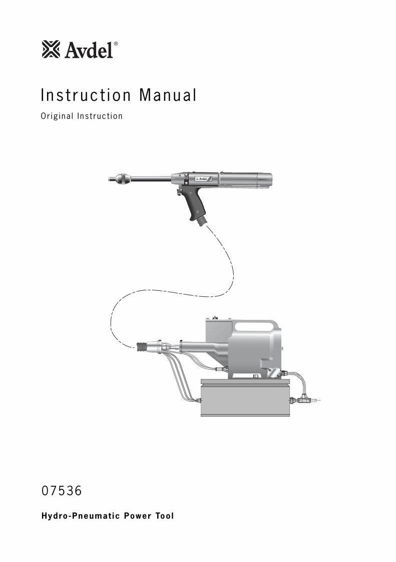
Hydro-Pneumat ic Power Too l
07536
0753
TYPE
I n s t ruc t i on Manua lOr ig i na l I ns t ruc t i on

3
Safety Rules 4
SpecificationsSpecification for 07536 Tool 5Specification for 07531 Intensifier 5
Intent of Use 6Tool Dimensions - 07536 Model 6
Putting into ServiceAir Supply 7Air Cursors 8Loading and Re-loading the Tool 9-10Operating Procedure 10
Servicing the ToolPneumatic Control Box 11Daily 11 Weekly 11Moly Lithium Grease EP 3735 Safety Data 11Service Kit 12
MaintenanceAir Cursor Tool, Intensifier & Control Box Assembly 1307536-02100 and Parts ListDismantling 07536-02200 14-15General Assembly of Base Tool 07536-02200 16Parts List for Base Tool 07536-02200 17Intensifier 07531-02200 - Maintenance 18Dismantling Instructions 18Intensifier 07531-02200 - General Assembly and 19Parts List
PrimingOil Details 20Hyspin® VG32 and AWS 32 Oil Safety Data 20Priming Procedure 20
Fault DiagnosisSymptom, Possible Cause and Remedy 21
LIMITED WARRANTY
Avdel makes the limited warranty that its products will be free of defects in workmanship and materials
which occur under normal operating conditions. This Limited Warranty is contingent upon: (1) the product
being installed, maintained and operated in accordance with product literature and instructions, and (2)
confirmation by Avdel of such defect, upon inspection and testing. Avdel makes the foregoing limited
warranty for a period of twelve (12) months following Avdel’s delivery of the product to the direct purchaser
from Avdel. In the event of any breach of the foregoing warranty, the sole remedy shall be to return the
defective Goods for replacement or refund for the purchase price at Avdel’s option. THE FOREGOING
EXPRESS LIMITED WARRANTY AND REMEDY ARE EXCLUSIVE AND ARE IN LIEU OF ALL OTHER WARRANTIES
AND REMEDIES. ANY IMPLIED WARRANTY AS TO QUALITY, FITNESS FOR PURPOSE, OR MERCHANTABILITY
ARE HEREBY SPECIFICALLY DISCLAIMED AND EXCLUDED BY AVDEL.
Avdel UK Limited policy is one of continuous product development and improvement and we reserve the right to change the specification of any product without prior notice.

4
1 Do not use outside the design intent.
2 The Hand Tool and Intensifier have been tested as separate items and combined. They must only be used together and under no
circumstances for any other purposes.
3 Do not use equipment with this tool/machine other than that recommended and supplied by Avdel UK Limited.
4 Any modification undertaken by the customer to the tool/machine, nose assemblies, accessories or any equipment supplied by Avdel
UK Limited. or their representatives, shall be the customer’s entire responsibility. Avdel UK Limited. will be pleased to advise upon any
proposed modification.
5 The tool/machine must be maintained in a safe working condition at all times and examined at regular intervals for damage and
function by trained competent personnel. Any dismantling procedure shall be undertaken only by personnel trained in Avdel UK
Limited. procedures. Do not dismantle this tool/machine without prior reference to the maintenance instructions. Please contact Avdel
UK Limited. with your training requirements.
6 The tool/machine shall at all times be operated in accordance with relevant Health and Safety legislation. In the U.K. the “Health and
Safety at Work Act 1974” applies. Any question regarding the correct operation of the tool/machine and operator safety should be
directed to Avdel UK Limited.
7 The precautions to be observed when using this tool/machine must be explained by the customer to all operators.
8 Always disconnect the airline from the tool/machine inlet before attempting to adjust, fit or remove a nose assembly.
9 Do not operate a tool/machine that is directed towards any person(s) or the operator.
10 Always adopt a firm footing or a stable position before operating the tool/machine.
11 Ensure that vent holes do not become blocked or covered and that hoses are always in good condition.
12 The operating pressure shall not exceed 7 bar (100 lbf/in2).
13 The combination of fastener, mandrel, hole size and sheet thickness shall be in accordance with Avdel UK Limited. Specifications.
14 Do not operate the tool if it is not fitted with a complete nose assembly unless specifically instructed otherwise.
15 When using the tool, the wearing of safety glasses is required both by the operator and others in the vicinity to protect against
fastener ejection, should a fastener be placed ‘in air’. We recommend wearing gloves if there are sharp edges or corners on the
application.
16 Take care to avoid entanglement of loose clothes, ties, long hair, cleaning rags etc. in the moving parts of the tool which should be
kept dry and clean for best possible grip.
17 When carrying the tool from place to place keep hands away from the trigger/lever to avoid inadvertent startup.
18 Excessive contact with hydraulic oil should be avoided. To minimize the possibility of rashes, care should be taken to wash
thoroughly.
I M P O R T A N TWhile a small amount of wear and marking will naturally occur through normal and correct use of mandrels, theymust be regularly examined for excessive wear and marking, with particular attention to the head diameter, thetail jaw gripping area of the shank or heavy pitting of the shank and any mandrel distortion. Mandrels which failduring use could forcibly exit the tool. It is the customer's responsibility to ensure that mandrels are replaced
before any excessive levels or wear and always before the maximum recommended number of placings. Contactyour Avdel. representative who will let you know what that figure is by measuring the broach load of your
application with a calibrated test tool. These tools can also be purchased under Part Number 07900-09080,supplied with all necessary information for testing in this manual.
Safe ty Ru les

Speci f icat ion for 07536 Too l
5
Air Pressure Minimum - Maximum 5-7 bar (70-100 lbf/in2)
Free Air Volume Required @ 5.1 bar /75 lbf/in2 2.6 litres (0.09 ft3)
Stroke Minimum 25 mm (1 in)
Pull Force @ 5.5 bar /80 lbf/in2 3.89 kN (875 lbf)
Cycle time Approximately 1 second
Noise Level Less than 70 dB(A)
Weight Pistol 1.2 kg (2.64 lb)
Vibration Less than 2.5 m/s2 (8 ft/s2)
Spec i f i ca t ions
Speci f icat ion for 07531 In tens i f ier
Air Pressure Minimum - Maximum 5-7 bar (70-100 lbf/in2)
Intensification Ratio 32:1
6
The pneumatic 07536 tool is a hand held light weight tool designed to place 1/16” Avlug® making it ideal for batch or flow-lineassembly in a wide variety of applications throughout all industries.
The Hand Tool and Intensifier have been tested as separate items and combined. They must only be used together and for no otherpurposes. Refer to "Putting into Service" on page 7 and 8 for connection details.
Part numbers are shown to order a complete tool but no nose equipment.
The tool number for the 07536 model is 07536-02200.See the general assemblies on pages 13-19.
Tool D imens ions - 07536 Model
I n ten t o f Use
0753
602.36
281.10
983.85
1305.12
47518.70 338
13.30
512
1636.41
1405.51
542.12
2017.91
42016.54
33
313
.10
50219.76
Part Number 07536-02100
7
86
42
0
10121416
TAKE OFF POINTFROM MAIN SUPPLY
STOP COCK(USED DURING MAINTENANCE
OF FILTER/REGULATOR OR LUBRICATION UNITS)
MAIN SUPPLYDRAIN POINT
PRESSURE REGULATORAND FILTER
(DRAIN DAILY)
3
METRES MAXIMUM
AIR LUBRICATIONPERMISSABLE
0753
TYPE
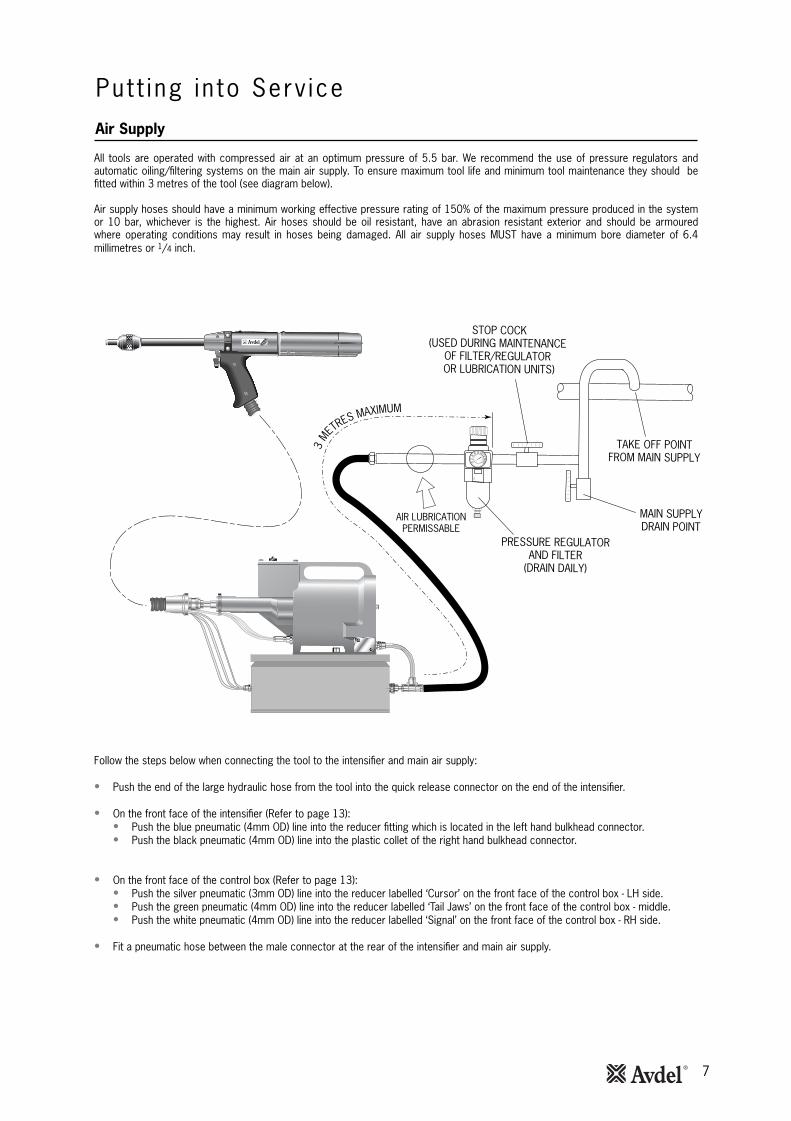
All tools are operated with compressed air at an optimum pressure of 5.5 bar. We recommend the use of pressure regulators andautomatic oiling/filtering systems on the main air supply. To ensure maximum tool life and minimum tool maintenance they should befitted within 3 metres of the tool (see diagram below).
Air supply hoses should have a minimum working effective pressure rating of 150% of the maximum pressure produced in the systemor 10 bar, whichever is the highest. Air hoses should be oil resistant, have an abrasion resistant exterior and should be armouredwhere operating conditions may result in hoses being damaged. All air supply hoses MUST have a minimum bore diameter of 6.4millimetres or 1/4 inch.
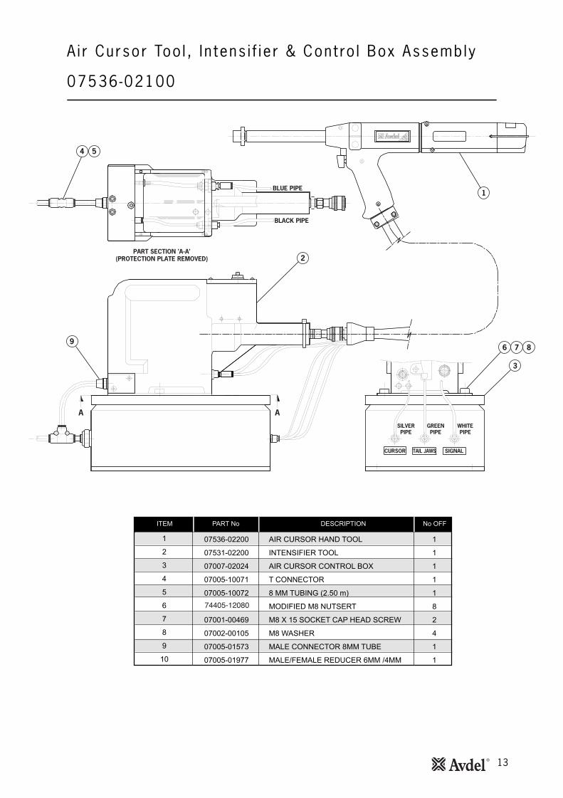
Follow the steps below when connecting the tool to the intensifier and main air supply:
• Push the end of the large hydraulic hose from the tool into the quick release connector on the end of the intensifier.
• On the front face of the intensifier (Refer to page 13):• Push the blue pneumatic (4mm OD) line into the reducer fitting which is located in the left hand bulkhead connector. • Push the black pneumatic (4mm OD) line into the plastic collet of the right hand bulkhead connector.
• On the front face of the control box (Refer to page 13): • Push the silver pneumatic (3mm OD) line into the reducer labelled ‘Cursor’ on the front face of the control box - LH side. • Push the green pneumatic (4mm OD) line into the reducer labelled ‘Tail Jaws’ on the front face of the control box - middle.• Push the white pneumatic (4mm OD) line into the reducer labelled ‘Signal’ on the front face of the control box - RH side.
• Fit a pneumatic hose between the male connector at the rear of the intensifier and main air supply.
Pu t t i ng in to Serv iceAir Supply
8
Air Cursors
Put t ing in to Serv ice
0753
TYPE
TOOL BARREL
CURSOR
NOSE JAWS
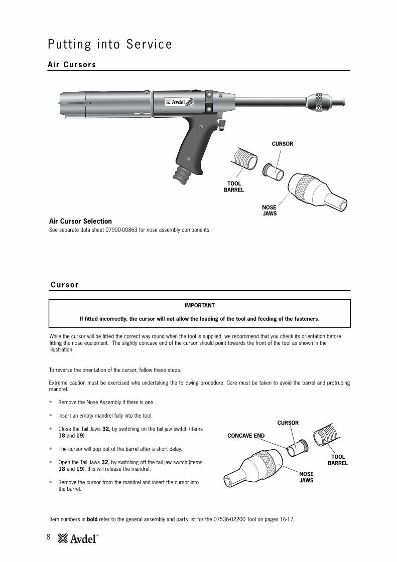
Air Cursor Selection
While the cursor will be fitted the correct way round when the tool is supplied, we recommend that you check its orientation beforefitting the nose equipment. The slightly concave end of the cursor should point towards the front of the tool as shown in theillustration.
To reverse the orientation of the cursor, follow these steps:
Extreme caution must be exercised whe undertaking the following procedure. Care must be taken to avoid the barrel and protrudingmandrel.
• Remove the Nose Assembly if there is one.
• Insert an empty mandrel fully into the tool.
• Close the Tail Jaws 32, by switching on the tail jaw switch (items18 and 19).
• The cursor will pop out of the barrel after a short delay.
• Open the Tail Jaws 32, by switching off the tail jaw switch (items18 and 19), this will release the mandrel.
• Remove the cursor from the mandrel and insert the cursor intothe barrel.
IMPORTANT
If fitted incorrectly, the cursor will not allow the loading of the tool and feeding of the fasteners.
TOOL BARREL
CURSOR
CONCAVE END
NOSE JAWS
Item numbers in bold refer to the general assembly and parts list for the 07536-02200 Tool on pages 16-17.
Cursor
See separate data sheet 07900-00863 for nose assembly components.
9
Loading and Reloading the Tool
Put t ing in to Serv ice
When ordering a complete tool or system you will normally be supplied with all the nose equipment required for the fastener to beplaced.
If you have been supplied with a nose jaw, mandrels and mandrel follower springs proceed with loading the tool and fitting the noseequipment as shown below.
IMPORTANT
The procedure for loading the tool and for fitting the nose equipment to the tool is integral.
Item numbers in bold refer to the general assembly and parts list for the 07536-02200 Tool on pages 16-17.
Loading the Tool
• Connect the air supply to the tool.
• Open Tail Jaws 32 which grip the mandrel, by switching off the tail jaw switch (items 18 and 19).
• Screw selected nose jaws onto Barrel 44 of the tool.
•* Insert a mandrel into the tail end of the fasteners through the paper pod.
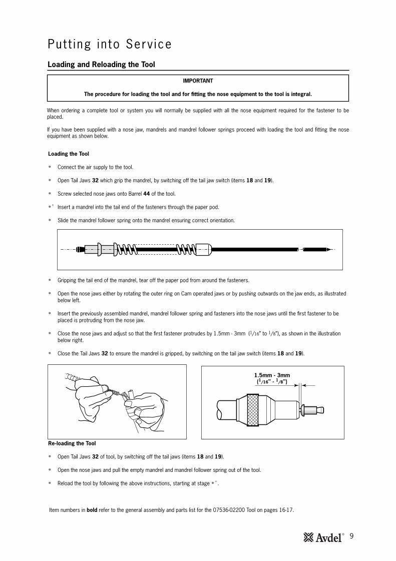
• Slide the mandrel follower spring onto the mandrel ensuring correct orientation.
• Gripping the tail end of the mandrel, tear off the paper pod from around the fasteners.
• Open the nose jaws either by rotating the outer ring on Cam operated jaws or by pushing outwards on the jaw ends, as illustrated below left.
• Insert the previously assembled mandrel, mandrel follower spring and fasteners into the nose jaws until the first fastener to beplaced is protruding from the nose jaw.
• Close the nose jaws and adjust so that the first fastener protrudes by 1.5mm - 3mm (1/16” to 1/8”), as shown in the illustration below right.
• Close the Tail Jaws 32 to ensure the mandrel is gripped, by switching on the tail jaw switch (items 18 and 19).
Re-loading the Tool
• Open Tail Jaws 32 of tool, by switching off the tail jaws (items 18 and 19).
• Open the nose jaws and pull the empty mandrel and mandrel follower spring out of the tool.
• Reload the tool by following the above instructions, starting at stage •*.
1.5mm - 3mm(1/16" - 1/8")
10
Put t i ng in to Serv ice
• Push the fastener, protruding from the nose jaws, fully into the application holes ensuring that the tool is held square.
• Operate the trigger without releasing - the mandrel head is pulled through the fastener, forming the fastener into the application.
• Remove the tool.
• Release the trigger. The next fastener will be automatically presented through the nose jaws, ready for placing.
IMPORTANT
You must check that the cursor orientation and the nose equipment are correct before attempting to operate the tool.
Item numbers in bold refer to the general assembly and parts list for the 07536-02200 on pages 16-17.
Operat ing Procedure
Setting the Tool - Adjustable Nose Assemblies Only
Insert the previously assembled mandrel (see Loading the Tool •*) or the disposable mandrel against the stop within the Tail Jaw Piston
Assembly 60.
While holding the mandrel, close the Tail Jaws 32, which grip the mandrel, by switching on the tail jaw switch (18 and 19).
Screw the lock nut onto the Barrel 44 of the tool.
Rotate the nose assembly onto the Barrel 44.
Adjust the nose assembly so that the first fastener protrudes by 1,5mm-3mm (1/16”-1/8”), as shown in the illustration on page 9.
Tighten the lock nut against the nose assembly to prevent the nose jaw assembly from moving.
Loading and Re-loading the Tool
Re-loading the Tool
Open the tail jaws of the tool, by switching off the tail jaw switch (18-19).
Open the jaws and pull the empty mandrel and follower spring out of the tool.
Insert the new mandrel against the stop within the too, and close the Tail Jaws 32 which grip the mandrel, by switching on the tail jaw
switch (18 and 19).
Close the Tail Jaws 32.

11
Dai ly
Pneumat ic Contro l Box
Weekly
Moly L i th ium Grease EP 3753 Safety Data
Serv ic ing the Too l
I M P O R T A N TThe employer is responsible for ensuring that tool maintenance instructions are given to the appropriate personnel.
The operator should not be involved in maintenance or repair of the tool unless properly trained.
I M P O R T A N TUnder no circumstances must the pneumatic box be opened. The box is a closed item.
The internal adjustments are preset and must not be altered or tampered with. Only Authorised Avdel personnel may dismantle this control box.
Grease can be ordered as a single item, the part number is shown in the Service Kit page 12.
First Aid
SKIN:
As the grease is completely water resistant it is best removed with an approved emulsifying skin cleaner.
INGESTION:
Ensure the individual drinks 30ml Milk of Magnesia, preferably in a cup of milk.
EYES:
Irritant but not harmful. Irrigate with water and seek medical attention.
Fire
FLASH POINT: Above 220°C.
Not classified as flammable.
Suitable extinguishing media: CO2, Halon or water spray if applied by an experienced operator.
Environment
Scrape up for burning or disposal on approved site.
Handling
Use barrier cream or oil resistant gloves.
Storage
Away from heat and oxidising agent.
Regular servicing should be carried out and a comprehensive inspection performed annually or every 500,000 cycles, whichever issooner.
• Daily, before use or when first putting the tool into service. Pour a few drops of clean lubricating oil into the air inlet of theintensifier if no lubricator is fitted on air supply. If the tool is in continuous use, the air hose should be disconnected from the mainair supply and the tool lubricated every two to three hours.
• Check for air and oil leaks. If damaged, hoses and couplings should be replaced.• If there is no filter on the pressure regulator, bleed the airline to clear it of accumulated dirt or water before connecting the air
hose to the intensifier. If there is a filter, drain it.• Check that the nose equipment is correct.• Check mandrels regularly for signs of wear or damage monitoring the number of placings (read the safety instructions on page 4).
• Conduct the full “Daily” procedures as described above.• Remove, inspect, clean and grease the Tail Jaws (refer to “Tail Jaw Cylinder” in the "Maintenance Section" page 14).• Check oil level in the intensifier Unit reservoir is approximately 12mm (1/2”) below the transparent cover plate.

12
ITEM PART Nº DESCRIPTION Nº OFF
07900-00157 CIRCLIP PLIERS 107900-00006 SPATULA 107900-00446 EXTRACTOR 107900-00603 BARREL VICE JAWS 107900-00520 3/8" ROD 107900-00521 1/4" ROD 107900-00602 'O' RING ASSEMBLY BULLET 107900-00595 18mm SPANNER 107900-00434 32mm SPANNER 107900-00237 3/8" x 5/16" B.S.W. SPANNER 107900-00012 9/16" x 5/8" SPANNER 107900-00008 7/16" x 1/2" SPANNER 1
SERVICE KITITEM PART Nº DESCRIPTION Nº OFF
07900-00352 SEAL REMOVAL HOOK 107900-00710 BARREL PLUG REMOVAL SPANNER 107900-00725 BULLET 107900-00243 SCREWDRIVER 107900-00717 INTENSIFIER SPANNER 107900-00013 1/8" ALLEN KEY 107900-00617 LOCTITE® MULTI-GASKET 574 50ml PACK 107900-00469 2.5mm ALLEN KEY 107900-00351 3mm ALLEN KEY 107900-00224 4mm ALLEN KEY 107900-00225 5mm ALLEN KEY 107992-00020 80g TIN MOLY LITHIUM GREASE EP 3753 1
Serv ic ing the Too lService Kit
For all servicing we recommend the use of the Service Kit (part number 07900-05300).
Note: Spanner sizes are measured 'across flats' unless otherwise specified.
13
A i r Cursor Too l , I n tens i f ie r & Cont ro l Box Assembly
07536-02100
4 5
9
2
6
3
7 8
1BLUE PIPE
BLACK PIPE
PART SECTION 'A-A'(PROTECTION PLATE REMOVED)
A A
CURSOR TAIL JAWS SIGNAL
SILVERPIPE
GREENPIPE
WHITEPIPE
74405-12080
14
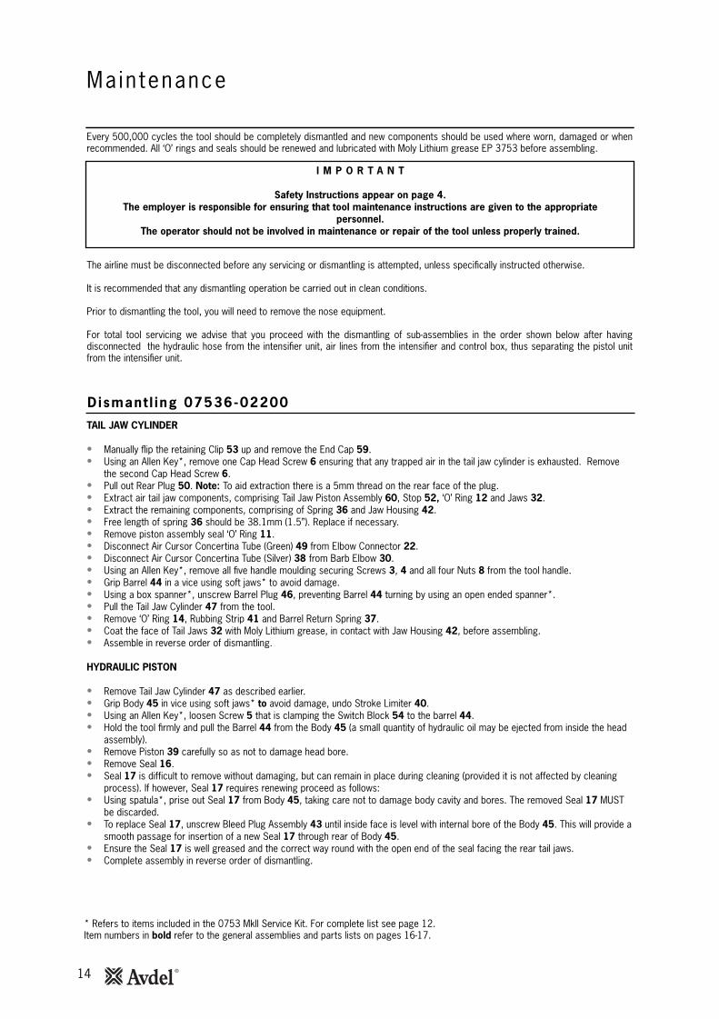
Ma in tenance
Every 500,000 cycles the tool should be completely dismantled and new components should be used where worn, damaged or whenrecommended. All ‘O’ rings and seals should be renewed and lubricated with Moly Lithium grease EP 3753 before assembling.
I M P O R T A N T
Safety Instructions appear on page 4.The employer is responsible for ensuring that tool maintenance instructions are given to the appropriate
personnel. The operator should not be involved in maintenance or repair of the tool unless properly trained.
The airline must be disconnected before any servicing or dismantling is attempted, unless specifically instructed otherwise.
It is recommended that any dismantling operation be carried out in clean conditions.
Prior to dismantling the tool, you will need to remove the nose equipment.
For total tool servicing we advise that you proceed with the dismantling of sub-assemblies in the order shown below after havingdisconnected the hydraulic hose from the intensifier unit, air lines from the intensifier and control box, thus separating the pistol unitfrom the intensifier unit.
TAIL JAW CYLINDER
• Manually flip the retaining Clip 53 up and remove the End Cap 59.• Using an Allen Key*, remove one Cap Head Screw 6 ensuring that any trapped air in the tail jaw cylinder is exhausted. Remove
the second Cap Head Screw 6.• Pull out Rear Plug 50. Note: To aid extraction there is a 5mm thread on the rear face of the plug.• Extract air tail jaw components, comprising Tail Jaw Piston Assembly 60, Stop 52, ‘O’ Ring 12 and Jaws 32.• Extract the remaining components, comprising of Spring 36 and Jaw Housing 42.• Free length of spring 36 should be 38.1mm (1.5”). Replace if necessary.• Remove piston assembly seal ‘O’ Ring 11.• Disconnect Air Cursor Concertina Tube (Green) 49 from Elbow Connector 22.• Disconnect Air Cursor Concertina Tube (Silver) 38 from Barb Elbow 30.• Using an Allen Key*, remove all five handle moulding securing Screws 3, 4 and all four Nuts 8 from the tool handle.• Grip Barrel 44 in a vice using soft jaws* to avoid damage.• Using a box spanner*, unscrew Barrel Plug 46, preventing Barrel 44 turning by using an open ended spanner*.• Pull the Tail Jaw Cylinder 47 from the tool.• Remove ‘O’ Ring 14, Rubbing Strip 41 and Barrel Return Spring 37.• Coat the face of Tail Jaws 32 with Moly Lithium grease, in contact with Jaw Housing 42, before assembling.• Assemble in reverse order of dismantling.
HYDRAULIC PISTON
• Remove Tail Jaw Cylinder 47 as described earlier.• Grip Body 45 in vice using soft jaws* to avoid damage, undo Stroke Limiter 40.• Using an Allen Key*, loosen Screw 5 that is clamping the Switch Block 54 to the barrel 44.• Hold the tool firmly and pull the Barrel 44 from the Body 45 (a small quantity of hydraulic oil may be ejected from inside the head
assembly).• Remove Piston 39 carefully so as not to damage head bore.• Remove Seal 16.• Seal 17 is difficult to remove without damaging, but can remain in place during cleaning (provided it is not affected by cleaning
process). If however, Seal 17 requires renewing proceed as follows:• Using spatula*, prise out Seal 17 from Body 45, taking care not to damage body cavity and bores. The removed Seal 17 MUST
be discarded.• To replace Seal 17, unscrew Bleed Plug Assembly 43 until inside face is level with internal bore of the Body 45. This will provide a
smooth passage for insertion of a new Seal 17 through rear of Body 45.• Ensure the Seal 17 is well greased and the correct way round with the open end of the seal facing the rear tail jaws.• Complete assembly in reverse order of dismantling.
* Refers to items included in the 0753 Mkll Service Kit. For complete list see page 12.Item numbers in bold refer to the general assemblies and parts lists on pages 16-17.
Dismant l ing 07536-02200
15
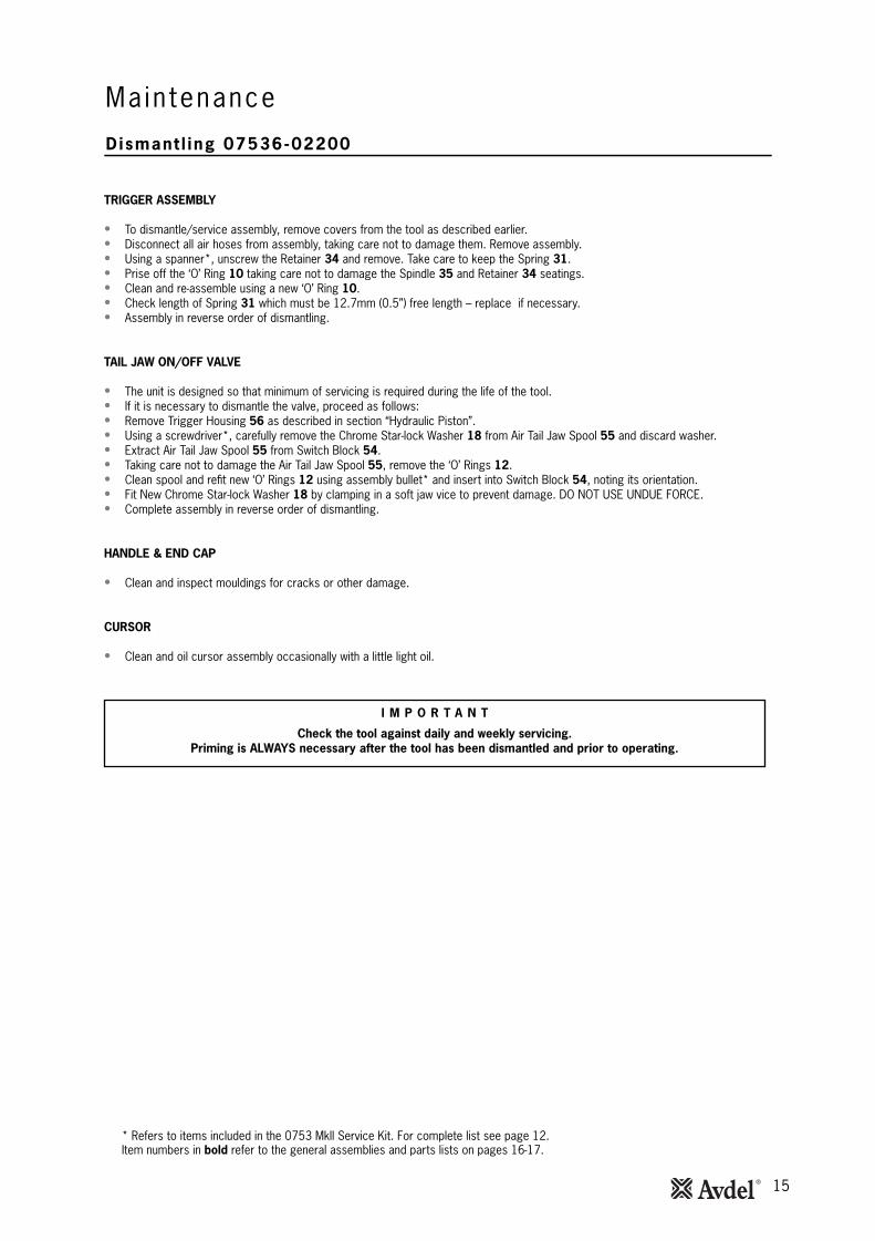
Dismant l ing 07536-02200
Main tenance
TRIGGER ASSEMBLY
• To dismantle/service assembly, remove covers from the tool as described earlier.• Disconnect all air hoses from assembly, taking care not to damage them. Remove assembly.• Using a spanner*, unscrew the Retainer 34 and remove. Take care to keep the Spring 31.• Prise off the ‘O’ Ring 10 taking care not to damage the Spindle 35 and Retainer 34 seatings.• Clean and re-assemble using a new ‘O’ Ring 10.• Check length of Spring 31 which must be 12.7mm (0.5”) free length – replace if necessary.• Assembly in reverse order of dismantling.
TAIL JAW ON/OFF VALVE
• The unit is designed so that minimum of servicing is required during the life of the tool.• If it is necessary to dismantle the valve, proceed as follows:• Remove Trigger Housing 56 as described in section “Hydraulic Piston”.• Using a screwdriver*, carefully remove the Chrome Star-lock Washer 18 from Air Tail Jaw Spool 55 and discard washer.• Extract Air Tail Jaw Spool 55 from Switch Block 54.• Taking care not to damage the Air Tail Jaw Spool 55, remove the ‘O’ Rings 12.• Clean spool and refit new ‘O’ Rings 12 using assembly bullet* and insert into Switch Block 54, noting its orientation.• Fit New Chrome Star-lock Washer 18 by clamping in a soft jaw vice to prevent damage. DO NOT USE UNDUE FORCE.• Complete assembly in reverse order of dismantling.
HANDLE & END CAP
• Clean and inspect mouldings for cracks or other damage.
CURSOR
• Clean and oil cursor assembly occasionally with a little light oil.
* Refers to items included in the 0753 Mkll Service Kit. For complete list see page 12.Item numbers in bold refer to the general assemblies and parts lists on pages 16-17.
I M P O R T A N T
Check the tool against daily and weekly servicing.Priming is ALWAYS necessary after the tool has been dismantled and prior to operating.
16
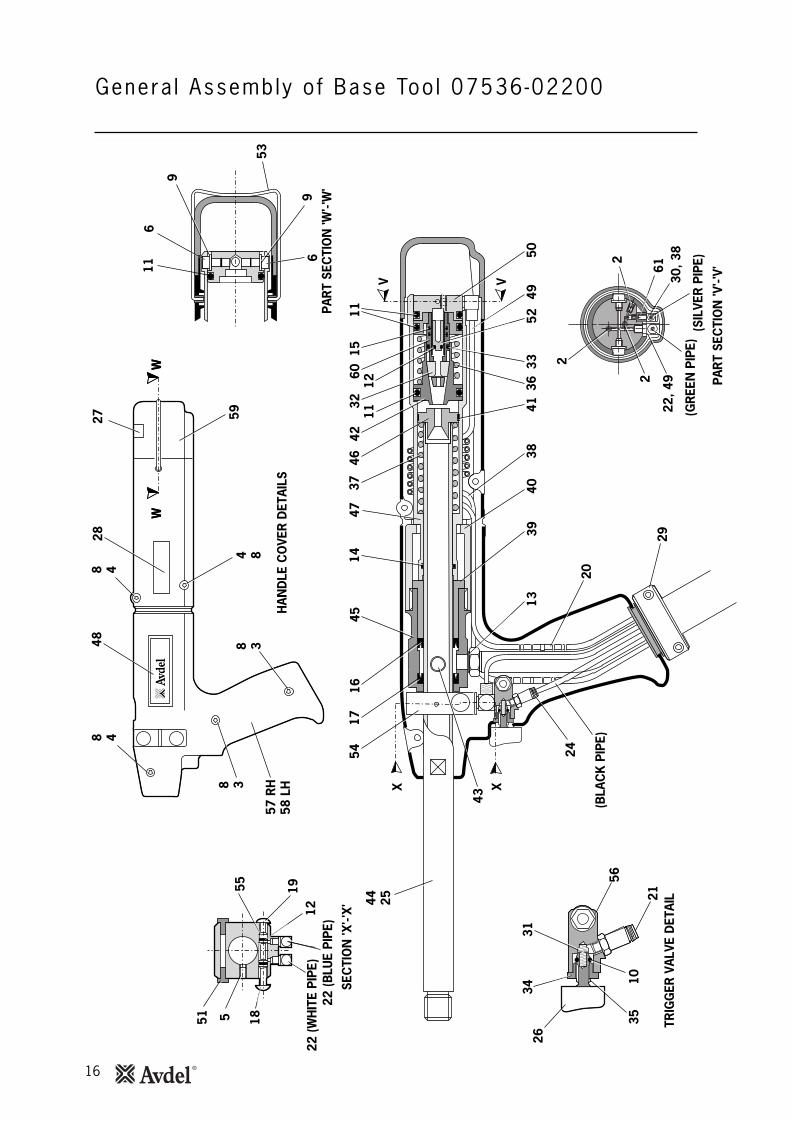
Genera l Assembly o f Base Too l 07536-022008 4
8 4
4 88 3
8 3
48
HAN
DLE
CO
VER
DET
AILS
WW
1444 25
1754
4637
3242
1211
11
V V
1516
4547
60
3941
3349
36
2
(GR
EEN
PIP
E)(S
ILVE
R P
IPE)
5238
40
29
2024
PAR
T SE
CTI
ON
'W'-'
W'
PAR
T SE
CTI
ON
'V'-'
V'
6
9
69
53
X X
TRIG
GER
VAL
VE D
ETAI
L
35
26
21
3431
5610
5013
2827 59
57 R
H58
LH
43
11
551 18
SEC
TIO
N 'X
'-'X'
55 1912
22 (B
LUE
PIPE
)22
(WH
ITE
PIPE
)
(BLA
CK
PIP
E)
WW
6130
, 38
22, 4
92
2

17
Par ts L is t for Base Too l 07536-02200
107
007-
0039
2C
ABLE
TIE
(NO
T SH
OW
N)
1-
207
001-
0049
9M
3x5
LON
G S
OC
KET
SET
SCRE
W3
-3
0700
1-00
262
M4x
22 L
ON
G S
OC
KET
HEA
D C
AP S
CRE
W1
-4
0700
1-00
401
M4x
10 L
ON
G S
OC
KET
HEA
D C
AP S
CRE
W4
-5
0700
1-00
404
M5x
6 LO
NG
SO
CKE
T H
EAD
SET
SC
REW
1-
607
001-
0050
4M
4x6
LON
G S
OC
KET
HEA
D C
AP S
CRE
W2
27 8
0700
2-00
134
M4
HEX
NU
T4
-9
0700
2-00
153
M4
WAS
HER
[PLA
STIC
]2
-10
0700
3-00
022
'O' R
ING
1-
1107
003-
0011
3'O
' RIN
G3
312
0700
3-00
121
'O' R
ING
33
1307
003-
0014
21/
8" B
SP B
ON
DED
SEA
L1
114
0700
3-00
167
'O' R
ING
11
1507
003-
0038
6'O
' RIN
G2
-16
0700
3-00
236
SEAL
[DYN
AMIC
]1
117
0700
3-00
237
SEAL
[STA
TIC
]1
-18
0700
4-00
058
1/8"
STA
RLO
CK
WAS
HER
CH
ROM
E1
-19
0700
4-00
059
1/8"
STA
RLO
CK
WAS
HER
BLA
CK
1-
2007
005-
1007
33M
M C
ON
NEC
TOR
1-
2107
005-
0135
7C
OLL
ET T
YPE
CO
NN
ECTO
R1
-22
0700
5-01
571
0753
6-02
216
ELB
OW
CO
NN
ECTO
RLO
CKN
UT
3 1- -
23 2407
005-
1007
42M
M C
ON
NEC
TOR
1-
2507
007-
0001
7D
UST
CAP
1-
2607
007-
0030
0TR
IGG
ER B
UTT
ON
1-
2707
007-
0150
3B
OO
K SY
MB
OL
LAB
EL1
-28
0700
7-01
504
CE
MAR
K LA
BEL
1-
2907
008-
0043
8FL
EXIB
LE H
OSE
ASS
EMB
LY1
-30
0700
5-01
323
M3
BAR
B E
LBO
W1
-31
0712
5-00
215
SPRI
NG
1-
3207
151-
0040
3TA
IL J
AWS
1 pa
ir2
3307
003-
0001
6'O
' RIN
G1
3407
220-
0080
3RE
TAIN
ER1
-35
0724
1-00
208
SPIN
DLE
1-
3607
154-
0040
4SP
RIN
G1
-37
0749
0-03
002
BAR
REL
RETU
RN S
PRIN
G1
-38
0753
6-02
211
3MM
AIR
CU
RSO
R C
ON
CER
TIN
A TU
BE
- SIL
VER
1-
3907
536-
0020
3PI
STON
1-
4007
530-
0020
4ST
ROKE
LIM
ITER
1-
4107
530-
0020
6RU
BB
ING
STR
IP1
142
0753
6-00
208
JAW
HO
USI
NG
1-
4307
530-
0050
0B
LEED
PLU
G A
SSEM
BLY
[ITE
MS
62 T
O 6
5]
1-
4407
536-
0220
1B
ARRE
L1
-45
0753
0-02
202
BODY
1-
4607
530-
0220
5B
ARRE
L PL
UG
1-
4707
536-
0220
7TA
IL J
AW C
YLIN
DER
1-
4807
530-
0221
0LA
BEL
2-
4907
536-
0221
24M
M A
IR C
URS
OR
CO
NC
ERTI
NA
TUB
E - G
REEN
1-
5007
536-
0221
3RE
AR P
LUG
1-
5107
530-
0031
0BL
ANKI
NG
PLU
G2
-52
0753
6-02
214
STO
P1
-53
0753
0-02
220
CLIP
1-
5407
530-
0230
1SW
ITCH
BLO
CK1
-55
0753
0-02
302
AIR
TAIL
JAW
SPO
OL
1-
5607
530-
0231
1TR
IGG
ER H
OU
SIN
G1
-57
0753
6-02
601
HAN
DLE
MO
ULD
ING
ASS
EMB
LY R
IGH
T H
AND
1-
5807
536-
0260
2H
AND
LE M
OU
LDIN
G A
SSEM
BLY
LEF
T H
AND
1-
5907
530-
0260
3EN
D C
AP1
-60
0753
6-02
800
TAIL
JAW
PIS
TON
ASS
EMB
LY1
-61
0753
6-02
215
FITT
ING
AD
APTE
R1
-62
0700
3-00
142
BO
ND
ED S
EAL
(NO
T SH
OW
N)
11
6307
003-
0019
4 B
ON
DED
SEA
L (N
OT
SHO
WN
)1
164
0700
1-00
442
SC
REW
(NO
T SH
OW
N)
11
6507
530-
0050
1 P
LUG
(NO
T SH
OW
N)
1-
ITEM
PART
N˚
DES
CR
IPTI
ON
QTY
SPAR
ESIT
EMPA
RT N̊
D
ESC
RIP
TIO
NQ
TYSP
ARES
0753
6-02
200
PA
RTS
LIS
TS

18
Dismant l ing Ins t ruct ions
I n tens i f ie r 07531-02200 - Ma in tenance
• When dismantling the intensifier assembly, first disconnect the air supply hose to intensifier inlet Connector 22.• Using an Allen Key* undo four Screws 27 and remove Protection Plate 24.• Disconnect the trigger hose 47 from the intensifier Valve 43 or 48 by depressing the outlet collet and withdrawing the hose.• Remove Cover Plate 4 and Gasket 35 by removing Screws 37 and Washers 36 using Allen Key*.• Ensure that gasket is not damaged to ensure a proper seal on assembly.• Invert intensifier assembly and drain oil from reservoir into a suitable container.• Remove Quick Release Connector 32 together with Connector 31 and Seals 33 with suitable spanner*.• Remove intensifier Valve 43 or 48 by removing the fixing screws with a suitable spanner taking care to retain ‘O’ Ring 21 located
in the Intensifier Body Casting.• Remove Screw 19 using a suitable Allen Key* and remove Silencer Cover 16, Foam Silencer 15, Spacer 18 and Retaining Plate
20.• Pull off the 6mm Plastic Tube 41 from Vacuum Connectors 42.• From the base of the intensifier insert a 3mm Allen Key * through the two holes and unscrew the Vacuum Connectors 42. Note:
• Care must be taken as the vacuum connectors are locked and sealed in place using Loctite® 574.• If difficult to remove, the vacuum connectors can be drilled out using a 3/16” or 4.7mm diameter drill.
• To reassemble the Vacuum Connectors 42, the following procedure must be followed: -• Soak the vacuum connectors in a suitable primer, i.e. Perma Bond A905• Place a drop of Loctite® 574 in the intensifier threaded hole.• From the base of the intensifier insert the Allen Key * through the hole. Ensure that the Allen Key * is free from Loctite® 574
before inserting into the vacuum connector.• Rotate the Allen Key while applying Loctite® 574 to the base of the vacuum connector.• Screw the Vacuum connector into the intensifier, ensuring that there is sufficient Loctite® 574 at the base of the fitting such
the thread is not visible. • Using a screwdriver, carefully remove internal Retaining Ring 14. Clean and inspect groove for sign of damage.• Using Extractor*, insert male threaded end into End Cover 12 and withdraw it along with intensifier Sleeve 28 and ‘O’ Rings 10
and 13.• Insert Rod* through the connector orifice at the front of the intensifier body and tap out Piston Rod 9 and Piston Assembly.• Using a suitable Allen Key*, unscrew two Screws 25 and remove End Cover 12 from intensifier Sleeve 28.• Remove Seal Plug 7 with spanner*.• Insert rod* through connector orifice at the front of the intensifier body and push out Seal Housing 5 and associated ‘O’ rings and
lip seals.• Remove Valve Housing Assembly 34 from the main body with a suitable spanner*. Clean by blowing through with a low-pressure
air jet.• Remove Piston Rod 9 from intensifier Air Piston 11 by gripping the first 20 mm (3/4”) of the rod in a vice fitted with soft jaws,
taking care not to damage or mark the working surface.• Unscrew locking Nut 17 with a suitable spanner*.• Assemble in the reverse order of dismantling, observing the following:• Clean all parts and renew all ‘O’ rings.• Lubricate all seals using Moly Lithium grease.• Valve Housing Assembly 34 must be refitted using a thread sealing adhesive.• Assemble the Piston Assembly using a new Nut 17.• End Cover 12 must be fitted correctly inside Retaining Ring 14. The tool must not be operated if the end cover has been omitted.
* Refers to items included in the 0753 MkII Service Kit. For complete list see page 12.Item numbers in bold refer to the illustration and parts list opposite.
I M P O R T A N T
Priming is ALWAYS necessary after the tool has been dismantled and prior to operating.

19
I n tens i f ie r 07531-02200
31
33
34
6
30
35
36
1 23
45 7
89 11
1213
1415
16
17
19
18
20
21
37
39
41*
Note*Some units will not include theseitems (The required link is achievedvia internal porting).
42*22
232427
32
2829
10
38
43
2526
54
VIEW ILLUSTRATING COMPAIR VALVEVIEW ON ARROW 'A'
VIEW ON ARROW 'B'
'B'
'A'
6
484645
53 52 51
47
49
50
44
40
VIEW ILLUSTRATING FESTO VALVE
07531-02200 PARTS LISTITEM PART Nº DESCRIPTION QTY SPARESITEM PART Nº DESCRIPTION QTY SPARES
1 07003-00037 SEAL 1 12 07240-00211 FILLER SCREW 1 -3 07001-00418 BLEED SCREW 1 14 07240-00210 COVER PLATE 1 -5 71420-02006 SEAL HOUSING 1 -6 07003-00153 'O' RING 2 -7 71420-02007 SEAL PLUG 1 -8 71420-02300 BODY ASSEMBLY 1 -9 71420-02008 PISTON ROD 1 -10 07003-00182 'O' RING 1 111 07531-00202 AIR PISTON 1 -12 07531-00204 END COVER 1 -13 07003-00183 'O' RING 1 114 07004-00069 RETAINING RING 1 115 07240-00213 FOAM SILENCER 1 116 07240-00214 SILENCER COVER 1 -17 07002-00017 NUT 1 118 07240-00215 SPACER 1 -19 07001-00417 SCREW 1 120 07240-00216 RETAINING PLATE 1 -21 07003-00042 'O' RING 1 122 07005-00041 CONNECTOR 1 -23 07003-00065 WASHER 1 -24 07240-00220 PROTECTION PLATE 1 -25 07001-00375 SCREW 2 -26 07003-00238 'O' RING 1 127 07001-00396 SCREW 4 -
28 07531-00201 SLEEVE 1 -29 07003-00337 LIP SEAL 1 130 07003-00336 LIP SEAL 2 2
31 07005-00406 CONNECTOR 1 -32 07005-00759 QUICK RELEASE CONNECTOR 1 -33 07003-00142 SEAL 2 134 07240-00400 VALVE HOUSING ASSEMBLY 1 -35 07240-00209 GASKET 1 136 07002-00073 WASHER 4 137 07001-00554 SCREW 4 138 07007-01504 LABEL 1 -39 07240-00217 LABEL 1 -40 07531-00205 LABEL 2 -41 07005-00596 * 6mm PLASTIC TUBE - -42 07245-00103 * VACUUM CONNECTOR 2 -43 07005-00590 COMPAIR VALVE 1 144 07005-01431 BULKHEAD CONNECTOR 1 145 07005-00668 M5 PLUG 1 -46 07005-00670 M5 SEALING RING 1 -47 07005-01084 4mm PLASTIC TUBE (150mm) - -48 07005-01524 FESTO VALVE 1 -49 07001-00176 SCREW 3 -50 07007-00292 1/4" BSP REDCAP 1 -51 07005-00647 CONNECTOR 1 -52 07005-01085 6mm PLASTIC TUBE (150mm) - -53 07005-00855 BULKHEAD UNION 1 -54 07007-01503 LABEL 1 -
*
20
Oi l Deta i l s
Pr iming Procedure
Hysp in® VG32 and AWS 32 Oi l Safety Data
Pr im ing
Priming is ALWAYS necessary after the tool has been dismantled and prior to operating. It may also be necessary to restore the fullstroke after considerable use, when the stroke may be reduced and fasteners are not fully placed by one operation of the trigger.
I M P O R T A N T
DO NOT OPERATE THE TRIGGER WHILE THE BLEED SCREW IS REMOVEDAll operations should be carried out on a clean bench, with clean hands in a clean area.
Ensure that the new oil is perfectly clean and free from air bubbles.Care MUST be taken at all times, to ensure that no foreign matter enters the tool, or serious damage may result.
Item numbers in bold refer to the general assemblies and parts lists pages 16-19.
• Remove Screw 2 and Seal 1 from Plastic Cover plate 4 on the intensifier reservoir.• Pour the priming oil into the reservoir until it is approximately 1/2” (12mm) from the top.• Replace Screw 2 and Seal 1.• Connect the intensifier unit to the air supply. Remove screw from reservoir.• With the 07536 pistol unit fitted to the intensifier unit and held below the level of the intensifier unit, unscrew Bleed Screw 64 from
Bleed Plug Assembly 43 on the 07536 tool two turns and allow oil to flow out of the tool.• When the oil runs freely and free of air bubbles, tighten the bleed screw.• Top up the reservoir on the intensifier unit with priming oil.• Cycle the tool until any air bubbles present in the oil are expelled into the oil reservoir.
The recommended oil for priming is Hyspin® VG32 and AWS 32 available in 0.5l (part number 07992-00002) or one gallon containers(part number 07992-00006). Please see safety data below.
First AidSKIN:Wash thoroughly with soap and water as soon as possible. Casual contact requires no immediate attention. Short term contactrequires no immediate attention.INGESTION:Seek medical attention immediately. DO NOT induce vomiting.EYES:Irrigate immediately with water for several minutes. Although NOT a primary irritant, minor irritation may occur following contact.
FireSuitable extinguishing media: CO2, dry powder, foam or water fog. DO NOT use water jets.
EnvironmentWASTE DISPOSAL: Through authorised contractor to a licensed site. May be incinerated. Used product may be sent for reclamation.SPILLAGE: Prevent entry into drains, sewers and water courses. Soak up with absorbent material.
HandlingWear eye protection, impervious gloves (e.g. of PVC) and a plastic apron. Use in well ventilated area.
StorageNo special precautions.
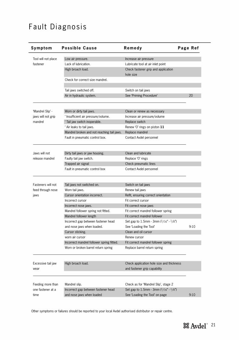
21
Tool will not place Low air pressure. Increase air pressure
fastener Lack of lubrication. Lubricate tool at air inlet point
High broach load. Check fastener grip and application
hole size
Check for correct size mandrel.
Worn or broken tail jaws. New tail jaws
Tail jaws switched off. Switch on tail jaws
Air in hydraulic system. See ‘Priming Procedure’ 20
‘Mandrel Slip’ - Worn or dirty tail jaws. Clean or renew as necessary
jaws will not grip ’ Insufficient air pressure/volume. Increase air pressure/volume
mandrel ’ Tail jaw switch inoperable. Replace switch
’ Air leaks to tail jaws. Renew ‘O’ rings on piston 11
Mandrel broken and not reaching tail jaws. Replace mandrel
Fault in pneumatic control box. Contact Avdel personnel
Jaws will not Dirty tail jaws or jaw housing. Clean and lubricate
release mandrel Faulty tail jaw switch. Replace ‘O’ rings
Trapped air signal Check pneumatic lines
Fault in pneumatic control box Contact Avdel personnel
Fasteners will not Tail jaws not switched on. Switch on tail jaws
feed through nose Worn tail jaws. Renew tail jaws
jaws Cursor orientation incorrect. Refit, ensuring correct orientation
Incorrect cursor Fit correct cursor
Incorrect nose jaws. Fit correct nose jaws
Mandrel follower spring not fitted. Fit correct mandrel follower spring
Mandrel follower length Fit correct mandrel follower
Incorrect gap between fastener head Set gap to 1.5mm - 3mm (1/16” - 1/8”)
and nose jaws when loaded. See ‘Loading the Tool’ 9-10
Cursor sticking. Clean and oil cursor
worn air cursor Renew cursor
Incorrect mandrel follower spring fitted. Fit correct mandrel follower spring
Worn or broken barrel return spring Replace barrel return spring
Excessive tail jaw High broach load. Check application hole size and thickness
wear and fastener grip capability
Feeding more than Mandrel slip. Check as for ‘Mandrel Slip’, stage 2
one fastener at a Incorrect gap between fastener head Set gap to 1.5mm - 3mm (1/16” - 1/8”)
time and nose jaws when loaded See ‘Loading the Tool’ on page 9-10
Fau l t D iagnos is
Other symptoms or failures should be reported to your local Avdel authorised distributor or repair centre.
Symptom Poss ib le Cause Remedy Page Ref

22
Notes

23
Date of issue
A. Seewraj - Product Engineering Manager Automation Tools
This box contains a power tool which is inconformity with Machines Directive2006/42/EC. The ‘Declaration of Conformity’is contained within.
Dec lara t ion o f Conformi ty
We, Avdel UK Limited, Watchmead Industrial Estate, Welwyn Garden City, Hertfordshire, AL7 1LY
declare under our sole responsibility that the product:
Model 07536
Hand Tool Serial No. ................................................
Intensifier Serial No. ................................................
to which this declaration relates is in conformity with the following standards:
EN ISO 12100 - parts 1 & 2
BS EN ISO 8662 - part 6 BS EN ISO 11202
BS EN ISO 3744 BS EN 982
ISO EN 792 - part 13-2000 BS EN 983
following the provisions of the Machine Directive 2006/42/EC.
Since 1 936 2010 Since 1922
www.avdel-global.comwww.infastech.com
02.2
011
• ©
201
0 In
fast
ech
Autosert® (equipment), Avbolt ®, Avdel®, Avdelmate®, Avdel TX2000®, Avdelok®, Avex®, Avibulb®, Avinox®, Avinut™, Avlug®, Avmatic®, Avplas®,Avseal®, Avsert®, Avtainer®, Avtronic®, Briv®, Bulbex®, Chobert®, Eurosert®, Fastriv®, Finsert®, Genesis®, Grovit®, Hemlok®, Hexsert®, Holding your world together®, Hydra®, Interlock®, Klamp-Tite ®, Klamptite KTR ®, Kvex®, Maxlok®, Monobolt®, Monobulb ®, Neobolt®, Nutsert®, Nutsert SQ®, Portariv®, Rivmatic®, Rivscrew®, Speed Fastening®, Squaresert®, Stavex®, Supersert®, Thin Sheet Nutsert®, Titan®, T-Lok®, TLR®, TSN®, TX2000®, Versa-Nut®, Viking® and Viking 360 ® are trademarks of Avdel UK Limited. Infastech™ and Our Technology, Your Success™ are trademarks of Infastech Intellectual Properties Pte Ltd. The names and logos of other companies mentioned herein may be trademarks of their respective owners. This document is for informational purposes only. Infastech makes no warranties, expressed or implied, in this document. Data shown is subject to change without prior notice as a result of continuous product development and improvement policy. Your local Avdel representative is at your disposal should you need to confirm latest information.
AUSTRALIAInfastech (Australia) Pty Ltd.891 Wellington RoadRowvilleVictoria 3178Tel: +61 3 9765 6400Fax: +61 3 9765 [email protected]
CANADAAvdel Canada Limited1030 Lorimar DriveMississaugaOntario L5S 1R8Tel: +1 905 364 0664Fax: +1 905 364 [email protected]
CHINAInfastech (China) Ltd.RM 1708, 17/F., Nanyang Plaza,57 Hung To Rd., Kwun TongHong KongTel: +852 2950 0631Fax: +852 2950 [email protected]
FRANCEAvdel France S.A.S.33 bis, rue des ArdennesBP4 75921 Paris Cedex 19Tel: +33 (0) 1 4040 8000Fax: +33 (0) 1 4208 [email protected]
GERMANYAvdel Deutschland GmbHKlusriede 2430851 LangenhagenTel: +49 (0) 511 7288 0Fax: +49 (0) 511 7288 [email protected]
INDIAInfastech Fastening Technologies India Private LimitedPlot No OZ-14, Hi Tech SEZ,SIPCOT Industrial Growth Center,Oragadam, Sriperumbudur Taluk, Kanchipuram District,602105 TamilnaduTel: +91 44 4711 8001Fax: +91 44 4711 [email protected]
ITALYAvdel Italia S.r.l.Viale Lombardia 51/5320047 Brugherio (MI)Tel: +39 039 289911Fax: +39 039 [email protected]
JAPANInfastech Kabushiki KaishaCenter Minami SKY, 3-1 Chigasaki-Chuo, Tsuzuki-ku,Yokohama-city, Kanagawa PrefectureJapan 224-0032Tel: +81 45 947 1200Fax: +81 45 947 [email protected]
MALAYSIAInfastech (Malaysia) Sdn BhdLot 63, Persiaran Bunga Tanjung 1,Senawang Industrial Park70400 SerembanNegeri SembilanTel: +606 676 7168Fax: +606 676 [email protected]
SINGAPOREInfastech (Singapore) Pte Ltd. 31 Kaki Bukit Road 3#05-03/06 TechlinkSingapore, 417818Tel: +65 6372 5653Fax: +65 6744 [email protected]
SOUTH KOREAInfastech (Korea) Ltd.212-4, Suyang-Ri,Silchon-Eup, Kwangju-City,Kyunggi-Do, Korea, 464-874Tel: +82 31 798 6340Fax: +82 31 798 [email protected]
SPAIN Avdel Spain S.A.C/ Puerto de la Morcuera, 14Poligono Industrial Prado OveraCtra. de Toledo, km 7,828919 Leganés (Madrid)Tel: +34 91 3416767Fax: +34 91 [email protected]
TAIWANInfastech/Tri-Star LimitedNo 269-7, Baodong Rd, Guanmiao Township,71841 Tainan County,Taiwan, R.O.CTel: +886 6 596 5798 (ext 201)Fax: +886 6 596 [email protected]
UNITED KINGDOMAvdel UK LimitedPacific House2 SwiftfieldsWatchmead Industrial EstateWelwyn Garden CityHertfordshire AL7 1LYTel: +44 (0) 1707 292000Fax: +44 (0) 1707 [email protected]
USAAvdel USA LLC614 NC Highway 200 SouthStanfield, North Carolina 28163Tel: +1 704 888 7100Fax: +1 704 888 [email protected]
Manual No. Issue Change Note No. Date
B2 07/103 MAR 07
B3 07/261 OCT 07
B4 08/142
B5 11/082
07900-00846