fadiga de materiais estruturais: fundamentos e aplicações
TRANSCRIPT

Fadiga de Materiais Estruturais: Fundamentos e Aplicações Crescimento de Trincas por
Fadiga(Fatigue Crack Growth)
Diego Felipe Sarzosa Burgos [email protected]

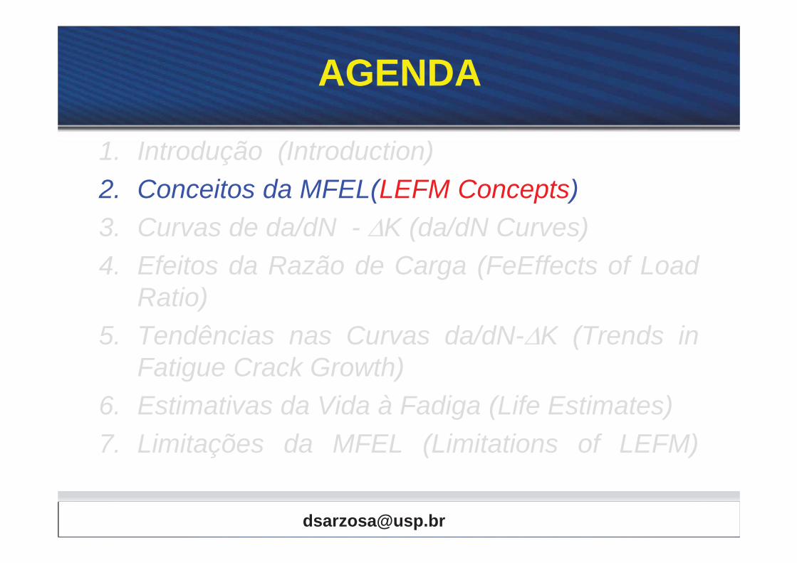
AGENDA
1. Introdução (Introduction) 2. Conceitos da MFEL(LEFM Concepts) 3. Curvas de da/dN - K (da/dN Curves) 4. Efeitos da Razão de Carga (FeEffects of Load
Ratio) 5. Tendências nas Curvas da/dN- K (Trends in
Fatigue Crack Growth) 6. Estimativas da Vida à Fadiga (Life Estimates) 7. Limitações da MFEL (Limitations of LEFM)

Mecânica da Fratura Elástica Linear
• Estudo analítico em sólidos na presença de defeitos que relaciona: – Carregamento Global. – Tamanho do Defeito. – Estado de Tensões/Deformações nas
Vizinhanças do Defeito (trinca). • Falhas (dano) estruturais governada pela
magnitude e distribuição de tensões e deformações.

Análise de Tensões para Trincas
• Fator de intensidade de tensões (Modo I)
( , )2ij i
Ijr
f OK r
TRINCA (CRACK)
Single-Parameter Description of Crack Tip Condition is the most Importante Concepts in Fracture Mechanics

Análise de Tensões para Trincas
• Campo de tensões elásticas (Modo I) 3cos 1 sin sin ...
2 2 223cos 1 sin sin ...
2 2 223cos sin cos ...
2 2 22
xx
yy
xy
I
I
I
r
r
r
K
K
K
0zz
zz xx yy
0zx yz


Análise de Tensões para Trincas
• Campo de tensões elásticas (Modo I) 3cos 1 sin sin
2 2 223cos 1 sin sin
2 2 223cos sin cos
2 2 22
xx
y
I
I
I
y
xy
K
Kr
Kr
r0zz
zz xx yy
=0
20
Ixx yy
xy
rK
Plano da Trinca = Plano Principal

Análise de Tensões para Trincas
=0
20
Ixx yy
xy
rK
O dano é controlado pelas Tensões Principais

Análise de Tensões para Trincas
2xx yyI
rKO dano é controlado pelas
Tensões Principais

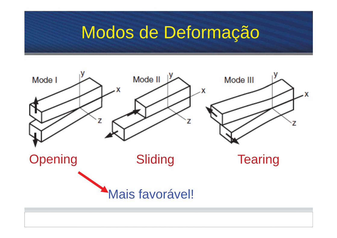
Slant Fracture vs. Flat Fracture
2ij ijK f
r
KIC is a measure of a given material to resist fracture in presence of a crack


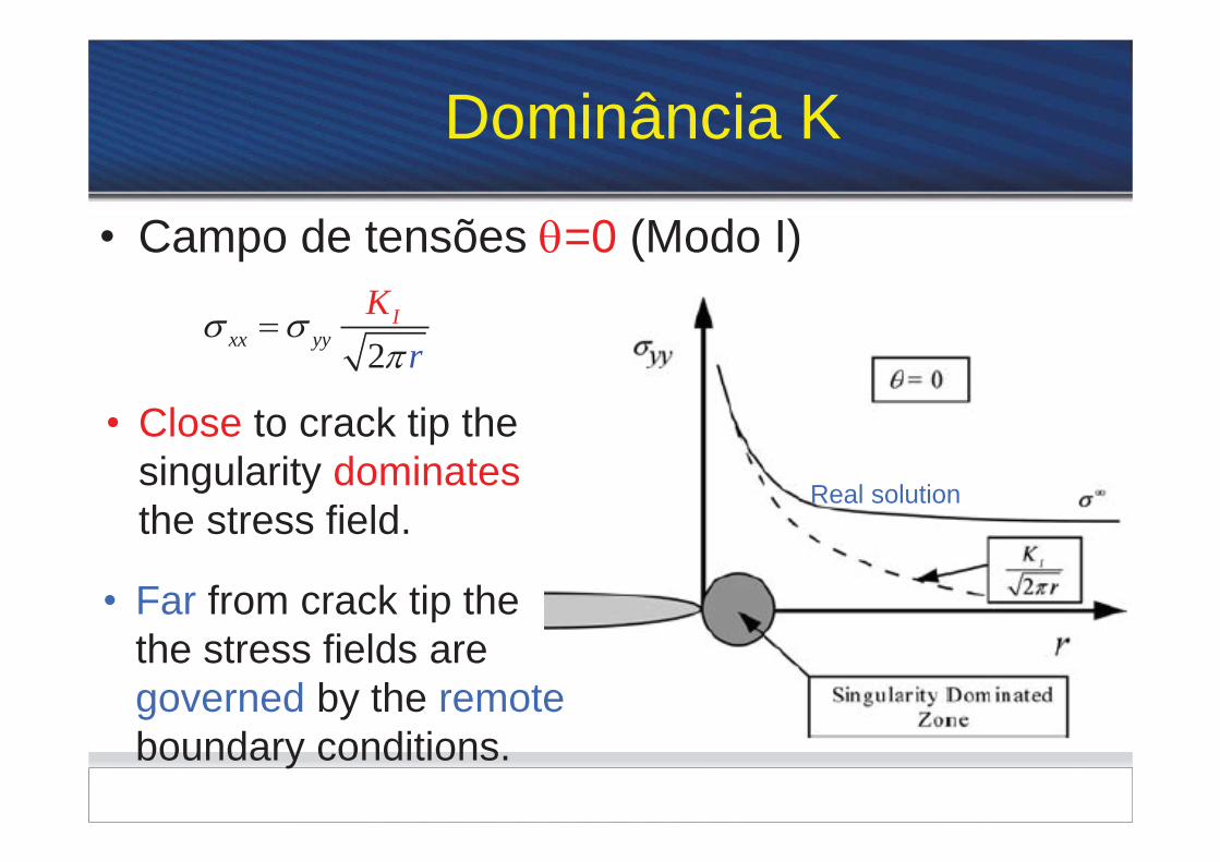
Dominância K
• Campo de tensões =0 (Modo I)
2xx yyI
rK
• Close to crack tip the singularity dominates the stress field.
• Far from crack tip the the stress fields are governed by the remote boundary conditions.
Real solution

Dominância K Região de Dominância K: A região R onde o campos de tensões/deformações são descritos pela solução elástica.
2ij ijK f
r
K define a amplitude da singularidade
ij K
K defines completely the crack tip conditions

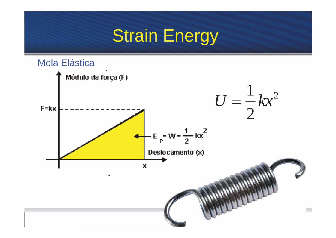

Strain Energy Release Rate (G)
12
U Pv
• Cracked body • Material behavior: Linear-elastic • Similar to linear spring:
– Potential energy U stored as result of elastic strains throught its volume
– U = Pv/2 (triangular área under P-v curve)

Strain Energy Release Rate (G)
1 dUGt da
If crack growths da Stiffness decrease U
Release of energy
Rate of change of potential energy with increase in crack área is defined as G

Strain Energy Release Rate (G)
1 dUGt da
• Change in crack área = tda
• Negative sign produces positive G value
• G characterize the energy per unit crack area required to extend the crack
• G is fundamental physical quantity controlling the behavior of the crack
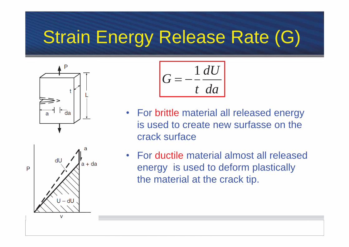
Strain Energy Release Rate (G)
1 dUGt da
• For brittle material all released energy is used to create new surfasse on the crack surface
• For ductile material almost all released energy is used to deform plastically the material at the crack tip.

Taxa de Liberação de Energia (G) 1 dUGt da
• Irwin (1956)
• G : medida da energia disponível para um incremento no tamanho da trinca.
• Devem sem “vencidas” dois tipos de resistência para a trinca incrementar seu comprimento 1. Prover energia suficiente para criar novas
superfícies; 2. Prover energia para deformar plasticamente
o material na ponta da trinca.
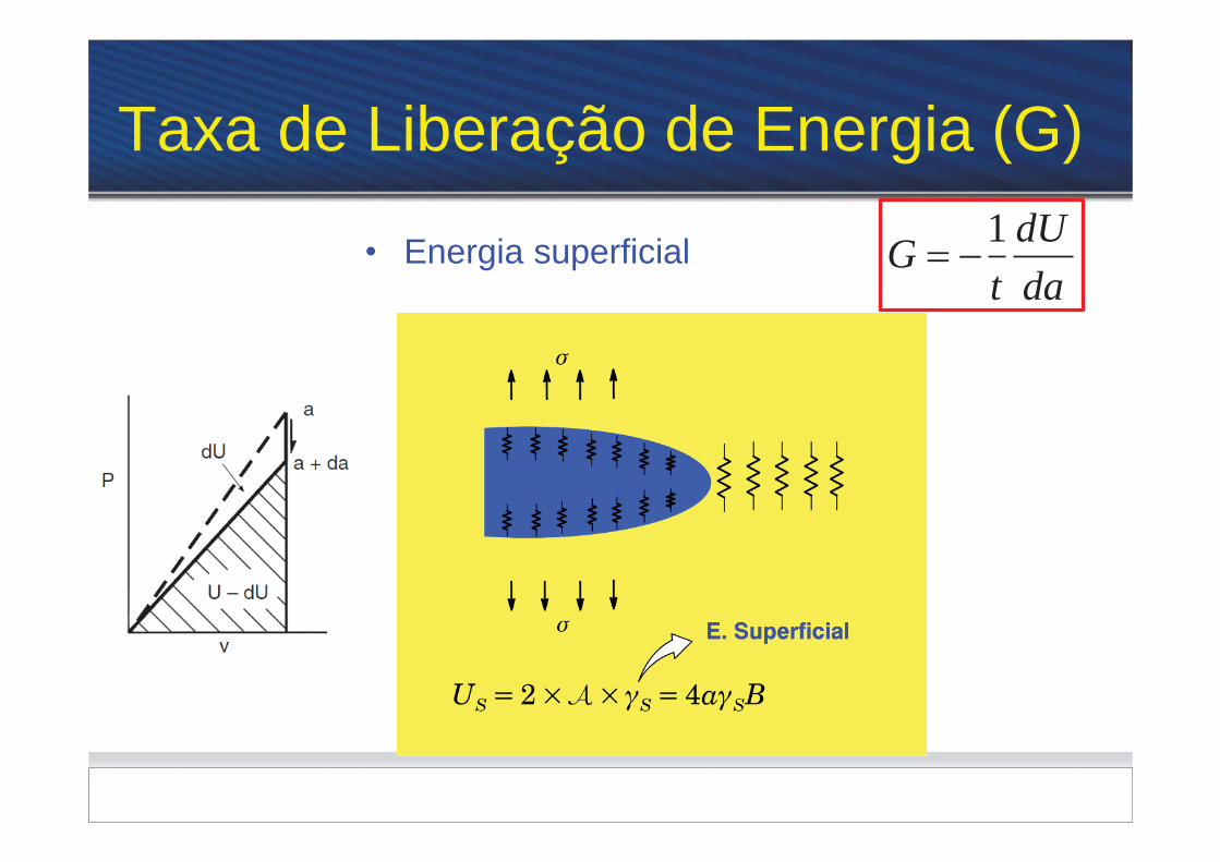
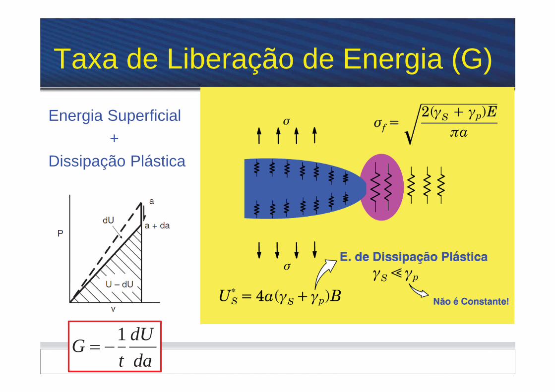
Taxa de Liberação de Energia (G)
1 dUGt da
Energia Superficial + Dissipação Plástica
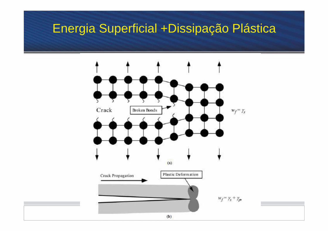

Energia Superficial +Dissipação Plástica
• Trabalho necessário a ser feito pelas forças externas para Fraturar ( incremento a do tamanho da trinca) o corpo trincado:
*
,
4
fratura s p
fratura s s p
W f
W U a B
s p :p E. Dissipação Plástica
:s E. Superficial
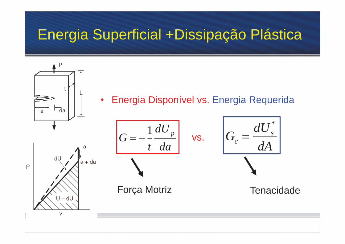
Energia Superficial +Dissipação Plástica
• Energia Disponível vs. Energia Requerida
*s
cdUGdA
1 pdUG
t davs.
Tenacidade Força Motriz


Validity of LEFM
K-fields surrounds and control the behavior of plastic zone na crack tip area
Plastic zone can be tough as a black box
K characterize the severity of crack despite the presence of limited plasticity


AGENDA
1. Introdução (Introduction) 2. Conceitos da MFEL(LEFM Concepts) 3. Curvas de da/dN - K (da/dN Curves) 4. Efeitos da Razão de Carga (FeEffects of Load
Ratio) 5. Tendências nas Curvas da/dN- K (Trends in
Fatigue Crack Growth) 6. Estimativas da Vida à Fadiga (Life Estimates) 7. Limitações da MFEL (Limitations of LEFM)

Vida à fadiga de um componente:
NT=NI+NP
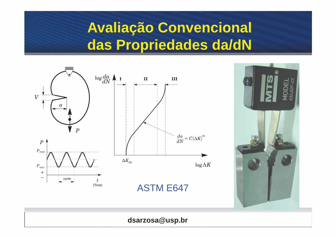
Avaliação da Vida à Fadiga
S-N or ε-N
Failure
Npropagação Niniciação
a0 LEFM
a
N
a0
Iniciação :


Need for Crack Growth Analysis
Assume that a certain structural componente may contain cracks but none are larger than a known minimum detectable length ad
Periodic Inspections are needed Damage Tolerant Design

Need for Crack Growth Analysis
Remaining Life Calculation
• Repair • Ignore • Replace
• Now or • Latter


Propagação de Trinca
• Estágio I •Fortemente Influenciada pela microestrutura
•Planos de escorregamento
•Nível de tensão
•Plasticidade na ponta da trinca •Tamanho (a) ~ 2-4 grãos (D)
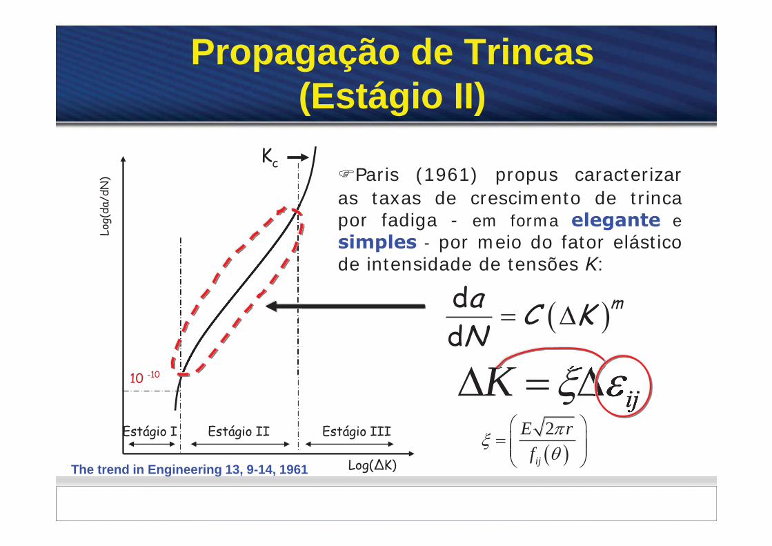
Propagação de Trincas (Estágio II)
Kc
Log(
da/d
N)
Log(ΔK)
Estágio I Estágio II Estágio III
10 -10
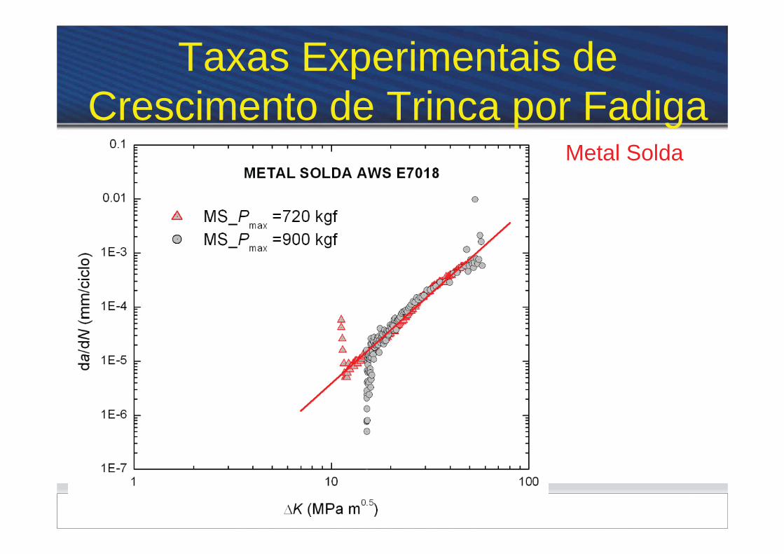
Paris (1961) propus caracterizar as taxas de crescimento de trinca por fadiga - em forma elegante e simples - por meio do fator elástico de intensidade de tensões K:
dd
ma C KN
ijK2
ij
E rf
The trend in Engineering 13, 9-14, 1961

Propagação de Trincas (Estágio II)
• Pouca influencia da resistência do material
• Zona plástica >> microestrutura do material ( pouca influência da microestrutura)


Princípio de Similaridade (Similitude)
• If the stress intesity fator K for a crack in the actual structure and in the test specimen are the same, then the fatigue crack growth response response in each case will be the same and describe by the material da/dN- K curve.
Crack


AGENDA
1. Introdução (Introduction) 2. Conceitos da MFEL(LEFM Concepts) 3. Curvas de da/dN - K (da/dN Curves) 4. Efeitos da Razão de Carga (FeEffects of Load
Ratio) 5. Tendências nas Curvas da/dN- K (Trends in
Fatigue Crack Growth) 6. Estimativas da Vida à Fadiga (Life Estimates) 7. Limitações da MFEL (Limitations of LEFM)

Life Estimation
Integration of FCGR
Prediction is very sensitive to the initial crack length
0
a
f ma
daNC K
Take into account: • R-ratio effects


Análise Numérica de Fadiga
Força Motriz Efetiva
max,( , , , )eff o jK f P P a t W
meff
da C KdN
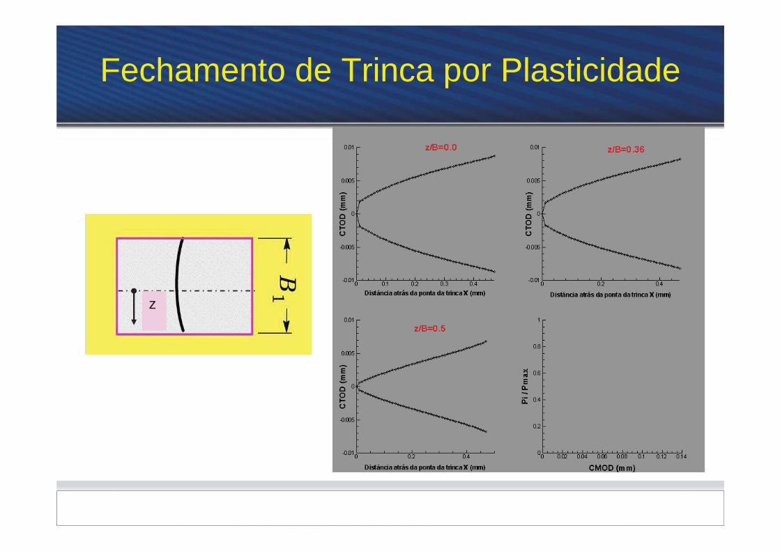
Fechamento Parcial da trinca
z

Análise Numérica de Fadiga
Propagação de defeitos
f
i
a
ma eff
daNC K
max,( , , , )eff o jK f P P a t W
0
500
1000
1500
2000
2500
3000
0 50 100 150 200 250 300 350 400# Steps
Car
rega
men
to P
[ N
]
m = P /step
Incremento constantede carga Pmax
Pmin
Pmax
Pmin


AGENDA
1. Introdução (Introduction) 2. Conceitos da MFEL(LEFM Concepts) 3. Curvas de da/dN - K (da/dN Curves) 4. Efeitos da Razão de Carga (FeEffects of Load
Ratio) 5. Tendências nas Curvas da/dN- K (Trends in
Fatigue Crack Growth) 6. Estimativas da Vida à Fadiga (Life Estimates) 7. Limitações da MFEL (Limitations of LEFM)


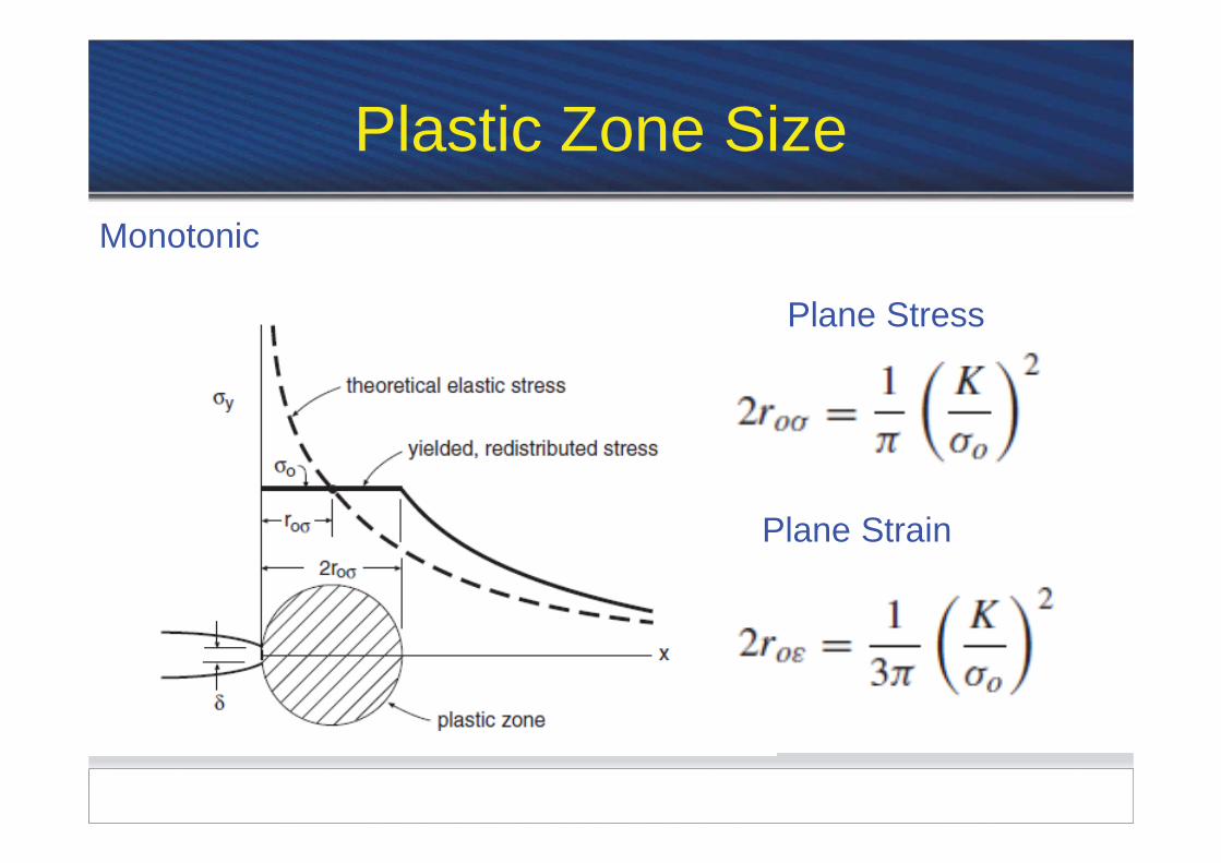
Monotonic and Cyclic Plastic Zone
Ponto 1 Still outside plastic zone Ponto 3 yielding begins with the point is inside monotonic plastic sone Ponto 5 yielding in both compression and tension when the point is inside cyclic plastic zone