civil engineering - scielo
TRANSCRIPT
405
Gilney Afonso Gonçalves et al.
REM: Int. Eng. J., Ouro Preto, 72(3), 405-414, jul. sep. | 2019
Gilney Afonso Gonçalves1,2
https://orcid.org/0000-0002-6663-8889
Ricardo Azoubel da Mota Silveira1,3
https://orcid.org/0000-0001-8955-0356
Andréa Regina Dias da Silva1,4
https://orcid.org/0000-0001-7841-8077
Jéssica Lorrany Silva1,5
https://orcid.org/0000-0001-8525-3098
1Universidade Federal de Ouro Preto – UFOP,
Escola de Minas, Departamento de Engenharia
Civil, Ouro Preto – Minas Gerias - Brasil.
E-mails: [email protected], [email protected], [email protected], [email protected], [email protected]
Inelastic second-order analysis of steel columns under minor-axis bendingAbstract
The inelastic second-order behavior of steel structural columns under minor-axis bending is presented in this article. To study this behavior, a nonlinear frame element formulation is adopted in which the steel’s plasticity process is accompanied at the nodal points of each finite element through the refined plastic-hinge method (RPHM). A tangent modulus approach is employed in order to consider the stiffness degrada-tion in function of the internal forces’ variation, and the second-order effects, residual stresses and geometric imperfections are considered in the modeling of column behav-ior. As a criterium for defining the ultimate limit state of the column cross-section, strength surfaces are adopted. These surfaces describe the interaction between the axial force and bending moment (N-M interaction diagrams). To solve the nonlinear equilibrium equation for the structural system, the Newton-Raphson method is used, coupled with continuation strategies. Columns with different slenderness, boundary and loading conditions are analyzed, and the results obtained are comparable to those found by other researchers. The results lead to the conclusion that the numerical ap-proach adopted in this study can be used for a better behavioral understanding of the steel column under weak-axis bending.
Keywords: Steel columns, inelastic second-order analysis, minor-axis bending, finite element method, refined plastic-hinge method.
http://dx.doi.org/10.1590/0370-44672018720046
Civil EngineeringEngenharia Civil
1. Introduction
Nowadays, steel material is com-monly employed in civil construction. Besides being a completely recyclable material, steel has important characteris-tics such as strength and durability, good ductility and speedy manufacturing and assembly times. For the steel member and frame structure analysis, highlighted herein is an advanced analysis that has the capacity to simultaneously evaluate its strength and stability.
In a nonlinear finite element context for steel member and frame numerical analysis, two inelastic analysis approaches are usually employed: the plastic zone
method (PZM) and the refined plastic-hinge method (RPHM). In the PZM (Clarke, 1994; Alvarenga, 2010), the cross-section of each finite element is discretized in fibers and the second order effects and residual stresses can be di-rectly considered in the analysis. Another important characteristic is that with the stress state obtained in each fiber, it is possible to monitor the gradual yielding in the cross-section. Due to the efficiency of this method, its solutions are usually treated as “exact solutions” in literature (Chen and Kim, 1997). However, the PZM is not routinely used in engineer-
ing offices, since it requires an intense computational effort. Because of this, its application is usually restricted to the simulation of simple structures that serve as comparisons and/or calibrations for the development of other numerical models and formulations.
In the RPHM (Liew et al., 1993; Chan and Chui, 2000), the consideration of material plasticity is concentrated at the nodal points of each finite element. At these nodes, the formation of plastic hinges can occur, characterizing the plasticity of the entire cross-section. This method is computationally more practical
406
Inelastic second-order analysis of steel columns under minor-axis bending
REM: Int. Eng. J., Ouro Preto, 72(3), 405-414, jul. sep. | 2019
and captures, in an approximating man-ner, the advance of the plasticity in the element cross-sections before the forma-tion of the plastic hinges. Residual stresses effects can also be considered.
The objective of this study is to use an RPHM that permits adequate model-ing for the inelastic behavior of steel col-umns with type I compact sections under weak or minor-axis bending. Although unusual, the columns where the bend-ing occurs under this axis can present important benefits such as the capacity to develop all of their plastic strength without lateral-torsional buckling (BS 5950, 2000; AISC, 2005). Besides this,
for profiles having wide flanges, the shape factor is approximately 35% greater than the referent for the major axis (Kanchana-lai and Lu, 1979).
To achieve the proposed objective, the tangent modulus equation suggested by Ziemian and McGuire (2002) is implemented in the CS ASA (Computa-tional System for Advanced Structural Analysis; Silva, 2009). In this equation, the cross-section stiffness degradation varies in function of the axial force and bending moment around the minor axis. The numerical formulation proposed also employs the strength surfaces (McGuire et al., 2000; BS 5950, 2000), adequately
evaluating the interaction between the axial force and bending moment at the minor axis. Validation of these strate-gies is made by analysis of the columns under various boundaries, slenderness and loading conditions. The results obtained are compared with analytical and numerical solutions obtained using the PZM. In this study, the second order effects are simulated, and the nonlinear solution methodology is based on the Newton-Raphson method coupled with continuation strategies. The details of this methodology are presented on the next two sections. Section 4 presents three numerical examples.
2. Inelastic formulation based on rphm
In this section, the inelastic for-mulation based on the RPHM imple-mented in CS-ASA is presented along with the main interventions made for this study. The following assumptions are considered in the column modeling: all finite elements are initially straight and prismatic and their cross-sections
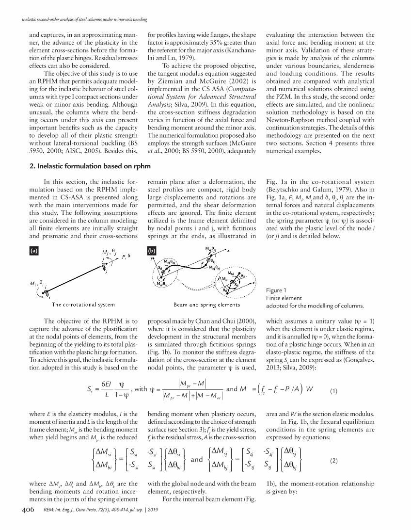
remain plane after a deformation, the steel profiles are compact, rigid body large displacements and rotations are permitted, and the shear deformation effects are ignored. The finite element utilized is the frame element delimited by nodal points i and j, with fictitious springs at the ends, as illustrated in
Fig. 1a in the co-rotational system (Belytschko and Galum, 1979). Also in Fig. 1a, P, M
i, M
j and δ, θi, θ
j are the in-
ternal forces and natural displacements in the co-rotational system, respectively; the spring parameter ψ
i (or ψ
j) is associ-
ated with the plastic level of the node i (or j) and is detailed below.
(a) (b)
Figure 1Finite element adopted for the modelling of columns.
The objective of the RPHM is to capture the advance of the plastification at the nodal points of elements, from the beginning of the yielding to its total plas-tification with the plastic hinge formation. To achieve this goal, the inelastic formula-tion adopted in this study is based on the
proposal made by Chan and Chui (2000), where it is considered that the plasticity development in the structural members is simulated through fictitious springs (Fig. 1b). To monitor the stiffness degra-dation of the cross-section at the element nodal points, the parameter ψ is used,
which assumes a unitary value (ψ = 1) when the element is under elastic regime, and it is annulled (ψ = 0), when the forma-tion of a plastic hinge occurs. When in an elasto-plastic regime, the stiffness of the spring S
s can be expressed as (Gonçalves,
2013; Silva, 2009):
61s
EIS
L= , with pr
rerp
M M
M M M M=
+ and ( )/M f f P A W=
y r
where E is the elasticity modulus, I is the moment of inertia and L is the length of the frame element; M
er is the bending moment
when yield begins and Mpr is the reduced
bending moment when plasticity occurs, defined according to the choice of strength surface (see Section 3); f
y is the yield stress,
fr is the residual stress, A is the cross-section
area and W is the section elastic modulus.In Fig. 1b, the flexural equilibrium
conditions in the spring elements are expressed by equations:
isis si si
si si ibib
M S -S
-S SM= and
jsjs sj sj
sj sj jbjb
M S -S
-S SM=
where ΔMs, Δθ
s and ΔM
b, Δθ
b are the
bending moments and rotation incre-ments in the joints of the spring element
with the global node and with the beam element, respectively.
For the internal beam element (Fig.
1b), the moment-rotation relationship is given by:
(1)
(2)
407
Gilney Afonso Gonçalves et al.
REM: Int. Eng. J., Ouro Preto, 72(3), 405-414, jul. sep. | 2019
4 215
= = +tii jj
E I PLk k
L and
230
= = tij ji
E I PLk k
L
with Et representing the tangent modulus
and L the element length.Associating the Eqs. (2) and (3), one
can arrive in the following matrix equation:
0 0
0
0
0 0
isis si si
ibib
jbjb ji sj jj sj
sj sj jsjs
M S -S
M
M k S k -S
-S SM
+=
+
Now, assuming that the loads are applied only in the global nodes of the element (ΔM
bi and ΔM
bj are
equal to zero), making some matrices algebraic manipulations and includ-ing the axial effect (frame element),
one can arrive in the following force-displacement relationship in the element co-rotational system:
0 0
0
0
2
2
EA / LP
M
or,
with b = (Ssi + k
ii) (S
sj + k
jj) - k
ji k
ij. The sub-
script c indicates the coordinate system utilized; A is the cross-section area; ΔP is the increment of axial force and Δδ
is the increment of axial deformation.The tangent modulus E
t captures,
in an approximate manner, the reduc-tion of the element’s sectional stiffness
due to the axial force. The strength equations for the columns of AISC (2005) define the variation of the tan-gent modulus as:
where E is the material modulus of elasticity, P is the active axial force, and P
y is the axial yield force. These
equations include the effect of the
initial imperfections as well as the residual stresses in the columns. However, this is only valid for axial forces of compression (P < 0). For axial
tension forces (P > 0), the strength equations for columns proposed by CRC (Galambos, 1998) can be used and are given by:
where the residual stresses effects are implicitly considered.
Ziemian and McGuire (2002) pro-
posed a modification to the equations presented in the CRC (Galambos, 1998) in which the tangent modulus varies in
function of the axial force and the bend-ing moment about the weakest axis. In this case:
where the term b is an empirical value, which, in the inelastic second-order analysis, is equal to 0.65 for members
under minor-axis bending (Ziemian and McGuire, 2002); M
y and M
Py are the
bending moment and the plastic bending
moment, both in relation to the minor axis. Using these equations in the analysis of structural members under minor-axis
(9)
(8)
(7)
(6)
(5)
(4)
=ibib ii ij
ji jj jbjb
M k k
k kM
where ΔMbi, ΔM
bj, Δθ
bi and Δθ
bj are the
bending moments and rotation incre-ments associated with the nodal points
i and j of the beam element. The terms k
ii, k
ij, k
ji and kjj are responsible for simu-
lating the bending stiffness and second-
order effects. They are defined as (Yang and Kuo, 1994):
(3)
408
Inelastic second-order analysis of steel columns under minor-axis bending
REM: Int. Eng. J., Ouro Preto, 72(3), 405-414, jul. sep. | 2019
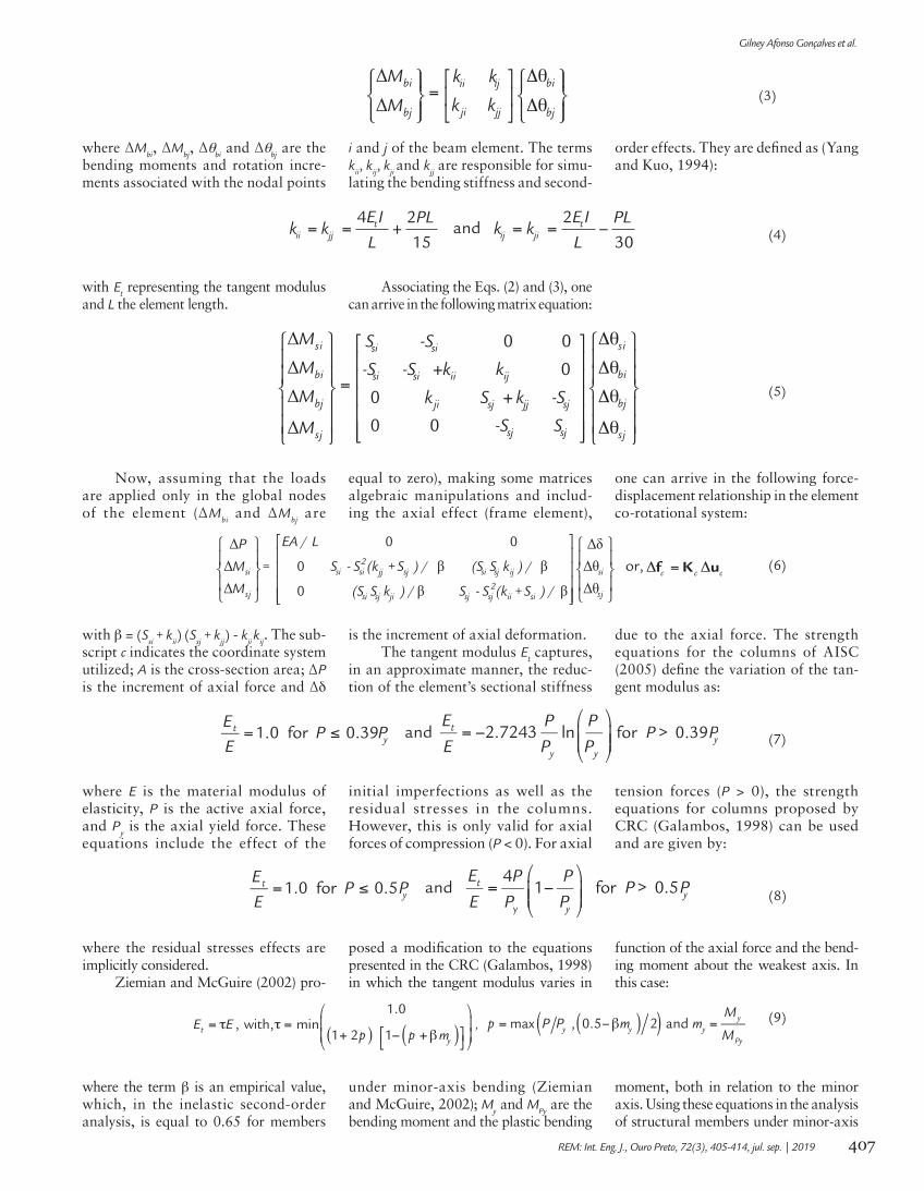
bending, Ziemian and McGuire (2002) obtained results that were compatible with
those encountered when using the PZM. Considering only the axial forces, Fig. 2
displays a comparison between the above Eqs. (7), (8) and (9).
Figure 2Tangent modulus variations.
To reach the proposed objective herein, the tangent modulus equations are utilized as indicated by Ziemian and
McGuire (2002), which depend on the axial force and moment under minor-axis bending. Since this moment is evaluated
at the i and j ends of the finite element (Fig. 1), the tangent modulus can be calculated as:
with Et,i and E
t,j representing the modified
tangent modulus at the i and j element ends, respectively.
The terms k of the stiffness ma-
trix in Eq. (6) are recalculated tak-ing to consideration that the tangent modulus varies linearly along the length of the finite element. Using
the appropriate interpolation func-tions, the first part of k
ii, k
ij, k
ji and k
jj
are redefined considering Et, through
the relationships:
(10)
(11a)
(11b)
(11c)
(12a)
Resolving the previous integrals, the coefficients kii, k
ij, k
ji and k
jj become:
(12b)
(12c)
Equation (6) is valid until the internal forces reach the section plastic strength. From then on, with the section having already suffered total plastifica-tion, the increase of the axial force, for
example, creates a condition where the strength of the section is less than that of the forces acting upon it. As such, an alteration in the force-displacement relationship is necessary so that the
strength plastic equations for the sec-tion are not violated. This alteration and the transformation of Eq. (6) into the global coordinates system is detailed in Gonçalves (2013) and Silva (2009).
409
Gilney Afonso Gonçalves et al.
REM: Int. Eng. J., Ouro Preto, 72(3), 405-414, jul. sep. | 2019
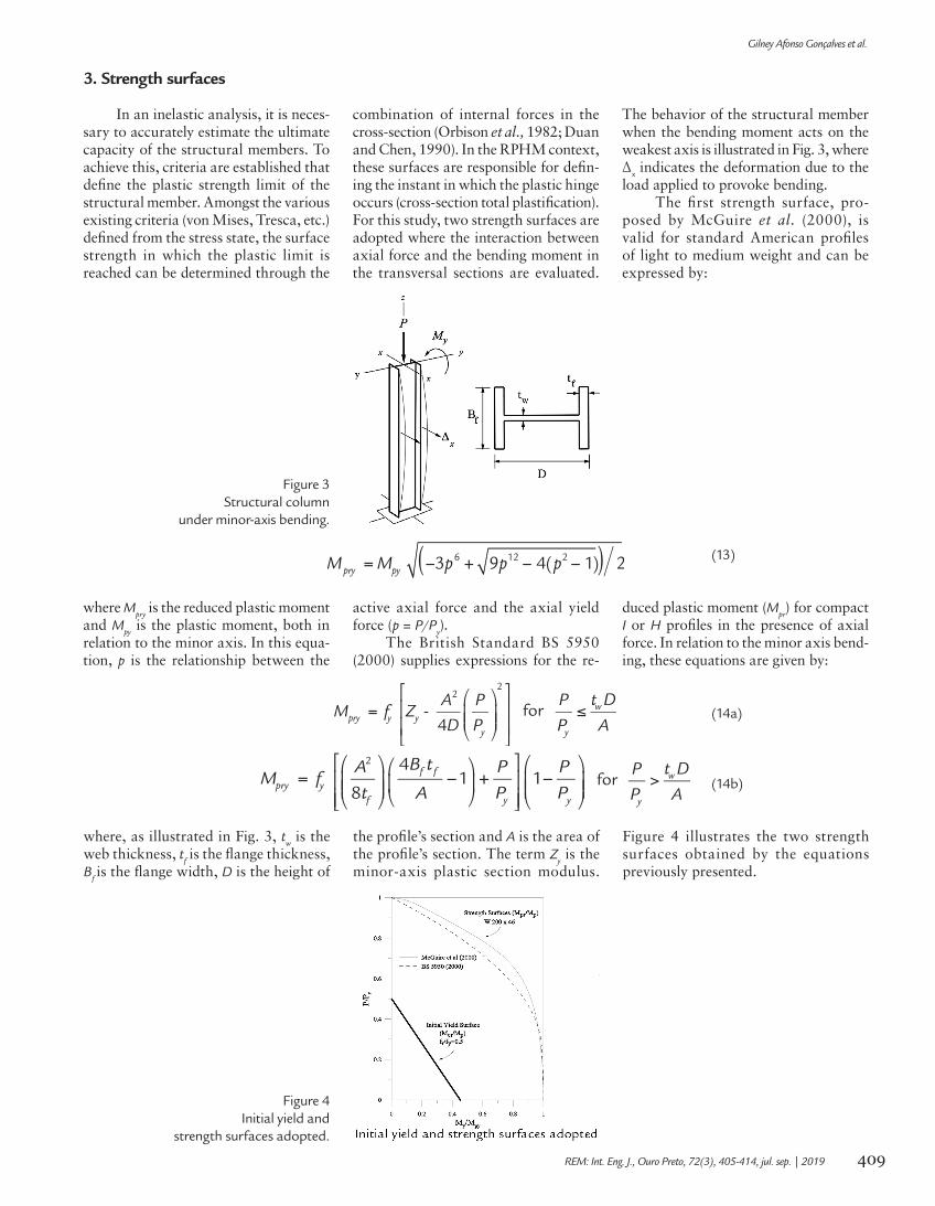
In an inelastic analysis, it is neces-sary to accurately estimate the ultimate capacity of the structural members. To achieve this, criteria are established that define the plastic strength limit of the structural member. Amongst the various existing criteria (von Mises, Tresca, etc.) defined from the stress state, the surface strength in which the plastic limit is reached can be determined through the
combination of internal forces in the cross-section (Orbison et al., 1982; Duan and Chen, 1990). In the RPHM context, these surfaces are responsible for defin-ing the instant in which the plastic hinge occurs (cross-section total plastification). For this study, two strength surfaces are adopted where the interaction between axial force and the bending moment in the transversal sections are evaluated.
The behavior of the structural member when the bending moment acts on the weakest axis is illustrated in Fig. 3, where Δx indicates the deformation due to the load applied to provoke bending.
The first strength surface, pro-posed by McGuire et al. (2000), is valid for standard American profiles of light to medium weight and can be expressed by:
Figure 3Structural column
under minor-axis bending.
3. Strength surfaces
where Mpry
is the reduced plastic moment and M
py is the plastic moment, both in
relation to the minor axis. In this equa-tion, p is the relationship between the
active axial force and the axial yield force (p = P/P
y).
The British Standard BS 5950 (2000) supplies expressions for the re-
duced plastic moment (Mpr) for compact
I or H profiles in the presence of axial force. In relation to the minor axis bend-ing, these equations are given by:
(13)
(14b)
(14a)
where, as illustrated in Fig. 3, tw is the
web thickness, tf is the flange thickness,
Bf is the flange width, D is the height of
the profile’s section and A is the area of the profile’s section. The term Z
y is the
minor-axis plastic section modulus.
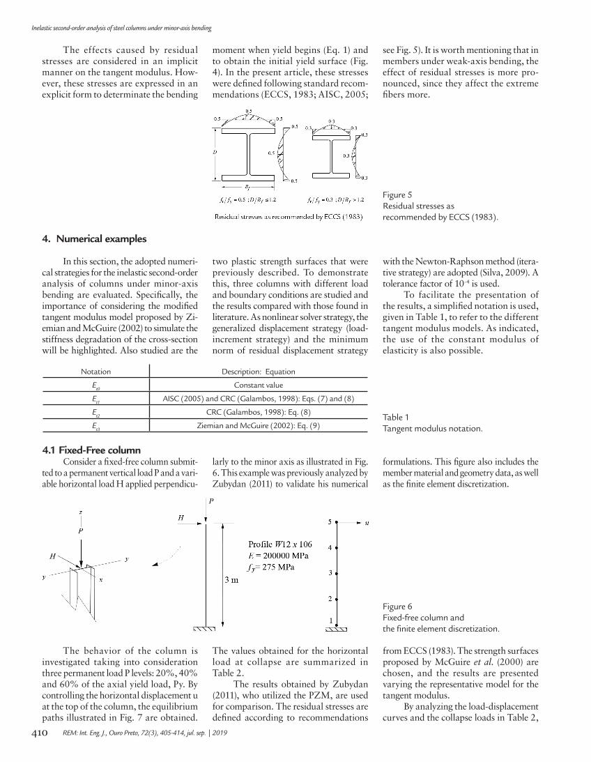
Figure 4 illustrates the two strength surfaces obtained by the equations previously presented.
Figure 4Initial yield and
strength surfaces adopted.
410
Inelastic second-order analysis of steel columns under minor-axis bending
REM: Int. Eng. J., Ouro Preto, 72(3), 405-414, jul. sep. | 2019
The effects caused by residual stresses are considered in an implicit manner on the tangent modulus. How-ever, these stresses are expressed in an explicit form to determinate the bending
moment when yield begins (Eq. 1) and to obtain the initial yield surface (Fig. 4). In the present article, these stresses were defined following standard recom-mendations (ECCS, 1983; AISC, 2005;
see Fig. 5). It is worth mentioning that in members under weak-axis bending, the effect of residual stresses is more pro-nounced, since they affect the extreme fibers more.
Figure 5Residual stresses as recommended by ECCS (1983).
4. Numerical examples
In this section, the adopted numeri-cal strategies for the inelastic second-order analysis of columns under minor-axis bending are evaluated. Specifically, the importance of considering the modified tangent modulus model proposed by Zi-emian and McGuire (2002) to simulate the stiffness degradation of the cross-section will be highlighted. Also studied are the
two plastic strength surfaces that were previously described. To demonstrate this, three columns with different load and boundary conditions are studied and the results compared with those found in literature. As nonlinear solver strategy, the generalized displacement strategy (load-increment strategy) and the minimum norm of residual displacement strategy
with the Newton-Raphson method (itera-tive strategy) are adopted (Silva, 2009). A tolerance factor of 10-4 is used.
To facilitate the presentation of the results, a simplified notation is used, given in Table 1, to refer to the different tangent modulus models. As indicated, the use of the constant modulus of elasticity is also possible.
Notation Description: Equation
Et0
Constant value
Et1
AISC (2005) and CRC (Galambos, 1998): Eqs. (7) and (8)
Et2
CRC (Galambos, 1998): Eq. (8)
Et3
Ziemian and McGuire (2002): Eq. (9)Table 1Tangent modulus notation.
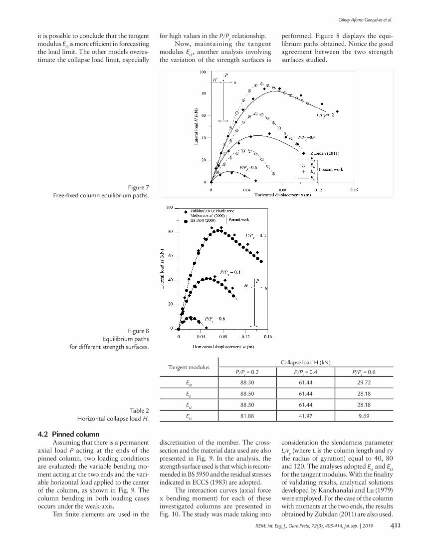
4.1 Fixed-Free columnConsider a fixed-free column submit-
ted to a permanent vertical load P and a vari-able horizontal load H applied perpendicu-
larly to the minor axis as illustrated in Fig. 6. This example was previously analyzed by Zubydan (2011) to validate his numerical
formulations. This figure also includes the member material and geometry data, as well as the finite element discretization.
Figure 6Fixed-free column and the finite element discretization.
The behavior of the column is investigated taking into consideration three permanent load P levels: 20%, 40% and 60% of the axial yield load, Py. By controlling the horizontal displacement u at the top of the column, the equilibrium paths illustrated in Fig. 7 are obtained.
The values obtained for the horizontal load at collapse are summarized in Table 2.
The results obtained by Zubydan (2011), who utilized the PZM, are used for comparison. The residual stresses are defined according to recommendations
from ECCS (1983). The strength surfaces proposed by McGuire et al. (2000) are chosen, and the results are presented varying the representative model for the tangent modulus.
By analyzing the load-displacement curves and the collapse loads in Table 2,
411
Gilney Afonso Gonçalves et al.
REM: Int. Eng. J., Ouro Preto, 72(3), 405-414, jul. sep. | 2019
it is possible to conclude that the tangent modulus E
t3 is more efficient in forecasting the load limit. The other models overes-timate the collapse load limit, especially
for high values in the P/Py relationship.
Now, maintaining the tangent modulus E
t3, another analysis involving
the variation of the strength surfaces is
performed. Figure 8 displays the equi-librium paths obtained. Notice the good agreement between the two strength surfaces studied.
Figure 7Free-fixed column equilibrium paths.
Figure 8Equilibrium paths
for different strength surfaces.
Tangent modulusCollapse load H (kN)
P/Py = 0.2 P/P
y = 0.4 P/P
y = 0.6
Et0
88.50 61.44 29.72
Et1
88.50 61.44 28.18
Et2
88.50 61.44 28.18
Et3
81.88 41.97 9.69Table 2
Horizontal collapse load H.
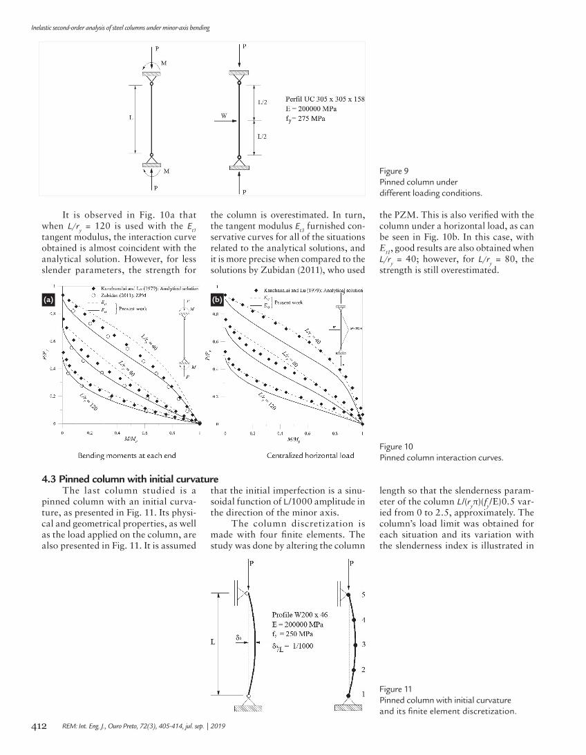
4.2 Pinned columnAssuming that there is a permanent
axial load P acting at the ends of the pinned column, two loading conditions are evaluated: the variable bending mo-ment acting at the two ends and the vari-able horizontal load applied to the center of the column, as shown in Fig. 9. The column bending in both loading cases occurs under the weak-axis.
Ten finite elements are used in the
discretization of the member. The cross-section and the material data used are also presented in Fig. 9. In the analysis, the strength surface used is that which is recom-mended in BS 5950 and the residual stresses indicated in ECCS (1983) are adopted.
The interaction curves (axial force x bending moment) for each of these investigated columns are presented in Fig. 10. The study was made taking into
consideration the slenderness parameter L/r
y (where L is the column length and ry
the radius of gyration) equal to 40, 80 and 120. The analyses adopted E
t1 and E
t3
for the tangent modulus. With the finality of validating results, analytical solutions developed by Kanchanalai and Lu (1979) were employed. For the case of the column with moments at the two ends, the results obtained by Zubidan (2011) are also used.
412
Inelastic second-order analysis of steel columns under minor-axis bending
REM: Int. Eng. J., Ouro Preto, 72(3), 405-414, jul. sep. | 2019
Figure 9Pinned column underdifferent loading conditions.
It is observed in Fig. 10a that when L/r
y = 120 is used with the E
t1
tangent modulus, the interaction curve obtained is almost coincident with the analytical solution. However, for less slender parameters, the strength for
the column is overestimated. In turn, the tangent modulus E
t3 furnished con-
servative curves for all of the situations related to the analytical solutions, and it is more precise when compared to the solutions by Zubidan (2011), who used
the PZM. This is also verified with the column under a horizontal load, as can be seen in Fig. 10b. In this case, with Et1, good results are also obtained when L/r
y = 40; however, for L/r
y = 80, the
strength is still overestimated.
(a) (b)
Figure 10Pinned column interaction curves.
4.3 Pinned column with initial curvatureThe last column studied is a
pinned column with an initial curva-ture, as presented in Fig. 11. Its physi-cal and geometrical properties, as well as the load applied on the column, are also presented in Fig. 11. It is assumed
that the initial imperfection is a sinu-soidal function of L/1000 amplitude in the direction of the minor axis.
The column discretization is made with four finite elements. The study was done by altering the column
length so that the slenderness param-eter of the column L/(r
yπ)(f
y/E)0.5 var-
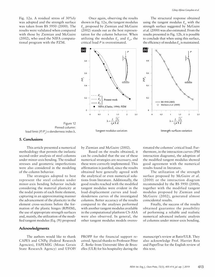
ied from 0 to 2.5, approximately. The column’s load limit was obtained for each situation and its variation with the slenderness index is illustrated in
Figure 11Pinned column with initial curvature and its finite element discretization.
413
Gilney Afonso Gonçalves et al.
REM: Int. Eng. J., Ouro Preto, 72(3), 405-414, jul. sep. | 2019
Fig. 12a. A residual stress of 30%fy was adopted and the strength surface was taken from BS 5950 (2000). The results were validated when compared with those by Ziemian and McGuire (2002), who used the NIFA computa-tional program with the PZM.
Once again, observing the results shown in Fig. 12a, the tangent modulus E
t3 proposed by Ziemian and McGuire
(2002) stands out as the best represen-tation for the column behavior. When utilizing the modulus E
t1 and E
t2, the
critical load P is overestimated.
The structural response obtained using the tangent modulus E
t3 with the
strength surface suggested by McGuire et al. (2000) was also estimated. From the results presented in Fig. 12b, it is possible to conclude that when using this surface, the efficiency of modulus E
t3 is maintained.
(a) (b)
Figure 12Pinned column:
load limit (P/Py) x slenderness index λ.
5. Conclusions
Acknowledgments
This article presented a numerical methodology that permits the inelastic second-order analysis of steel columns under minor-axis bending. The residual stresses and geometric imperfections were also considered in the modeling of the column behavior.
The strategies adopted to best represent the steel column under minor-axis bending behavior include considering the material plasticity at the nodal points of each finite element, capturing in an approximating manner the advancement of the plasticity in the element cross-sections before the for-mation of the plastic hinges (RPHM), the use of appropriate strength surfaces and, mainly, the utilization of the modi-fied tangent modulus (Eq. (9)) proposed
by Ziemian and McGuire (2002).Based on the results obtained, it
can be concluded that the use of these numerical strategies are necessary, and these were correctly implemented. This affirmation is justified, since the results obtained here generally agreed with the analytical or even numerical solu-tions from literature. Additionally, the good results reached with the modified tangent modulus were evident in the load-displacement curves and load-slenderness curves of the investigated columns. Better accuracy of the results compared to the analyses performed with another tangent modulus available in the computational platform CS-ASA were also observed. In general, the other tangent modulus models overes-
timated the columns’ critical load. Fur-thermore, in the interaction curves (PM interaction diagrams), the adoption of the modified tangent modulus showed good agreement with the numerical results found in literature.
The utilization of the strength surface proposed by McGuire et al. (2000) or the interaction diagram recommended by the BS 5950 (2000), together with the modified tangent modulus proposed by Ziemian and McGuire (2002), generated almost coincidental results.
Finally, the success of the results obtained guarantee the possibility of performing a reliable and realistic numerical advanced inelastic analysis of columns under minor-axis bending.
The authors would like to thank CAPES and CNPq (Federal Research Agencies), FAPEMIG (Minas Gerais State Research Agency) and UFOP/
PROPP for the financial support re-ceived. Special thanks to Professor Péter Z. Berke from Université libre de Brux-elles (ULB) for his hospitality during the
manuscript’s review at Batir/ULB. They also acknowledge Prof. Harriet Reis and PaperTrue for the English review of this text.
414
Inelastic second-order analysis of steel columns under minor-axis bending
REM: Int. Eng. J., Ouro Preto, 72(3), 405-414, jul. sep. | 2019
References
AISC. Specification for Structural Steel Buildings. American Institute of Steel Construction. Chicago, 2005.
ALVARENGA, A. R. As ligações semirrígidas na análise avançada com zona plás-tica de portais planos de aço. Ouro Preto: Programa de Pós-Graduação em En-genharia Civil, DECIV/Escola de Minas/UFOP, 2010. 481p. (Tese de Doutorado).
BS 5950. Structural Use of Steelwork in Buildings — Part 1: Code of practice for design — Rolled and welded sections. London, England: British Standards Institution, 2000.
BELYTSCHKO, T., GALUM, L. Application of high order corotacional stretch theories to nonlinear finite element analysis. Computers and Structures, v. 10, p. 175–182, 1979.
CHAN, S. L., CHUI, P. P. T. Non-linear static and cyclic analysis of steel frames with semi-rigid connections. Oxford: Elsevier, 2000. p. 336.
CHEN, W. F., KIM, S. E. LRFD steel design using advanced analysis. Boca Raton, Florida: CRC Press, 1997. p. 467.
CLARKE, M. J. Plastic zone analysis of frames. In: CHEN, W. F., TOMA S. (Eds.). Advanced analysis of steel frames: theory, software, and applications. Boca Raton: CRC Press, 1994. p. 259–319,
DUAN, L., CHEN, W. F. A yield surface equation for doubly symmetrical sections. Engineering Structures, v. 12, p.114-119, 1990.
ECCS. Ultimate limit state calculation of sway frames with rigid joints. In: EUROPEAN CONVENTION FOR CONSTRUCTIONAL STEELWORK, 1983. 20p. (Pub. n. 33).
GALAMBOS, T. V. Guide to stability design criteria for metal structures. New York: John Wiley & Sons, 1998, v. 5, p. 911. (Structural Stability Research Council).
GONÇALVES, G. A. Modelagem do comportamento inelástico de estruturas de aço: membros sob flexão em torno do eixo de menor inércia. Ouro Preto: Programa de Pós-Graduação em Engenharia Civil, DECIV/Escola de Minas/UFOP, 2013. 90p. (Dissertação de Mestrado).
KANCHANALAI, T., LU, L. W. Analysis and design of framed columns under minor axis bending. Engineering Journal, AISC, v. 16, n. 2, Second Quarter, p. 29–41, 1979.
LIEW, J. Y. R., WHITE, D. W., CHEN, W. F. Second-order refined plastic hinge analysis for frame design: part 1. Journal of Structural Division, v. 119, n. 11, p. 3196–3216, 1993a.
LIEW, J. Y. R., WHITE, D. W., CHEN, W. F. Second-order refined plastic hinge analysis for frame design: part 2. Journal of Structural Division, v. 119, n. 11, p. 3217–3237, 1993b.
MCGUIRE, W., GALLAGHER, R. H., ZIEMIAN, R. D. Matrix Structural Analysis. (2nd.). New York: Wiley, 2000. 460p.
ORBISON, J. G., MCGUIRE W., ABEL, J. F. Yield surface applications in nonlinear steel frame analysis. Computer Methods in Applied Mechanics and Engineering, v. 33, p. 557–573, 1982.
SILVA, A. R. D. Sistema computacional para a análise avançada estática e dinâmi-ca de estruturas metálicas. Ouro Preto: Programa de Pós-Graduação em Engenha-ria Civil, DECIV/Escola de Minas/UFOP, 2009. 322p. (Tese de Doutorado).
YANG, Y. B., KUO, S. B. Theory & analysis of nonlinear framed structures. Prentice Hall, 1994. 579 p.
ZIEMIAN, R. D., MCGUIRE, W. Modified tangent modulus approach, a contribu-tion to plastic hinge analysis. Journal of Structural Engineering, ASCE, v. 128, n. 10, p. 1301–1307, 2002.
ZUBYDAN, H. A. Inelastic second order analysis of steel frame elements flexed about minor axis. Engineering Structures, v. 33, p. 1240–1250, 2011.
Received: 26 March 2018 - Accepted: 23 April 2019.
All content of the journal, except where identified, is licensed under a Creative Commons attribution-type BY.