420010371400 maiorp1500prmp-ing lb1290 maiorp700 … · 2014. 8. 8. · bergonzo nozzle : 4 ÷8 bar...
TRANSCRIPT

h f
OIL BURNERS
420010371400
03.02.2011
MAIOR P 1500.1 PR/MD230/400 V 50Hz

mbar
2000 3000 4000 5000 6000 7000 8000 9000 10000
10
12
14
16
1000
2000 30001000
18
20
22
11000
0
2
4
6
8
24
26
28
30
12000 kW13000
32
34
36
38
40
kg/h100 200 300 400 500 600 700 800 900 1000 1100
kcal/hx 10004000 5000 6000 7000 8000 9000 10000 11000 12000 13000 14000 15000
Maior P 1500.1
14000 15000 16000 17000
1200 1300 1400
pag.2
420010371400 Maior P 1500.1 PR/MD
TECHNICAL DATA
MODEL MAIOR P 1500.1
Thermal power max. kcal/h 14.448.000kW 16.800
Thermal power min. kcal/h 4.818.000kW 5.600
Max. flow rate light oil kg/h 1.416Min. flow rate light oil kg/h 472Feeding power 50 Hz V 230/400Fan motor kW 45Pump motor kW 5,5Rpm Nº 2.800Ignition transformer kV/mA 13/35Control box LANDIS LAL 1.25Fuel : light oil kcal/kg 10.200 max. visc 1,5°E a 20°C
WORKING FIELD
PRE
SSU
RE
IN
TH
E C
OM
BU
STIO
N C
HA
MB
ER
BURNER OUTPUT

pag.3
420010371400 Maior P 1500.1 PR/MD
OVERALL DIMENSIONS
SUNTECSUNTEC
L
M 20
I
E D
GH
1150
ACB
F
1 2 34 5
6
650
6060
204
60
60
45°
45°
BURNER INSTALLATION
1 - NUT 2 - WASHER 3 - GASKET 4 - BOLT 5 - BOILER 6 - GASKET
Dimensions (mm)
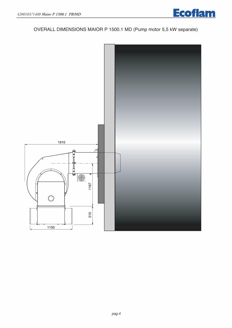
MODEL A B C D D1 E F G H I L MMaior P 1500.1 1550 800 750 590 - 1910 550 1167 510 620 620 M20
D = short head D1 = long head
Dimensions (mm)
pag.4
420010371400 Maior P 1500.1 PR/MD
OVERALL DIMENSIONS MAIOR P 1500.1 MD (Pump motor 4 kW separate)
1910
1167
510
1150
OVERALL DIMENSIONS MAIOR P 1500.1 MD (Pump motor 5,5 kW separate)

pag.5
420010371400 Maior P 1500.1 PR/MD
OVERALL DIMENSIONS MAIOR P 1500.1 MD (Pump motor 4 kW separate)
191011
67
SUNTECSUNTEC
510
1150
OVERALL DIMENSIONS MAIOR P 1500.1 MD (Pump motor 5,5 kW separate)

pag.6
420010371400 Maior P 1500.1 PR/MDH
YD
RAU
LIC
CIR
CU
IT
VL
A
31
2
M
Air
dam
per
R
VS
VS
1-
Hos
e 2
-O
il fil
ter
3-
Oil
cock
A-
Suct
ion
R-
Ret
urn
VL
-W
orki
ng o
il va
lve
VS
-Sa
fety
oil
valv
e
pag.7
420010371400 Maior P 1500.1 PR/MD
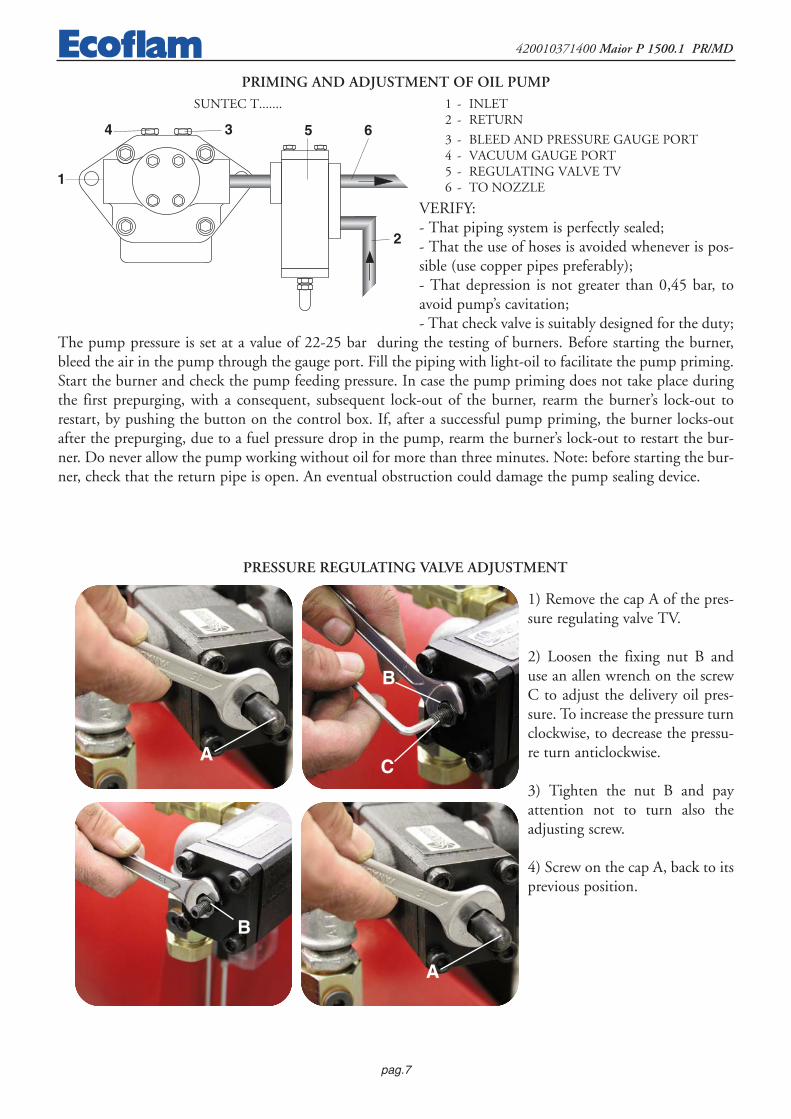
1) Remove the cap A of the pres-sure regulating valve TV.
2) Loosen the fixing nut B anduse an allen wrench on the screwC to adjust the delivery oil pres-sure. To increase the pressure turnclockwise, to decrease the pressu-re turn anticlockwise.
3) Tighten the nut B and payattention not to turn also theadjusting screw.
4) Screw on the cap A, back to itsprevious position.
SUNTEC T.......
PRIMING AND ADJUSTMENT OF OIL PUMP1 - INLET 2 - RETURN
3 - BLEED AND PRESSURE GAUGE PORT4 - VACUUM GAUGE PORT 5 - REGULATING VALVE TV6 - TO NOZZLE
VERIFY:- That piping system is perfectly sealed;- That the use of hoses is avoided whenever is pos-sible (use copper pipes preferably);- That depression is not greater than 0,45 bar, toavoid pump’s cavitation;- That check valve is suitably designed for the duty;
The pump pressure is set at a value of 22-25 bar during the testing of burners. Before starting the burner,bleed the air in the pump through the gauge port. Fill the piping with light-oil to facilitate the pump priming.Start the burner and check the pump feeding pressure. In case the pump priming does not take place duringthe first prepurging, with a consequent, subsequent lock-out of the burner, rearm the burner’s lock-out torestart, by pushing the button on the control box. If, after a successful pump priming, the burner locks-outafter the prepurging, due to a fuel pressure drop in the pump, rearm the burner’s lock-out to restart the bur-ner. Do never allow the pump working without oil for more than three minutes. Note: before starting the bur-ner, check that the return pipe is open. An eventual obstruction could damage the pump sealing device.
1
4 3 65
2
PRESSURE REGULATING VALVE ADJUSTMENT
A
B
C
B
A

pag.8
420010371400 Maior P 1500.1 PR/MD
TVVALVE
IDENTIFICATION
(Not all model combinations are availableConsult your Suntec representative)
TV : Pressure regulating valve
Pressure range :10 : 2 - 10 bars40 : 7 - 40 bars
TV 40 01 1
Regulation type :01 : by screw02 : by piston,
for modulating purpose
Revision number
This is a general specification leaflet ; for specific applicationsnot covered herein, contact Suntec.
The SUNTEC TV valve is a pressure regulating valve.
APPLICATIONS
- Light and heavy oil.- Capacity up to 5000 l/h.- May be used with the SUNTEC T pump.
VALVE OPERATING PRINCIPLE
The pressure of the nozzle line is adjusted with the adjusting screw of the TV valve.The oil in excess to nozzle requirement is dumped to the return.
To nozzle
To tank
Return Return tosuction
Oil under pressure
Oil under suction
By-passed oilreturned to tank,or to suction
TV - 11 - Ed 4 - June 99
TV VALVE
Intakefrom Tank
INSTALLATION
Two pipe system : oil in excess is returned to tank.
One pipe system : oil in excess is returned to pump suction.
Oil under pressure
By-passed oilIntake Return
To nozzle
Pressureadjustment
TVvalve T pump

pag.9
420010371400 Maior P 1500.1 PR/MD
167
197
45
45 43
52 75
60
TECHNICAL DATA
General
Connection threads Cylindrical according to ISO 228/1
Inlet G 3/4
Nozzle outlet G 3/4
Return G 3/4
Weight 3 kg
Intake or nozzle outlet
DIMENSIONS
We reserve the right to change specifications without prior notice.
Nozzle outlet or intake Return
TV - 11 - Ed 4 - June 99
Hydraulic data
Pressure ranges 10 : 2 - 10 bars(delivery pressure setting : 7 bars)
40 : 7 - 40 bars(delivery pressure setting : 20 bars)
Operating viscosity 4 - 450 cSt
Oil temperature 0 - 140°C max. in the valve.
MOUNTING POSITION
TV valve may be mounted in any position.
PRESSURE ADJUSTMENT
Remove cap-nut and washer , unscrew lock-nut .
To increase pressure, turn adjusting screw clockwise.
To decrease the pressure, turn screw anticlockwise.
Block lock-nut , refasten washer and cap-nut .
Washer
Adjustingscrew
Lock nut
Washer
Cap-nut

pag.10
420010371400 Maior P 1500.1 PR/MD

pag.11
420010371400 Maior P 1500.1 PR/MD

pag.12
420010371400 Maior P 1500.1 PR/MD
FLAME LENGTH LIGHT OIL BURNERS
FLAME DIAMETER LIGHT OIL BURNERS
4
5
6
0
2
3
kg/h
L (m)
200 300 400 500 600 700 800 900 1000 1100 1200
7
8
9
0,6
0,8
1
0
0,2
0,4
kg/h
Ø (m)
200 300 400 500 600 700 800 900 1000 1100 1200
1,2
1,4
1,6
1
1
2
2
1 - Stardard firing head 2 - Special firing head
pag.13
420010371400 Maior P 1500.1 PR/MDN
OZ
ZLE
: B
ER
GO
NZ
O T
YP
E C
150
0 kg
/h P
UM
P P
RE
SSU
RE
(25
bar
)
0200
400
600
800
1000
1200
1400
1600
46
810
1214
1618
2220
RE
TU
RN
PR
ESS
UR
E (
bar)
± 3
%
FLOW LIGHT OIL (kg/h) ± 3%
pag.14
420010371400 Maior P 1500.1 PR/MD
BURNER START-UP AND ADJUSTMENT
Once having installed the burner, check the following items:- The burner power feeding and the main line protection fuses- The correct length of pipes and that the same are sealed.- The type of fuel, which must be suitable for burner.- The connection of boiler’s thermostats and all the safeties.- The motor rotation direction.- The correct calibration of the motor’s thermal protection.When all the above mentioned conditions are checked and accomplished, it is possible to go on with bur-ner’s tests. Power the burner. The control box feeds the ignition transformer and the burner’s motor at thesame time, which will run a prepurging of the combustion chamber for about 20 sec.At the end of prepurging, the control box opens solenoid valves and the burner starts. After a safety intervalof 5 seconds and a correct ignition, the control box turns off the ignition transformer and, 10 seconds later,sets the motorised air damper to its maximum opening (High flame). In case of faulty ignition, the controlbox switches the burner into safety condition within 5 second. In such a case, the manual rearming of theburner shall not take place before 30 seconds have elapsed from the burner’s safety shutdown. In order toobtain an optimal combustion, it is necessary adjust the LOW - HIGH flame air flow, according to theinstruction given further on. During such a phase, it will be possible to manually switch between HIGH andLOW flame and viceversa, through the High/Low flame switch. At the end of the adjusting phase, leave theswitch in position AUTO.
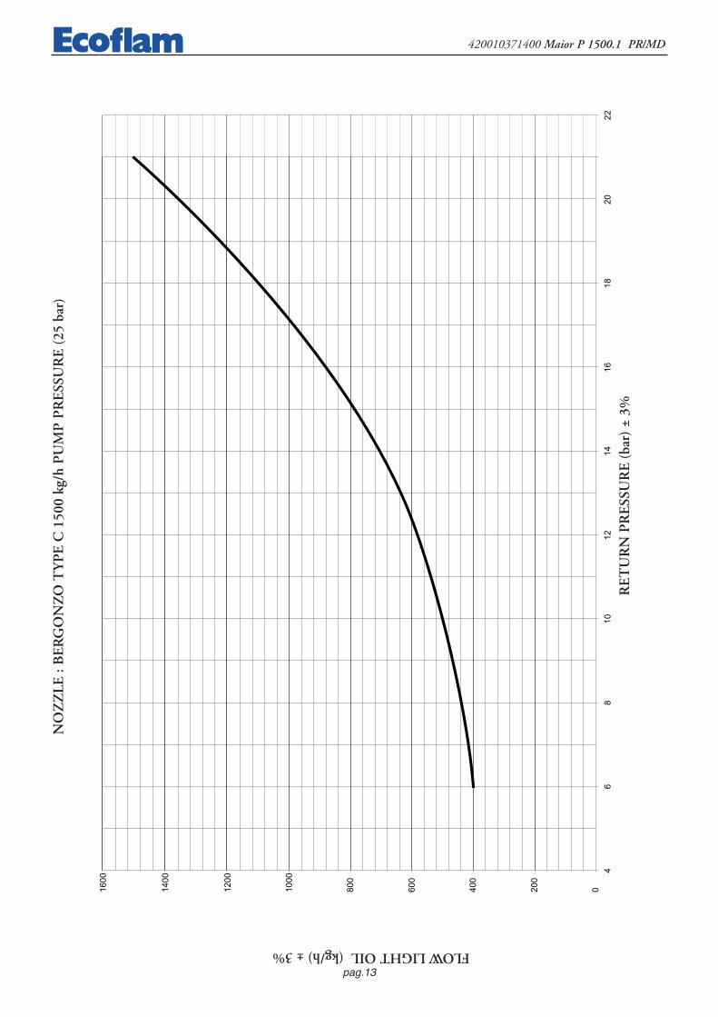
OIL DELIVERY ADJUSTMENTThe diagram illustrates the fuel feeding system of these types of burners, which incorpo-rates a by-pass nozzle with oil flow regulation on its return pipe. The oil supply isvaried by acting on the nozzle through the pressure in the return line. Max. oil supply istherefore reached when the pressure in the pump line is about 22 bar and the returnline is fully closed; min. oil supply when the return line is fully open. Relevantpressure readings in the return line are as follows:Pump pressure 22-25 bar.Max Burner output, return oil pressure:FLUIDICS nozzle : 16 ÷19 bar.BERGONZO nozzle : 20 ÷24 bar.Min Burner output, return oil pressure:FLUIDICS nozzle : 6 ÷9 barBERGONZO nozzle : 4 ÷8 bar
+-
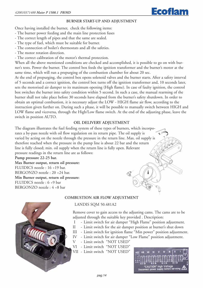
LANDIS SQM 50.481A2
Remove cover to gain access to the adjusting cams. The cams are to beadjusted through the suitable key provided . Description: I - Limit switch for air damper “High Flame” position adjustment.
II - Limit switch for the air damper position at burner’s shut downIII - Limit switch for ignition flame “Min power” position adjustment.IV - Limit switch for air damper “Low Flame” position adjustment.V - Limit switch “NOT USED”VI - Limit switch “NOT USED”VII - Limit switch “NOT USED”
COMBUSTION AIR FLOW ADJUSTMENT

pag.15
420010371400 Maior P 1500.1 PR/MD
VL
A
31
2
R
Air
dam
per
M
VS
VS
FIR
ING
HE
AD
MIN
PO
WE
R

pag.16
420010371400 Maior P 1500.1 PR/MDFI
RIN
G H
EA
D M
AX
PO
WE
R
VL
A
31
2
R
Air
dam
per
M
VS
VS

pag.17
420010371400 Maior P 1500.1 PR/MD
AIR ADJUSTMENT
+
--
Part. 1
Part. 2
Part. 3
-
+
-COMMUTATORE
0
AUTO
0 = bloccaggio degli apparati per il funzionamento in una posizione intermadia = funzionamento alla massima potenza = funzionamento alla minima potenza AUTO = funzionamento automatico
MINIMUM CAPACITY ADJUSTMENT OF THE BURNERPosition the selector, situated on the control panel, on position 2 and proceed as follows:Adjustment the minimum light oil flow rate (see figure, Nozzle diagram):
- using a suitable allen key, change the position of the cam guide blade; screwing the cam in, the light oil flow increases, while unscrewing it, it decrease.
Adjustment the minimum air flow rate (see figure, detail 1):- loosen the Allen screw on the air damper clamp;- turn the air damper until you reach the correct air flow, as established by analyzing
the combustion process.- tighten the Allen screw in place once again.
MAXIMUM CAPACITY ADJUSTMENT OF THE BURNERPosition the selector, situated on the control panel, on position 1 and proceed as follows:Adjustment the maximum light oil flow rate (see figure, Nozzle diagram):
- using a suitable allen key, change the position of the cam guide blade ; screwing the cam in, the light oilflow increases, while unscrewing it, it decrease.
Adjustment the maximum air flow rate (see figure, detail 2):- loosen the nut holding the air damper transmission rod;
ADJUSTMENT THE INTERMEDIATE BURNER CAPACITIESUsing the selector, start the servomotor (closing or opening) and position on 0 to stop the stroke; the adjust-ment is made as outlined below. Repeat the operation for the other cam points.Adjustment the intermediate light oil flow rates (see figure, detail 3):
- using a suitable Allen wrench, change the position of the cam guide blade; if you screw it down, the flow rate is reduced; if you unscrew it, the flow rate increases.
operating elements locked in an intermediate position
operation on maximum capacity operation on minimum capacity automatic operation
SELECTOR

pag.18
420010371400 Maior P 1500.1 PR/MD
NOZZLE CLEANING AND REPLACEMENTUse only the suitable box wrench provided for this operation to remove the nozzle, taking care to not dama-ge the electrodes. Fit the new nozzle with the same care.Note: Always check the position of electrodes after having replaced the nozzle (see illustration). A wrongposition could cause ignition troubles.
5÷6 mm
3÷4 mm
All burners are factory tested at 400V - 50Hz 3-phase for motors, and 230V - 50Hz single phase with neu-tral for auxiliary equipments. Should it be necessary to power the burner with 230V - 50Hz, modify theconnections on motor and the terminal board as shown in the picture. Protect the burner supply line withsuitable fuses and/or other safety devices as required by the local regulations on the matter.
ELECTRICAL CONNECTIONS
COMBUSTION ADJUSTMENT WARNING: In order to have a correct combustion and thermal output adjustments, these must be carriedout together with a combustion analysis, to be executed through suitable devices, taking care that the valuesare the correct ones and are in accordance with the local safety regulations. The adjustments must be carriedout by qualified and skilled technicians authorised by Ecoflam S.p.A..
SETTING THE FIRING HEAD

pag.19
420010371400 Maior P 1500.1 PR/MD
RWF 40 MICROPROCESSOR REGULATOR
Display:analog input 1(actual value)
Display: Set point SP1
Decrease value
Programming key
Manual operation
Auxiliary contact
Increase value
EXIT key.
Burner operation
Reduce powerCLOSE/1st Stage
Increase powerOPEN/2nd Stage
Two-stage operation
Description of display and keys on the RWF 40 microprocessor regulatorThe figure shows the normal display indicating
the actual value and the programmed setpoint, and equally important,
gives the meaning of thesingle keys and indicator Leds.
Configuration level
User Level
Normal display
Parameters level
PGM
PGM
PGM
PGM PGMPGM
PGM PGM
PGM PGM
min 2s
min 2s
min 2s
Exit
PROGRAMMING LEVELS

pag.20
420010371400 Maior P 1500.1 PR/MD
SETTING PARAMETERSWhen the burner is ignited all displays of the regulator light up. The set point display will blink for about 10 seconds. The valuein the upper field of the display (red) indicates the actual value. The value in the lower field of the display (green) indicates theset point currently programmed. CHANGING THE SET POINTTo change the set point, proceed as follows: -- Press the PGMPGM button to access the user level. SP1* will appear in the lower display-- Change the value of set point SP1 using the t and s keys.▼e ▲. -- After a 2 second delay the value set is stored automatically –To return to normal display press EXITEXIT. ** The value of SP1 depends on the value set previously in configuration level C111.SETTING PID PARAMETERSPID parameters are factory set to standard mean values. The operation of the regulator can be self-adapted to suit the system byactivating the “tunE” function. The regulator will set the PID parameters automatically. To activate the “tunE” function proceedas follows: -- With the burner in operation, press PGM PGM + ▼. -- the caption “tunE*” will blink in the display. – When “tunE”stops blinking, the self-adaptation routine has been completed. -- Confirm the computed parameters by pressing the ▲ key for 2seconds. ** The “tunE” function cannot be activated in Manual mode, or when the burner is off. The PID parameters can be corrected manually from the parameters level, working on the proportional band Pb1, the derivati-ve action time dt and the integral action time rt. To change parameters Pb1, dt and rt, proceeds as follows: -- Press the PGMPGM button to access the parameters level. -- To movefrom one parameter to the next, press PGMPGM . -- When Pb1 is displayed, the value can be increased or decreased using the s and tkeys. -- Confirm the changed parameters by pressing PGMPGM. -- If confirmation is not given within 2 seconds the value will be sto-red automatically. -- Press PGMPGM to access the next parameter. -- When dt is displayed, repeat the procedure described above. --Press PGM to access the next parameter. -- When rt is displayed, repeat the procedure above. -- To return to normal display pressEXITEXIT. DIFFERENTIAL SETTING FOR IGNITION AND SHUTOFFThe regulator allows the selection of an adjustable switching differential that establishes burner ignition and shutoff values.HYS1 indicates the lower ignition limit, below which the regulator switches the burner to maximum power. HYS3 indicatesthe upper shutoff limit, above which the regulator switches the burner off. To set HYS1 and HYS3 proceed as follows: -- Pressthe PGMPGM key to access the parameters level. -- To move from one parameter to the next, press PGMPGM . -- When HYS1 is displayed(burner ignition differential-stage II), increase or decrease the value using the ▼ and ▲ keys. -- Confirm the changed parametersby pressing PGMPGM. -- If confirmation is not given within 2 seconds the value will be stored automatically. -- Press PGMPGM to accessthe next parameter. -- When HYS2 is displayed (burner shutoff differential-stage II), repeat the procedure described above. -- PressPGMPGM to access the next parameter. -- When HYS3 is displayed (upper shutoff differential) repeat the procedure described above. -- To return to normal display press EXITEXIT.
MANUAL/AUTOMATIC MODETo access “MANUAL” mode, press and hold EXITEXIT for at least 5 seconds. Manual mode can only be selected when the burner isin operation. It is deactivated automatically when the burner shuts off. When the LED above the hand symbol is alight, theregulator is in manual mode and the position of the servocontrol can be changed using the ▼ and ▲ keys. The LEDS on thefront of the regulator indicate whether the servocontrol OPEN or CLOSE command is currently active. Pressing the ▼ key theservocontrol OPENS. Pressing the ▲ key the servocontrol CLOSES. To select automatic mode press and hold EXITEXIT for at least5 seconds. The LED above the hand symbol goes out and the regulator reverts to automatic.
CLIMATIC COMPENSATIONThe RWF 40 regulator can be set with the set point interlocked to the external probe. To select this operating mode, proceed asfollows: -- Connect the required probe as in the wiring diagram. -- Change the regulator settings. When using an external probethe regulator must be set as follows: -- Press the PGMPGM key to access the configuration level. When the caption C111 (XXXX) isdisplayed, use the ▲ key to access the second figure (XXXX). Use the ▼ key to select the type of probe (XX3X). -- Confirm thechange of parameters by pressing PGMPGM. If this is not done within 2 seconds, the value is stored automatically -- Press PGMPGM toaccess the configuration level. When the display reads C112 (XXXX), use the ▲ key to access the second figure (XXXX). Pressthe ▼ key to set the type of probe (XX3X). -- Confirm the changed parameters by pressing PGMPGM. -- If confirmation is not givenwithin 2 seconds the value will be stored automatically. -- To return to normal display press EXITEXIT. To establish the heating curve, proceed as follows: -- Press PGMPGM to access the parameters level. -- Press PGMPGM to move from one parameter to the next. -- When the letter H isdisplayed (heating curve gradient), increase or decrease the value using the ▼ and ▲ keys. -- Confirm the changed parameters bypressing PGMPGM. -- If confirmation is not given within 2 seconds the value will be stored automatically. -- To return to normal display press EXITEXIT.

pag.21
420010371400 Maior P 1500.1 PR/MD
PROBE CONNECTION DIAGRAMS
SPH
60
80
100
0
20
40
SPL
120
140
160
20 15 10 5 0 -20-15-10-517.5 12.5 7.5 2.5 -2.5 -17.5-12.5-7.5
0.20.40.60.811.21.41.61.822.22.42.62.833.23.43.63.84
External temperature (iC)
Hea
tin
g c
urv
e g
rad
ien
t (H
)
PARAMETERIZATION
Bo
iler
tem
per
atu
re s
et p
oin
t (i
C)
Cod.S704
Cod. S721Cod.S731
S731/1S731/2S731/3S731/4
Cod.S720/1
Connection for probeQAE2..(passive probe)Water probeConfiguration codeC111 = 9XXX
Connection for probeFT-TP/..(passive probe)(Degusa probe)Configuration codeC111 = 5XXX
Connection for probe QBE620-P..(active probes)Configuration code C111 = GXXXS731 - 0…4 bar / 0…400 kPa QBE620-P4 S731/1 - 0…10 bar / 0…1 MPa QBE620-P10 S731/2 - 0…16 bar / 0…1.6 Mpa QBE620-P16 S731/3 - 0…25 bar / 0…2.5 MPa QBE620-P25 S731/4 - 0…40 bar / 0…4 MPa QBE620-P40
Connection for probeQAC22 (passive probe)Configuration code C111 = XX3XC112 = XX1X
1 2 3 4
RWF 40
B M
G1+ M1
QAE22A
1 2 3 4
RWF 40
B M
B9 M9
QAC2..
1 2 3 4
RWF 40
GL M
G+ M1
OBE620-P..U1
G- U1
pag.22
420010371400 Maior P 1500.1 PR/MD
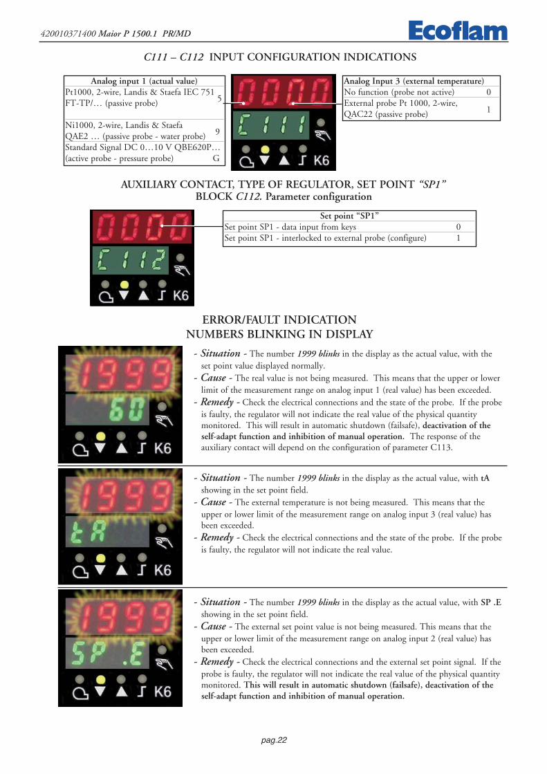
- Situation - The number 1999 blinks in the display as the actual value, with the set point value displayed normally.
- Cause - The real value is not being measured. This means that the upper or lowerlimit of the measurement range on analog input 1 (real value) has been exceeded.
- Remedy - Check the electrical connections and the state of the probe. If the probeis faulty, the regulator will not indicate the real value of the physical quantity monitored. This will result in automatic shutdown (failsafe), deactivation of theself-adapt function and inhibition of manual operation. The response of the auxiliary contact will depend on the configuration of parameter C113.
- Situation - The number 1999 blinks in the display as the actual value, with tAshowing in the set point field.
- Cause - The external temperature is not being measured. This means that theupper or lower limit of the measurement range on analog input 3 (real value) hasbeen exceeded.
- Remedy - Check the electrical connections and the state of the probe. If the probeis faulty, the regulator will not indicate the real value.
- Situation - The number 1999 blinks in the display as the actual value, with SP .Eshowing in the set point field.
- Cause - The external set point value is not being measured. This means that theupper or lower limit of the measurement range on analog input 2 (real value) hasbeen exceeded.
- Remedy - Check the electrical connections and the external set point signal. If theprobe is faulty, the regulator will not indicate the real value of the physical quantitymonitored. This will result in automatic shutdown (failsafe), deactivation of the self-adapt function and inhibition of manual operation.
ERROR/FAULT INDICATIONNUMBERS BLINKING IN DISPLAY
Analog input 1 (actual value)Pt1000, 2-wire, Landis & Staefa IEC 751
5FT-TP/… (passive probe)
Ni1000, 2-wire, Landis & Staefa9QAE2 … (passive probe - water probe)
Standard Signal DC 0…10 V QBE620P…(active probe - pressure probe) G
C111 – C112 INPUT CONFIGURATION INDICATIONS
Analog Input 3 (external temperature)No function (probe not active) 0External probe Pt 1000, 2-wire,
1QAC22 (passive probe)
AUXILIARY CONTACT, TYPE OF REGULATOR, SET POINT “SP1”BLOCK C112. Parameter configuration
Set point “SP1”Set point SP1 - data input from keys 0Set point SP1 - interlocked to external probe (configure) 1

pag.23
420010371400 Maior P 1500.1 PR/MD
TROUBLESHOOTINGThe burner does not start.- Main switch in “0”.- Fuses are blown.- Boiler thermostats are in open position.- Control box is defective.
The burner runs the prepurging but does not ignite and then switches into safety condition.- Control box is defective.- Ignition transformer is defective.- Electrodes are dirty.- Electrodes are defective.- Electrodes are in wrong position.- Nozzle are clogged.- Nozzle are too worn.- Filters are clogged.- Oil pressure too low.- Combustion air flow rate excessively high related to nozzle’s flow rate.
The burner ignites but then switches into safety condition.- Control box is defective.- Nozzle are clogged.- Nozzle are too worn.- The photocell does not detect the flame.- Filters are clogged.- Oil pressure too low.- Combustion air flow rate excessively high related to nozzle’s flow rate.
The burner does not switch to High flame .- Low flame and High flame stage manual switch on control board is in wrong position.- Control box is defective.- Oil pressure too low.- Filters are clogged.
A
Insert the RWF 40 regulator through the relative opening in the electrical panel (A). Insert the fixing anchors and screws into the slots, and secure the unit to the panel (B). To open the regulator, squeeze the cover from the ends as shown, and lift out (C).
WHEN REPLACEMENT IS NECESSARY, PROCEED AS SHOWN IN FIGURES A-B-C BELOW
B C

pag.24
420010371400 Maior P 1500.1 PR/MD
Parameter Display Ecoflam setting Ecoflam setting Ecoflam setting (passive probe) (passive probe) (active probe)
QAE22 FT-TP/1000 QBE620-P...Limit value of limit comparator AL 0 0 0Switching differential for limit comparator HYSt 0 0 0Proportional band Pb.1 8 8 1Derivative time dt 20 20 3Integral action time rt 80 80 15Dead band (neutral zone) db 0.5 0.5 0.5Actuator running time (sec.) tt 25 25 25Switch-on threshold burner / stage II HYS1 -2 -2 -0.2Switch-off level stage II HYS2 0 0 0Upper switch-off threshold HYS3 5 5 0.5Response threshold q 0 0 0Heating curve slope H 2 2 2Parallel displacement P 0 0 0
PARAMETERS
Parameter Display Ecoflam setting(passive probe) (active probe) QBE620-P...
QAE22 FT-TP/1000 -P4 -P10 -P16 -P25 -P40Analog input 1, 2 and 3; setpoint changeover / shift C111 9030 5030 G000 G000 G000 G000 G000Limit comparator; controller type; setpoint 1; locking C112 0010 0010 0010 0010 0010 0010 0010Unit address; decimal place / unit, signal for out-of-range C113 0110 0110 0110 0110 0110 0110 0110Measured value range start analog input 1 SCL 0 0 0 0 0 0 0Measured value range analog input 1 SCH 100 100 4 10 16 25 40Measured value range analog input 2 SCL2 0 0 0 0 0 0 0Measured value range analog input 2 SCH2 0 0 0 0 0 0 0Lower setpoint limit SPL 60 60 0 0 0 0 0Upper setpoint limit SPH 88 88 4 10 16 25 40Actual value correction,analog input 1 OFF1 0 0 0 0 0 0 0Actual value correction,analog input 2 OFF2 0 0 0 0 0 0 0Actual value correction,analog input 3 OFF3 0 0 0 0 0 0 0Filter time constant for digital filter, dF1 1 1 0 0 0 0 0analog input 1
CONFIGURATION

pag.25
420010371400 Maior P 1500.1 PR/MD
PAGI
NA D
I
3M
TP
S.p.A.
IND.
MO
DIFI
CA
SOST
.DA
SOST
.IL
IND.
MO
D.
PROPRIETA' RISERVATA DELLA DITTA ECOFLAM S.p.A.
DATA
-FIR
MA
DATA
FIRMA
CONT
ROLL
ATO
DESC
RIZI
ONE
MO
DIFI
CA
DISE
GNAT
O
DATA
FIRMA
COMUNICARE A TERZI IL CONTENUTO DEL PRESENTE. A TERMINE DI LEGGE E' VIETATO RIPRODURRE O
CONT
ROLL
O D
I TEN
UTA
APPA
RECC
HIAT
URA
UFF.T
ECNI
CO-S
ETTO
RE EL
ETTR
ICO
DENO
MIN
AZIO
NE
SIST
. RIV
ELAZ
.CO
DICE
MOT
ORI
DUTT
ORE
0001
0203
0405
0607
0809
A
0001
0203
0405
0607
0809
B C D E
A B C D E
4038
39
AB
C
ASZ..
.1/2
4241
3637
S1
MP
UV
W
1311
12
SPA
2827
29N
N
YVgR
YVgA
32N
3031
W1
U1
V1V2
U2
W2
3534
33
2717
76
525
1624
1514
426
32
2213
2112
111
1 NM
YVgC
-UB
TV
LAND
IS SQ
M 50
.481A
2
23
BEM
3002
9M
AIO
R P
1500
.1 M
DLA
NDIS
SQ
M 5
0.48
1A2
B29
-06-
2007
BEM
3002
1
V2U
2W
2
3M
MV
W1
V1U
1

pag.26
420010371400 Maior P 1500.1 PR/MD
IND.
MO
DIFI
CA
SOST
.DA
SOST
.IL
IND.
MO
D.
PROPRIETA' RISERVATA DELLA DITTA ECOFLAM S.p.A.
DATA
-FIR
MA
DATA
FIRMA
CONT
ROLL
ATO
DESC
RIZI
ONE
MO
DIFI
CA
DISE
GNAT
O
DATA
FIRMA
COMUNICARE A TERZI IL CONTENUTO DEL PRESENTE. A TERMINE DI LEGGE E' VIETATO RIPRODURRE O
CONT
ROLL
O D
I TEN
UTA
APPA
RECC
HIAT
URA
UFF.T
ECNI
CO-S
ETTO
RE EL
ETTR
ICO
DENO
MIN
AZIO
NE
SIST
. RIV
ELAZ
.CO
DICE
MOT
ORI
DUTT
ORE
TRAN
SFOR
MAT
EUR
D'AL
LUM
AGE
MOT
OR V
ENTI
LADO
R
TRAN
SFOR
MAD
OR
IGNI
TION
TRAN
SFOR
MER
TRAS
FORM
ATOR
ETV
MUT
EUR
VENT
ILATE
URM
OTOR
FAN
MOT
ORE V
ENTI
LATO
REM
V
YVgC
-UOI
L SHU
T-OF
F SOL
ENOI
DSO
LENO
IDE C
HIUS
URA
UGEL
LO
FOTO
RESI
STEN
CIA
PHOT
ORES
ISTA
NCE
PHOT
O-RE
SIST
ORFO
TORE
SIST
ENZA
B
PAGI
NA D
I
YVgA
ELET
TROV
ALVO
LA D
I AND
ATA
ELET
TROV
ALVO
LA D
I RITO
RNO
YVgR
MP
FLOW
SOLE
NOID
VALV
E
RETU
RN SO
LENO
ID VA
LVE
MOT
ORE P
OMPA
OIL P
UMP
MOT
ORM
OTEU
R PO
MPE
MOT
OR B
OMBA
S1FI
NECO
RSA
LIMIT
SWITC
HIN
TERR
UPTE
UR D
E FIN
DE C
OURS
ELIM
ITADO
R DE
CAR
RERA
0001
0203
0405
0607
0809
A
0001
0203
0405
0607
0809
B C D E
A B C D E
S.p.A.
CAM
MA
DI R
EGOL
AZIO
NE A
RIA
ALTA
FIAM
MA
LAVO
RO
CAM
MA
DI R
EGOL
AZIO
NE A
RIA
BASS
A FI
AMM
A LA
VORO
CA
MM
A RE
GOLA
ZION
E ARI
A AC
CENS
IONE
MIN
IMA
POTE
NZA
NON
UTILI
ZZAT
AV
II:
NON
UTILI
ZZAT
ANO
N UT
ILIZZ
ATA
CAM
MA
REGO
LAZI
ONE A
RIA
CHIU
SURA
TOTA
LE
III:
IV:
V: VI:
I: II:
BEM
3002
9M
AIO
R P
1500
.1 M
DLA
NDIS
SQ
M 5
0.38
1A2
LAND
IS L
AL 1
.25
UV29
-06-
2007
BEM
3002
1
00
00
0
LAND
IS SQ
M 50
.381A
2 2412
N
I
111
21
M1
IIIII
IV
222
13
VVI
VII
1423
34
17
VIII15
525
166
2627
7
2/2

pag.27
420010371400 Maior P 1500.1 PR/MD
PAGI
NA D
I
LINE
LOAD
QAC2
...MB
QAE2
..
MB
QBE6
20-P
GLM
U1
S.p.A.
IND.
MO
DIFI
CA
SOST
.DA
SOST
.IL
IND.
MO
D.
PROPRIETA' RISERVATA DELLA DITTA ECOFLAM S.p.A.
DATA
-FIR
MA
DATA
FIRMA
CONT
ROLL
ATO
DESC
RIZI
ONE
MO
DIFI
CA
DISE
GNAT
O
DATA
FIRMA
COMUNICARE A TERZI IL CONTENUTO DEL PRESENTE. A TERMINE DI LEGGE E' VIETATO RIPRODURRE O
CONT
ROLL
O D
I TEN
UTA
APPA
RECC
HIAT
URA
UFF.T
ECNI
CO-S
ETTO
RE EL
ETTR
ICO
DENO
MIN
AZIO
NE
SIST
. RIV
ELAZ
.CO
DICE
MOT
ORI
DUTT
ORE
0001
0203
0405
0607
0809
A
0001
0203
0405
0607
0809
B C D E
A B C D E
4038
3942
4136
37
FMP95 96
22
3534
33
RESE
T
2526
2728
2930
3132
HLF
43
12
1312
1124
N
FMP
KMP
W2
V2U
2V1
W1
U1
HLB
1/2
3132
2422
2321
1920
1617
18
KASA
MA 1
23
0
1314
1110
129
87
54
62
13
HLF
FMV95 96
FMV
97 98
Z
FU SAL
KTav
vH
LBT
LAND
IS LA
L 1.25
15
2123
2419
1820
SE
SWIT
CH M
ANUA
L-AU
TOM
ATIC
SP
COM
MUT
ATO
RE M
ANUA
LE-A
UTO
MAT
ICO
CONM
UTAD
OR
MAN
UAL-
AUTO
MAT
ICO
INTE
RRRU
PTEU
R M
ANUE
L-AU
TOM
ATIQ
UE
QA
E2...
, FT-
TP/..
.CO
LLEG
AM
ENTO
SO
ND
A P
ASS
IVA
REG
OLA
TORE
RW
F 40
COLL
EGA
MEN
TI A
L
R S
PE
NT
LAN
DIS
RW
F 40
SAM
A
12
30
2321
2022
1816
1517
19
HLB
PT
STC
PT
STS
SA
NR
ST
Q
14
50 H
z 400
V
pos 0
: ARR
ESTO
/ ST
OP
pos 2
: BAS
SA F
IAM
MA/
LOW
FLA
ME/
1e A
LLUR
E/BA
JA L
LAM
A
pos 1
: ALT
A FI
AMM
A/HI
GH F
LAM
E/2e
ALL
URE/
ALTA
LLA
MA
pos 3
: AUT
OM
ATIC
O/A
UTO
MAT
IC/A
UTO
MAT
IQUE
INTE
RNA
QU
AD
ROM
ORS
ETTI
ERA
M1L
NQ
Q14
Y2Y1
Q13
G+G-
B9U1
G1+
M9
KMV2
KMV1
KMV3
KMV3
KMV1
KMV2
KMV1
FMV
BEM
3003
0M
AIO
R P
1500
.1 M
DLA
NDIS
SQ
M 5
0.48
1A2
LAND
IS L
AL 1
.25
B29
-06-
2007
BEM
3002
0

pag.28
420010371400 Maior P 1500.1 PR/MD
RELE
' TER
MIC
O M
OTOR
BOM
BARE
LAIS
THER
MIQ
UE M
OTEU
R PO
MPE
MOT
OR P
UMP
THER
MAL
REL
AYRE
LE' T
ERM
ICO
MOT
ORE P
OMPA
FMP
STC
SAL
WOR
KING
SWITC
HIN
TERR
UTTO
RE D
I LIN
EA
INTE
RRUP
TEUR
DE L
IGNE
INTE
RRUP
TOR
DE LI
NEA
TERM
OSTA
TO C
ALDA
IABO
ILER
THER
MOS
TAT
THER
MOS
TAT C
HAUD
IERE
TERM
OSTA
TO C
ALDE
RA
PAGI
NA D
I
TERM
OSTA
TO D
I SIC
UREZ
ZASA
FETY
THER
MOS
TAT
THER
MOS
TAT D
E SEC
URIT
ETE
RMOS
TATO
DE S
EGUR
IDAD
LAM
PADA
DI B
LOCC
O TE
RMIC
O
COM
MUT
ATOR
E MAN
UALE
-AUT
OMAT
ICO
THER
MAL
LOCK
-OUT
LAM
PLA
MPE
DE T
HERM
AL D
E SEC
URIT
EES
PIA
DE B
LOQU
EO R
ELE T
ERM
ICO
SWITC
H (M
ANUA
L-AU
TOM
ATIC
))IN
TERR
UPTE
UR M
ANUE
L-AU
TOM
ATIQ
UECO
NMUT
ADOR
MAN
UAL-
AUTO
MAT
ICO
STS
HLBT
SAM
AQ
FUSI
BILE
FUZFI
LTRO
ANT
IDIS
TURB
O
MAI
N SW
ITCH
WIT
H FU
SE
ANTJ
AMM
ING
FILT
ERFI
LTRE
ANT
IPARA
SITE
S
INTE
RRUT
TORE
GEN
ERAL
E CON
FUSI
BILE
INTE
RRUP
TEUR
GEN
ERAL
AVE
C FU
SIBL
EIN
TERR
UPTO
R GE
NERA
L CON
FUSI
BLE
FILT
RO D
E PRO
TECI
ON A
NTID
ISTU
RBIO
TEM
PORI
ZZAT
ORE E
LETT
.AVV
. STE
LLA/
TRIN
AGOL
OEL
ECTR
ONIC
TIM
ER W
ITH
STAR
/DEL
TA ST
ARTE
RTE
MPO
RIZA
DOR
EL…
CTRO
NICO
PRE
PARA
DO PA
RATE
MPO
RIZA
DOR
EL…
CTRO
NICO
PRE
PARA
DO PA
RA
KTav
v.
RELE
'
FUSI
BLE
FUSI
BLE
RELA
YKA
RELE
'RE
LAIS
FMV
RELE
' TER
MIC
O M
OTOR
E VEN
TILA
TORE
MOT
OR TH
ERM
AL R
ELAY
(FAN
MOT
OR)
RELA
IS TH
ERM
IQUE
MOT
EUR
VENT
ILATE
URRE
LE' T
ERM
ICO
MOT
OR V
ENTI
LADO
R
HLF
KMV1
WOR
KING
LAM
PLA
MPE
DE F
ONCT
IONN
EMEN
TES
PIA
DE FU
NCIO
NAM
IENT
O
LOCK
-OUT
LAM
PLA
MPE
DE S
ECUR
ITE
ESPI
A DE
BLO
QUEO
KMV2
KMV3
CONT
ATTO
RE M
OTOR
E VEN
TILA
TORE
LAM
PADA
DI F
UNZI
ONAM
ENTO
CONT
ATTO
RE M
OTOR
E VEN
TILA
TORE
CONT
ATTO
RE M
OTOR
E VEN
TILA
TORE
REM
OTE C
ONTR
OL SW
ITCH
(FAN
MOT
OR)
CONT
ACTE
UR M
OTEU
R VE
NTILA
TEUR
TELE
RRUP
TOR
MOT
OR V
ENTI
LATO
R
REM
OTE C
ONTR
OL SW
ITCH
(FAN
MOT
OR)
CONT
ACTE
UR M
OTEU
R VE
NTILA
TEUR
TELE
RRUP
TOR
MOT
OR V
ENTI
LATO
R
REM
OTE C
ONTR
OL SW
ITCH
(FAN
MOT
OR)
CONT
ACTE
UR M
OTEU
R VE
NTILA
TEUR
TELE
RRUP
TOR
MOT
OR V
ENTI
LATO
R
LAM
PADA
DI B
LOCC
OHL
B
IND.
MO
DIFI
CA
SOST
.DA
SOST
.IL
IND.
MO
D.
PROPRIETA' RISERVATA DELLA DITTA ECOFLAM S.p.A.
DATA
-FIR
MA
DATA
FIRMA
CONT
ROLL
ATO
DESC
RIZI
ONE
MO
DIFI
CA
DISE
GNAT
O
DATA
FIRMA
COMUNICARE A TERZI IL CONTENUTO DEL PRESENTE. A TERMINE DI LEGGE E' VIETATO RIPRODURRE O
CONT
ROLL
O D
I TEN
UTA
APPA
RECC
HIAT
URA
UFF.T
ECNI
CO-S
ETTO
RE EL
ETTR
ICO
DENO
MIN
AZIO
NE
SIST
. RIV
ELAZ
.CO
DICE
MOT
ORI
DUTT
ORE
FUSE
II:I: VI:
V:IV:
III:
CAM
MA
REGO
LAZI
ONE A
RIA
CHIU
SURA
TOTA
LE
NON
UTILI
ZZAT
ANO
N UT
ILIZZ
ATA
VII:
NON
UTILI
ZZAT
A
CAM
MA
REGO
LAZI
ONE A
RIA
ACCE
NSIO
NE M
INIM
A PO
TENZ
A CA
MM
A DI
REG
OLAZ
IONE
ARI
A BA
SSA
FIAM
MA
LAVO
RO
CAM
MA
DI R
EGOL
AZIO
NE A
RIA
ALTA
FIAM
MA
LAVO
RO
S.p.A.
0001
0203
0405
0607
0809
A
0001
0203
0405
0607
0809
B C D E
A B C D E
2/2
727
266
1625
515 VIII
174
323
14
VII
VIV
132
22
IVII
III
1M
211
11
I
N12
24
LAND
IS SQ
M 50
.481A
2
00
00
0
BEM
3003
0M
AIO
R P
1500
.1 M
DLA
NDIS
SQ
M 5
0.48
1A2
LAND
IS L
AL 1
.25
UV29
-06-
2007
BEM
3002
0

pag.29
420010371400 Maior P 1500.1 PR/MD
MA
IOR
P 1
500.
1 P
R/M
D
FIND
ER
FIND
FIND
ER
PG
ME
XIT
3132
33
343536
37
40
4142
4351
44
45
1427
65
7
4
29
52
30
11
109
8
47
531312
38
39
46
505960
54
355
56
5758
49
12

pag.30
420010371400 Maior P 1500.1 PR/MD
MAIOR 1500.1 PR/MDN° DESCRIPTION code
1 PUMP SUNTEC T5C105 653229982 OIL VALVE SUNTEC TV40011 653229953 UNION 653217914 AIR PRESSURE SWITCH DUNGS LGW10 A2P 653230475 GLASS 653204876 PEED WINDOM FRAME 653204887 MOTOR 45 kW 653249338 FAN 653249349 AIR CONVEYOR 6532446510 CONVEYOR RING 6532446611 AIR INTAKE 6532446712 CONTROL BOX BASE LANDIS 6532009713 CONTROL BOX LANDIS LAL1.25 TV22" 6532005214 IGNITION TRANSFORMER BRAHMA T8 6532322215 REMOTE CONTROL SWITCH -16 REMOTE CONTROL SWITCH -17 MOTOR THERMAL RELAY -18 TIMER -19 MAIN SWITCH -20 RESET BUTTON -21 SELECTOR -22 LAMP -23 FUSE SUPPORT -24 RELE BASE -25 RELE -26 TIMER -27 PHOTORESISTOR Landis QRB1A-A050B70A 6532007628 ANTIJAMMING FILTER -29 IGNITION CABLE 6532094630 IGNITION ELECTRODES SET 6532216531 COIL EL011 6532380932 CONNECTOR WITH RECTIFIER 6532357133 COIL SUPPORT RING 6532172134 FIRING HEAD SUPPORT 6532508835 SPRING SUPPORT 6532172036 FIRING HEAD 6532467337 HEAD SLIDING PIPE 6532426738 FIRING HEAD ADJUSTMENT SUPPORT 6532508939 FIRING HEAD ADJUSTMENT 6532447040 ROD 6532426941 DIFFUSER SUPPORT 6532069742 NOZZLE HOLDER 6532467543 DIFFUSER 6532509044 INNER ASSEMBLY45 BLAST TUBE 6532447746 AIR DAMPER MOTOR LANDIS SQM50.481A2 6532290247 SILENCER 6532453748 OIL FILTER -49 HOSES -50 MANOMETER CEWAL R1/4 D50-40BAR 6532410551 NOZZLE BERGONZO kg/h 1500 6532509152 GASKET 6532447853 MODULATING UNIT LANDIS RWF 40 6532204454 PUMP MOTOR 5,5 kW 6532433755 COUPLING (MOTOR) 6532447956 COUPLING (PUMP) 6532436457 OIL VALVE LUCIFER 121 6532509258 COIL LUCIFER59 OIL VALVE LUCIFER 1/2 E321H25 6532363360 COIL LUCIFER

pag.31
420010371400 Maior P 1500.1 PR/MD

ECOFLAM BRUCIATORI S.p.A. reserves the right to make any adjustments, without prior notice, which it considersnecessary or useful to its products, without affecting their main features.
Ecoflam Bruciatori S.p.A. via Roma, 64 - 31023 RESANA (TV) - Italy - tel. 0423.719500 - fax 0423.719580 http://www.ecoflam-burners.com - e-mail: [email protected]
"società soggetta alla direzione e al coordinamento della Ariston Thermo S.p.A., via A. Merloni, 45 - 60044 Fabriano (An) CF 01026940427"