use of surface electromyography to control an …
TRANSCRIPT
USE OF SURFACE ELECTROMYOGRAPHY TO CONTROL AN ACTIVE
UPPER LIMB EXOSKELETON ACTUATED BY PNEUMATIC
ARTIFICIAL MUSCLES AND OPTIMIZED WITH GENETIC
ALGORITHMS João Luiz Almeida de Souza Ramos
Marco Antônio MeggiolaroPontifical Catholic University of Rio de Janeiro Department of Mechanical Engineering Rua Marquês de São Vicente 225, Gávea Rio de Janeiro, RJ – 22543-900 [email protected] [email protected]
Abstract. Robotics for rehabilitation and human amplification is imminent to become part of our daily life. The juxtaposition of human control capability and machine mechanical power offers a promising solution for human assistance and force enhancement. This paper presents an alternative and simple exoskeleton and a Human-Machine Interface (HMI) for human strength and endurance amplification using a version of the Hill-type muscle model. Pneumatic Artificial Muscles (PAM) are used as actuators for its high power-to-weight ratio. Genetic Algorithms (GA) approach locally optimizes the control model parameters for the assistive device using muscle surface electromyography (sEMG). The proposed methodology offers three main advantages: (i) it reduces the number of electrodes needed to monitor the muscles, (ii) it eliminates the need for user force sensing, and (iii) it reduces the real-time processing effort which is necessary for embedded implementation and portability due to the decreased complexity of the instrumentation system.
Keywords: Exoskeleton, Electromyography, Human Amplification, Genetic Algorithms, Pneumatic Muscles
1. INTRODUCTION
Lack of flexibility and adaptation are two of the main drawbacks of control algorithms for assistive devices when compared to human natural control capability. Man and machine integration combines human complex control with mechanical power, thus becoming very promising for human amplification.
The greatest challenge of uniting these two entities relies on developing a Human-Machine Interface (HMI) that can control the amplification device with the same naturalness and smoothness of the user movements. Many approaches with different physical quantities can be used including electromyography (EMG), electroencephalography (EEG), haptics, voice, vision, or some combinations of these (Ormiga, 2010). The difficulty of using this type of bio-signals as continuous control commands is the nonlinear and the nonstationary characteristics – in particular the EMG and EEG - they provide (Rash, 2003; De Luca, 1993; and Konrad, 2005). Past studies (Fleisher, 2007; Rose et al., 1998; Lloyd and Besier, 2002; Au et al., 2005; Shau et al., 2009; Luh et al., 1998; Ullah et al., 2011; Gopura and Kiguchi, 2009; and Cavallaro et al., 2006) developed models to extract the desired information from these biological control variables, including black-box methods, such as Artificial Neural Networks (ANN), and mathematical models such as the Hill-type Muscle Model used in this work.
The present work proposes a different methodology for estimating the torque on the exoskeleton joint using the processed and filtered muscular surface electromyography (sEMG). It makes an approximation to the torque exerted by the user scaled with a nonlinear gain factor and uses that signal as control input for the wearable robot. The 11kg Naval Aluminum exoskeleton performs the task of lifting a payload, while smoothly actuated by pneumatic artificial muscles (PAM) - which have an excellent power-to-weight ratio. The validation methodology adopted by this study is done by comparing the neural activation level with and without the assistive device during static and dynamic trials.
The HMIs developed so far usually demand a direct force feedback from the user or rather a very precise dynamic model of the exoskeleton in order to decrease its disturbance of the user movements (Gopura and Kiguchi, 2009). Muscle natural signals are beneficial for anticipating these movements due to the electromechanical delay (EMD) from neural activation to muscle contraction (Rosen et al., 1998).
This paper is organized in seven sections. Section 2 concerns the mechanical design of the exoskeleton that was used as a testbed, including the PAM model. Section 3 explains the Hill muscle model used to process the bio-signals and to estimate the control torque. Section 4 shows the parameter optimization methodology using Genetic Algorithms (GA) and their calibration for different sessions. Section 5 regards the control of the exoskeleton and the test procedure while section 6 shows the experimental results. Finally, section 7 discusses the conclusions of this work and suggests future possibilities.
ABCM Symposium Series in Mechatronics - Vol. 6 Copyright © 2014 by ABCM
Part I - International Congress Section VI - Hydraulics & Pneumatics
757
2. MECHANICAL DESIGN OF THE EXOSKELETON
The goal of the exoskeleton is to complete the task of lifting a payload. The mechanical design chosen to reducethe degrees of freedom (DOF) to complete the task was selected as the simplest as possible. The proposed design has only three DOF, two of which are active. To lift a payload the shoulder and elbow flexion/extension are required; flexion actuation assistance is mandatory, while gravity is responsible for extension.
Moreover, as the exoskeleton is directly connected to the user, it is necessary to guarantee anthropomorphism and smoothness. A human upper limb joint is capable of reaching a wide range of movement; however, it can develop limited torques (Gopura and Kiguchi, 2009), demanding powerful and light actuators. The solution proposes the use of artificial fluidic muscles to drive the system, due to the fact that it has a high power-to-weight ratio, 1-1.5kW/kg compared to 50-100W/kg of electric actuators and 100-200W/kg of pneumatic and hydraulic ones (Szepe, 2010). PAMs are less likely to leak, and can be very smoothly actuated.
2.1 The Pneumatic Artificial Muscle (PAM)
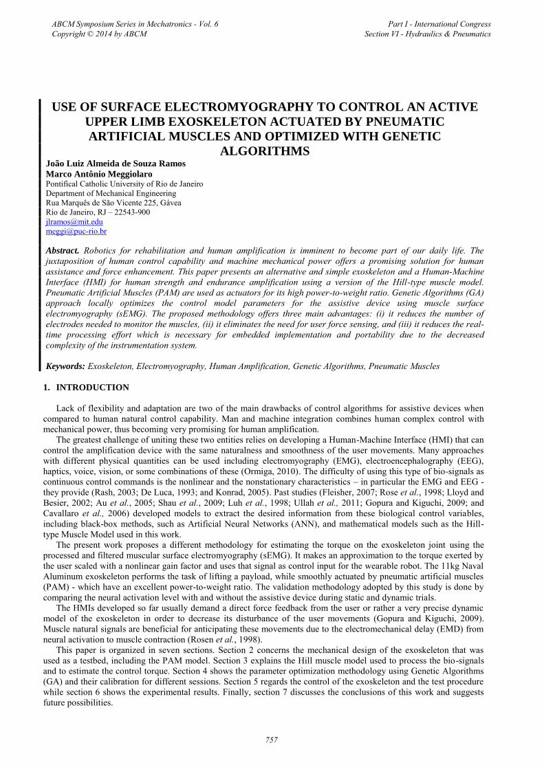
The PAM is composed of a rubber bladder with an inner fiber cloth (Szepe, 2010). When air is pressurized it contracts axially and expands radially (see Fig. 1), acting like a simple action cylinder. It can also be modeled as a nonlinear spring with a pressure-controlled stiffness.
Figure 1. Festo® PAM MAS-10 pressurization
The PAM inherent compliance is useful for safety reasons while protecting the user from high jerk movements but its nonlinearity is difficult to model and demands a complex controller. The force it delivers is proportional to the inner pressure P, relative contraction h and contraction ratio dh/dt (FESTO Catalogue, 2010). To determine the pressure needed to maintain a certain force F given the current contraction, (Szepe, 2010) suggests a static model of the PAM, with the force given by
.1exp, 5432
10 pPphpph
pPphPF
(1)
The exponential function is the best candidate to fit the high variation that can be evidenced on its behavior. In Eq. (1), pi (i = 0,1..5) are unknown parameters that need to be calibrated. This function F(P,h) is invertible and we obtain an analytical closed formula for the pressure PF in the muscle:
.1exp
1exp,
432
0
52
1
phpph
p
Fpph
phFP
(2)
2.2 Determining the PAM
Human upper limb is capable of developing limited torques while reaching a wide workspace. Although fluidic muscle can be very light and yet powerful, the main disadvantage is the low contraction capacity – approximately 20% of its nominal length at the maximum allowed pressure (8 bar for the MAS-10). Hence, the PAM required to achieve such range-to-load tradeoff is impractically long to be mounted directly over the arm link, which varies from 300-400mm.
To address that problem, we adopted a cable-driven transmission system which places the PAMs in a rear backpack enclosure, allowing these actuators to have a longer extension, such as (Kobayashi et al., 2009). The transmission
ABCM Symposium Series in Mechatronics - Vol. 6 Copyright © 2014 by ABCM
Part I - International Congress Section VI - Hydraulics & Pneumatics
758
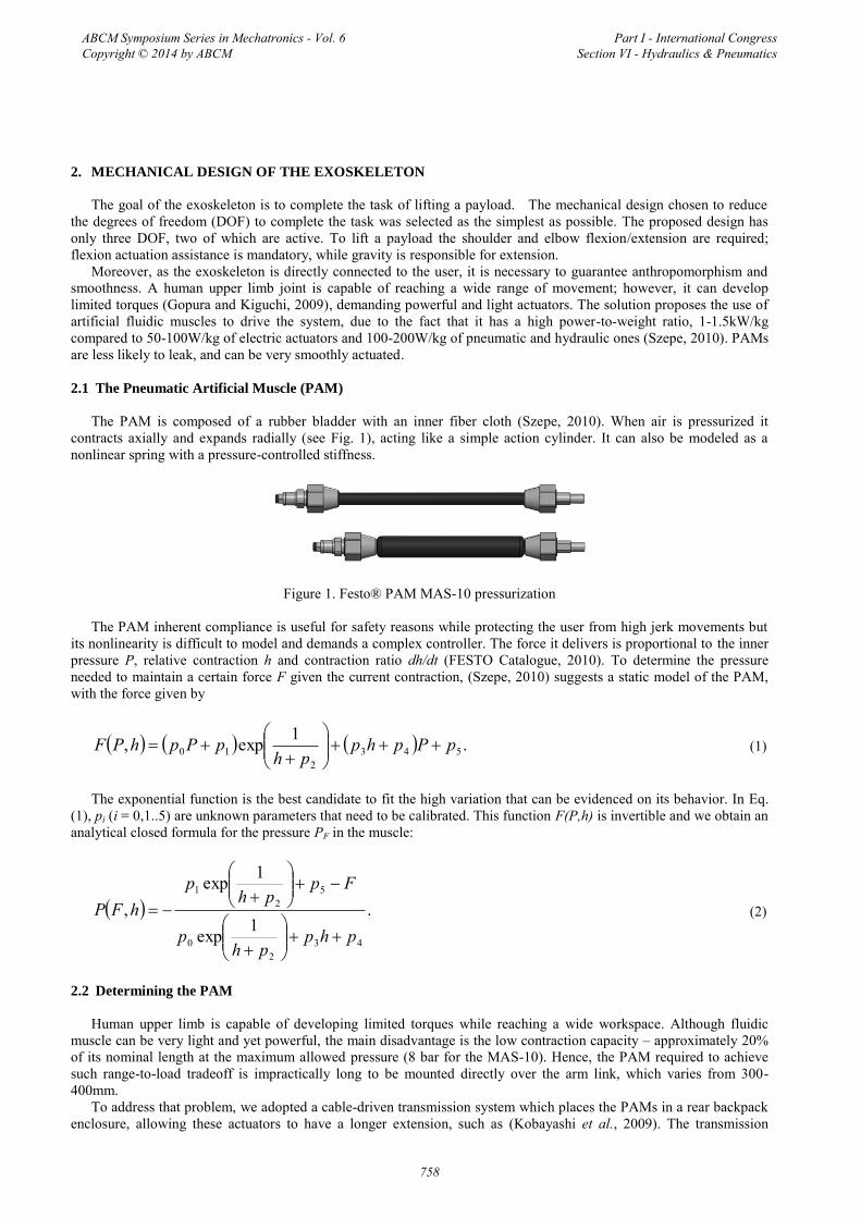
system consists of a steel cable that slides inside steel tubes with an inner Teflon coat to reduce friction, the same as parking brake cables. To increase the torque capacity, three PAMs were to actuate each joint, see Fig. 2.
Figure 2. The DOF of the exoskeleton (left); and the final SolidWorks CAD (right)
The entire exoskeleton is made out of Naval Aluminum weighting a total of 11kg (24,3lb).
3. THE HILL MUSCLE MODEL
3.1 Muscle Force Estimation
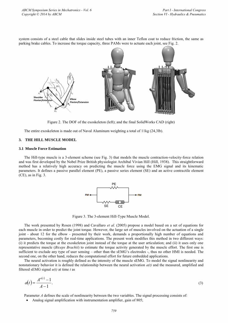
The Hill-type muscle is a 3-element scheme (see Fig. 3) that models the muscle contraction-velocity-force relation and was first developed by the Nobel Prize British physiologist Archibal Vivian Hill (Hill, 1938). This straightforward method has a relatively high accuracy on predicting the muscle force using the EMG signal and its kinematic parameters. It defines a passive parallel element (PE), a passive series element (SE) and an active contractile element (CE), as in Fig. 3.
Figure 3. The 3-element Hill-Type Muscle Model.
The work presented by Rosen (1998) and Cavallaro et al. (2005) propose a model based on a set of equations for each muscle in order to predict the joint torque. However, the large set of muscles involved on the actuation of a single joint - about 12 for the elbow - presented by their work, demands a proportionally high number of equations and parameters, becoming costly for real-time applications. The present work modifies this method in two different ways: (i) it predicts the torque at the exoskeleton joint instead of the torque at the user articulation; and (ii) it uses only one representative muscle (Biceps Brachii) to estimate the torque activity generated by the muscle effort. The first one is sufficient to exclude any type of user sensing – other than the sEMG‘s electrodes -, thus no other HMI is needed. The second one, on the other hand, reduces the computational effort for future embedded applications.
The neural activation is roughly defined as the intensity of the muscle sEMG. To model the signal nonlinearity and nonstationary behavior it is defined the relationship between the neural activation a(t) and the measured, amplified and filtered sEMG signal u(t) at time t as
.1
1
AAta
tu
(3)
Parameter A defines the scale of nonlinearity between the two variables. The signal processing consists of: Analog signal amplification with instrumentation amplifier, gain of 805;
ABCM Symposium Series in Mechatronics - Vol. 6 Copyright © 2014 by ABCM
Part I - International Congress Section VI - Hydraulics & Pneumatics
759
Second-order Butterworth high-pass digital filter with 20Hz cut-off frequency; Digital full wave rectification; Second-order Butterworth low-pass digital filter with 6Hz cut-off frequency.
The first filter excludes the motion artifact due to skin impedance changes when it stretches and the third filter returns the envelope of the rectified signal. From Fig. 3 we can extract three relations between the model parameters: (i) parallel elements share the same displacement,
;SECEPE LLL (4)
(ii) series elements share the same force,
;CESE FF (5)
and (iii) the total force developed by the muscle is given by the sum of the forces on the parallel elements,
.PESEPECEM FFFFF (6)
According to this model, the force (FPE,SE) exerted by the passive parallel and series elements is given by:
,1exp
1 max
max,
LtLS
eFF SSEPE (7)
where Fmax is the maximal force made by each element, S is a shape parameter related to the muscle stiffness, and ΔL(t) and ΔLmax are the current and maximal contraction, respectively.
On the other hand, the active force made by the contractile element,
,maxCEvlCE FfftaF (8)
is a function of the neural activation a(t) and the normalized force-length fl are given empirically by
.5.0exp
2
0
v
mCE
CE
lL
tL
f
(9)
It is modeled as a Gaussian function with mean value regulated using φm and φv. The normalized force-velocity fv is taken as
.64.18.2sinh3.1exp1074.0
1433.0
0
tVtV
f
CE
CEv (10)
In Eq. (8), FCEmax is the maximal force that can be generated by the contractile element, and LCE0 is defined as the optimal fiber length, i.e., the position where the muscle can develop the greatest force possible. Furthermore, ΔLCE(t) is the relative contraction, and VCE(t) the instantaneous contraction velocity. Moreover, VCE0(t) can be derived as a function of the neural activation a(t) and the maximal velocity VCEmax:
,15.0 max0 CECE VtatV (11)
where
ABCM Symposium Series in Mechatronics - Vol. 6 Copyright © 2014 by ABCM
Part I - International Congress Section VI - Hydraulics & Pneumatics
760
.412 0max CECE LV (12)
Other useful relations are
,05.0 maxmax CEPE FF (13)
,0max TsCEPE LLLL (14)
,3.1 maxmax CESE FF (15)
.03.0max TsSE LL (16)
Constants α, Lmax, and LTs are the percentage of fast fiber in the muscle, the maximal muscle length and the slack length, respectively.
We have experimentally verified that the muscle instantaneous length could be obtained using the joint angular position in a third-order polynomial function fitting
,012
23
3 atatatatLCE (17)
from which the muscle velocity can be derived:
.23, 12
23 tattatta
dttdLttV CE
CE
(18)
Equations (17) and (18) are used in the presented muscle model to estimate the muscle force FM.
3.2 Exoskeleton Torque Prediction
The work developed by Lloyd and Besier (2002) and Au et al. (2005) states that the muscle moment arm R(θ(t)) varies with the joint angular position and when this variation is taken into account the torque prediction becomes more accurate. Through an analysis of the moment arm graphs as a function of the joint angle presented by Murray (1995), we propose that the relationship between these two variables can be approximately modeled by a third-order polynomial function,
.012
23
3 btbtbtbtR (19)
This moment arm also varies with the forearm pronation/supination angle, but in the present work this angle is fixed because this DOF is not allowed by the exoskeleton. From Eq. (17) and the force estimated through the Hill model in the previous section, the joint torque can be predicted using
.Mexo TtKT
with TM being the muscle torque so that we obtain
tRFtKT Mexo (20)
and K(t) is the instantaneous gain factor. The contribution of the present study to the former Hill method relies on the use of K(t) as well as Eq. (17) and Eq. (19). This nonlinear time-varying gain presents three advantages:
It establishes a relationship between the user single muscle force estimation with the exoskeleton joint torqueprediction;
It simplifies the model recalibration for every session and user; The recalibration process can be done using the exoskeleton itself and only a few measurements are needed.
ABCM Symposium Series in Mechatronics - Vol. 6 Copyright © 2014 by ABCM
Part I - International Congress Section VI - Hydraulics & Pneumatics
761
We proposed this gain factor function by experimentally analyzing the exponential relationship between the torque developed by the exoskeleton Texo and the user counterpart TM. As a result, taking into account the neural activation variation we define
,exp 0123 ktakktatK k
(21)
Where, k0, k1, k2, and k3 are constants to be optimized.
4. PARAMETER ESTIMATION
In total, each muscle model has 22 floating point parameters to be estimated: 18 for the muscle model plus the extra4 parameters necessary to define the gain K(t). The PAM model, on the other hand, contains six constant values to be calibrated.
GA is a heuristic search optimization method capable of finding local minimum of functions with many variables. It is inspired by the survival of the fittest principle to estimate the next guess for the optimization iteration. Each guess is defined as a chromosome and after each iteration they are combined (crossover) and modified (mutation) to find the next estimation. This process continues until the termination criteria is achieved and evolution stops.
4.1 Pneumatic Muscle Model Optimization
In this section, we present the estimation of six constants (pi, i = 0,1..5) using MatLab Genetic Algorithms Toolbox. The fitness function to be minimized is the Root Mean Square Error (RMSE) between PAM model estimation and the N experimental values obtained for the muscles at each point i,
.11
2exp
N
iGA iFiF
Nfit (22)
After 1500 generations the best chromosome of a population with 50 individuals found by the algorithm can be seen
in Table I.
Table 1. GA parameters optimized for the PAM MAS-10
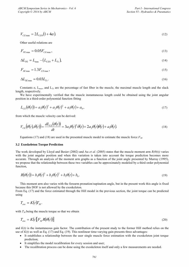
a 0.0050 d -231.72 b 1.2765 e 77.627 c 0.2024
f -173.71
Figure 4 shows the graphical representation of the parameters in Table I used in Eq. (1) to determine the force generated by the PAM on the allowed workspace. Together with the force surface, Fig. 4 plots the 360 experimental points used as reference for the model optimization with the GA.
Figure 4. PAM static force surface as a function of the relative contraction and pressure.
ABCM Symposium Series in Mechatronics - Vol. 6 Copyright © 2014 by ABCM
Part I - International Congress Section VI - Hydraulics & Pneumatics
762
4.2 Hill Muscle Model Optimization
To find the 22 constants for the physiological muscle, a similar strategy is proposed. However, for this application there is no experimental curve to be used as reference. To address this problem the dynamic equation of the exoskeleton arm is used to calculate the instantaneous torque, which is then compared with the GA estimation. This equation is the same as that of a two-DOF planar manipulator which is well known and defined by the matricial equation
,, qGqqqCqqH (23)
where H is the inertia matrix, C is the centrifugal and Coriolis effect matrix, G is the gravitational torque vector, q is the joints angular posisiton vector, and τ is the torque vector applied to the joints. The angles and axes used are the same as those on Fig. 2 and the inertia and distance parameters for the model were obtained with the exoskeleton SolidWorks CAD model.
For the GA optimization the muscle model has to be solved. Therefore we propose the following methodology to calculate the muscle force:
1. The raw sEMG is filtered and the neural activation level is calculated using Eq. (3);2. The exoskeleton joint angles measured by the potentiometers are filtered using a second-order Butterworthlow-pass filter (30 Hz cut-off) and then differentiated to estimate the joint velocities; 3. From the angles and velocities it is possible to calculate LCE, Δ LCE, VCE, and R;4. Hence, we obtain fl, fv and FCE, which is equal to FSE.5. From Eq. (7) it is possible to find the SE displacement, add that value to the CE displacement to get the PEdisplacement; 6. Again from Eq. (7) we can calculate the force on PE and add that value to FCE to obtain the total muscle force.7. From FM we can finally calculate Texo using Eq. (20).In this application, the RMSE function did not present satisfactory results as fitness function, hence we adopted
N
i dyn
GA
iFiFfit
1.12 (24)
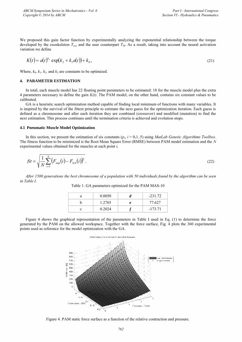
For this optimization 2500 generations were necessary to converge to the locally optimal solution for the 22 chromosomes. Table II presents all the values found for the Biceps Brachii.
Tabela 2: GA parameters for the Biceps Model
0.6100 a1 [m/rad-1] -2.3616LCE0 [m] 0.1181 a2 [m/rad-2] -1.8965 LTs [m] 0.2204 a3 [m/rad-3] -2.9782Lmax [m] 0.5278 b0 [m] -2.7137
FCEmax[N] 623.3 b1 [m/rad-1] 0.28850.726 b2 [m/rad-2] 0.1141 7.275 b3 [m/rad-3] 0.1777
2.7907 4.4781 -0.0794 -6.04470.5624 9.6687
a0[m] 2.7593 1.9063
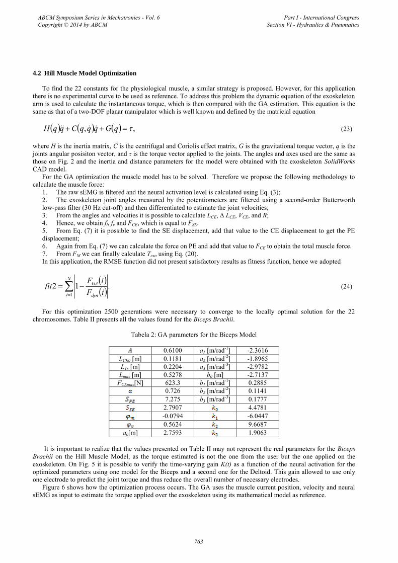
It is important to realize that the values presented on Table II may not represent the real parameters for the Biceps Brachii on the Hill Muscle Model, as the torque estimated is not the one from the user but the one applied on the exoskeleton. On Fig. 5 it is possible to verify the time-varying gain K(t) as a function of the neural activation for the optimized parameters using one model for the Biceps and a second one for the Deltoid. This gain allowed to use only one electrode to predict the joint torque and thus reduce the overall number of necessary electrodes.
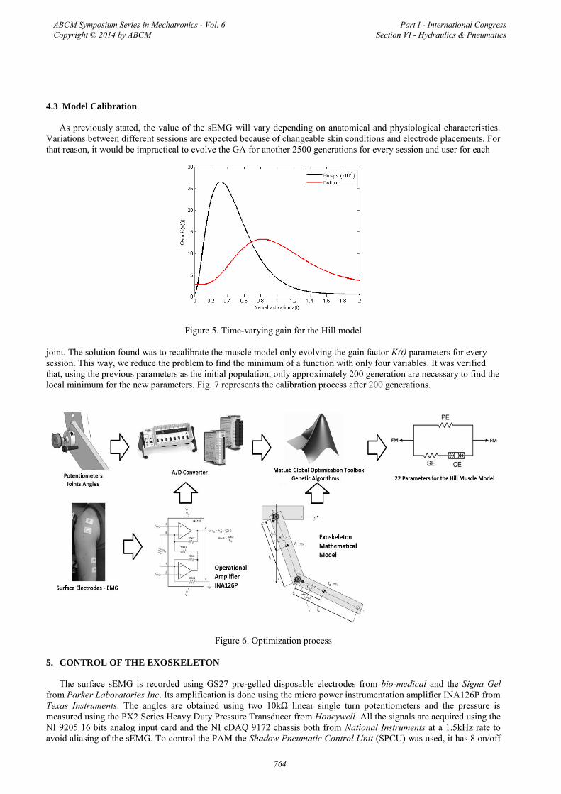
Figure 6 shows how the optimization process occurs. The GA uses the muscle current position, velocity and neural sEMG as input to estimate the torque applied over the exoskeleton using its mathematical model as reference.
ABCM Symposium Series in Mechatronics - Vol. 6 Copyright © 2014 by ABCM
Part I - International Congress Section VI - Hydraulics & Pneumatics
763
4.3 Model Calibration
As previously stated, the value of the sEMG will vary depending on anatomical and physiological characteristics. Variations between different sessions are expected because of changeable skin conditions and electrode placements. For that reason, it would be impractical to evolve the GA for another 2500 generations for every session and user for each
Figure 5. Time-varying gain for the Hill model
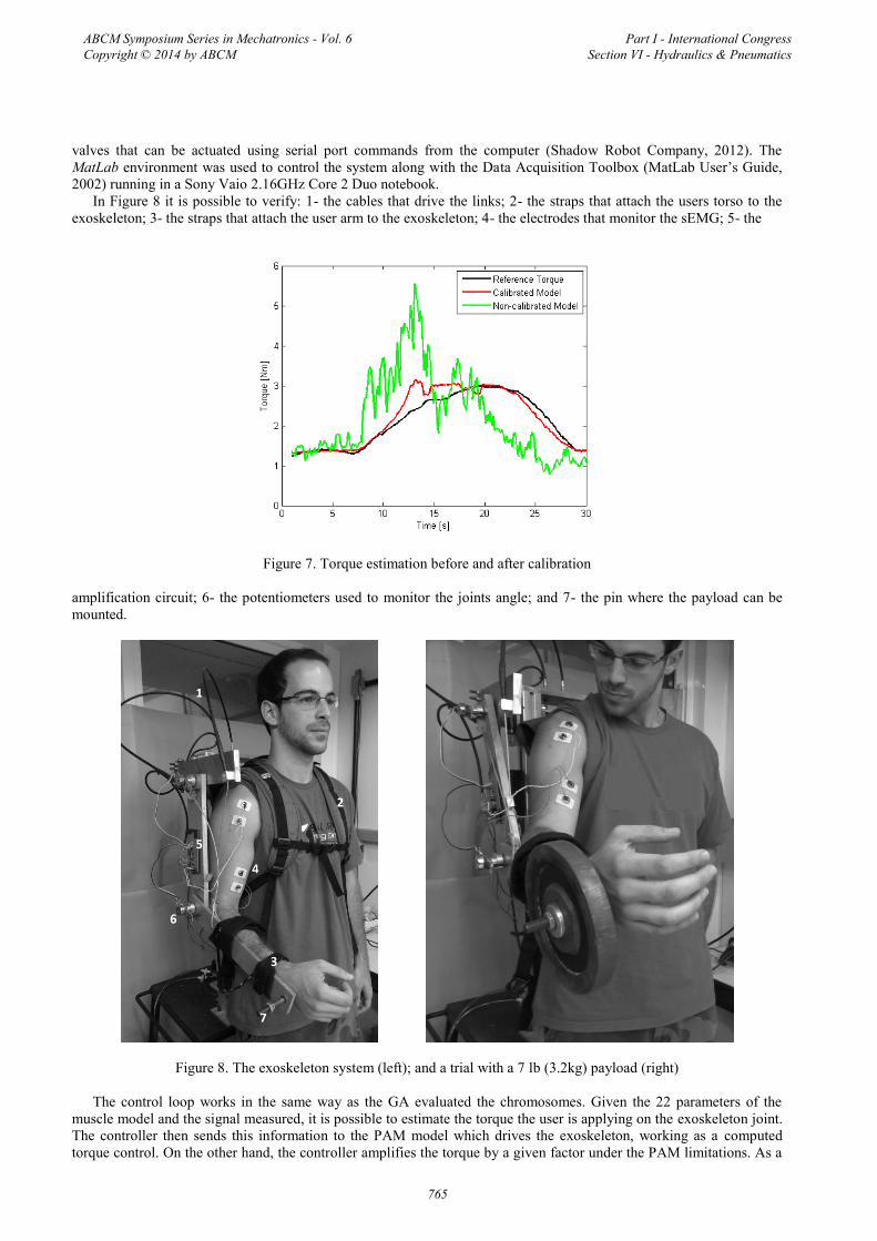
joint. The solution found was to recalibrate the muscle model only evolving the gain factor K(t) parameters for every session. This way, we reduce the problem to find the minimum of a function with only four variables. It was verified that, using the previous parameters as the initial population, only approximately 200 generation are necessary to find the local minimum for the new parameters. Fig. 7 represents the calibration process after 200 generations.
Figure 6. Optimization process
5. CONTROL OF THE EXOSKELETON
The surface sEMG is recorded using GS27 pre-gelled disposable electrodes from bio-medical and the Signa Gelfrom Parker Laboratories Inc. Its amplification is done using the micro power instrumentation amplifier INA126P from Texas Instruments. The angles are obtained using two 10kΩ linear single turn potentiometers and the pressure is measured using the PX2 Series Heavy Duty Pressure Transducer from Honeywell. All the signals are acquired using the NI 9205 16 bits analog input card and the NI cDAQ 9172 chassis both from National Instruments at a 1.5kHz rate to avoid aliasing of the sEMG. To control the PAM the Shadow Pneumatic Control Unit (SPCU) was used, it has 8 on/off
ABCM Symposium Series in Mechatronics - Vol. 6 Copyright © 2014 by ABCM
Part I - International Congress Section VI - Hydraulics & Pneumatics
764
valves that can be actuated using serial port commands from the computer (Shadow Robot Company, 2012). The MatLab environment was used to control the system along with the Data Acquisition Toolbox (MatLab User’s Guide, 2002) running in a Sony Vaio 2.16GHz Core 2 Duo notebook.
In Figure 8 it is possible to verify: 1- the cables that drive the links; 2- the straps that attach the users torso to the exoskeleton; 3- the straps that attach the user arm to the exoskeleton; 4- the electrodes that monitor the sEMG; 5- the
Figure 7. Torque estimation before and after calibration
amplification circuit; 6- the potentiometers used to monitor the joints angle; and 7- the pin where the payload can be mounted.
Figure 8. The exoskeleton system (left); and a trial with a 7 lb (3.2kg) payload (right)
The control loop works in the same way as the GA evaluated the chromosomes. Given the 22 parameters of the muscle model and the signal measured, it is possible to estimate the torque the user is applying on the exoskeleton joint. The controller then sends this information to the PAM model which drives the exoskeleton, working as a computed torque control. On the other hand, the controller amplifies the torque by a given factor under the PAM limitations. As a
ABCM Symposium Series in Mechatronics - Vol. 6 Copyright © 2014 by ABCM
Part I - International Congress Section VI - Hydraulics & Pneumatics
765
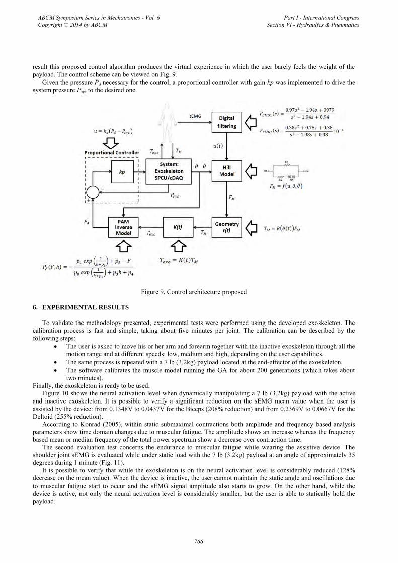
result this proposed control algorithm produces the virtual experience in which the user barely feels the weight of the payload. The control scheme can be viewed on Fig. 9.
Given the pressure Pd necessary for the control, a proportional controller with gain kp was implemented to drive the system pressure Psys to the desired one.
Figure 9. Control architecture proposed
6. EXPERIMENTAL RESULTS
To validate the methodology presented, experimental tests were performed using the developed exoskeleton. The calibration process is fast and simple, taking about five minutes per joint. The calibration can be described by the following steps:
The user is asked to move his or her arm and forearm together with the inactive exoskeleton through all themotion range and at different speeds: low, medium and high, depending on the user capabilities.
The same process is repeated with a 7 lb (3.2kg) payload located at the end-effector of the exoskeleton. The software calibrates the muscle model running the GA for about 200 generations (which takes about
two minutes).Finally, the exoskeleton is ready to be used.
Figure 10 shows the neural activation level when dynamically manipulating a 7 lb (3.2kg) payload with the active and inactive exoskeleton. It is possible to verify a significant reduction on the sEMG mean value when the user is assisted by the device: from 0.1348V to 0.0437V for the Biceps (208% reduction) and from 0.2369V to 0.0667V for the Deltoid (255% reduction).
According to Konrad (2005), within static submaximal contractions both amplitude and frequency based analysis parameters show time domain changes due to muscular fatigue. The amplitude shows an increase whereas the frequency based mean or median frequency of the total power spectrum show a decrease over contraction time.
The second evaluation test concerns the endurance to muscular fatigue while wearing the assistive device. The shoulder joint sEMG is evaluated while under static load with the 7 lb (3.2kg) payload at an angle of approximately 35 degrees during 1 minute (Fig. 11).
It is possible to verify that while the exoskeleton is on the neural activation level is considerably reduced (128% decrease on the mean value). When the device is inactive, the user cannot maintain the static angle and oscillations due to muscular fatigue start to occur and the sEMG signal amplitude also starts to grow. On the other hand, while the device is active, not only the neural activation level is considerably smaller, but the user is able to statically hold the payload.
ABCM Symposium Series in Mechatronics - Vol. 6 Copyright © 2014 by ABCM
Part I - International Congress Section VI - Hydraulics & Pneumatics
766
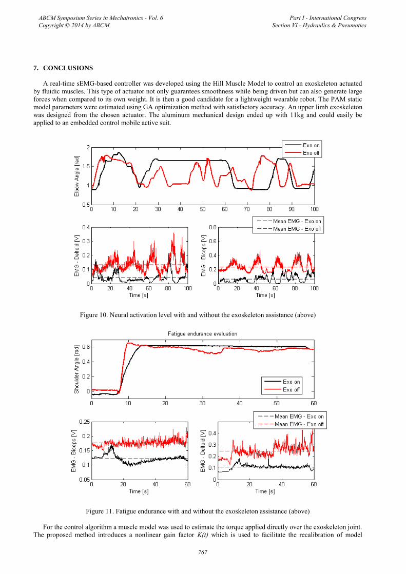
7. CONCLUSIONS
A real-time sEMG-based controller was developed using the Hill Muscle Model to control an exoskeleton actuatedby fluidic muscles. This type of actuator not only guarantees smoothness while being driven but can also generate large forces when compared to its own weight. It is then a good candidate for a lightweight wearable robot. The PAM static model parameters were estimated using GA optimization method with satisfactory accuracy. An upper limb exoskeleton was designed from the chosen actuator. The aluminum mechanical design ended up with 11kg and could easily be applied to an embedded control mobile active suit.
Figure 10. Neural activation level with and without the exoskeleton assistance (above)
Figure 11. Fatigue endurance with and without the exoskeleton assistance (above)
For the control algorithm a muscle model was used to estimate the torque applied directly over the exoskeleton joint. The proposed method introduces a nonlinear gain factor K(t) which is used to facilitate the recalibration of model
ABCM Symposium Series in Mechatronics - Vol. 6 Copyright © 2014 by ABCM
Part I - International Congress Section VI - Hydraulics & Pneumatics
767

parameters. The calibration process takes about five minutes for each joint and is able to converge in approximately 200 generations of the GA. The task of manipulating a 7 lb payload was performed and it is shown that the exoskeleton assistance reduces the neural activation level in over 200%. Also, the task of maintaining the static torque is facilitated, reducing de sEMG mean value in about 128%. The exoskeleton shares part of the torque necessary to lift the weight and the user supports only a part of the load, increasing the user overall strength and endurance, avoiding muscular fatigue.
Future work embraces the development of an embedded controller to make the exoskeleton mobile and the optimization of the mechanical structure to reduce its weight.
8. REFERENCES
Au, S., Bonato, P., Herr, H., “An EMG-position controlled system for an active ankle-foot prosthesis: An initial experimental study”, 9th International Conference on Rehabilitation Robotics, Chicago, IL, USA, June 2005.
“Basics of Surface Electromyography Applied to Physical Rehabilitation and Biomechanics”, Thought Technology Ltd., 2009/2010
Cavallaro, E., Rosen, J., Perry, J., Burns, S., “Real-Time Myoprocessors for a Neural Controlled Powered Exoskeleton Arm”, IEEE Transactions on Biomedical Engineering, Vol. 53, No. 11, November 2006.
Cavallaro, E., Rosen, J., Perry, J., Burns, S., Hannaford, B., “Hill-Based Model as a Myoprocessor for a Neural Controlled Powered Exoskeleton Arm – Parameters Optimization”, International Conference on Robotics and Automation, Barcelona, Spain, April 2005.
“Data Acquisition Toolbox For Use With MatLab”, User’s Guide, version 2, The MathWorks, 2002. De Luca, C. J. “The Use of Surface Electromyography in Biomechanics”, Wartenweiler Memorial Lecture, The
International Society for Biomechanics, 1993. Fleisher, C. “Controlling Exoskeletons with EMG signals and a Biomechanical Body Model”, Ph.D. Thesis, Technical
University of Berlin, Germany, 2007. Fluidic Muscle DMSP/MAS – Festo Catalogue, FESTO, 2010. Gopura, R. A. R. C., Kiguchi, K., “Mechanical Designs of an Active Upper-Limb Exoskeleton Robots: State-of-the-Art
and Design Difficulties” 2009 IEEE, 11st International Conference on Rehabilitation Robotics, Kyoto International Conference Center, Japan, June 2009.
Gordon, M., Huxley, A., Julian, F., “The Variation in Isometric Tension with Sarcomere Length in Vertebrate Muscle Fibres”, Department of Physiology, University College London, September 1965.
Hill, A. V., “The heat of shortening and the dynamic constants of muscle”, Proc. R. Soc. London Ser B, 126, (1938), pp. 136-195.
Kobayashi, H., Aida, T., and Hashimoto, T., “Muscle Suit Development and Factory Application”, International Journal of Automation Technology Vol. 3, No. 6, 2009.
Konrad, P., “The ABC of EMG: Practical Introduction to Kinesiological Electromyography”, Version 1.0, 2005. Lloyd, D., Besier, T., “An EMG-driven musculoskeletal model to estimate muscle forces and knee joint mometns in
vivo”, Journal of Biomechanics, Elsevier, December 2002. Luh, J., Chang, G., Cheng, C., Lai, J., Kuo, e., “Isoknetic elbow joint torques estimation from surface EMG and
kinematic data: using an artificial neural network model”, Journal of Electromyography and Kinesiology, Elsevier, May 1998.
Murray, W., Delp, S., Buchanan, T., “Variation of Muscle Moment Arms with Elbow and Forearm Position”, J. Biomechanics, Vol. 28, No 5., 1995.
Ormiga, A., “Controle de um Manipulador Robótico Através de uma Interface Cérebro Máquina Não-Invasiva com Aprendizagem Mútua”, M.Sc. Dissertation, PUC-Rio, Rio de Janeiro, Brazil, August 2010.
Rash, G.S., “Electromyography Fundamentals”, DelSys Inc., 2003. Rassier, D., MacIntosh, B., Herzog, W., “Length dependence of active force production in skeletal muscle”, Journal of
Applied Physiology, American Physiology Society, July de 2012. Rosen, J., Fuchs, M. B., Arcan, M., “Performances of Hill-Type and Neural Network Muscle Models – Towards a
Myosignal-Based Exoskeleton”, Department of Biomedical Engineering and Department of Solid Mechanics, Materials and Structures, Faculty of Engineering, Tel Aviv University, Israel, Setembro de 1998.
Shadow Robot Company, http://www.shadowrobot.com/, accessed on March 2012. Shao, Q., Bassett, N., Manal, K., Buchanan, T., “An EMG-driven model to estimate muscles forces and joint moments in
stroke patients”, Computers in Biology and Medicine, Elsevier, September 2009. Szepe, T., “Accurate force function approximation for pneumatic artificial muscles”, Department of Technical
Informatics, University of Szeged, Hungary.
ABCM Symposium Series in Mechatronics - Vol. 6 Copyright © 2014 by ABCM
Part I - International Congress Section VI - Hydraulics & Pneumatics
768