sensoresdecorrosaoestruturasportuguesas
DESCRIPTION
monitorizaçãoTRANSCRIPT

DURATINET PARTNERS
PORTUGALLaboratório Nacional de Engenharia Civil, I.P. (LNEC)Estradas de Portugal, SA (EP)REFER, E.P.TEIXEIRA DUARTE – Engenharia e Construções, S.A.Administração do Porto de Lisboa (APL)Fundo para o Desenvolvimento das Ciências da Construção (FUNDCIC)
FRANCEInstitut français des sciences et technologies des transports, de l’aménagement et des réseaux (IFSTTAR)Université de BordeauxUniversité de NantesUniversité de La RochelleConseil General de la Charente-Maritime (CG-17)
IRELANDDublin University- Trinity College (TCD)National Roads Authority (NRA)
SPAINUniversidade de Vigo (UV)Porto de VigoXunta da Galiza
UNITED KINGDOMQueen’s University Belfast (QUB)
TECHNICAL REPORT
TR 6.5CORROSION MONITORING SYSTEMS
INSTALLED IN PORTUGUESE STRUCTURES
smart & green • structural and repair materials


smart & green
structural and repair materials
TECHNICAL REPORT
TR 6.5
CORROSION MONITORING SYSTEMS INSTALLED IN PORTUGUESE STRUCTURES
Authors:
Elsa Vaz Pereira
Manuela Salta
Authors:
Elsa Vaz Pereira
Researcher of LNEC
Manuela Salta
Principal researcher and head of Metallic Materials Division of LNEC
NOTE:
The contents of this report reflect the views of the authors, who are responsible for the facts and accuracy of the data presented.
i
PREFACE
This Technical Report (TR) is one of a series of technical reports which were prepared inside the DURATINET project working Group WG-A 6 “Smart & green structural materials” concerning new materials or systems which could improve the durability of structures and to reduce the carbon footprint associated to the construction and maintenance of structures.
In this TR results obtained from different corrosion monitoring systems installed in several Portuguese reinforced concrete structures are presented. The examples presented refer to systems in build in new structures and systems specially designed to evaluate the performance of different repair options in existing concrete structures damaged by reinforcement corrosion and which were submitted to repair/rehabilitation.
WG A6 – Smart and green structural and repair materials
WG Leader:
X. Ramon Novoa Vigo University , SP
Partners active members
Country Institution Members
Portugal LNEC Manuela Salta, Maria João, Elsa V. Pereira, Susana Cabral-Fonseca
University of Bordeaux
Sylvie Yotte
UK Queen’s University Belfast
Muhammed Basheer, David Cleland, Sree V. Nanukuttan, Sudarshan Srinivasan
ii
DURATINET project approved by the Atlantic Area Programme and co-financed by ERDF
CONTRACT Nº: 2008-1/049
ACRONYM: DURATINET
PROJECT TITLE: Durable Transport Infrastructure in the Atlantic Area Network
Laboratório Nacional de Engenharia Civil (LNEC, IP)
Materials Department
Manuela Salta
iii
CONTENTS
1 Introduction ..................................................................................................................... 1
2 Design of the corrosion monitoring systems .................................................................... 2
3 Application in Portuguese Structures ............................................................................... 5
3.1 New structures ............................................................................................................... 5
3.1.1 Funchal Airport in Madeira Island ............................................................................. 5
3.1.2 Infante D. Henrique Bridge ..................................................................................... 10
3.2 Repaired structures ..................................................................................................... 13
3.2.1 Barra Bridge at Aveiro ............................................................................................ 13
3.2.2 Edgar Cardoso Bridge ............................................................................................ 22
3.2.3 Silo for cereals ....................................................................................................... 32
4 Bibliography ...................................................................................................................... 37


CORROSION MONITORING SYSTEMS
1
1 Introduction
Structural deterioration of reinforced concrete structures affected by corrosion is a gradual process consisting of a few phases during service life, including corrosion initiation, concrete cracking, excessive deflection and final collapse due to loss of structural strength.
The use of permanent monitoring systems to assess the corrosion of ordinary reinforcement in concrete has been recognised as an important tool to prevent premature deterioration of reinforced concrete (RC) structures and to assist the development of reliable models that allow designing durable new structures in aggressive environments and to establish rational maintenance and repair strategies of reinforced concrete structures affected by reinforcement corrosion.
Though it is well known that the selection of parameters to be measured in each particular situation as well as the locals of the structures to be instrumented are critical for the success of each installed system, more advances are still needed, especially in the development of sensors suitable for measuring the selected parameters in existing concrete structures.
The most relevant advances in the development of corrosion monitoring systems have been achieved in the proposal of embedded sensors for application in new structures. For these structures sensors are embedded during concreting and the electrolytic contact between the sensor and the concrete is warranted, being possible, at present, to measure, continuously, the corrosion potential, the corrosion rate, the concrete resistivity and the concrete chloride contents in new structures.
For existing structures sensors have to be fixed after concreting. The electrolytic contact between the original concrete and the sensors is much more difficult to be established in a non–intrusive way and few systems have been proposed, being more advances in this field still needed. Sensors are usually installed inside holes, being the electrolytic contact between the original concrete and the sensor established by pressing the sensor to the concrete or by using sealing materials.

SMART & GREEN STRUCTURAL AND REPAIR MATERIALS
2
2 Design of the corrosion monitoring systems
The selection of the parameters to be measured in each particular situation as well as the locals of the structures to be instrumented are critical for the success of each installed system.
In the corrosion initiation period, during which the aggressive agents penetrate in the concrete cover until reach the steel, the most relevant parameter in marine environment is the chloride content. In industrial or indoor applications were extensive carbonation could develop; carbonation front and humidity are usually followed.
On the propagation period, during which the rebar corrodes until a maximum tolerable level of damage, corrosion rate has been identified as the most relevant parameter in the corrosion.
If organic inhibitors are applied to the concrete surface, to reduce corrosion, it will be important to know the effectiveness of penetration inside the concrete cover and to obtain information about the corrosion rate of steel in the contaminated concrete.
When surface treatments are used to prevent or reduce the penetration of water, besides the control of evolution of moisture inside concrete, it is also necessary to follow the loss of the protective properties of the surface treatments with time in order to define intervals of repainting that allow an effective control of costs.
The locals of the structure to be instrumented are usually the locals most likely to develop reinforcement corrosion. Thus, selected locals with specific aspects of structural design or construction practices are often chosen (concreting joints and expansion joints, areas of high density of rebars, corner areas, etc.). Also environmental exposure conditions particularly aggressive are the usually selected (areas of condensation in general and tidal and splash zones in marine structures).
Monitoring corrosion systems installed in Portuguese structures are constituted by the following sensors appropriated to be embedded in concrete: galvanic current sensors, corrosion potential sensors, concrete resistivity sensors and thermometers.
In new structures or repaired structures where all the original concrete cover is completely removed, galvanic current sensors are usually used to follow the progress of aggressive agents in concrete like chloride ions or carbonation (Fig. 1). When the despassivation front is detected in the small sections of low carbon steel electrodes embedded in the concrete cover at different depths, addition protection systems could be decided, like the application of protective coatings.
Fig.1. Anode ladder type galvanic sensor (GS-AL)
Anode
Anode
Cathode
Automatic acquisition
of data
Surface

CORROSION MONITORING SYSTEMS
3
Galvanic current sensors have also been installed in existing structures to follow the effect of corrosion inhibitors or coatings. In that case, typically, concrete cores with a small section of rebar surrounded by the contaminated concrete are removed from the structure. The core is instrumented in lab using the steel embedded in concrete as an anode and a stainless steel electrode as the cathode. After instrumentation the galvanic current cell is replaced in the original site, using sealants materials (Fig. 2). Repair materials like corrosion inhibitors or protective coating are then applied on concrete surface. In Fig. 3 the instrumentation of an existing RC structure is illustrated (usually several sensors are installed simultaneously).
Fig. 2. Core type galvanic sensor (GS-C)
Fig. 3. Example of the instrumentation of an existing RC structure damaged by reinforcement corrosion and submitted to repair works.
In new structures corrosion potential is also always measured to detect the beginning of reinforcement corrosion. For the measurement, reference electrodes of MnO2 are usually installed in different locals. Activated titanium has also been used in some applications. In existing structures reference electrodes are also always installed in holes made wilfully and that are subsequently filled with an appropriate mortar. In areas of the structures already contaminated with aggressive agents, the measurement of corrosion potential can provide information on the influence of repair procedures (removal of contaminated concrete surrounding the reinforcement, application of corrosion inhibitors, application of protective coatings, etc.).
The measurement of electric resistance of concrete can provide important information about the progression of despassivation front, the saturation degree of concrete and the effectiveness of corrosion protection systems and, therefore, resistivity sensors are also always installed.
Surface
Steel
Automatic acquisition of data
Anode Cathode

SMART & GREEN STRUCTURAL AND REPAIR MATERIALS
4
In addition temperature sensors are also always installed since this parameter directly influences the corrosion rate of reinforcement and transport properties of aggressive agents in concrete cover.
The acquisition of data is performed with automatic acquisition systems. These systems can send data by phone communication, however periodic maintenance of the systems should be provided in the project. Most of the failures are due to lack of maintenance, especially in the non-replacement of the internal batteries of the acquisition systems.
In the following chapters different corrosion monitoring systems installed in Portuguese reinforced concrete structures are presented Fig. 4. The examples presented refer to systems installed in new structures to prevent the beginning of reinforcement corrosion and systems specially designed to evaluate the performance of different repair options applied in existing concrete structures damaged by reinforcement corrosion.
Fig. 4. Location of the structures instrumented.
Repaired
New
CORROSION MONITORING SYSTEMS
5
3 Application in Portuguese Structures
3.1 New structures
3.1.1 Funchal Airport in Madeira Island
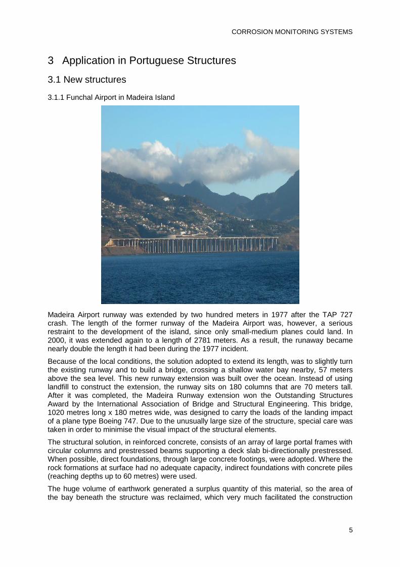
Madeira Airport runway was extended by two hundred meters in 1977 after the TAP 727 crash. The length of the former runway of the Madeira Airport was, however, a serious restraint to the development of the island, since only small-medium planes could land. In 2000, it was extended again to a length of 2781 meters. As a result, the runaway became nearly double the length it had been during the 1977 incident.
Because of the local conditions, the solution adopted to extend its length, was to slightly turn the existing runway and to build a bridge, crossing a shallow water bay nearby, 57 meters above the sea level. This new runway extension was built over the ocean. Instead of using landfill to construct the extension, the runway sits on 180 columns that are 70 meters tall. After it was completed, the Madeira Runway extension won the Outstanding Structures Award by the International Association of Bridge and Structural Engineering. This bridge, 1020 metres long x 180 metres wide, was designed to carry the loads of the landing impact of a plane type Boeing 747. Due to the unusually large size of the structure, special care was taken in order to minimise the visual impact of the structural elements.
The structural solution, in reinforced concrete, consists of an array of large portal frames with circular columns and prestressed beams supporting a deck slab bi-directionally prestressed. When possible, direct foundations, through large concrete footings, were adopted. Where the rock formations at surface had no adequate capacity, indirect foundations with concrete piles (reaching depths up to 60 metres) were used.
The huge volume of earthwork generated a surplus quantity of this material, so the area of the bay beneath the structure was reclaimed, which very much facilitated the construction

SMART & GREEN STRUCTURAL AND REPAIR MATERIALS
6
works. Special care was taken on making the embankment, in order to minimise the impacts on the local environmental conditions.
Purpose of instrumentation
To obtain information about the progress of despassivation front in the concrete cover (carbonation and chlorides ingress) in the Madeira runway extension.
Location of the instrumentation
A monitoring system consisting of corrosion sensors embedded with automatic data acquisition was installed.
Instrumentation was installed in 23 areas. The localization of the areas took into account the influence of differential exposure conditions and specific aspects of structural design or construction practices.
Sensors and measurement equipment
Sensors
In each of the 23 areas the following set of sensors were installed:
Galvanic cell - anode ladders type galvanic sensor (GS-AL).
Resistivity sensors – Two graphite electrode resistivity sensors
Temperature – Pt100 thermometer appropriated to be embedded in concrete
Corrosion potential – ERE-Probe reference electrode from Germann Instruments and activated Ti.
Fig. 5. Sensors before concreting.
CORROSION MONITORING SYSTEMS
7
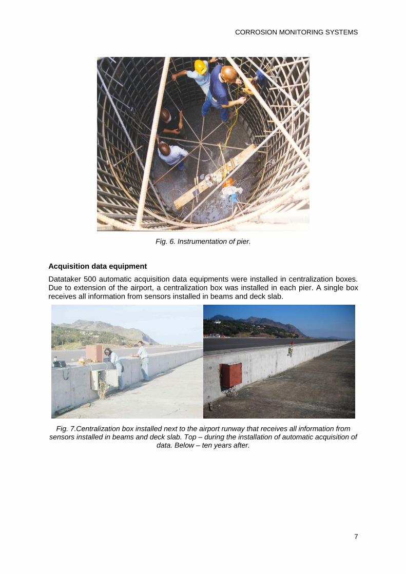
Fig. 6. Instrumentation of pier.
Acquisition data equipment
Datataker 500 automatic acquisition data equipments were installed in centralization boxes. Due to extension of the airport, a centralization box was installed in each pier. A single box receives all information from sensors installed in beams and deck slab.
Fig. 7.Centralization box installed next to the airport runway that receives all information from sensors installed in beams and deck slab. Top – during the installation of automatic acquisition of
data. Below – ten years after.
SMART & GREEN STRUCTURAL AND REPAIR MATERIALS
8
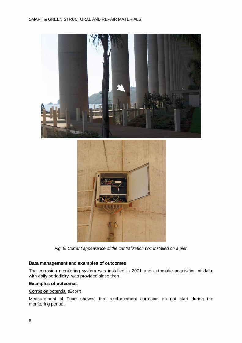
Fig. 8. Current appearance of the centralization box installed on a pier.
Data management and examples of outcomes
The corrosion monitoring system was installed in 2001 and automatic acquisition of data, with daily periodicity, was provided since then.
Examples of outcomes
Corrosion potential (Ecorr)
Measurement of Ecorr showed that reinforcement corrosion do not start during the monitoring period.

CORROSION MONITORING SYSTEMS
9
Galvanic Current (Igal)
Galvanic currents measured during the monitoring period are low and indicative that the reinforcement is not corroding.
Concrete electrical resistance (R)
No significant changes of R occurred during the monitoring period. R variations have been attributed to the variations of environmental parameters and to the evolution of concrete hydration over time.
-600
-500
-400
-300
-200
-100
0
N-01 J-02 M-03 N-03 A-04 A-05 D-05 A-06 A-07 J-08 S-08 M-09 J-10 S-10
Data
Eco
rr (
mV
)
V2P
-5.E-06
-3.E-06
0.E+00
3.E-06
5.E-06
N-01 J-02 M-03 N-03 A-04 A-05 D-05 A-06 A-07 J-08 S-08 M-09 J-10 S-10
Data
I ga
l (A
)
V1M
V2M
V3M
0
2000
4000
6000
8000
10000
12000
N-01 J-02 M-03 N-03 A-04 A-05 D-05 A-06 A-07 J-08 S-08 M-09 J-10 S-10
Data
R (
Oh
m)
V2R
V3R

SMART & GREEN STRUCTURAL AND REPAIR MATERIALS
10
3.1.2 Infante D. Henrique Bridge
Infante D. Henrique Bridge, is a concrete bridge 380 m long that crosses the river 70 m above the riverbed. It has a 280 m span and a 20 m wide deck, with two traffic lanes. It consists of an unusually lowered laminar arch, a 280 m span with a 25 m rise contrasting with the considerable rigidity of the deck.
The deck has a box girder section and a constant height of 11 m. It is supported on piers set 35 m apart. The polygonal laminar arch has a constant thickness of 1,5 m and its width varies between 20 m at the abutments and 10 m in the central deck area, which is 70 m long. At the abutment the arc has been lightened to reduce its weight. In this zone the riverbed is approximately 160 m wide.
0
10
20
30
40
N-01 J-02 M-03 N-03 A-04 A-05 D-05 A-06 A-07 J-08 S-08 M-09 J-10 S-10
Data
T (
ºC)
V1T
V2T
CORROSION MONITORING SYSTEMS
11
The construction began on 1999, being the corrosion monitoring system installed during construction.
Purpose of instrumentation
To obtain information about the progress of despassivation front in the concrete cover (carbonation and chlorides ingress).
Location of the instrumentation
A monitoring system consisting of corrosion sensors embedded with automatic data acquisition was installed.
Instrumentation was installed in 23 areas. The localization of the areas took into account the influence of differential exposure conditions and specific aspects of structural design or construction practices.
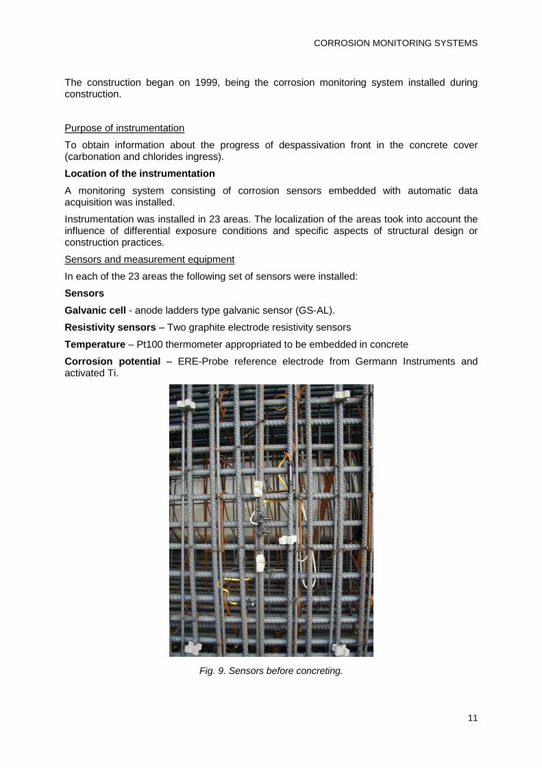
Sensors and measurement equipment
In each of the 23 areas the following set of sensors were installed:
Sensors
Galvanic cell - anode ladders type galvanic sensor (GS-AL).
Resistivity sensors – Two graphite electrode resistivity sensors
Temperature – Pt100 thermometer appropriated to be embedded in concrete
Corrosion potential – ERE-Probe reference electrode from Germann Instruments and activated Ti.
Fig. 9. Sensors before concreting.
SMART & GREEN STRUCTURAL AND REPAIR MATERIALS
12
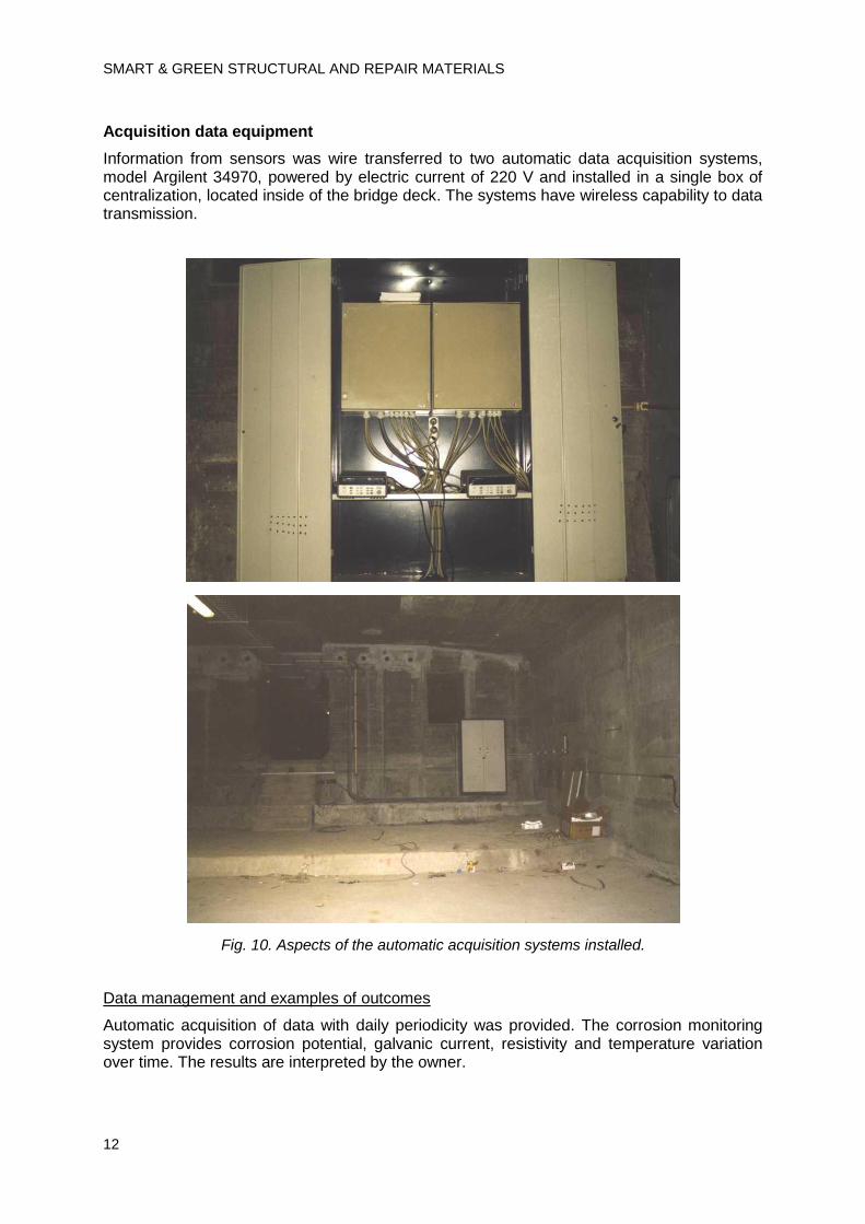
Acquisition data equipment
Information from sensors was wire transferred to two automatic data acquisition systems, model Argilent 34970, powered by electric current of 220 V and installed in a single box of centralization, located inside of the bridge deck. The systems have wireless capability to data transmission.
Fig. 10. Aspects of the automatic acquisition systems installed.
Data management and examples of outcomes
Automatic acquisition of data with daily periodicity was provided. The corrosion monitoring system provides corrosion potential, galvanic current, resistivity and temperature variation over time. The results are interpreted by the owner.
CORROSION MONITORING SYSTEMS
13
3.2 Repaired structures
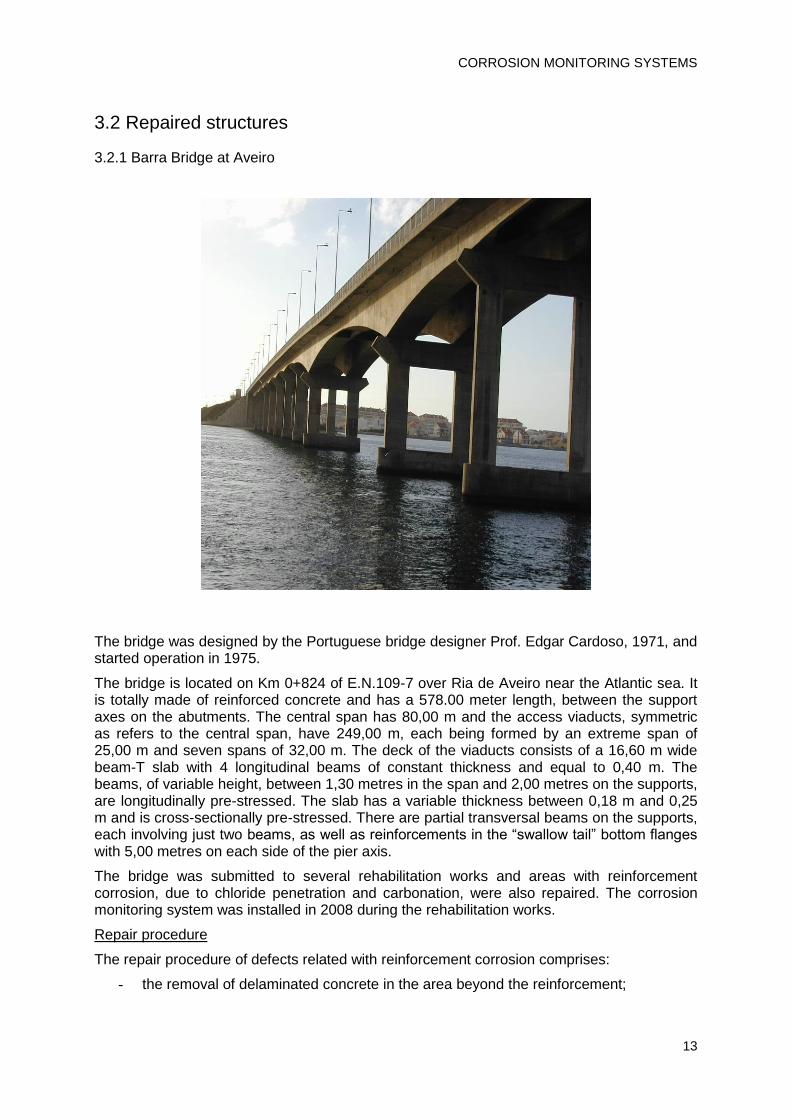
3.2.1 Barra Bridge at Aveiro
The bridge was designed by the Portuguese bridge designer Prof. Edgar Cardoso, 1971, and started operation in 1975.
The bridge is located on Km 0+824 of E.N.109-7 over Ria de Aveiro near the Atlantic sea. It is totally made of reinforced concrete and has a 578.00 meter length, between the support axes on the abutments. The central span has 80,00 m and the access viaducts, symmetric as refers to the central span, have 249,00 m, each being formed by an extreme span of 25,00 m and seven spans of 32,00 m. The deck of the viaducts consists of a 16,60 m wide beam-T slab with 4 longitudinal beams of constant thickness and equal to 0,40 m. The beams, of variable height, between 1,30 metres in the span and 2,00 metres on the supports, are longitudinally pre-stressed. The slab has a variable thickness between 0,18 m and 0,25 m and is cross-sectionally pre-stressed. There are partial transversal beams on the supports, each involving just two beams, as well as reinforcements in the “swallow tail” bottom flanges with 5,00 metres on each side of the pier axis.
The bridge was submitted to several rehabilitation works and areas with reinforcement corrosion, due to chloride penetration and carbonation, were also repaired. The corrosion monitoring system was installed in 2008 during the rehabilitation works.
Repair procedure
The repair procedure of defects related with reinforcement corrosion comprises:
- the removal of delaminated concrete in the area beyond the reinforcement;

SMART & GREEN STRUCTURAL AND REPAIR MATERIALS
14
- replacement or strengthening of the corroded reinforcement;
- replacement of concrete cover, followed by the application of a migrating corrosion inhibitor and a coating system.
Purpose of monitoring system
A monitoring system, consisting of arrays embedded corrosion sensors with several automatic data acquisition units was installed.
In areas without concrete cover removal the installation of the corrosion monitoring system aims to obtain information about the effect of migrating corrosion inhibitor and coating system application on the progress of reinforcement corrosion.
In areas with complete concrete removal the installation aims to obtain information about the progress of despassivation front in the concrete cover (carbonation and chlorides ingress).
Interface zones between areas with removal and no removal of concrete were also instrument to follow the possible occurrence of corrosion due to cracking in the interface of the hardened concrete and the new concrete.
Location of the instrumentation
Sensors were installed in eighteen areas. The localization of the areas took into account the influence of the different exposure conditions, the need to collect data on the effectiveness of the repair method used and to ensure the representativeness of the information collected by the monitoring system.
CORROSION MONITORING SYSTEMS
15
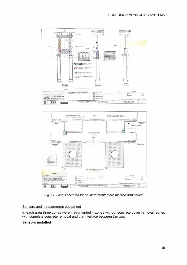
Fig. 11. Locals selected for be instrumented are marked with colour
Sensors and measurement equipment
In each area three zones were instrumented – zones without concrete cover removal, zones with complete concrete removal and the Interface between the two.
Sensors installed

SMART & GREEN STRUCTURAL AND REPAIR MATERIALS
16
Galvanic cell - In areas with complete removal of concrete cover an anode ladder type galvanic sensor was installed (GS-AL). In areas without concrete removal a core galvanic current sensor was installed (GS-C).
Resistivity sensors – Two graphite electrode resistivity sensors were used in the instrumentation of repaired and no repaired areas. In areas without concrete removal, a core was removed and instrumented with a resistivity sensor in order to preserve the concrete cover and to follow the influence of corrosion inhibitor applied on concrete surface as well as the coating performance over time.
Temperature – Pt100 thermometer appropriated to be embedded in concrete
Corrosion potential – ERE-Probe reference electrode from Germann Instruments and activated Ti. Reference electrodes were installed in areas with complete removal of concrete cover, in areas without concrete removal and in the interfacial zone between the two.
Fig. 12. Aspects of the three types of instrumented areas before concreting: areas with complete removal of concrete cover, areas without concrete removal and the interfacial zone between the two. In areas without concrete removal two cores instrumented are fixed, one with a resistivity
sensor and one with a galvanic current sensor. A reference electrode was installed in the interfacial zone.
CORROSION MONITORING SYSTEMS
17
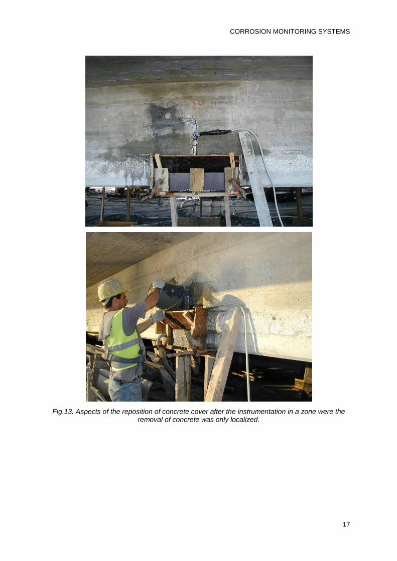
Fig.13. Aspects of the reposition of concrete cover after the instrumentation in a zone were the removal of concrete was only localized.

SMART & GREEN STRUCTURAL AND REPAIR MATERIALS
18
Fig. 14. Aspects of the reposition of concrete cover after the instrumentation in a zone were all the concrete cover was removed.
Fig. 15. Instrumentation of an area were extensive removal of concrete took place.

CORROSION MONITORING SYSTEMS
19
Fig.16.Cables from the sensors were conducted through external pipes to centralization boxes where the systems of data acquisition were installed.
Small slabs were also instrumented with the same sensors to follow the performance of the repair materials, in lab, in accelerated conditions.
Fig.17. Concrete slab with sensors installed for lab tests.
SMART & GREEN STRUCTURAL AND REPAIR MATERIALS
20
Acquisition data equipment
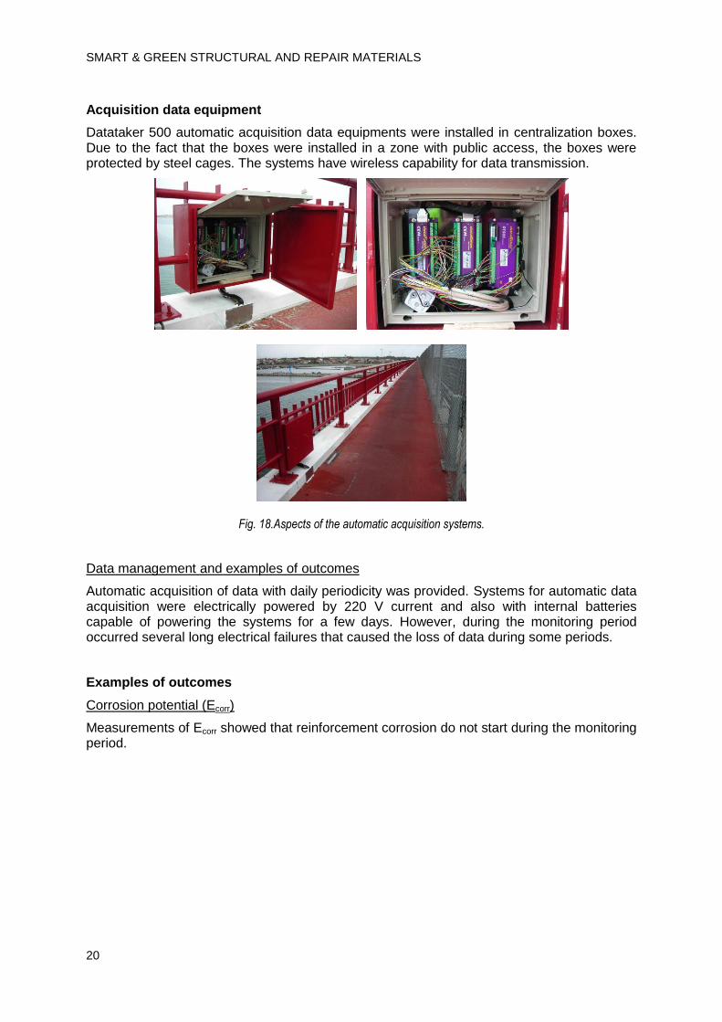
Datataker 500 automatic acquisition data equipments were installed in centralization boxes. Due to the fact that the boxes were installed in a zone with public access, the boxes were protected by steel cages. The systems have wireless capability for data transmission.
Fig. 18.Aspects of the automatic acquisition systems.
Data management and examples of outcomes
Automatic acquisition of data with daily periodicity was provided. Systems for automatic data acquisition were electrically powered by 220 V current and also with internal batteries capable of powering the systems for a few days. However, during the monitoring period occurred several long electrical failures that caused the loss of data during some periods.
Examples of outcomes
Corrosion potential (Ecorr)
Measurements of Ecorr showed that reinforcement corrosion do not start during the monitoring period.

CORROSION MONITORING SYSTEMS
21
Galvanic Current (Igal)
Galvanic currents measured during the monitoring period are low and indicative that the reinforcement is not corroding.
Concrete electrical resistance (R)
In the majority of the instrumented zones no significant changes of R occurred during the monitoring period and R variations have been attributed to the variations of environmental parameters. However in some places a sharp decrease of R values was detected and attributed to the formation of cracks in the concrete cover.
P8-P9 Jusante
-700
-600
-500
-400
-300
-200
-100
0
Jul/08 Set/08 Nov/08 Jan/09 Mar/09 Mai/09 Jul/09 Out/09 Dez/09 Fev/10 Abr/10 Jun/10 Ago/10 Out/10 Jan/11
Data
Ec
orr v
s M
nO
2/
mV
E_R
E_I
E_N
P8-P9 Jusante
-3.0E-05
-2.5E-05
-2.0E-05
-1.5E-05
-1.0E-05
-5.0E-06
0.0E+00
5.0E-06
Jul/08 Set/08 Nov/08 Jan/09 Mar/09 Mai/09 Jul/09 Out/09 Dez/09 Fev/10 Abr/10 Jun/10 Ago/10 Out/10 Jan/11
Data
I /A
I_R_15
I_R_30
I_N_R

SMART & GREEN STRUCTURAL AND REPAIR MATERIALS
22
3.2.2 Edgar Cardoso Bridge
Description of structure
Edgar Cardoso Bridge over the River Mondego, also known as Figueira da Foz Bridge, was designed by Portuguese engineer Edgar Cardoso and was inaugurated in 1982.
The bridge is located on Figueira da Foz, in coastline central Portugal and was subjected to a general rehabilitation during two years, which was given by completed on July 28 of 2005.
P8-P9 Jusante
0
3000
6000
9000
12000
Jul/08 Set/08 Nov/08 Jan/09 Mar/09 Mai/09 Jul/09 Out/09 Dez/09 Fev/10 Abr/10 Jun/10 Ago/10 Out/10 Jan/11
Data
R /
Oh
m
R_R_15
R_R_30
R_N_15
R_N_30

CORROSION MONITORING SYSTEMS
23
Edgar Cardoso Bridge includes a 405 m long cable stayed bridge with a steel deck and a main span of 225 m and two prestressed concrete approach viaducts with 45 m spans and a total length of 905 m.
The cable stayed bridge has a central span of 225 m and lateral spans of 90 m. The 85 m above the water level masts include four hollow concrete inclined elements. The stays, spaced 30 m at the deck, are made of galvanized wires passing through saddles at the top of the masts. The deck is a steel construction with two main beams, where the cable stays are fixed (each one made of two 2 m high I beams) interconnected by transverse beams spaced 10 m. These transverse beams support longitudinal girders spaced 8,20 m which in turn support a reinforced concrete slab with a variable thickness of 0,13 m to 0,20 m.
The deck of the approach viaducts have a slab 0,18 m (span) to 0,22 m (over the girders) thick supported by 4 longitudinal beams, spaced 5,20 m with 45 m spans. The prestressed concrete girders have a section of 0,40 m x 2 m at mid span and o,60 m x 2,50 m at the supports. The slab is prestressed in the transverse beams of the columns by dowels and plumb bearings. Only in the transition pier to the cable stayed bridge the support of the deck allows relative horizontal movements. The longitudinal beams are also interconnected by transverse beams spaced 15 m. Each support alignment has 2 hollow rectangular columns 3 m x 1,60 m connected at the top by a hollow rectangular beam 4,00 m x1,60 m, with a thickness of 0,25 m. The abutments are apparent. The deck is fixed to the abutment.
A detailed inspection showed that:
- The quality of execution was low. Concreting defects such as voids in prestressed concrete beams and low reinforcement cover were frequent. The painting of the steel structures was also of poor quality.
- Due to the quality of the concrete and to the defective execution, reinforcement corrosion represented a significant anomaly.
- Locally alkalis silica reactions and sulphate attack were identified (mainly in the foundations of the tower).
- In the approach viaducts the prestressed longitudinal girders were not conceived to avoid cracking in service conditions and cracks of 0,2-0,3 mm were frequent.
- In the cable stayed bridge there is a permanent tensile reaction at the transition piers, requiring a redundancy of the anchorage system for safety and reliability.
- The seismic design did not guarantee the seismic resistance required by the new codes and for the approach viaducts the decks were fixed to the abutments, generating considerable seismic forces.
The rehabilitation included the strengthening of the towers and the replacement of the anchorage system of the deck of the cable stayed bridge to the transition piers. The rehabilitation of the approach viaducts included the strengthening of the deck main girders by external prestressing and the introduction of new dissipating devices between the deck and the abutments. The general rehabilitation also includes local repairing and new surface protection of steel and concrete elements.
The bridge was submitted to several rehabilitation works and areas with reinforcement corrosion, due to chloride penetration and carbonation, were also repaired. The corrosion monitoring system was installed during the rehabilitation works.

SMART & GREEN STRUCTURAL AND REPAIR MATERIALS
24
Rehabilitation procedure
General rehabilitation of concrete structures included local concrete replacement and concrete surface protection. When local repairing involved a thickness greater than 6 cm, micro concrete was used (obtained from a mixture of 70% of per packed grout with 30% of weight of 9 mm aggregates). The rehabilitation procedure of defects related with reinforcement corrosion comprises:
- the removal of delaminated concrete in the area beyond the reinforcement;
- replacement or strengthening of the corroded reinforcement;
- replacement of concrete cover, followed by the application of a migrating corrosion inhibitor and a coating system.
Purpose of instrumentation
In areas without concrete cover removal the installation of the corrosion monitoring system aims to obtain information about the effect of migrating corrosion inhibitor and coating system in the progress of reinforcement corrosion.
In areas with complete concrete removal the installation aims to obtain information about the progress of despassivation front in the concrete cover (carbonation and chlorides ingress).
Interface zones between areas with removal and no removal of concrete were also instrument to follow the possible occurrence of corrosion due to cracking in junction of original concrete and repair material.
Location of the sensors
A monitoring system, consisting of corrosion sensors embedded in concrete, was installed with automatic data acquisition.
Arrays of embedded sensors were installed in 33 areas. The localization of the areas took into account the influence of differential exposure conditions, the need to collect data on the effectiveness of the repair method used and ensure the representativeness of the information collected by the system.

CORROSION MONITORING SYSTEMS
25
Fig. 19. Locals selected for be instrumented are marked with colour
Data acquisition
SMART & GREEN STRUCTURAL AND REPAIR MATERIALS
26
Sensors and measurement equipment
Sensors
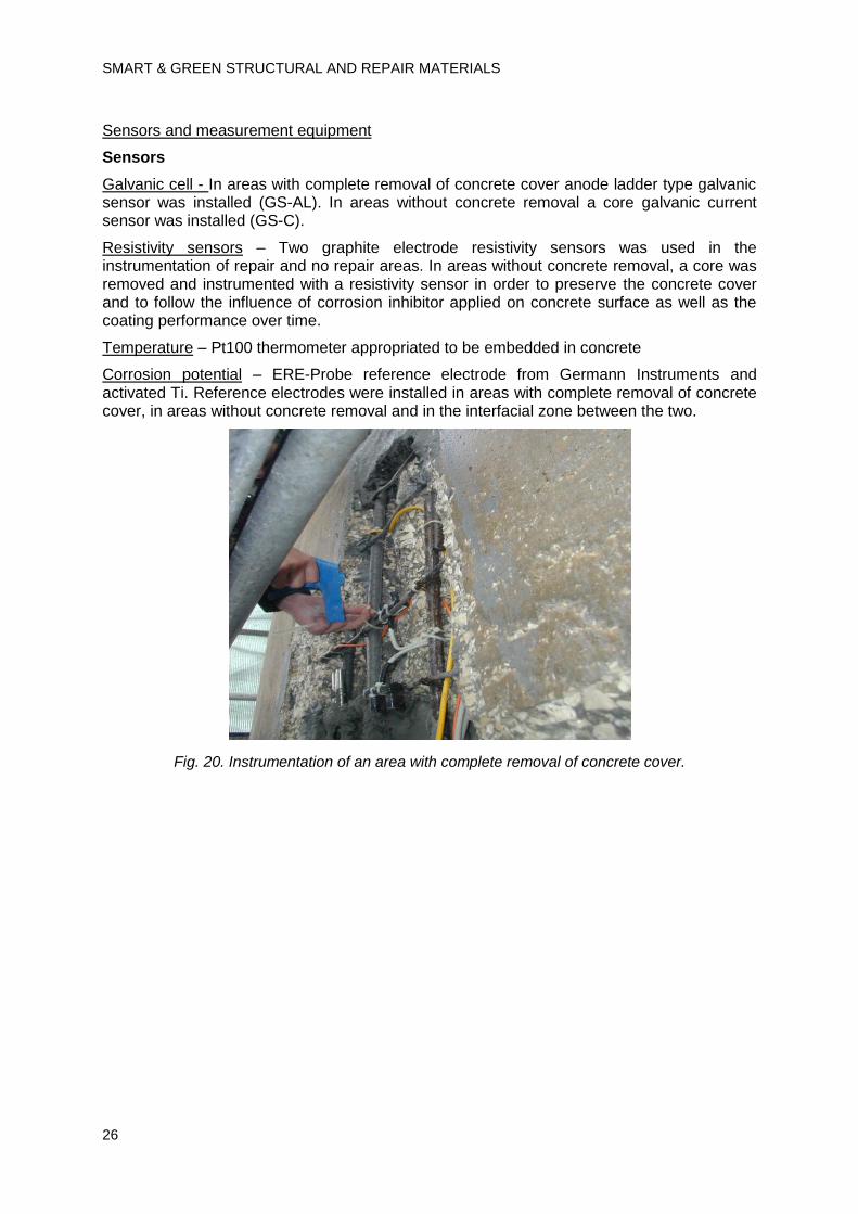
Galvanic cell - In areas with complete removal of concrete cover anode ladder type galvanic sensor was installed (GS-AL). In areas without concrete removal a core galvanic current sensor was installed (GS-C).
Resistivity sensors – Two graphite electrode resistivity sensors was used in the instrumentation of repair and no repair areas. In areas without concrete removal, a core was removed and instrumented with a resistivity sensor in order to preserve the concrete cover and to follow the influence of corrosion inhibitor applied on concrete surface as well as the coating performance over time.
Temperature – Pt100 thermometer appropriated to be embedded in concrete
Corrosion potential – ERE-Probe reference electrode from Germann Instruments and activated Ti. Reference electrodes were installed in areas with complete removal of concrete cover, in areas without concrete removal and in the interfacial zone between the two.
Fig. 20. Instrumentation of an area with complete removal of concrete cover.
CORROSION MONITORING SYSTEMS
27
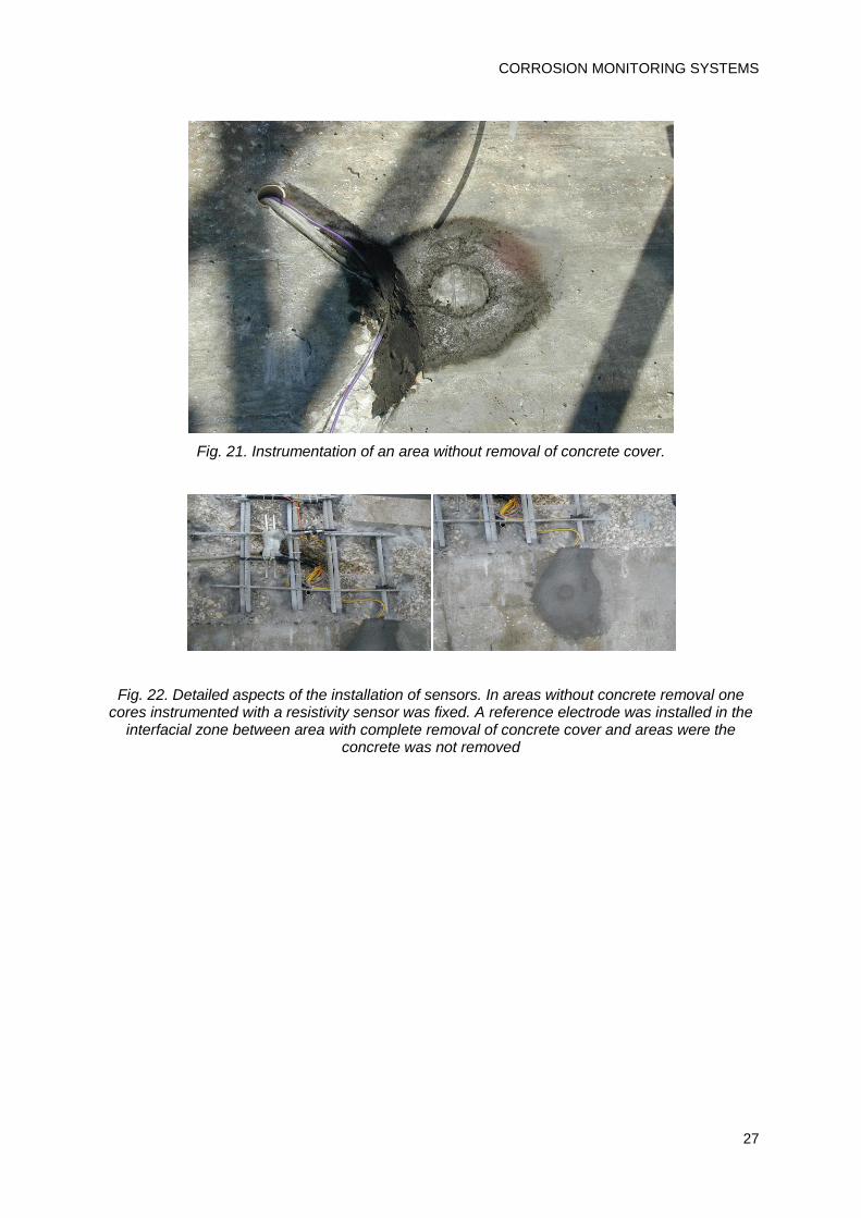
Fig. 21. Instrumentation of an area without removal of concrete cover.
Fig. 22. Detailed aspects of the installation of sensors. In areas without concrete removal one cores instrumented with a resistivity sensor was fixed. A reference electrode was installed in the
interfacial zone between area with complete removal of concrete cover and areas were the concrete was not removed

SMART & GREEN STRUCTURAL AND REPAIR MATERIALS
28
Fig. 23. Cables from the instrumented areas were conducted through external pipes to data acquisition systems installed in polyethylene centralization boxes.
Acquisition data equipment
Datataker 500 automatic acquisition data equipments were installed in centralization boxes. The systems have wireless capability for data transmission.

CORROSION MONITORING SYSTEMS
29
Fig. 24. Aspects of the automatic data acquisition systems installed inside the bridge.
Data management and examples of outcomes
Automatic acquisition of data with daily periodicity was provided.
Examples of outcomes
Corrosion potential (Ecorr)
Measurement of Ecorr showed that reinforcement corrosion do not re-start during the monitoring period.

SMART & GREEN STRUCTURAL AND REPAIR MATERIALS
30
Galvanic Current (Igal)
Galvanic currents measured during the monitoring period present low values, indicative that the reinforcement is not corroding.
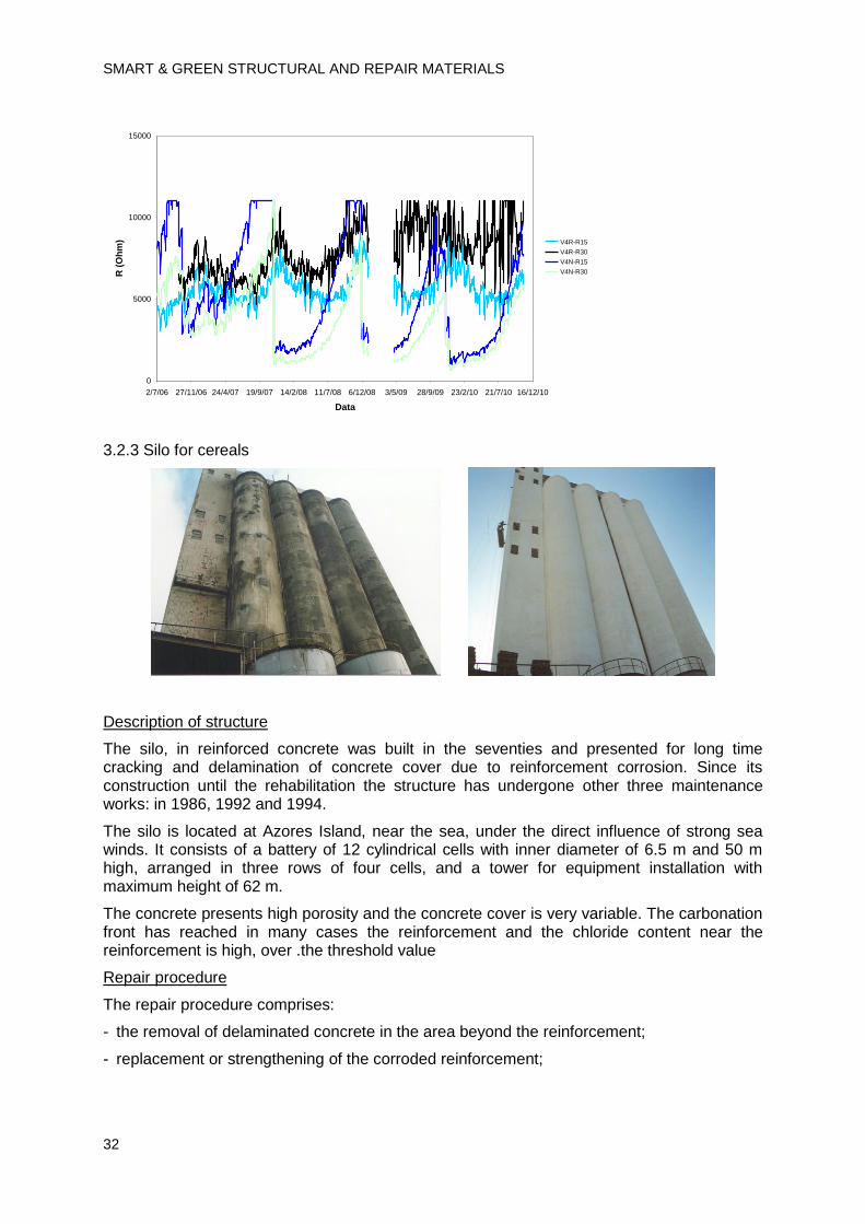
Concrete electrical resistance (R)
Repaired areas
No significant changes of R occurred during the monitoring period. R cyclic variations have been attributed to the variations of environmental parameters, namely temperature, like it can be seen by comparing of the two next figures.
-900
-800
-700
-600
-500
-400
-300
-200
-100
0
2/7/06 27/11/06 24/4/07 19/9/07 14/2/08 11/7/08 6/12/08 3/5/09 28/9/09 23/2/10 21/7/10 16/12/10
Data
Eco
rr (
mV
)V1R-P
V1I-P
V1N-P
V2R-P
V2I-P
V2N-P
V4R-P
V4I-P
V4N-P
-3.0E-05
-2.5E-05
-2.0E-05
-1.5E-05
-1.0E-05
-5.0E-06
0.0E+00
5.0E-06
2/7/06 27/11/06 24/4/07 19/9/07 14/2/08 11/7/08 6/12/08 3/5/09 28/9/09 23/2/10 21/7/10 16/12/10
Data
I gal (A
)
V1R-I15
V1R-I30
V2R-I15
V2R-I30
V4R-I15
V4R-I30
CORROSION MONITORING SYSTEMS
31
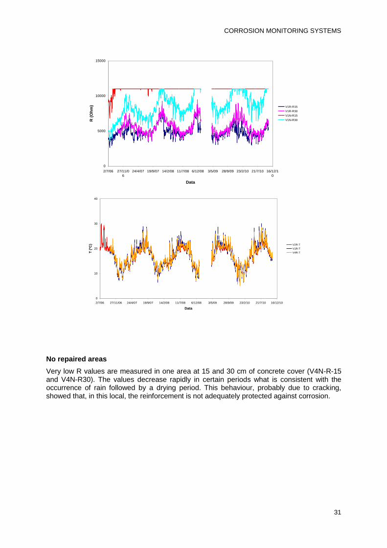
No repaired areas
Very low R values are measured in one area at 15 and 30 cm of concrete cover (V4N-R-15 and V4N-R30). The values decrease rapidly in certain periods what is consistent with the occurrence of rain followed by a drying period. This behaviour, probably due to cracking, showed that, in this local, the reinforcement is not adequately protected against corrosion.
0
5000
10000
15000
2/7/06 27/11/0
6
24/4/07 19/9/07 14/2/08 11/7/08 6/12/08 3/5/09 28/9/09 23/2/10 21/7/10 16/12/1
0
Data
R (
Oh
m) V1R-R15
V1R-R30
V1N-R15
V1N-R30
0
10
20
30
40
2/7/06 27/11/06 24/4/07 19/9/07 14/2/08 11/7/08 6/12/08 3/5/09 28/9/09 23/2/10 21/7/10 16/12/10
Data
T (
ºC) V2R-T
V1R-T
V4R-T
SMART & GREEN STRUCTURAL AND REPAIR MATERIALS
32
3.2.3 Silo for cereals
Description of structure
The silo, in reinforced concrete was built in the seventies and presented for long time cracking and delamination of concrete cover due to reinforcement corrosion. Since its construction until the rehabilitation the structure has undergone other three maintenance works: in 1986, 1992 and 1994.
The silo is located at Azores Island, near the sea, under the direct influence of strong sea winds. It consists of a battery of 12 cylindrical cells with inner diameter of 6.5 m and 50 m high, arranged in three rows of four cells, and a tower for equipment installation with maximum height of 62 m.
The concrete presents high porosity and the concrete cover is very variable. The carbonation front has reached in many cases the reinforcement and the chloride content near the reinforcement is high, over .the threshold value
Repair procedure
The repair procedure comprises:
- the removal of delaminated concrete in the area beyond the reinforcement;
- replacement or strengthening of the corroded reinforcement;
0
5000
10000
15000
2/7/06 27/11/06 24/4/07 19/9/07 14/2/08 11/7/08 6/12/08 3/5/09 28/9/09 23/2/10 21/7/10 16/12/10
Data
R (
Oh
m) V4R-R15
V4R-R30
V4N-R15
V4N-R30
CORROSION MONITORING SYSTEMS
33
- replacement of concrete cover with shotcrete, followed by the application of a migrating corrosion inhibitor and a coating system.
Purpose of instrumentation
In the areas were concrete cover was not removed, the installation of the corrosion monitoring system aims to obtain information about the effect of migrating corrosion inhibitor and coating system to decrease the progress of reinforcement corrosion.
In the areas where the concrete cover was removed, the installation aims to obtain information about the progress of the despassivation front in the concrete cover (carbonation and chlorides ingress).
Sensors and measurement equipment
Location of the instrumentation
A monitoring system consisting of different corrosion sensors embedded in the concrete with an automatic data acquisition was installed.
Sensors were installed in eight areas. The localization of the areas took into account the influence of different exposure conditions, the need to collect data on the effectiveness of the repair method used and to ensure the representativeness of the information collected by the monitoring system.
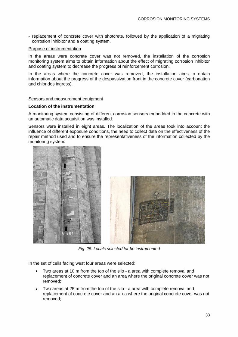
Fig. 25. Locals selected for be instrumented
In the set of cells facing west four areas were selected:
Two areas at 10 m from the top of the silo - a area with complete removal and replacement of concrete cover and an area where the original concrete cover was not removed;
Two areas at 25 m from the top of the silo - a area with complete removal and replacement of concrete cover and an area where the original concrete cover was not removed;
A3 e B3
A4 e B4

SMART & GREEN STRUCTURAL AND REPAIR MATERIALS
34
Overall cell facing south, four areas in the central cell were selected, using the same criterion:
Two areas at 10 m from the top of the silo - a area with complete removal and replacement of concrete cover and an area where the original concrete cover was not removed;
The two areas at 26 m from the top of the silo - a area with complete removal and replacement of concrete cover and an area where the original concrete cover was not removed.
Sensors
Galvanic cell - In areas with complete removal of concrete cover anode ladder type galvanic sensor was installed (GS-AL). In areas without concrete removal a core galvanic current sensor is installed (GS-C).
Resistivity sensors – Two graphite electrode resistivity sensors was used.
Temperature – Pt100 thermometer appropriated to be embedded in concrete
Corrosion potential – ERE-Probe reference electrode from Germann Instruments
Acquisition data equipment
An Argilent datalogger 34970A was installed in the engine room in the top of the silo. The system has wireless capability to data transmission.
Fig. 25. Acquisition data equipment
Data management and examples of outcomes
Automatic acquisition of data with daily periodicity was provided. Results were collected during around 7 years.
Examples of outcomes
Corrosion potential (Ecorr)
Measurement of Ecorr showed that reinforcement corrosion do not start during the monitoring period.

CORROSION MONITORING SYSTEMS
35
Galvanic Current (Igal)
Galvanic currents measured during the monitoring period are low and indicative that the reinforcement is not corroding.
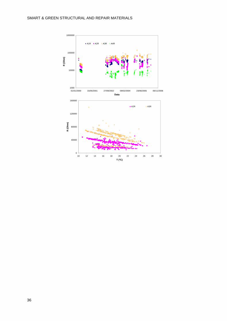
Concrete electrical resistance (R)
No significant changes of R occurred during the monitoring period. R variations have been attributed to the variations of environmental parameters
-0.7
-0.6
-0.5
-0.4
-0.3
-0.2
-0.1
0.0
01/01/2000 15/05/2001 27/09/2002 09/02/2004 23/06/2005 05/11/2006
Data
Ec
orr v
s M
nO
2 (
V)
A1P A2P A3P A4P
-3.0E-05
-2.5E-05
-2.0E-05
-1.5E-05
-1.0E-05
-5.0E-06
0.0E+00
5.0E-06
01/01/2000 15/05/2001 27/09/2002 09/02/2004 23/06/2005 05/11/2006
Data
Igal (A
)
A1M-900 B1M-901A2M-902 B2M-903A3M-904 B3M-905A4M-906 B4M-907
SMART & GREEN STRUCTURAL AND REPAIR MATERIALS
36
1000
10000
100000
1000000
01/01/2000 15/05/2001 27/09/2002 09/02/2004 23/06/2005 05/11/2006
Data
R (
Oh
m)
A1R A2R A3R A4R
0
40000
80000
120000
160000
10 12 14 16 18 20 22 24 26 28 30
T (ºC)
R (
Oh
m)
A2R A3R
CORROSION MONITORING SYSTEMS
37
4 Bibliography
[1] Monitorização da corrosão no betão armado, E. Vaz Pereira, PhD, Faculdade de Ciências da Universidade de Lisboa (2004).
[2] Permanent monitoring of corrosion in pre-tensioned and post-tensioned concrete with embedded sensors, Elsa Vaz Pereira, Manuela Salta, integrado no capítulo “New service approaches” in New Materials, Systems, Methods and Concepts for Prestressed Concrete Structures, ed. R. B. Polder, M. C. Alonso, D. J. Cleland, B. Elsener, E. Provérbio, O. Vennesland, A. Raharinaivo, COST Action 534 Final Report, COST Office (2009).
[3] Embedded sensors for corrosion monitoring of existing reinforced concrete structures, Pereira, E. V., Figueira, R. B., Salta, M. M, Fonseca, I. T. E, Materials Science Forum vol. 587-588, pp. 677-681 (2008).
[4] A galvanic sensor for monitoring the corrosion condition of the concrete reinforcing steel: Relationship between the galvanic and the corrosion currents, Pereira, E. V., Figueira, R. B., Salta, M. M, Fonseca, I. T. E, Sensors, vol. 9, pp 8391-8398 (2009)
[5] Long-term efficiency of two organic corrosion inhibitors for reinforced concrete, Pereira, E. V., Figueira, R. B., Salta, M. M, Fonseca, I. T. E, Materials Science Fórum, vol. 636-637, pp. 1059-1064 (2010).
[6] Monitorização da corrosão em estruturas de betão armado, M. M. Salta, E. Vaz Pereira, JPEE 98 - Jornadas Portuguesas de Engenharia de Estruturas, Lisboa, 1998.
[7] Monitorização da corrosão das armaduras com sensores embebidos, E. Vaz Pereira, M. M. Salta, Colloquia 2001 – Mantenimiento, Conservación e Durabilidade de las Estruturas, ICCET, Madrid, 2001.
[8] Monitorização da corrosão no betão armado, M. M. Salta, E. Vaz Pereira, Seminário “Degradação de estruturas por reacções expansivas de origem interna”, Lisboa, 2001.
[9] Sensores para monitorização da corrosão no betão armado, E. Vaz Pereira, M. M. Salta, I. Fonseca, VI Encontro Ibérico de Electroquímica, Porto, 2001.
[10] Influência da temperatura e humidade relativa na velocidade de corrosão no betão armado, E. Vaz Pereira, M. M. Salta, I. Fonseca, XV Congresso da Sociedade Ibero-Americana de Electroquímica, SIBAE 2002, Évora, 2002 (Ref. nº 5158).
[11] Monitorização permanente da durabilidade de estruturas de betão armado. Métodos existentes e suas limitações, E. V. Pereira, M. M. Salta, 4as Jornadas Portuguesas de Engenharia de Estruturas JPEE2006, LNEC, 2006.
[12] Development of resistivity sensors for monitoring concrete structures, J. T. Santos, E. V. Pereira, M. M. Salta, I. T: Fonseca, A. C. Amorim, 57th Annual

SMART & GREEN STRUCTURAL AND REPAIR MATERIALS
38
Meeting of the International Society of Electrochemistry, S9-P-17, Edinburgh, 2006.
[13] Corrosion inhibitors for reinforced concrete: long-term tests, E. Vaz Pereira, R. B. Figueira, M. M. Salta, I. T. E. Fonseca, XIV Encontro da Sociedade Portuguesa de Electroquímica, X Iberic Meeting of Electrochemistry, Coimbra, 2007.
[14] Embedded sensors for corrosion monitoring of existing reinforced concrete structures, A. C. Amorim, E. V. Pereira, M. M. Salta, I. T. Fonseca, Materiais 2007, XIII Conference of Sociedade Portuguesa de Materiais e IV International Materials Symposium, Porto, 2007.
[15] Novos sistemas de monitorização da durabilidade em estruturas de betão armado, R.B. Figueira, E.V. Pereira, M.M. Salta, A.P. Silveira, I.T.E. Fonseca, Encontro “Dia do Bolseiro”, Lisboa, 2007.
[16] Galvanic sensors for monitoring the corrosion in solutions simulating concrete conditions in agressive environment, R.B. Figueira, E.V. Pereira, M.M. Salta, I.T.E. Fonseca, 59th Annual Meeting of the International Society of Electrochemistry, Sevilha, 2008.
[17] Instalação de um sistema de monitorização da corrosão numa ponte cais de aprestamento dos estaleiros da Lisnave em Setúbal, M. M. Salta, E. Vaz Pereira, Relatório LNEC 325/98 (1998)
[18] Observação do comportamento à corrosão do betão armado na obra de ampliação do aeroporto do Funchal, M. M. Salta, E. Vaz Pereira, Nota Técnica LNEC 2/99 – DMC/NQ (1999).
[19] Instalação de um sistema de monitorização da corrosão num silo em S. Miguel, Açores, E. Vaz Pereira, M. M. Salta, Relatório LNEC 169/00 – DMC/NQ (2000).
[20] Monitorização da corrosão na estrutura principal da 2ª fase da ampliação do Aeroporto do Funchal, E. Vaz Pereira, M. M. Salta, Relatório LNEC 325/02 (2002).
[21] Instalação de um sistema de monitorização da corrosão na ponte Infante D. Henrique, E. Vaz Pereira, Relatório LNEC 309/03 (2003).
[22] Instalação de um sistema de monitorização da corrosão na Ponte da Figueira da Foz, E. Vaz Pereira, N. Garcia, Relatório LNEC 294/06 – NMM (2006).
[23] Monitorização da corrosão na ponte da Figueira da Foz. Resultados do acompanhamento em 2007, E. Vaz Pereira, N. Garcia, Relatório LNEC 380/2007 – NMM (2007).
[24] Concepção e instalação de um sistema de monitorização da corrosão na Ponte da Barra, E. Vaz Pereira, N. Garcia, Relatório LNEC 58/2009 – NMM (2009).
[25] Monitorização da corrosão na ponte da Figueira da Foz. Resultados do acompanhamento em 2008, E. Vaz Pereira, N. Garcia, Relatório LNEC 61/2009 – NMM (2009).
CORROSION MONITORING SYSTEMS
39
[26] Monitorização da corrosão na estrutura principal da 2ª fase da ampliação do Aeroporto do Funchal. Resultados das leituras efectuadas até Abril de 2008. E. Vaz Pereira, N. Garcia, Relatório LNEC 121/2009 (2009).
[27] Ponte da Figueira da Foz. Acompanhamento do sistema de monitorização da corrosão em 2009, E. Vaz Pereira, N. Garcia, Relatório LNEC 397/2009 – NMM (2009).
[28] Monitorização da corrosão na Ponte da Barra. Resultados do acompanhamento em 2009, E. Vaz Pereira, N. Garcia, Relatório LNEC 398/2009 – NMM (2009).
[29] Rehabilitation of the Figueira da Foz Bridge, A. Rito, J. Appleton, IABMAS06, Third International Conference on Bridge Maintenance, Safety and Management, July 16-19, 2006, Porto-Portugal.
[30] Innovative and contemporary Porto Bridges, P. J. S: Cruz, J. M. Lopes Cordeiro, Practice periodical on structural design and construction, ASCE, February 2004, 26.
DURATINET PARTNERS
PORTUGALLaboratório Nacional de Engenharia Civil, I.P. (LNEC)Estradas de Portugal, SA (EP)REFER, E.P.TEIXEIRA DUARTE – Engenharia e Construções, S.A.Administração do Porto de Lisboa (APL)Fundo para o Desenvolvimento das Ciências da Construção (FUNDCIC)
FRANCEInstitut français des sciences et technologies des transports, de l’aménagement et des réseaux (IFSTTAR)Université de BordeauxUniversité de NantesUniversité de La RochelleConseil General de la Charente-Maritime (CG-17)
IRELANDDublin University- Trinity College (TCD)National Roads Authority (NRA)
SPAINUniversidade de Vigo (UV)Porto de VigoXunta da Galiza
UNITED KINGDOMQueen’s University Belfast (QUB)
TECHNICAL REPORT
TR 6 .1REPAIR AND GREEN CONCRETE
smart & green • structural and repair materials