pulsed plasma thruster development
TRANSCRIPT
PULSED PLASMA THRUSTER DEVELOPMENT Rodrigo Intini Marques Laboratório Associado de Combustão e Propulsão, INPE Rodovia Presidente Dutra KM 40, Cachoeira Paulista, SP, 12630-000, Brazil e-mail: [email protected] Fernando de Souza Costa Laboratório Associado de Combustão e Propulsão, INPE Rodovia Presidente Dutra KM 40, Cachoeira Paulista, SP, 12630-000, Brazil e-mail: [email protected] Abstract. This work describes the preliminary design and the initial development of a pulsed plasma thruster (PPT) to test different fuels, geometries, energies of discharge, voltages and frequencies. A PPT is an electric thruster used for attitude control and orbit correction of satellites and space probes. It uses a high-voltage discharge applied to the surface of a solid propellant bar. The propellant is ablated, ionized and accelerated by a combination of electromagnetic forces (Lorenz Force) and thermal expansion to create usable thrust. The PPT comprises a control circuit, a direct current converter (DC-DC) and a discharge chamber. The discharge chamber chosen includes a solid annular Teflon rod as fuel and two concentric cylindrical electrodes of copper. Three PPT versions were developed. The first version used an 8µF capacitor charged with 24 V yielding 2.304 mJ per pulse with a 10 kV discharge. The second version had an 4 µF capacitor loaded with 169.7 V yielding 57.6 mJ per pulse with a 18 kV discharge. It was tested in a vacuum chamber for 7.5 hours, generating 1,616,400 pulses at 60 Hz with total mass variation of 45.1 mg, with 0.028 µg ablated per pulse and a calculated impulse bit of 1.12 µNs. The third version under development allows operation at different frequencies 0.1-10 Hz, pulse energies 0.1-10 J and discharge voltages 10-40 kV. This version will permit the validation of thruster components for use on different missions. Keywords. advanced propulsion, plasma thruster, PPT, satellite, space probe.
1. Introduction
Electrical propulsion systems allow the transport of larger payloads or longer lifetimes than chemical systems. In general, electrical thrusters yield very low thrust levels (< 1 mN) and high specific impulses (> 1000 s), therefore they are appropriate for attitude control or orbit correction of satellites and use in space probes (Costa and Carvalho-Jr, 1998).
The pulsed plasma thruster (PPT) was the first electric thruster to be used in space, when the Zond 2 spacecraft was launched on November 30th, 1964, from Baikonur in the Soviet Union, using a system of PPT’s for attitude control. Since then many PPT thrusters have flown on various space missions (Burton and Turchi, 1998).
Palumbo and Guman (1976) pointed out that PPTs have several advantages compared to other propulsion sytems: zero preheating time; zero power consumption at standby mode; low failure propensity; no forces or torques when out of operation; scalable according to performance requirements; can be used in satellites stabilized by rotation or with three axis stabilization; no tanks, feed lines, seals or mechanic valves; measurement of fuel consumption is easy; operates at zero gravity; supports cryogenic temperatures; compatible with vacuum; non-corrosive, non-toxic fuel; storable for long periods; not affected by rapid temperature changes or large accelerations; discrete impulse compatible with digital logic; variable thrust level; performance compatible with attitude control and orbit correction; operates under a large range of ambient conditions; better control of thrust vector.
Pulsed plasma thrusters work with very short pulse widths on the order of tens of microseconds. As a result, the minimum amount of momentum that can be imparted to a spacecraft in one pulse, called impulse bit (Ibit), can be quite small, yielding very accurate orbit correction and attitude maneuvers.
In order to fire a PPT, a capacitor is discharged creating a large electric potential across the space between the electrodes. This potential causes a surface breakdown on the face of a solid bar of propellant (usually Teflon), ablating it and allowing an arc to pass through the outer, gaseous layer, ionizing it. Therefore, there is a Lorenz force (I×B) acting on the ions upstream of the arc that accelerates them downstream. In addition, there is a gas dynamic effect caused by the heating of the ablated Teflon by the arc.
The efficiency of a pulsed thruster, ηt, is given by:
2
02bit
tshot
Im E
η = (1)
where Ibit is the impulse bit (Ns), E0 is the energy stored in the capacitor bank (J), and mshot is the mass ablated per shot (kg) (Reichbach et al, 2001).
An equation yielding the maximum current, Imax (A), demanded from the spacecraft power supply is

0 maxmax
sc t
E FI
V η= (2)
where Fmax is the maximum frequency (Hz) and Vsc is the voltage (V) of the spacecraft’s power supply.
The maximum average power input, Pmax (W), to the thruster is given by
max 0 maxP E F= (3) Figure (1) shows the relations between the PPT parameters and is quite useful in the development process. In Fig.
(1), mcap is the capacitor mass (kg), mdc-dc is the mass (kg) of the DC-DC converter , mprop is the total mass (kg) of propellant, ∆V is the characteristic velocity (m/s) of the space mission, dLshot is the length (m) of the fuel rod that is ablated per pulse and Aprop is the cross sectional area (m2) of the propellant rod.
Figure 1. Interdependency between PPT parameters (Reichbach et al, 2001) adapted.
Several studies have been made on the performance and development of pulsed plasma thrusters. Guman and Nathanson (1970) described the design, construction and flight qualification of a PPT system for a synchronous orbit satellite. Vondra, Thomassen and Solbes (1971) described the PPTs used in the LES-6 satellite. Thomassen and Vondra (1972) studied exhaust velocities of PPTs. Vondra and Thomassen (1972) described 2 J and 20 J PPT’s with a new feed system. Solbes and Vondra (1973) studied the over-all operating characteristics of a parallel rail solid fuel pulsed thruster. Palumbo and Guman (1976) studied the effects of propellant and electrode geometry. Turchi (1984) described a strategy for electric propulsion development using PPTs. Rudikov et al. (1995) described a PPT for a geostationary satellite. Spanjers et al. (1998) studied the effect of the propellant temperature on PPT efficiency. Burton and Turchi (1998) presented a review of development and application of PPT’s in the previous 35 years. Gulczinski III et al. (2000) described a micro-pulsed plasma thruster (micro-PPT), a simplified version of the PPT, for use in small satellites (25 kg class and 10 µNs impulse bits). Boyd et al. (2000) modeled the plasma generation to the plume far field of a PPT. Reichbach et al. (2001) studied several advanced propulsion systems for satellite applications and presented a comparison between the PPT and other thrusters for flying formation satellites.
This work describes the preliminary design and the initial development of three versions of a PPT made at the Combustion and Propulsion Laboratory of INPE. The primary objective is to develop a laboratory PPT to test different fuels, geometries, energies of discharge, voltages and frequencies. 2. The PPT Design
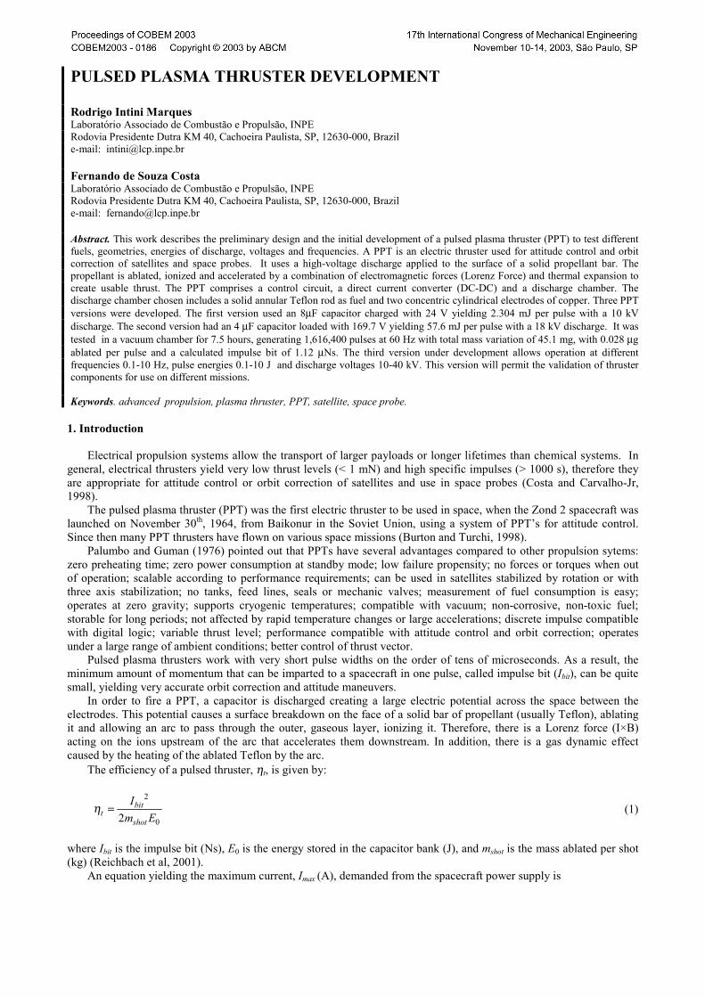
The PPT design and development was divided in three parts: i) discharge chamber; ii) control circuit; and iii) DC-DC converter. A block diagram of the thruster is showed in Fig. (2).
The discharge chamber includes the solid fuel and the electrodes. The control circuit synchronizes the loading and discharging of the capacitor’s bank at a specified frequency. The DC-DC converter increases the low voltage available in the spacecraft to a high voltage by using a capacitor bank and an autotransformer.
In the discharge chamber plasma is produced and accelerated by the electromagnetic forces and thermal expansion. In this work it was chosen a compact cylindrical design, with an annular Teflon rod placed between two concentric cylindrical copper electrodes. This geometry is usually applied to micro-PPT thrusters, however, since large discharge energies are used in these prototypes, the expression micro-PPT is not applied here.
E0 mcap
Ibit
Isp
Pmax mdc-dc
Imax Fmax
mshot mprop
Aprop dLshot ∆V
The control circuit is an interface between the thruster and the spacecraft, receiving three basic commands from the
board computer of the spacecraft: i) frequency of operation; ii) start; and iii) stop. The control circuit provides all signals to the DC-DC converter in order to execute the commands received.
The DC-DC converter converts the low voltage available in the spacecraft, usually 28 V, to the higher voltage required in the discharge chamber (10 - 40 kV).
Figure 2. Thruster block diagram
3. The PPT design description 3.1 Discharge Chamber
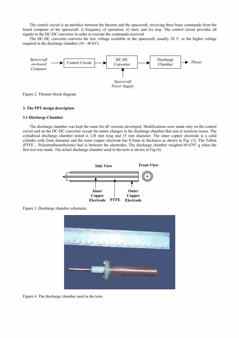
The discharge chamber was kept the same for all versions developed. Modifications were made only on the control circuit and on the DC-DC converter except for minor changes in the discharge chamber that aim at isolation issues. The cylindrical discharge chamber tested is 128 mm long and 15 mm diameter. The inner copper electrode is a solid cylinder with 2mm diameter and the outer copper electrode has 0.5mm in thickness as shown in Fig. (3). The Teflon (PTFE – Polytetrafluorethylene) fuel is between the electrodes. The discharge chamber weighed 69.4707 g when the first test was made. The actual discharge chamber used in the tests is shown in Fig.(4).
Figure 3. Discharge chamber schematic.
Figure 4. The discharge chamber used in the tests.
Thrust DC-DC Converter Control Circuit
Spacecraft Power Supply
Spacecraft on-board Computer
Discharge Chamber
Front View Side View
PTFE
Outer Copper
Electrode
Inner Copper
Electrode
3.2 The DC-DC converter
Many approaches were attempted to convert the available spacecraft voltages to the much higher voltage required to reach the dielectric breakdown voltage of the fuel bar. Nevertheless the DC-DC converter principles remain the same for all versions. A bank of capacitors is charged with a relatively low voltage and discharged through an autotransformer that, in turn, raises the voltage to the appropriate values.
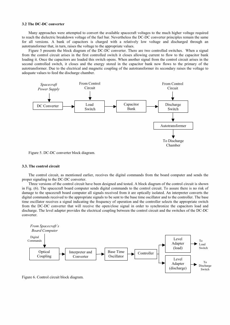
Figure 5 presents the block diagram of the DC-DC converter. There are two controlled switches. When a signal from the control circuit arises in the first controlled switch it closes allowing current to flow to the capacitor bank loading it. Once the capacitors are loaded this switch opens. When another signal from the control circuit arises in the second controlled switch, it closes and the energy stored in the capacitor bank now flows to the primary of the autotransformer. Due to the electrical and magnetic coupling of the autotransformer its secondary raises the voltage to adequate values to feed the discharge chamber.
Figure 5. DC-DC converter block diagram. 3.3. The control circuit
The control circuit, as mentioned earlier, receives the digital commands from the board computer and sends the proper signaling to the DC-DC converter.
Three versions of the control circuit have been designed and tested. A block diagram of the control circuit is shown in Fig. (6). The spacecraft board computer sends digital commands to the control circuit. To assure there is no risk of damage to the spacecraft board computer all signals received from it are optically isolated. An interpreter converts the digital commands received to the appropriate signals to be sent to the base time oscillator and to the controller. The base time oscillator receives a signal indicating the frequency of operation and the controller selects the appropriate switch from the DC-DC converter that will receive the open/close signal in order to synchronize the capacitors load and discharge. The level adapter provides the electrical coupling between the control circuit and the switches of the DC-DC converter. Figure 6. Control circuit block diagram.
Capacitor Bank
Load Switch
Spacecraft Power Supply
DC Converter Discharge Switch
Autotransformer
To Discharge Chamber
From Control Circuit
From Control Circuit
From Spacecraft´s Board Computer
Digital Commands
Optical Coupling
Interpreter and Converter
Base Time Oscillator
Level Adapter
(discharge)
To Load Switch
Controller
Level Adapter (load)
To Discharge
Switch
4. Tested Versions 4.1 First Version
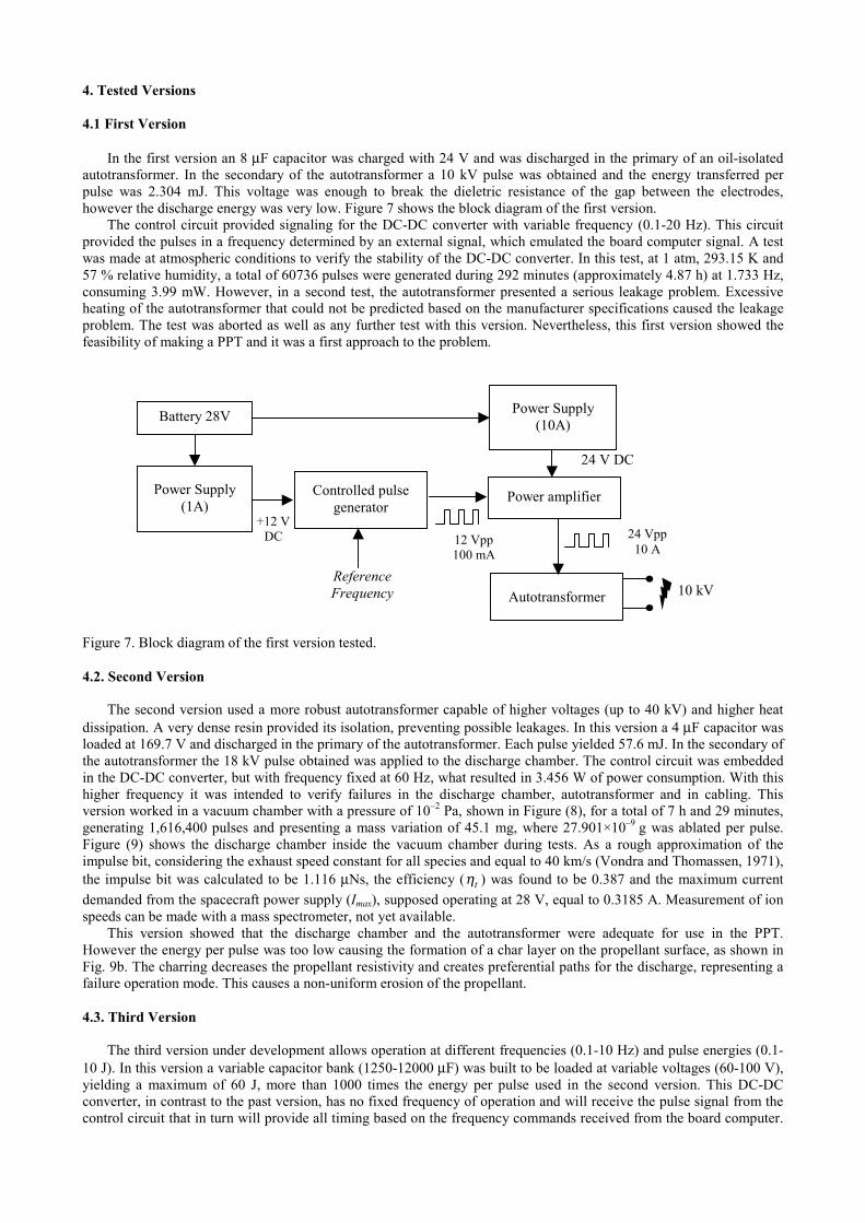
In the first version an 8 µF capacitor was charged with 24 V and was discharged in the primary of an oil-isolated autotransformer. In the secondary of the autotransformer a 10 kV pulse was obtained and the energy transferred per pulse was 2.304 mJ. This voltage was enough to break the dieletric resistance of the gap between the electrodes, however the discharge energy was very low. Figure 7 shows the block diagram of the first version.
The control circuit provided signaling for the DC-DC converter with variable frequency (0.1-20 Hz). This circuit provided the pulses in a frequency determined by an external signal, which emulated the board computer signal. A test was made at atmospheric conditions to verify the stability of the DC-DC converter. In this test, at 1 atm, 293.15 K and 57 % relative humidity, a total of 60736 pulses were generated during 292 minutes (approximately 4.87 h) at 1.733 Hz, consuming 3.99 mW. However, in a second test, the autotransformer presented a serious leakage problem. Excessive heating of the autotransformer that could not be predicted based on the manufacturer specifications caused the leakage problem. The test was aborted as well as any further test with this version. Nevertheless, this first version showed the feasibility of making a PPT and it was a first approach to the problem. Figure 7. Block diagram of the first version tested. 4.2. Second Version
The second version used a more robust autotransformer capable of higher voltages (up to 40 kV) and higher heat
dissipation. A very dense resin provided its isolation, preventing possible leakages. In this version a 4 µF capacitor was loaded at 169.7 V and discharged in the primary of the autotransformer. Each pulse yielded 57.6 mJ. In the secondary of the autotransformer the 18 kV pulse obtained was applied to the discharge chamber. The control circuit was embedded in the DC-DC converter, but with frequency fixed at 60 Hz, what resulted in 3.456 W of power consumption. With this higher frequency it was intended to verify failures in the discharge chamber, autotransformer and in cabling. This version worked in a vacuum chamber with a pressure of 10–2 Pa, shown in Figure (8), for a total of 7 h and 29 minutes, generating 1,616,400 pulses and presenting a mass variation of 45.1 mg, where 27.901×10⁻⁹ g was ablated per pulse. Figure (9) shows the discharge chamber inside the vacuum chamber during tests. As a rough approximation of the impulse bit, considering the exhaust speed constant for all species and equal to 40 km/s (Vondra and Thomassen, 1971), the impulse bit was calculated to be 1.116 µNs, the efficiency ( tη ) was found to be 0.387 and the maximum current demanded from the spacecraft power supply (Imax), supposed operating at 28 V, equal to 0.3185 A. Measurement of ion speeds can be made with a mass spectrometer, not yet available.
This version showed that the discharge chamber and the autotransformer were adequate for use in the PPT. However the energy per pulse was too low causing the formation of a char layer on the propellant surface, as shown in Fig. 9b. The charring decreases the propellant resistivity and creates preferential paths for the discharge, representing a failure operation mode. This causes a non-uniform erosion of the propellant. 4.3. Third Version
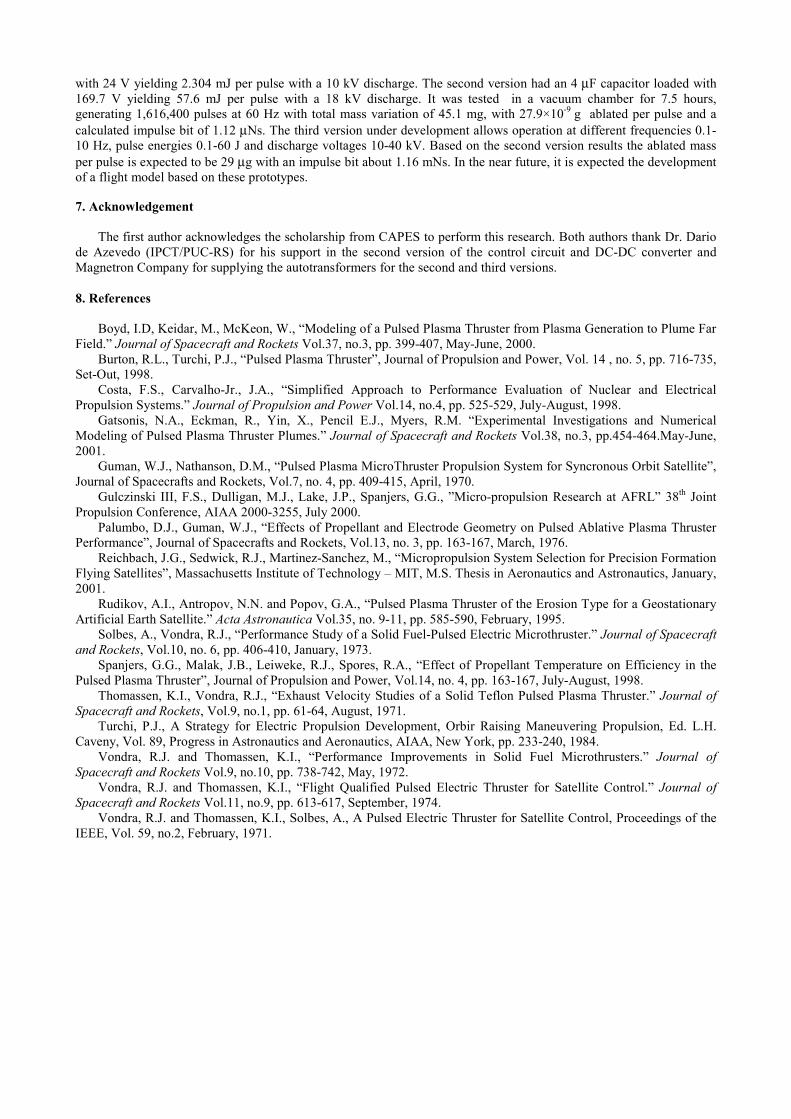
The third version under development allows operation at different frequencies (0.1-10 Hz) and pulse energies (0.1-
10 J). In this version a variable capacitor bank (1250-12000 µF) was built to be loaded at variable voltages (60-100 V), yielding a maximum of 60 J, more than 1000 times the energy per pulse used in the second version. This DC-DC converter, in contrast to the past version, has no fixed frequency of operation and will receive the pulse signal from the control circuit that in turn will provide all timing based on the frequency commands received from the board computer.
Power Supply (1A)
Controlled pulse generator
Power Supply (10A)
Autotransformer
+12 V DC
Power amplifier
Battery 28V
24 V DC
12 Vpp 100 mA
24 Vpp 10 A
10 kV Reference Frequency

In order to evaluate the DC-DC converter circuit alone an external signal generator optically insulated is being used to emulate the board computer. The main problem with this version is the power of the discharge, which with the estimated discharge time of 1µs should yield approximately 60 MW of instantaneous power, what means high dV/dt and di/dt that makes harder to specify the components responsible for the switching. Many approaches were tested, including transistors and electromechanical relays. Transistors were too slow for this application, yielding poor di/dt. Electromechanical relays presented sparking problems which caused serious damage to the relay contacts and eventually short-circuited the DC-DC converter, destructing the autotransformer. An insulated gate bipolar transistor (IGBT) was tested and approved for the loading sequence of the DC-DC converter. The discharge sequence is being tested with a SCR (Silicon Controlled Rectifier) satisfactorily.
Mass consumption test are under way. Considering the mass ablated per joule rate of 0.484 µg/J from the earlier version it is estimated that 29 µg will be ablated per pulse in this new version. If it is again considered an expected exhaust speed constant for all species and equal to 40 km/s, then the expected impulse bit would be 1.16 mNs.
Figure 8. The vacuum chamber used in the tests at INPE-LCP.
Figure 9. The discharge chamber inside the vacuum chamber during a test.
Figure 9 shows the DC-DC converter and integrated control circuit used the second version and the laboratory capacitor bank for the third version.
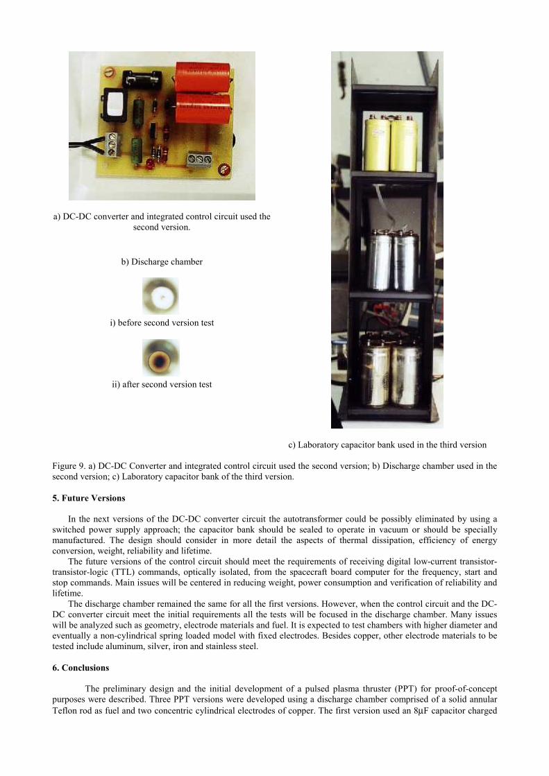
a) DC-DC converter and integrated control circuit used the second version.
b) Discharge chamber
i) before second version test
ii) after second version test
c) Laboratory capacitor bank used in the third version Figure 9. a) DC-DC Converter and integrated control circuit used the second version; b) Discharge chamber used in the second version; c) Laboratory capacitor bank of the third version. 5. Future Versions
In the next versions of the DC-DC converter circuit the autotransformer could be possibly eliminated by using a switched power supply approach; the capacitor bank should be sealed to operate in vacuum or should be specially manufactured. The design should consider in more detail the aspects of thermal dissipation, efficiency of energy conversion, weight, reliability and lifetime.
The future versions of the control circuit should meet the requirements of receiving digital low-current transistor-transistor-logic (TTL) commands, optically isolated, from the spacecraft board computer for the frequency, start and stop commands. Main issues will be centered in reducing weight, power consumption and verification of reliability and lifetime.
The discharge chamber remained the same for all the first versions. However, when the control circuit and the DC-DC converter circuit meet the initial requirements all the tests will be focused in the discharge chamber. Many issues will be analyzed such as geometry, electrode materials and fuel. It is expected to test chambers with higher diameter and eventually a non-cylindrical spring loaded model with fixed electrodes. Besides copper, other electrode materials to be tested include aluminum, silver, iron and stainless steel. 6. Conclusions
The preliminary design and the initial development of a pulsed plasma thruster (PPT) for proof-of-concept purposes were described. Three PPT versions were developed using a discharge chamber comprised of a solid annular Teflon rod as fuel and two concentric cylindrical electrodes of copper. The first version used an 8µF capacitor charged
with 24 V yielding 2.304 mJ per pulse with a 10 kV discharge. The second version had an 4 µF capacitor loaded with 169.7 V yielding 57.6 mJ per pulse with a 18 kV discharge. It was tested in a vacuum chamber for 7.5 hours, generating 1,616,400 pulses at 60 Hz with total mass variation of 45.1 mg, with 27.9×10⁻⁹
g ablated per pulse and a calculated impulse bit of 1.12 µNs. The third version under development allows operation at different frequencies 0.1-10 Hz, pulse energies 0.1-60 J and discharge voltages 10-40 kV. Based on the second version results the ablated mass per pulse is expected to be 29 µg with an impulse bit about 1.16 mNs. In the near future, it is expected the development of a flight model based on these prototypes.
7. Acknowledgement
The first author acknowledges the scholarship from CAPES to perform this research. Both authors thank Dr. Dario de Azevedo (IPCT/PUC-RS) for his support in the second version of the control circuit and DC-DC converter and Magnetron Company for supplying the autotransformers for the second and third versions. 8. References
Boyd, I.D, Keidar, M., McKeon, W., “Modeling of a Pulsed Plasma Thruster from Plasma Generation to Plume Far Field.” Journal of Spacecraft and Rockets Vol.37, no.3, pp. 399-407, May-June, 2000.
Burton, R.L., Turchi, P.J., “Pulsed Plasma Thruster”, Journal of Propulsion and Power, Vol. 14 , no. 5, pp. 716-735, Set-Out, 1998.
Costa, F.S., Carvalho-Jr., J.A., “Simplified Approach to Performance Evaluation of Nuclear and Electrical Propulsion Systems.” Journal of Propulsion and Power Vol.14, no.4, pp. 525-529, July-August, 1998.
Gatsonis, N.A., Eckman, R., Yin, X., Pencil E.J., Myers, R.M. “Experimental Investigations and Numerical Modeling of Pulsed Plasma Thruster Plumes.” Journal of Spacecraft and Rockets Vol.38, no.3, pp.454-464.May-June, 2001.
Guman, W.J., Nathanson, D.M., “Pulsed Plasma MicroThruster Propulsion System for Syncronous Orbit Satellite”, Journal of Spacecrafts and Rockets, Vol.7, no. 4, pp. 409-415, April, 1970.
Gulczinski III, F.S., Dulligan, M.J., Lake, J.P., Spanjers, G.G., ”Micro-propulsion Research at AFRL” 38th Joint Propulsion Conference, AIAA 2000-3255, July 2000.
Palumbo, D.J., Guman, W.J., “Effects of Propellant and Electrode Geometry on Pulsed Ablative Plasma Thruster Performance”, Journal of Spacecrafts and Rockets, Vol.13, no. 3, pp. 163-167, March, 1976.
Reichbach, J.G., Sedwick, R.J., Martinez-Sanchez, M., “Micropropulsion System Selection for Precision Formation Flying Satellites”, Massachusetts Institute of Technology – MIT, M.S. Thesis in Aeronautics and Astronautics, January, 2001.
Rudikov, A.I., Antropov, N.N. and Popov, G.A., “Pulsed Plasma Thruster of the Erosion Type for a Geostationary Artificial Earth Satellite.” Acta Astronautica Vol.35, no. 9-11, pp. 585-590, February, 1995.
Solbes, A., Vondra, R.J., “Performance Study of a Solid Fuel-Pulsed Electric Microthruster.” Journal of Spacecraft and Rockets, Vol.10, no. 6, pp. 406-410, January, 1973.
Spanjers, G.G., Malak, J.B., Leiweke, R.J., Spores, R.A., “Effect of Propellant Temperature on Efficiency in the Pulsed Plasma Thruster”, Journal of Propulsion and Power, Vol.14, no. 4, pp. 163-167, July-August, 1998.
Thomassen, K.I., Vondra, R.J., “Exhaust Velocity Studies of a Solid Teflon Pulsed Plasma Thruster.” Journal of Spacecraft and Rockets, Vol.9, no.1, pp. 61-64, August, 1971.
Turchi, P.J., A Strategy for Electric Propulsion Development, Orbir Raising Maneuvering Propulsion, Ed. L.H. Caveny, Vol. 89, Progress in Astronautics and Aeronautics, AIAA, New York, pp. 233-240, 1984.
Vondra, R.J. and Thomassen, K.I., “Performance Improvements in Solid Fuel Microthrusters.” Journal of Spacecraft and Rockets Vol.9, no.10, pp. 738-742, May, 1972.
Vondra, R.J. and Thomassen, K.I., “Flight Qualified Pulsed Electric Thruster for Satellite Control.” Journal of Spacecraft and Rockets Vol.11, no.9, pp. 613-617, September, 1974.
Vondra, R.J. and Thomassen, K.I., Solbes, A., A Pulsed Electric Thruster for Satellite Control, Proceedings of the IEEE, Vol. 59, no.2, February, 1971.