manual de instruções sensor 3d - ifm.com · instruções de segurança 2.1 geral ... os dados de...
TRANSCRIPT

Manual de instruções Sensor 3D
O3D300 O3D302 O3D310 O3D312
7063
98 /
07
03 /
2018
PT

Sensor 3D
2
Conteúdo1. Nota prévia 4
1.1 Símbolos utilizados. . . . . . . . . . . . . . . . . . . . . . . . . . . . . . . . . . . . . . . . . . . . . . . . . . . . . . . . . . . . .41.2 Advertências utilizadas . . . . . . . . . . . . . . . . . . . . . . . . . . . . . . . . . . . . . . . . . . . . . . . . . . . . . . . . . .41.3 Open source information . . . . . . . . . . . . . . . . . . . . . . . . . . . . . . . . . . . . . . . . . . . . . . . . . . . . . . . .5
2. Instruções de segurança . . . . . . . . . . . . . . . . . . . . . . . . . . . . . . . . . . . . . . . . . . . . . . . . . . . . . . . . . . . .62.1 Geral . . . . . . . . . . . . . . . . . . . . . . . . . . . . . . . . . . . . . . . . . . . . . . . . . . . . . . . . . . . . . . . . . . . . . .62.2 Grupo-alvo . . . . . . . . . . . . . . . . . . . . . . . . . . . . . . . . . . . . . . . . . . . . . . . . . . . . . . . . . . . . . . . . . . .62.3 Conexão elétrica. . . . . . . . . . . . . . . . . . . . . . . . . . . . . . . . . . . . . . . . . . . . . . . . . . . . . . . . . . . . . . .62.4 Alterações no equipamento . . . . . . . . . . . . . . . . . . . . . . . . . . . . . . . . . . . . . . . . . . . . . . . . . . . . . .6
3. Utilização adequada . . . . . . . . . . . . . . . . . . . . . . . . . . . . . . . . . . . . . . . . . . . . . . . . . . . . . . . . . . . . . . .7
4. Material incluído. . . . . . . . . . . . . . . . . . . . . . . . . . . . . . . . . . . . . . . . . . . . . . . . . . . . . . . . . . . . . . . . . . .7
5. Acessórios . . . . . . . . . . . . . . . . . . . . . . . . . . . . . . . . . . . . . . . . . . . . . . . . . . . . . . . . . . . . . . . . . . . . . .7
6. Instalação . . . . . . . . . . . . . . . . . . . . . . . . . . . . . . . . . . . . . . . . . . . . . . . . . . . . . . . . . . . . . . . . . . . . . .86.1 Escolher o local da instalação . . . . . . . . . . . . . . . . . . . . . . . . . . . . . . . . . . . . . . . . . . . . . . . . . . . .86.2 Preparar o equipamento para ser colocado em funcionamento. . . . . . . . . . . . . . . . . . . . . . . . . . .9
6.2.1 Limites de advertência típicos para O3D300 / O3D302 . . . . . . . . . . . . . . . . . . . . . . . . . . . . .96.2.2 Limites de advertência típicos para O3D310 / O3D312 . . . . . . . . . . . . . . . . . . . . . . . . . . . .106.2.3 Redução da temperatura da superfície . . . . . . . . . . . . . . . . . . . . . . . . . . . . . . . . . . . . . . . .10
6.3 Instalar o equipamento . . . . . . . . . . . . . . . . . . . . . . . . . . . . . . . . . . . . . . . . . . . . . . . . . . . . . . . . . 116.4 Acessórios de instalação . . . . . . . . . . . . . . . . . . . . . . . . . . . . . . . . . . . . . . . . . . . . . . . . . . . . . . . 11
7. Conexão elétrica . . . . . . . . . . . . . . . . . . . . . . . . . . . . . . . . . . . . . . . . . . . . . . . . . . . . . . . . . . . . . . . . .127.1 Atribuição da conexão . . . . . . . . . . . . . . . . . . . . . . . . . . . . . . . . . . . . . . . . . . . . . . . . . . . . . . . . .12
7.1.1 Pino 1 / 3 (24 V / GND). . . . . . . . . . . . . . . . . . . . . . . . . . . . . . . . . . . . . . . . . . . . . . . . . . . . .137.1.2 Pino 2 (entrada do trigger) . . . . . . . . . . . . . . . . . . . . . . . . . . . . . . . . . . . . . . . . . . . . . . . . . .137.1.3 Pino 4 / 5 / 6 (saídas de comutação) . . . . . . . . . . . . . . . . . . . . . . . . . . . . . . . . . . . . . . . . . .137.1.4 Pino 4 (saída analógica) . . . . . . . . . . . . . . . . . . . . . . . . . . . . . . . . . . . . . . . . . . . . . . . . . . . .147.1.5 Pino 7 / 8 (entradas de comutação) . . . . . . . . . . . . . . . . . . . . . . . . . . . . . . . . . . . . . . . . . . .14
7.2 Exemplos de cabeamento . . . . . . . . . . . . . . . . . . . . . . . . . . . . . . . . . . . . . . . . . . . . . . . . . . . . . .157.2.1 Acionar captação de imagem com interruptor de proximidade . . . . . . . . . . . . . . . . . . . . . .157.2.2 Utilizar vários equipamentos lado a lado . . . . . . . . . . . . . . . . . . . . . . . . . . . . . . . . . . . . . . .16
7.3 Seleção de aplicação estática . . . . . . . . . . . . . . . . . . . . . . . . . . . . . . . . . . . . . . . . . . . . . . . . . . .177.4 Seleção de aplicação controlada por impulso . . . . . . . . . . . . . . . . . . . . . . . . . . . . . . . . . . . . . . .18
8. Elementos de exibição. . . . . . . . . . . . . . . . . . . . . . . . . . . . . . . . . . . . . . . . . . . . . . . . . . . . . . . . . . . . .19
9. Colocação em funcionamento . . . . . . . . . . . . . . . . . . . . . . . . . . . . . . . . . . . . . . . . . . . . . . . . . . . . . . .209.1 Parametrizar o equipamento . . . . . . . . . . . . . . . . . . . . . . . . . . . . . . . . . . . . . . . . . . . . . . . . . . . .209.2 Detectar objeto . . . . . . . . . . . . . . . . . . . . . . . . . . . . . . . . . . . . . . . . . . . . . . . . . . . . . . . . . . . . . . .209.3 Enviar valores do processo . . . . . . . . . . . . . . . . . . . . . . . . . . . . . . . . . . . . . . . . . . . . . . . . . . . . .21
9.3.1 Enviar valores de processo do monitoramento de integridade via Ethernet/IP . . . . . . . . . .219.3.2 Enviar valores de processo do monitoramento de integridade via PROFINET. . . . . . . . . .239.3.3 Enviar valores de processo do monitoramento de integridade via TCP/IP . . . . . . . . . . . . .259.3.4 Enviar valores de processo da medição do objeto via Ethernet/IP . . . . . . . . . . . . . . . . . . .269.3.5 Enviar valores de processo da medição do objeto via PROFINET . . . . . . . . . . . . . . . . . . .289.3.6 Enviar valores de processo da medição do objeto via TCP/IP. . . . . . . . . . . . . . . . . . . . . . .309.3.7 Enviar valores de processo da medição do nível via Ethernet/IP. . . . . . . . . . . . . . . . . . . . .319.3.8 Enviar valores de processo da medição do nível via PROFINET . . . . . . . . . . . . . . . . . . . .329.3.9 Enviar valores de processo da medição do nível via TCP/IP . . . . . . . . . . . . . . . . . . . . . . . .339.3.10 Enviar valores de processo da navegação da pinça do robô via Ethernet/IP . . . . . . . . . .349.3.11 Enviar valores de processo da navegação da pinça do robô via PROFINET . . . . . . . . . .369.3.12 Enviar valores de processo da navegação da pinça do robô via TCP/IP. . . . . . . . . . . . . .389.3.13 Enviar valores de processo da despaletização via Ethernet/IP . . . . . . . . . . . . . . . . . . . . .399.3.14 Enviar valores de processo da despaletização via PROFINET . . . . . . . . . . . . . . . . . . . . .41

3
Sensor 3D
PT
9.3.15 Enviar valores de processo da despaletização via TCP/IP . . . . . . . . . . . . . . . . . . . . . . . .43
10. Manutenção, conservação e descarte. . . . . . . . . . . . . . . . . . . . . . . . . . . . . . . . . . . . . . . . . . . . . . . .4410.1 Limpeza . . . . . . . . . . . . . . . . . . . . . . . . . . . . . . . . . . . . . . . . . . . . . . . . . . . . . . . . . . . . . . . . . . .4410.2 Atualizar o firmware . . . . . . . . . . . . . . . . . . . . . . . . . . . . . . . . . . . . . . . . . . . . . . . . . . . . . . . . . .4410.3 Substituir o equipamento . . . . . . . . . . . . . . . . . . . . . . . . . . . . . . . . . . . . . . . . . . . . . . . . . . . . . .44
11. Autorizações/normas . . . . . . . . . . . . . . . . . . . . . . . . . . . . . . . . . . . . . . . . . . . . . . . . . . . . . . . . . . . . .44
12. Diagramas dimensionais . . . . . . . . . . . . . . . . . . . . . . . . . . . . . . . . . . . . . . . . . . . . . . . . . . . . . . . . . .4512.1 O3D302 / O3D312 . . . . . . . . . . . . . . . . . . . . . . . . . . . . . . . . . . . . . . . . . . . . . . . . . . . . . . . . . . .4512.2 O3D300 / O3D310 . . . . . . . . . . . . . . . . . . . . . . . . . . . . . . . . . . . . . . . . . . . . . . . . . . . . . . . . . . .45
13. Appendix . . . . . . . . . . . . . . . . . . . . . . . . . . . . . . . . . . . . . . . . . . . . . . . . . . . . . . . . . . . . . . . . . . . . .4613.1 Process Interface . . . . . . . . . . . . . . . . . . . . . . . . . . . . . . . . . . . . . . . . . . . . . . . . . . . . . . . . . . . .46
13.1.1 Sending Commands . . . . . . . . . . . . . . . . . . . . . . . . . . . . . . . . . . . . . . . . . . . . . . . . . . . . . .4613.1.2 Receiving Images . . . . . . . . . . . . . . . . . . . . . . . . . . . . . . . . . . . . . . . . . . . . . . . . . . . . . . . .4813.1.3 Image data . . . . . . . . . . . . . . . . . . . . . . . . . . . . . . . . . . . . . . . . . . . . . . . . . . . . . . . . . . . . .4813.1.4 Additional Information for CONFIDENCE_IMAGE . . . . . . . . . . . . . . . . . . . . . . . . . . . . . . .5213.1.5 Configuration of PCIC Output . . . . . . . . . . . . . . . . . . . . . . . . . . . . . . . . . . . . . . . . . . . . . . .53
13.2 Process Interface Command Reference. . . . . . . . . . . . . . . . . . . . . . . . . . . . . . . . . . . . . . . . . . .6313.2.1 a Command (activate application) . . . . . . . . . . . . . . . . . . . . . . . . . . . . . . . . . . . . . . . . . . .6313.2.2 A? Command (occupancy of application list) . . . . . . . . . . . . . . . . . . . . . . . . . . . . . . . . . . .6313.2.3 c Command (upload PCIC output configuration) . . . . . . . . . . . . . . . . . . . . . . . . . . . . . . . .6413.2.4 C? Command (retrieve current PCIC configuration). . . . . . . . . . . . . . . . . . . . . . . . . . . . . .6413.2.5 E? Command (request current error state). . . . . . . . . . . . . . . . . . . . . . . . . . . . . . . . . . . . .6413.2.6 f Command (set temporary application parameter) . . . . . . . . . . . . . . . . . . . . . . . . . . . . . .6513.2.7 G? Command (request device information) . . . . . . . . . . . . . . . . . . . . . . . . . . . . . . . . . . . .6613.2.8 H? Command (return a list of available commands). . . . . . . . . . . . . . . . . . . . . . . . . . . . . .6713.2.9 I? Command (request last image taken). . . . . . . . . . . . . . . . . . . . . . . . . . . . . . . . . . . . . . .6813.2.10 o Command (set logic state of a ID) . . . . . . . . . . . . . . . . . . . . . . . . . . . . . . . . . . . . . . . . .6813.2.11 O? Command (request state of a ID) . . . . . . . . . . . . . . . . . . . . . . . . . . . . . . . . . . . . . . . .6913.2.12 p Command (turn PCIC output on or off) . . . . . . . . . . . . . . . . . . . . . . . . . . . . . . . . . . . . .6913.2.13 S? Command (request current decoding statistics) . . . . . . . . . . . . . . . . . . . . . . . . . . . . .7013.2.14 t Command (execute asynchronous trigger). . . . . . . . . . . . . . . . . . . . . . . . . . . . . . . . . . .7013.2.15 T? Command (execute synchronous trigger) . . . . . . . . . . . . . . . . . . . . . . . . . . . . . . . . . .7113.2.16 v Command (set current protocol version) . . . . . . . . . . . . . . . . . . . . . . . . . . . . . . . . . . . .7113.2.17 V? Command (request current protocol version) . . . . . . . . . . . . . . . . . . . . . . . . . . . . . . .71
13.3 Error codes . . . . . . . . . . . . . . . . . . . . . . . . . . . . . . . . . . . . . . . . . . . . . . . . . . . . . . . . . . . . . . . . .7213.4 EtherNet/IP . . . . . . . . . . . . . . . . . . . . . . . . . . . . . . . . . . . . . . . . . . . . . . . . . . . . . . . . . . . . . . . . .73
13.4.1 Data structures for consuming and producing assemblies. . . . . . . . . . . . . . . . . . . . . . . . .7313.4.2 Functionality of the Ethernet/IP application . . . . . . . . . . . . . . . . . . . . . . . . . . . . . . . . . . . .7413.4.3 Extended commands . . . . . . . . . . . . . . . . . . . . . . . . . . . . . . . . . . . . . . . . . . . . . . . . . . . . .7813.4.4 Signal sequence with synchronous trigger . . . . . . . . . . . . . . . . . . . . . . . . . . . . . . . . . . . . .7913.4.5 Signal sequence with failed trigger. . . . . . . . . . . . . . . . . . . . . . . . . . . . . . . . . . . . . . . . . . .79
13.5 PROFINET IO. . . . . . . . . . . . . . . . . . . . . . . . . . . . . . . . . . . . . . . . . . . . . . . . . . . . . . . . . . . . . . .8013.5.1 Data structures for output and input frame . . . . . . . . . . . . . . . . . . . . . . . . . . . . . . . . . . . . .8013.5.2 Functionality of PROFINET IO application . . . . . . . . . . . . . . . . . . . . . . . . . . . . . . . . . . . . .8013.5.3 Extended commands . . . . . . . . . . . . . . . . . . . . . . . . . . . . . . . . . . . . . . . . . . . . . . . . . . . . .8513.5.4 Signal sequence with synchronous trigger . . . . . . . . . . . . . . . . . . . . . . . . . . . . . . . . . . . . .8513.5.5 Signal sequence with failed trigger. . . . . . . . . . . . . . . . . . . . . . . . . . . . . . . . . . . . . . . . . . .86
Direitos autoraisMicrosoft®, Windows®, Windows Vista®, Windows 7®, Windows 8®, Windows 8.1® e Windows 10® são marcas registradas da Microsoft Corporation.Adobe® e Acrobat® são marcas registradas da Adobe Systems Inc.Todas as marcas registradas e nomes de companhia estão sujeitos aos direitos de autor das respetivas empresas.

Sensor 3D
4
1. Nota préviaEste documento destina-se à técnicos especializados. Trata-se de pessoas que, graças à sua formação e à sua experiência, são capazes de reconhecer riscos e evitar os possíveis perigos que possam ser causados pela operação ou manutenção do equipamento. O documento contém dados sobre como manusear corretamente o equipamento.
Leia este documento antes de usar o equipamento, para se familiarizar com as condições de utilização, a instalação e a operação. Guarde este documento durante todo o tempo em que o equipamento estiver em uso.
1.1 Símbolos utilizados► Instrução de procedimento> Reação, resultado[…] Designação de teclas, botões ou exibições→ Referência cruzada
Aviso importante Falhas de funcionamento ou interferências possíveis em caso de inobservância.Informação Aviso complementar
1.2 Advertências utilizadas
ATENÇÃO Advertência sobre danos materiais.

5
Sensor 3D
PT
1.3 Open source informationThis product can contain Free Software or Open Source Software from various software developers which is subject to the following licenses: General Public License version 1, version 2 and version 3 (General Public License version 3 in conjunction with the GNU Compiler Collection Runtime Library Exception version 3.1), Lesser General Public License version 2.1, Lesser General Public License version 3, Berkeley Software Distribution ("This product includes software developed by the University of California, Berkeley and its contributors"), The Academic Free License version 2.1. For the components subject to the General Public License in their respective versions the following applies:
This program is free software: you can redistribute it and/or modify it under the terms of the GNU General Public License as published by the Free Software Foundation. If version 1 applies to the software: either version 1 of the License or (at your option) any later version; if version 2 (or 2.1) applies to the software: either version 2 (or 2.1) of the License or (at your option) any later version; if version 3 applies to the software: either version 3 of the License or (at your option) any later version. The following disclaimer of the software developers applies to the software components that are subject to the General Public License or the Lesser General Public License in their respective versions: The Free Software is distributed in the hope that it will be useful, but WITHOUT ANY WARRANTY; without even the implied warranty of MERCHANTABILITY or FITNESS FOR A PARTICULAR PURPOSE. See the GNU General Public License and the GNU Lesser General Public License for more details.
The responsibility of ifm electronic gmbh for ifm products, in the case of product-specific software, remains unaffected by the above disclaimer. Please note that the firmware for the ifm products is in some cases provided free of charge. The price of the ifm products has then to be paid for the respective device itself (hardware) and not for the firmware. For the latest information on the license agreement for your product please visit www.ifm.com
For binaries that are licensed under any version of the GNU General Public License (GPL) or the GNU LGPL you may obtain the complete corresponding source code of the GPL software from us by sending a written request to: [email protected] or to ifm electronic gmbh Friedrichstraße 1, 45128 Essen, Germany.
We charge €30 for each request. Please write “source for product Y” in the memo line of your payment. Your request should include (i) the name of the covered binary, (ii) the name and the version number of the ifm product, (iii) your name and (iv) your return address.
This offer is valid to anyone in receipt of this information.
This offer is valid for at least three years (from the date you received the GLP/LGPL covered code).

Sensor 3D
6
2. Instruções de segurança 2.1 GeralEste manual é parte integrante do equipamento. Ele contém textos e imagens relativos ao manuseio correto do equipamento e deve ser lido antes da instalação ou utilização.
Siga as instruções deste manual. O não cumprimento das instruções, a operação contrária à utilização adequada descrita a seguir, a instalação ou o manuseio incorretos podem afetar seriamente a segurança de pessoas e das instalações.
2.2 Grupo-alvoEste manual destina-se a indivíduos considerados como qualificados, de acordo com as normas de Compatibilidade Eletromagnética (EMC) e de Baixa Tensão. O equipamento só pode ser instalado, conectado e colocado em funcionamento por um técnico eletricista qualificado.
2.3 Conexão elétricaDesligar o equipamento externamente, antes de realizar qualquer trabalho.
Os pinos de conexão só podem ser alimentados pelos sinais indicados nos dados técnicos ou impressos no equipamento e conectados com componentes acessórios aprovados pela ifm.
2.4 Alterações no equipamentoEntrar em contato com o fabricante em caso de falhas de funcionamento ou dúvidas. Alterações no equipamento podem afetar seriamente a segurança de pessoas e instalações. As mesmas não são permitidas e levam à perda dos direitos de garantia e à isenção de responsabilidade.

7
Sensor 3D
PT
3. Utilização adequadaO sensor 3D O3D3xx é um sensor ótico que mede ponto a ponto a distância entre o sensor e a próxima superfície pelo método do tempo de propagação da luz. O sensor 3D O3D3xx ilumina a cena com uma fonte de luz infravermelha externa e calcula a distância com base na luz refletida pela superfície.
Valores de processo são gerados a partir dos dados da imagem com o processamento interno de imagem e comparados com valores limiares. Os valores de comparação e de processo são relacionados com as saídas digitais. Isso permite solucionar as seguintes aplicações:
● Monitoramento de integridade
● Medição do nível
● Monitoramento da distância
● Medição de objetos retangulares
● Classificação de objetos retangulares
Os dados de medição e valores de processo podem ser emitidos via Ethernet e analisados pelo usuário. A parametrização do sensor 3D O3D3xx também ocorre via Ethernet.
O sensor 3D O3D3xx só pode ser utilizado sob as condições ambientais especificadas indicadas na ficha técnica.
O equipamento foi concebido para ser utilizado com segurança nos seguintes locais:
● Uso em áreas internas
● Altitudes de até 2000 m
● Umidade relativa do ar de no máximo 90%, sem condensação
● Grau de sujidade 3
Devido aos requisitos de radiações eletromagnéticas, o equipamento destina-se ao uso em ambientes industriais. O equipamento não é adequado para uso em áreas residenciais.
O equipamento só pode ser utilizado sob as condições ambientais especificadas na ficha técnica.
4. Material incluído ● Sensor 3D O3D3xx
● Instrução resumida
A ficha técnica e outras documentações (Manual do software, etc.) estão disponíveis na internet: www.ifm.com
5. AcessóriosOs seguintes acessórios são necessários para operar o equipamento:
Número do artigo Nome
E11950 Cabo de alimentação de tensão para câmera/sensorE11898 Cabo de conexão industrial Ethernet M12
O software ifm Vision Assistant está disponível gratuitamente na internet: www.ifm.com
Sensor 3D
8
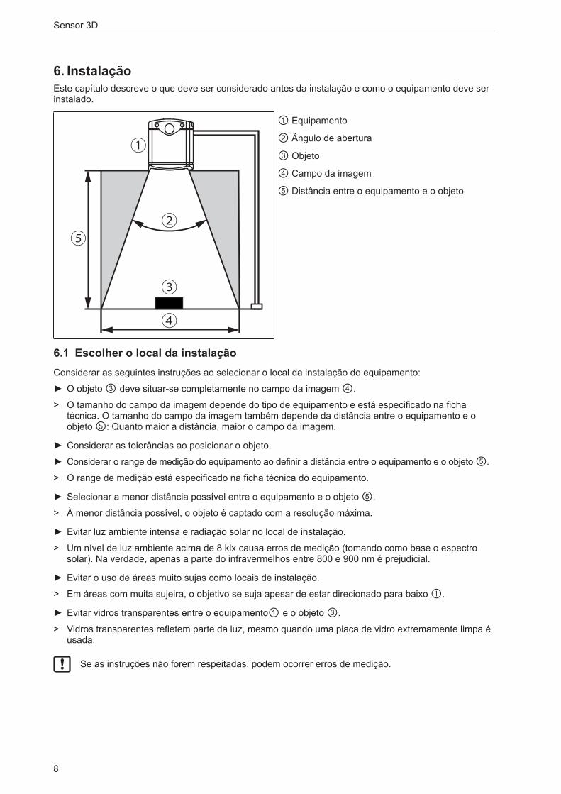
6. InstalaçãoEste capítulo descreve o que deve ser considerado antes da instalação e como o equipamento deve ser instalado.
②
①
③
④
⑤
① Equipamento
② Ângulo de abertura
③ Objeto
④ Campo da imagem
⑤ Distância entre o equipamento e o objeto
6.1 Escolher o local da instalaçãoConsiderar as seguintes instruções ao selecionar o local da instalação do equipamento:
► O objeto ③ deve situar-se completamente no campo da imagem ④.
> O tamanho do campo da imagem depende do tipo de equipamento e está especificado na ficha técnica. O tamanho do campo da imagem também depende da distância entre o equipamento e o objeto ⑤: Quanto maior a distância, maior o campo da imagem.
► Considerar as tolerâncias ao posicionar o objeto.
► Considerar o range de medição do equipamento ao definir a distância entre o equipamento e o objeto ⑤.
> O range de medição está especificado na ficha técnica do equipamento.
► Selecionar a menor distância possível entre o equipamento e o objeto ⑤.
> À menor distância possível, o objeto é captado com a resolução máxima.
► Evitar luz ambiente intensa e radiação solar no local de instalação.
> Um nível de luz ambiente acima de 8 klx causa erros de medição (tomando como base o espectro solar). Na verdade, apenas a parte do infravermelhos entre 800 e 900 nm é prejudicial.
► Evitar o uso de áreas muito sujas como locais de instalação.
> Em áreas com muita sujeira, o objetivo se suja apesar de estar direcionado para baixo ①.
► Evitar vidros transparentes entre o equipamento① e o objeto ③.
> Vidros transparentes refletem parte da luz, mesmo quando uma placa de vidro extremamente limpa é usada.
Se as instruções não forem respeitadas, podem ocorrer erros de medição.

9
Sensor 3D
PT
6.2 Preparar o equipamento para ser colocado em funcionamentoA temperatura superficial do equipamento depende do modo de operação, da escolha dos parâmetros e da ligação térmica do equipamento com o meio ambiente.
Certifique-se de que o equipamento atenda os seguintes requisitos:
A temperatura superficial de superfícies facilmente tangíveis pode ser no máx. 25°C mais alta que a temperatura ambiente (conforme a norma IEC61010-2-201).
Os seguintes diagramas contêm limites de advertência típicos, que podem ser usados como orientação pelo instalador.
Os diagramas são válidos para os seguintes modos de exposição luminosa:
● um tempo de exposição luminosa
● dois tempos de exposição luminosa
● três tempos de exposição luminosa
No caso de dois ou três tempos de exposição luminosa, os limites de advertência típicos devem ser determinados por meio da soma dos tempos de exposição luminosa. Os tempos de exposição luminosa são exibidos no software ifm Vision Assistant.
Siga uma das instruções abaixo, se os limites de advertência forem ultrapassados:
► Reduzir da temperatura de superfície (→ 6.2.3).
► Instalar a proteção contra contatos sem restringir a convecção (movimentação do ar).
> A temperatura a superfície não deve aumentar com a instalação da proteção contra contatos.
O parâmetro "Distância máxima visível" é configurado no ifm Vision Assistant. Os limites de advertência dos parâmetros são exibidos com linhas pontilhadas e contínuas nos diagramas.
Se o equipamento estiver em uma das áreas pontilhadas, a temperatura da superfície deve ser reduzida (→ 6.2.3). Se o limite de advertência for excedido apesar da instalação com dissipação de calor, a proteção contra contatos pode ser instalada adicionalmente.
Se durante a instalação normal os limites de advertência típicos não forem alcançados, nenhuma ação é necessária.
6.2.1 Limites de advertência típicos para O3D300 / O3D302
0
5
10
15
0 2 4 6 8 10
x
y
20
25
Parâmetro "Distância máxima visível"
Instalação em peças metálicas condutoras de calor com placa condutora de calor (→ 6.2.3)
Limite de advertência Parâmetro
< 5 m
< 30 m
> 30 m
Instalação normal
Limite de advertência Parâmetro
< 5 m
< 30 m
> 30 m
x = tempo de exposição [ms] y = taxa de fotogramas [fps]
Sensor 3D
10
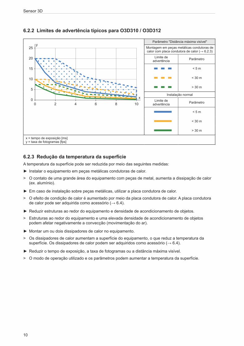
6.2.2 Limites de advertência típicos para O3D310 / O3D312
0
5
10
15
0 2 4 6 8 10
x
y
20
25
Parâmetro "Distância máxima visível"
Montagem em peças metálicas condutoras de calor com placa condutora de calor (→ 6.2.3)
Limite de advertência Parâmetro
< 5 m
< 30 m
> 30 m
Instalação normal
Limite de advertência Parâmetro
< 5 m
< 30 m
> 30 m
x = tempo de exposição [ms] y = taxa de fotogramas [fps]
6.2.3 Redução da temperatura da superfícieA temperatura da superfície pode ser reduzida por meio das seguintes medidas:
► Instalar o equipamento em peças metálicas condutoras de calor.
> O contato de uma grande área do equipamento com peças de metal, aumenta a dissipação de calor (ex. alumínio).
► Em caso de instalação sobre peças metálicas, utilizar a placa condutora de calor.
> O efeito de condição de calor é aumentado por meio da placa condutora de calor. A placa condutora de calor pode ser adquirida como acessório (→ 6.4).
► Reduzir estruturas ao redor do equipamento e densidade de acondicionamento de objetos.
> Estruturas ao redor do equipamento e uma elevada densidade de acondicionamento de objetos podem afetar negativamente a convecção (movimentação do ar).
► Montar um ou dois dissipadores de calor no equipamento.
> Os dissipadores de calor aumentam a superfície do equipamento, o que reduz a temperatura da superfície. Os dissipadores de calor podem ser adquiridos como acessório (→ 6.4).
► Reduzir o tempo de exposição, a taxa de fotogramas ou a distância máxima visível.
> O modo de operação utilizado e os parâmetros podem aumentar a temperatura da superfície.
11
Sensor 3D
PT
6.3 Instalar o equipamentoObserve as seguintes instruções durante a instalação do equipamento:
► Instalar o equipamento com 2 parafusos M5 ou com o kit de instalação.
> As dimensões de perfuração para os parafusos M5 estão especificadas na ficha técnica.
> O kit de instalação pode ser adquirido como acessório (→ 6.4).
► Utilizar dispositivos de alívio de tração para todas as linhas conectadas ao equipamento.
Observe as seguintes instruções durante a instalação de um O3D300 e O3D310:
► Instalar o equipamento de tal forma que o focalizador possa ser alcançado com uma chave de fenda.
> A posição do focalizador está especificada no diagrama dimensional (→ 12).
Em caso de uso permanente do equipamento em áreas úmidas, a porca da bucha do cabo de conexão Ethernet industrial M12 (ex. E11898) pode corroer-se. Para uso permanente em áreas úmidas, utilize um cabo de conexão com porca de bucha V4A.
6.4 Acessórios de instalaçãoDependendo do local de instalação e da instalação em si, podem ser utilizados os seguintes acessórios de instalação:
Número do artigo Nome
E3D301 Kit de instalação Smart CameraE3D302 Dissipador de calor Smart CameraE3D303 Placa condutora de calor Smart CameraE3D304 2x dissipadores de calor Smart Camera
Informações sobre os acessórios em: www.ifm.com
Sensor 3D
12
7. Conexão elétricaObserve as seguintes instruções antes da instalação elétrica.
ATENÇÃO O equipamento deve ser instalado somente por um técnico eletricista qualificado. Observar os dados elétricos especificados na ficha técnica.
Equipamento da classe de proteção III (SK III)
A alimentação elétrica só pode ser realizada através de circuitos PELV.
A alimentação elétrica deve corresponder ao UL61010-1, cap. 9.4 - Limited Energy:
O dispositivo de proteção de sobrecorrente deve desligar uma corrente de 6,6 A em 120 s. Ao dimensionar o dispositivo de proteção de sobrecorrente, levar em conta os dados técnicos do equipamento e o cabeamento.
O isolamento do circuito externo deve corresponder ao UL61010-2-201, fig. 102.
No caso de cabos > 30 m de comprimento, utilizar uma proteção adicional contra sobrecargas, conforme a norma IEC6100-4-5.
Desligar a alimentação de tensão antes de proceder com a conexão elétrica.
Para o escopo cULus: Resistência térmica mínima do cabo para conectar a bornes de campo: 70 °C.
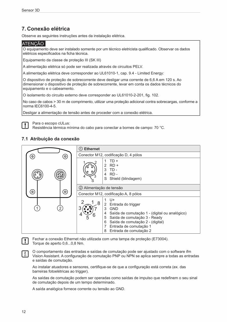
7.1 Atribuição da conexão
① EthernetConector M12, codificação D, 4 pólos
����������������
�
� �
��
��� ��
��������
�
� �
�
�
1 TD + 2 RD + 3 TD - 4 RD - S Shield (blindagem)
② Alimentação de tensãoConector M12, codificação A, 8 pólos
6
2 1
45
738
1 U+ 2 Entrada do trigger 3 GND 4 Saída de comutação 1 - (digital ou analógico) 5 Saída de comutação 3 - Ready 6 Saída de comutação 2 - (digital) 7 Entrada de comutação 1 8 Entrada de comutação 2
Fechar a conexão Ethernet não utilizada com uma tampa de proteção (E73004). Torque de aperto 0,6...0,8 Nm.
O comportamento das entradas e saídas de comutação pode ser ajustado com o software ifm Vision Assistant. A configuração de comutação PNP ou NPN se aplica sempre a todas as entradas e saídas de comutação.
Ao instalar atuadores e sensores, certifique-se de que a configuração está correta (ex. das barreiras fotoelétricas ao trigger).
As saídas de comutação podem ser operadas como saídas de impulso que redefinem o seu sinal de comutação depois de um tempo determinado.
A saída analógica fornece corrente ou tensão ao GND.
13
Sensor 3D
PT
7.1.1 Pino 1 / 3 (24 V / GND)O range de tensão permitido está especificado na ficha técnica do equipamento.
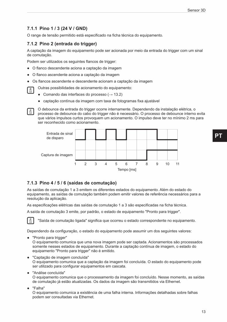
7.1.2 Pino 2 (entrada do trigger)A captação da imagem do equipamento pode ser acionada por meio da entrada do trigger com um sinal de comutação.
Podem ser utilizados os seguintes flancos de trigger:
● O flanco descendente aciona a captação da imagem
● O flanco ascendente aciona a captação da imagem
● Os flancos ascendente e descendente acionam a captação da imagem
Outras possibilidades de acionamento do equipamento:
● Comando das interfaces do processo (→ 13.2)
● captação contínua da imagem com taxa de fotogramas fixa ajustável
O debounce da entrada do trigger ocorre internamente. Dependendo da instalação elétrica, o processo de debounce do cabo do trigger não é necessário. O processo de debounce interno evita que vários impulsos curtos provoquem um acionamento. O impulso deve ter no mínimo 2 ms para ser reconhecido como acionamento.
7.1.3 Pino 4 / 5 / 6 (saídas de comutação)As saídas de comutação 1 a 3 emitem os diferentes estados do equipamento. Além do estado do equipamento, as saídas de comutação também podem emitir valores de referência necessários para a resolução da aplicação.
As especificações elétricas das saídas de comutação 1 a 3 são especificadas na ficha técnica.
A saída de comutação 3 emite, por padrão, o estado de equipamento "Pronto para trigger".
"Saída de comutação ligada" significa que ocorreu o estado correspondente no equipamento.
Dependendo da configuração, o estado do equipamento pode assumir um dos seguintes valores:
● "Pronto para trigger" O equipamento comunica que uma nova imagem pode ser captada. Acionamentos são processados somente nesses estados de equipamento. Durante a captação contínua de imagem, o estado do equipamento "Pronto para trigger" não é emitido.
● "Captação de imagem concluída" O equipamento comunica que a captação da imagem foi concluída. O estado do equipamento pode ser utilizado para configurar equipamentos em cascata.
● "Análise concluída" O equipamento comunica que o processamento da imagem foi concluído. Nesse momento, as saídas de comutação já estão atualizadas. Os dados da imagem são transmitidos via Ethernet.
● "Falha" O equipamento comunica a existência de uma falha interna. Informações detalhadas sobre falhas podem ser consultadas via Ethernet.
Captura de imagem
Entrada de sinalde disparo
Tempo [ms]1 2 3 4 5 6 7 8 9 10 11

Sensor 3D
14
7.1.4 Pino 4 (saída analógica)A saída de comutação 1 / saída analógica pode ser utilizada como saída de comutação ou corrente de saída analógica (4-20 mA) /saída de tensão analógica (0-10 V).
A saída de corrente analógica oferece uma maior segurança de transmissão em relação à saída de tensão analógica. A saída de corrente analógica independe do comprimento do cabo e oferece uma qualidade de sinal superior na direção do controle industrial.
No controle industrial, o fluxo analógico é convertido em tensão analógica através de uma resistência de carga contra GND. A resistência de carga é selecionada de acordo com os dados da ficha técnica. Resistências de carga de alta impedância são preferíveis em relação às de baixa impedância devido à baixa produção de calor no equipamento.
3 1 4 5 6 7 8
1 2
34
6
2 1
45
738
PLC
DC 24 V+ -
IN IN IN OUT OUT
①
②③
Analog
① Notebook (parametrizar)
② Controle industrial (analisar / trigger)
③ Resistência de carga
Com o software ifm Vision Assistant, pode-se atribuir um valor do processo a cada valor inicial (4 mA / 0 V) e valor final (20 mA / 10 V) da saída analógica.
7.1.5 Pino 7 / 8 (entradas de comutação)As entradas de comutação fornecem as seguintes funções:
● selecionar aplicação ativa (→ 7.3)
As diversas parametrizações das funções estão especificadas no manual do programa.
As especificações elétricas da entrada de comutação 1 e da entrada de comutação 2 são especificadas na ficha técnica do equipamento.

15
Sensor 3D
PT
7.2 Exemplos de cabeamentoA seguir são ilustrados exemplos de cabeamento do equipamento.
7.2.1 Acionar captação de imagem com interruptor de proximidadeO equipamento pode ser acionado externamente:
● pela Ethernet
● por meio de um interruptor de proximidade, conectado à entrada do trigger
A figura a seguir mostra a calibragem do equipamento com um interruptor de proximidade.
3 1 2 4 5 6 7 8
1 2
34
6
2 1
45
738
PLC
DC 24 V+ -
IN IN IN OUT OUT
①
② ③
① Notebook (parametrizar)
② Interruptor de proximidade
③ Controle industrial (analisar / trigger)

Sensor 3D
16
7.2.2 Utilizar vários equipamentos lado a ladoEquipamentos instalados lado a lado podem causar falhas de medição devido à exposição simultânea.
① ②
③
① Equipamento
② Equipamento
③ Objeto
Os erros de medição podem ser evitados de duas formas:
● Configurar equipamentos em cascata pelo hardware de trigger Ao configurar em cascata, um controle aciona a captação da imagem do equipamento ① (ver fig. abaixo). Após a conclusão da captação da imagem, o equipamento ① aciona independentemente o equipamento ②. Nesse processo, o pino 4 do equipamento ① emite o estado do equipamento "Captação da imagem finalizada". O equipamento ② comunica a conclusão da sequência do controle industrial ③.
3 1 2 4 5
DC 24 V+ -
3 1 2 5
③
6
2 1
45
738
PLC
IN IN IN OUT OUT
6 7
① ② ① Equipamento
② Equipamento
③ Controle industrial (analisar / trigger)
● Utilizar diferentes canais de frequência Com o software ifm Vision Assistant, pode-se atribuir um canal de frequência próprio a cada equipamento. Os diferentes canais de frequência reduzem a incidência de erros de medição.
O software ifm Vision Assistant está disponível gratuitamente na internet: www.ifm.com

17
Sensor 3D
PT
7.3 Seleção de aplicação estáticaAté 32 tarefas de inspeção diferentes podem ser salvas no equipamento. Com a configuração correspondente, podem ser selecionadas as primeiras quatro aplicações, através de ambas entradas de comutação.
Entrada 2 Entrada 1 Aplicação nº0 0 10 1 21 0 31 1 4
0
1
0
1
0
1
t
1 2 3- -
RR
Exemplo: comutação aplicação 1 → aplicação 2 → aplicação 3
① Entrada de comutação 1 = 0 → 1 → 0
② Entrada de comutação 2 = 0 → 0 → 1
③ Saída READY
④ Entrada do triggerA: Trigger permitidoB: Trigger bloqueado
⑤ Número de ID da aplicação ativa
Ao selecionar as aplicações, deve-se ter em conta o tempo de monitoramento tR e o período de bloqueio do trigger tP.
Tempo de monitoramento tR: A seleção da aplicação começa somente quando, após uma mudança de flanco, o estado em ambas as entradas de comutação permanecer estável por 20 ms.
Período de bloqueio do trigger tP: Durante a seleção da aplicação, a entrada do trigger é bloqueada. O tempo de bloqueio depende:
● do número de aplicações presentes no equipamento
● do número de modelos presentes na aplicação a ser ativada
Na figura acima, está configurada a lógica de saída PNP (configuração padrão). As lógicas de saída PNP e NPN comportam-se de forma inversa uma à outra:
● Lógica de saída PNP: a tensão está aplicada no caso de sinal alto (high) (1). ● Lógica de saída NPN: a tensão está aplicada no caso de sinal baixo (low) (0).
Maiores informações sobre a configuração da seleção de aplicação podem ser encontradas no manual de software do equipamento. www.ifm.com

Sensor 3D
18
7.4 Seleção de aplicação controlada por impulsoAlternativamente à seleção estática, a escolha da aplicação pode ser controlada por impulso.
1 2 3 4 5
① Gate-Signal, entrada de comutação 1 = 0 → 1 → 0 (tG = sinal ativo)
② Sinal de impulso, entrada de comutação 2 ou entrada do trigger = 0 → 5 impulsos → 0
③ Saída READY
Enquanto na entrada de comutação 1 há um sinal ativo (Gate-Signal), o equipamento conta impulsos entrantes e ativa a aplicação correspondente.
Número de impulsos = Número de ID da aplicação.
Como entrada de impulso, pode-se utilizar tanto a entrada de comutação 2 ou a entrada de trigger do equipamento.
Na figura acima, está configurada a lógica de saída PNP (configuração padrão). As lógicas de saída PNP e NPN comportam-se de forma inversa uma à outra:
● Lógica de saída PNP: a tensão está aplicada no caso de sinal alto (high) (1).
● Lógica de saída NPN: a tensão está aplicada no caso de sinal baixo (low) (0).
Maiores informações sobre a configuração da seleção de aplicação podem ser encontradas no manual de software do equipamento. www.ifm.com

19
Sensor 3D
PT
8. Elementos de exibiçãoO equipamento sinaliza o estado atual de funcionamento por meio dos LEDs 1 a 4 do elemento de exibição.
LED 4 LED 3LED 1 LED 2
LED 4 (Ethernet)
LED 1 (Power)
LED 2 (Out 1)
LED 3 (Out 2)
Descrição
aceso O equipamento está pronto para operar, tensão de alimentação é aplicada
pisca com 0,5 Hz
O equipamento não está parametrizado ou a parametrização não foi carregada no equipamento
On
On
Off
Off
pisca 2x com 0,5 Hz
O equipamento está no modo de parametrização
On
On
Off
Offaceso A saída de comutação 1 está ligadapisca com 8 Hz
A saída de comutação 1 tem um curto-circuito
aceso A saída de comutação 2 está ligadapisca com 8 Hz
A saída de comutação 2 tem um curto-circuito
aceso A Ethernet está conectadapisca A Ethernet transmite dadosdesligado A Ethernet não está conectada
pisca com 8 Hz
pisca com 8 Hz
O equipamento sinaliza uma falha interna
pisca com 2 Hz
pisca com 2 Hz
O equipamento sinaliza uma falha remediável. A mensagem de erro pode ser lida via Ethernet
Luz em movimento ⇒ O equipamento inicializa
Luz em movimento ⇐ O equipamento está executando a atualização do firmware

Sensor 3D
20
9. Colocação em funcionamentoO equipamento entra em funcionamento quando a tensão de alimentação é ligada. Após 15 segundos, o equipamento encontra-se em modo de processamento, no qual aplicações salvas são executadas. Os elementos de exibição sinalizam o estado de funcionamento atual (→ 8).
Até 32 aplicações podem ser salvas no equipamento. Uma aplicação pode ser ativada de diferentes maneiras:
● software ifm Vision Assistant
● Comando das interfaces do processo
● Entrada de comutação 1 e 2
● Entrada de comutação 1 e entrada do trigger
9.1 Parametrizar o equipamentoO equipamento é parametrizado com o software ifm Vision Assistant (→ ver Manual do programa).
A utilização do software ifm Vision Assistant e informações detalhadas sobre o princípio de medição do equipamento estão descritas no manual do software.
O software ifm Vision Assistant está disponível gratuitamente na internet: www.ifm.com
O manual do software está disponível na internet: www.ifm.com
9.2 Detectar objetoA seguir são descritas quais condições conduzem a uma elevada taxa de detecção de objetos.
③
②
④
②
①① Equipamento
② Área de influência
③ Campo de visão
④ Objeto
Um objeto ④ é detectado de forma ideal, quando forem cumpridos os seguintes requisitos:
● O objeto está posicionado no campo de visão ③ ● O objeto é o objeto visível mais próximo do equipamento ① ● Área de influência ② está livre de objetos (estruturas, etc.)
● O visor frontal do equipamento está livre de sujeiras.
Se as condições não forem cumpridas, podem ocorrer erros de medição.

21
Sensor 3D
PT
9.3 Enviar valores do processo
9.3.1 Enviar valores de processo do monitoramento de integridade via Ethernet/IPO equipamento pode enviar os valores de processo a um CLP através do barramento de campo Ethernet/IP. Os valores de processo são exibidos no ifm Vision Assistant como string de saída da seguinte forma:
Somente um barramento de campo pode estar ativo por vez. O Barramento de campo pode ser ajustado (→ Manual do software).
No string de saída os valores de processo são separados por ponto e vírgula. O string de saída é transferido para um CLP na ordem apresentada.
Observe as seguintes instruções ao transferir o string de saída para um CLP:
● Os bytes 0 a 7 fazem parte do string de saída. Eles não são exibidos no ifm Vision Assistant (ver captura de tela acima).
● Os pontos e vírgulas ";" contidos no string de saída não são transferidos.
● Valores float são transformados em 16 bits inteiros antes da transferência.
● Todos os valores numéricos são transformados em 16 bits inteiros antes da transferência.
O string de saída apresenta a seguinte composição:
star;0;00;0;+0.000;01;7;-0.068;02;6;+0.013;03;0;+0.001;stop
Nº do byte Dados Codificação Valor do processo Unidade Descrição Comentário
0 2#0000_0000 Binário1.5 Palavra de comando
duplicada ● O bit 1.5 exibe um comando de trigger bem-sucedido1 2#0010_0000 Binário
2 2#0000_0000 Decimal Identificação de mensagem sincrônica/ assincrônica
3 2#0000_0000 Decimal
4 30 Decimal
30 Contador de mensagens
● O equipamento recebeu 30 mensagens
● Incrementa em 1, em cada ação (trigger, men-sagem enviada, etc.)
5 0 Decimal
6 0 DecimalReservado
7 0 Decimal
8 s ASCII
star String de início9 t ASCII
10 a ASCII
11 r ASCII
12 0 Decimal0
Estado de todos os ROIs (0 = ruim, 1 = bom)
Exibe o estado do monitoramento de integridade13 0 Decimal

Sensor 3D
22
Nº do byte Dados Codificação Valor do processo Unidade Descrição Comentário
14 0 Decimal
0 ID do ROI
Quando a função de ajustamento de posição estiver ativada, os bytes 14 e 15 são ocupados por esta função.0 = a posição não é ajustada1 = a posição é ajustadaTodos os dados seguintes se deslocam em 2 bytes; isto é, o 1º ID de ROI começa com o byte 16 e 17.
15 0 Decimal
16 0 Decimal0 Estado do ROI
Estado do ROI:0 = Bom1 = Nível de referência não programado2 = Falha ao programar3 = Nível de referência inválido4 = nenhum pixel válido5 = Nível de referência não contém nenhum pixel válido6 = Enchimento excessivo7 = Enchimento insuficiente
17 0 Decimal
18 0 Decimal0 mm Valor do ROI
19 0 Decimal
20 1 Decimal1 ID do ROI
21 0 Decimal
22 7 Decimal7 Estado do ROI
23 0 Decimal
24 -67 Decimal-67 mm Valor do ROI
25 -1 Decimal
26 2 Decimal2 ID do ROI
27 0 Decimal
28 6 Decimal6 Estado do ROI
29 0 Decimal
30 14 Decimal14 mm Valor do ROI
31 0 Decimal
32 3 Decimal3 ID do ROI
33 0 Decimal
34 0 Decimal0 Estado do ROI
35 0 Decimal
36 0 Decimal0 mm Valor do ROI
37 0 Decimal
38 s ASCII
stop String de parada39 t ASCII
40 o ASCII
41 p ASCII
A execução errônea de um comando leva à seguinte condição:
● Bit de falha (error bit) = 1
● A palavra de comando duplicada é exibida
● Bit de mensagens assincrônico = 0
● Identificação de mensagens assincrônica = 0
● Contador de mensagens incrementa em 1

23
Sensor 3D
PT
9.3.2 Enviar valores de processo do monitoramento de integridade via PROFINETO equipamento pode enviar os valores de processo a um CLP através do barramento de campo PROFINET. Os valores de processo são exibidos no ifm Vision Assistant como string de saída da seguinte forma:
Somente um barramento de campo pode estar ativo por vez. O Barramento de campo pode ser ajustado (→ Manual do software).
No string de saída, os valores de processo são separados por ponto e vírgula. O string de saída é transferido para um CLP na ordem apresentada.
Observe as seguintes instruções ao transferir o string de saída para um CLP:
● Os bytes 0 a 7 fazem parte do string de saída. Eles não são exibidos no ifm Vision Assistant (ver captura de tela acima).
● Os pontos e vírgulas ";" contidos no string de saída não são transferidos.
● Valores float são transformados em 16 bits inteiros antes da transferência.
● Todos os valores numéricos são transformados em 16 bits inteiros antes da transferência.
O string de saída apresenta a seguinte composição:
star;0;00;0;+0.000;01;7;-0.068;02;6;+0.013;03;0;+0.001;stop
Nº do byte Dados Codificação Valor do processo Unidade Descrição Comentário
0 2#0010_0000 Binário0.5 Palavra de comando
duplicada ● O bit 0.5 exibe um comando de trigger bem-sucedido1 2#0000_0000 Binário
2 2#0000_0000 Decimal Identificação de mensagem sincrônica/ assincrônica
3 2#0000_0000 Decimal
4 0 Decimal
30 Contador de mensagens
● O equipamento recebeu 30 mensagens
● Incrementa em 1, em cada ação (trigger, men-sagem enviada, etc.)
5 30 Decimal
6 0 DecimalReservado
7 0 Decimal
8 s ASCII
star String de início9 t ASCII
10 a ASCII
11 r ASCII
12 0 Decimal0
Estado de todos os ROIs (0 = ruim, 1 = bom)
Exibe o estado do monitoramento de integridade13 0 Decimal

Sensor 3D
24
Nº do byte Dados Codificação Valor do processo Unidade Descrição Comentário
14 0 Decimal
0 ID do ROI
Quando a função de ajustamento de posição estiver ativada, os bytes 14 e 15 são ocupados por esta função.0 = a posição não é ajustada1 = a posição é ajustadaTodos os dados seguintes se deslocam em 2 bytes; isto é, o 1º ID de ROI começa com o byte 16 e 17.
15 0 Decimal
16 0 Decimal0 Estado do ROI
Estado do ROI:0 = Bom1 = Nível de referência não programado2 = Falha ao programar3 = Nível de referência inválido4 = Nenhum pixel válido5 = Nível de referência não contém nenhum pixel válido6 = Enchimento excessivo7 = Enchimento insuficiente
17 0 Decimal
18 0 Decimal0 mm Valor do ROI
19 0 Decimal
20 0 Decimal1 ID do ROI
21 1 Decimal
22 0 Decimal7 Estado do ROI
23 7 Decimal
24 -1 Decimal-67 mm Valor do ROI
25 -67 Decimal
26 0 Decimal2 ID do ROI
27 2 Decimal
28 0 Decimal6 Estado do ROI
29 6 Decimal
30 0 Decimal14 mm Valor do ROI
31 14 Decimal
32 0 Decimal3 ID do ROI
33 3 Decimal
34 0 Decimal0 Estado do ROI
35 0 Decimal
36 0 Decimal0 mm Valor do ROI
37 0 Decimal
38 s ASCII
stop String de parada39 t ASCII
40 o ASCII
41 p ASCII
A execução errônea de um comando leva à seguinte condição:
● Bit de falha (error bit) = 1
● A palavra de comando duplicada é exibida
● Bit de mensagens assincrônico = 0
● Identificação de mensagens assincrônica = 0
● Contador de mensagens incrementa em 1

25
Sensor 3D
PT
9.3.3 Enviar valores de processo do monitoramento de integridade via TCP/IPO equipamento pode enviar os valores de processo a um CLP via protocolo TCP/IP. Os valores de processo são exibidos no ifm Vision Assistant como string de saída da seguinte forma:
No string de saída os valores de processo são separados por ponto e vírgula. O string de saída é transferido para um CLP na ordem apresentada.
Observe as seguintes instruções ao transferir o string de saída para um CLP:
● Os pontos e vírgulas ";" contidos no string de saída não são transferidos.
● Todos os valores numéricos são transformados em 16 bits inteiros antes da transferência.
O string de saída apresenta a seguinte composição (tipo de dado: ASCII)
star;0;00;0;+0.000;01;7;-0.068;02;6;+0.013;03;0;+0.001;stop
Valor do processo Unidade Descrição
star String de início
0 Estado de todos os ROIs (0 = ruim, 1 = bom)
00 ID do ROI
Estado do ROI:0 = Bom1 = Nível de referência não programado2 = Falha ao programar3 = Nível de referência inválido4 = Nenhum pixel válido5 = Nível de referência não contém nenhum pixel válido6 = Enchimento excessivo7 = Enchimento insuficiente
0 Estado do ROI
+0.000 m Valor do ROI
01 ID do ROI
7 Estado do ROI
-0.068 m Valor do ROI
02 ID do ROI
6 Estado do ROI
+0.013 m Valor do ROI
03 ID do ROI
0 Estado do ROI
+0.001 m Valor do ROI
stop String de parada
Sensor 3D
26
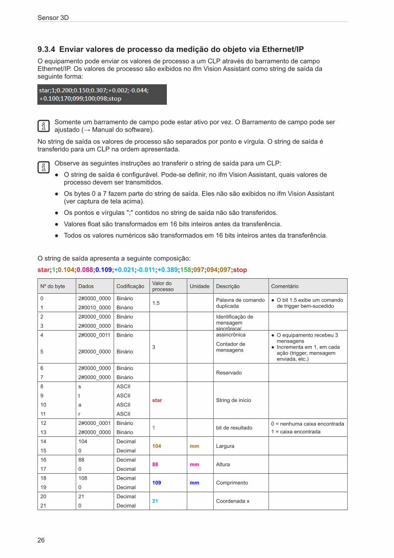
9.3.4 Enviar valores de processo da medição do objeto via Ethernet/IPO equipamento pode enviar os valores de processo a um CLP através do barramento de campo Ethernet/IP. Os valores de processo são exibidos no ifm Vision Assistant como string de saída da seguinte forma:
Somente um barramento de campo pode estar ativo por vez. O Barramento de campo pode ser ajustado (→ Manual do software).
No string de saída os valores de processo são separados por ponto e vírgula. O string de saída é transferido para um CLP na ordem apresentada.
Observe as seguintes instruções ao transferir o string de saída para um CLP:
● O string de saída é configurável. Pode-se definir, no ifm Vision Assistant, quais valores de processo devem ser transmitidos.
● Os bytes 0 a 7 fazem parte do string de saída. Eles não são exibidos no ifm Vision Assistant (ver captura de tela acima).
● Os pontos e vírgulas ";" contidos no string de saída não são transferidos.
● Valores float são transformados em 16 bits inteiros antes da transferência.
● Todos os valores numéricos são transformados em 16 bits inteiros antes da transferência.
O string de saída apresenta a seguinte composição:
star;1;0.104;0.088;0.109;+0.021;-0.011;+0.389;158;097;094;097;stop
Nº do byte Dados Codificação Valor do processo Unidade Descrição Comentário
0 2#0000_0000 Binário1.5 Palavra de comando
duplicada ● O bit 1.5 exibe um comando de trigger bem-sucedido1 2#0010_0000 Binário
2 2#0000_0000 Binário Identificação de mensagem sincrônica/ assincrônica
3 2#0000_0000 Binário
4 2#0000_0011 Binário
3 Contador de mensagens
● O equipamento recebeu 3 mensagens
● Incrementa em 1, em cada ação (trigger, mensagem enviada, etc.)
5 2#0000_0000 Binário
6 2#0000_0000 BinárioReservado
7 2#0000_0000 Binário
8 s ASCII
star String de início9 t ASCII
10 a ASCII
11 r ASCII
12 2#0000_0001 Binário1 bit de resultado
0 = nenhuma caixa encontrada1 = caixa encontrada13 2#0000_0000 Binário
14 104 Decimal104 mm Largura
15 0 Decimal
16 88 Decimal88 mm Altura
17 0 Decimal
18 108 Decimal109 mm Comprimento
19 0 Decimal
20 21 Decimal21 Coordenada x
21 0 Decimal
27
Sensor 3D
PT
Nº do byte Dados Codificação Valor do processo Unidade Descrição Comentário
22 -11 Decimal-11 Coordenada y
23 -1 Decimal
24 -124 Decimal389 Coordenada z
25 1 Decimal
26 -98 Decimal158 Grau de rotação
27 0 Decimal
28 97 Decimal97 Qualidade largura
29 0 Decimal
30 93 Decimal94 Qualidade altura
31 0 Decimal
32 97 Decimal97 Qualidade
comprimento33 0 Decimal
34 s ASCII
stop String de parada35 t ASCII
36 o ASCII
37 p ASCII
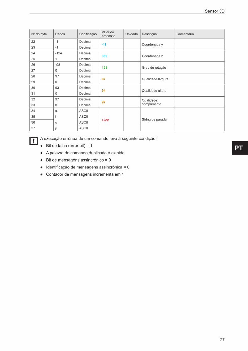
A execução errônea de um comando leva à seguinte condição:
● Bit de falha (error bit) = 1
● A palavra de comando duplicada é exibida
● Bit de mensagens assincrônico = 0
● Identificação de mensagens assincrônica = 0
● Contador de mensagens incrementa em 1

Sensor 3D
28
9.3.5 Enviar valores de processo da medição do objeto via PROFINETO equipamento pode enviar os valores de processo a um CLP através do barramento de campo PROFINET. Os valores de processo são exibidos no ifm Vision Assistant como string de saída da seguinte forma:
Somente um barramento de campo pode estar ativo por vez. O Barramento de campo pode ser ajustado (→ Manual do software).
No string de saída, os valores de processo são separados por ponto e vírgula. O string de saída é transferido para um CLP na ordem apresentada.
Observe as seguintes instruções ao transferir o string de saída para um CLP:
● O string de saída é configurável. Pode-se definir no ifm Vision Assistant, quais valores de processo devem ser transmitidos.
● Os bytes 0 a 7 fazem parte do string de saída. Eles não são exibidos no ifm Vision Assistant (ver captura de tela acima).
● Os pontos e vírgulas ";" contidos no string de saída não são transferidos.
● Valores float são transformados em 16 bits inteiros antes da transferência.
● Todos os valores numéricos são transformados em 16 bits inteiros antes da transferência.
O string de saída apresenta a seguinte composição:
star;1;0.104;0.088;0.109;+0.021;-0.011;+0.389;158;097;094;097;stop
Nº do byte Dados Codificação Valor do processo Unidade Descrição Comentário
0 2#0010_0000 Binário0.5 Palavra de comando
duplicada ● O bit 0.5 exibe um comando de trigger bem-sucedido1 2#0000_0000 Binário
2 2#0000_0000 Binário Identificação de mensagem sincrônica/ assincrônica
3 2#0000_0000 Binário
4 2#0000_0000 Binário
3 Contador de mensagens
● O equipamento recebeu 3 mensagens
● Incrementa em 1, em cada ação (trigger, mensagem enviada, etc.)
5 2#0000_0011 Binário
6 2#0000_0000 BinárioReservado
7 2#0000_0000 Binário
8 s ASCII
star String de início9 t ASCII
10 a ASCII
11 r ASCII
12 2#0000_0000 Binário1 bit de resultado
0 = nenhuma caixa encontrada1 = caixa encontrada13 2#0000_0001 Binário
14 0 Decimal104 mm Largura
15 104 Decimal
16 0 Decimal88 mm Altura
17 88 Decimal
18 0 Decimal109 mm Comprimento
19 109 Decimal
20 0 Decimal21 Coordenada x
21 21 Decimal
29
Sensor 3D
PT
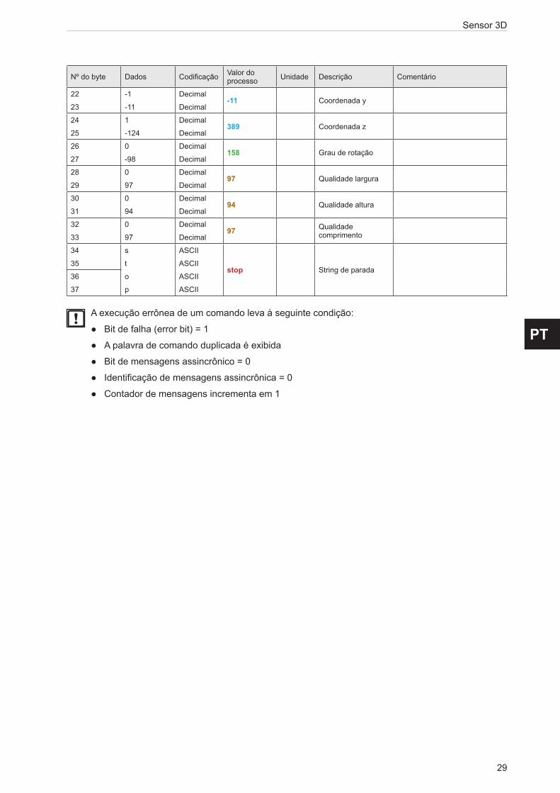
Nº do byte Dados Codificação Valor do processo Unidade Descrição Comentário
22 -1 Decimal-11 Coordenada y
23 -11 Decimal
24 1 Decimal389 Coordenada z
25 -124 Decimal
26 0 Decimal158 Grau de rotação
27 -98 Decimal
28 0 Decimal97 Qualidade largura
29 97 Decimal
30 0 Decimal94 Qualidade altura
31 94 Decimal
32 0 Decimal97 Qualidade
comprimento33 97 Decimal
34 s ASCII
stop String de parada35 t ASCII
36 o ASCII
37 p ASCII
A execução errônea de um comando leva à seguinte condição:
● Bit de falha (error bit) = 1
● A palavra de comando duplicada é exibida
● Bit de mensagens assincrônico = 0
● Identificação de mensagens assincrônica = 0
● Contador de mensagens incrementa em 1
Sensor 3D
30
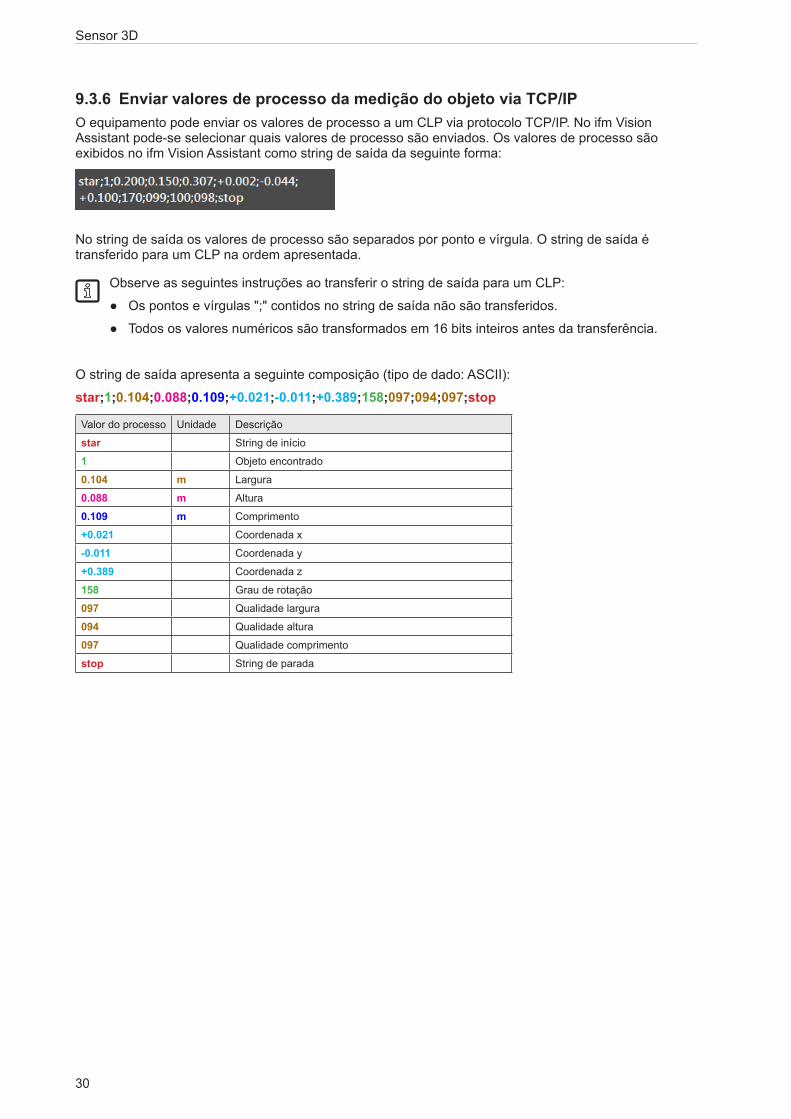
9.3.6 Enviar valores de processo da medição do objeto via TCP/IPO equipamento pode enviar os valores de processo a um CLP via protocolo TCP/IP. No ifm Vision Assistant pode-se selecionar quais valores de processo são enviados. Os valores de processo são exibidos no ifm Vision Assistant como string de saída da seguinte forma:
No string de saída os valores de processo são separados por ponto e vírgula. O string de saída é transferido para um CLP na ordem apresentada.
Observe as seguintes instruções ao transferir o string de saída para um CLP:
● Os pontos e vírgulas ";" contidos no string de saída não são transferidos.
● Todos os valores numéricos são transformados em 16 bits inteiros antes da transferência.
O string de saída apresenta a seguinte composição (tipo de dado: ASCII):
star;1;0.104;0.088;0.109;+0.021;-0.011;+0.389;158;097;094;097;stop
Valor do processo Unidade Descrição
star String de início
1 Objeto encontrado
0.104 m Largura
0.088 m Altura
0.109 m Comprimento
+0.021 Coordenada x
-0.011 Coordenada y
+0.389 Coordenada z
158 Grau de rotação
097 Qualidade largura
094 Qualidade altura
097 Qualidade comprimento
stop String de parada

31
Sensor 3D
PT
9.3.7 Enviar valores de processo da medição do nível via Ethernet/IPO equipamento pode enviar os valores de processo a um CLP através do barramento de campo Ethernet/IP. Os valores de processo são exibidos no ifm Vision Assistant como string de saída da seguinte forma:
Somente um barramento de campo pode estar ativo por vez. O Barramento de campo pode ser ajustado (→ Manual do software).
O string de saída é transferido para um CLP na ordem apresentada.
Observe as seguintes instruções ao transferir o string de saída para um CLP:
● Os bytes 0 a 7 fazem parte do string de saída. Eles não são exibidos no ifm Vision Assistant (ver captura de tela acima).
● Os pontos e vírgulas ";" contidos no string de saída não são transferidos.
● Valores float são transformados em 16 bits inteiros antes da transferência.
● Todos os valores numéricos são transformados em 16 bits inteiros antes da transferência.
O string de saída apresenta a seguinte composição:
0070
Nº do byte Dados Codificação Valor do processo Unidade Descrição Comentário
0 2#0000_0000 Binário1.5 Palavra de comando
duplicadaO bit 1.5 exibe um comando de trigger bem-sucedido1 2#0010_0000 Binário
2 2#0000_0000 Decimal Identificação de mensagem sincrônica/ assincrônica
3 2#0000_0000 Decimal
4 30 Decimal
30 Contador de mensagens
● O equipamento recebeu 30 mensagens
● Incrementa em 1, em cada ação (trigger, men-sagem enviada, etc.)
5 0 Decimal
6 0 DecimalReservado
7 0 Decimal
8 0 Decimal0
Estado de todos os ROIs (0 = ruim, 1 = bom)
Exibe o estado da medição do nível9 0 Decimal
10 0 Decimal0 ID do ROI
Estado do ROI:0 = bom6 = enchimento excessivo7 = enchimento insuficiente
11 0 Decimal
12 7 Decimal7 Estado do ROI
13 0 Decimal
14 0 Decimal0 mm Valor do ROI
15 0 Decimal
A execução errônea de um comando leva à seguinte condição:
● Bit de falha (error bit) = 1
● A palavra de comando duplicada é exibida
● Bit de mensagens assincrônico = 0
● Identificação de mensagens assincrônica = 0
● Contador de mensagens incrementa em 1

Sensor 3D
32
9.3.8 Enviar valores de processo da medição do nível via PROFINETO equipamento pode enviar os valores de processo a um CLP através do barramento de campo PROFINET. Os valores de processo são exibidos no ifm Vision Assistant como string de saída da seguinte forma:
Somente um barramento de campo pode estar ativo por vez. O Barramento de campo pode ser ajustado (→ Manual do software).
O string de saída é transferido para um CLP na ordem apresentada.
Observe as seguintes instruções ao transferir o string de saída para um CLP:
● Os bytes 0 a 7 fazem parte do string de saída. Eles não são exibidos no ifm Vision Assistant (ver captura de tela acima).
● Os pontos e vírgulas ";" contidos no string de saída não são transferidos.
● Valores float são transformados em 16 bits inteiros antes da transferência.
● Todos os valores numéricos são transformados em 16 bits inteiros antes da transferência.
O string de saída apresenta a seguinte composição:
0070
Nº do byte Dados Codificação Valor do processo Unidade Descrição Comentário
0 2#0010_0000 Binário0.5 Palavra de comando
duplicada O bit 0.5 exibe um comando de trigger bem-sucedido1 2#0000_0000 Binário
2 2#0000_0000 Decimal Identificação de mensagem sincrônica/ assincrônica
3 2#0000_0000 Decimal
4 0 Decimal
30 Contador de mensagens
● O equipamento recebeu 30 mensagens
● Incrementa em 1, em cada ação (trigger, men-sagem enviada, etc.)
5 30 Decimal
6 0 DecimalReservado
7 0 Decimal
8 0 Decimal0
Estado de todos os ROIs (0 = ruim, 1 = bom)
Exibe o estado da medição do nível9 0 Decimal
10 0 Decimal0 ID do ROI
Estado do ROI:0 = bom6 = enchimento excessivo7 = enchimento insuficiente
11 0 Decimal
12 0 Decimal7 Estado do ROI
13 7 Decimal
14 0 Decimal0 mm Valor do ROI
15 0 Decimal
A execução errônea de um comando leva à seguinte condição:
● Bit de falha (error bit) = 1
● A palavra de comando duplicada é exibida
● Bit de mensagens assincrônico = 0
● Identificação de mensagens assincrônica = 0
● Contador de mensagens incrementa em 1

33
Sensor 3D
PT
9.3.9 Enviar valores de processo da medição do nível via TCP/IPO equipamento pode enviar os valores de processo a um CLP via protocolo TCP/IP. Os valores de processo são exibidos no ifm Vision Assistant como string de saída da seguinte forma:
No string de saída os valores de processo são separados por ponto e vírgula. O string de saída é transferido para um CLP na ordem apresentada.
Observe as seguintes instruções ao transferir o string de saída para um CLP:
● Os pontos e vírgulas ";" contidos no string de saída não são transferidos.
● Todos os valores numéricos são transformados em 16 bits inteiros antes da transferência.
O string de saída apresenta a seguinte composição (tipo de dado: ASCII):
star;0;00;7;+0.000;stop
Valor do processo Unidade Descrição
star String de início
0 Estado de todos os ROIs (0 = ruim, 1 = bom)
00 ID do ROI Estado do ROI:0 = bom6 = enchimento excessivo7 = enchimento insuficiente
7 Estado do ROI
+0.000 m Valor do ROI
stop String de parada
Sensor 3D
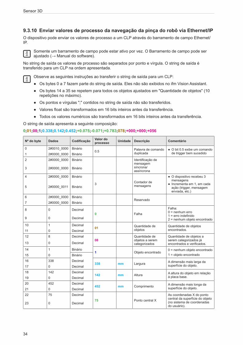
34
9.3.10 Enviar valores de processo da navegação da pinça do robô via Ethernet/IPO dispositivo pode enviar os valores de processo a um CLP através do barramento de campo Ethernet/IP.
Somente um barramento de campo pode estar ativo por vez. O Barramento de campo pode ser ajustado (→ Manual do software).
No string de saída os valores de processo são separados por ponto e vírgula. O string de saída é transferido para um CLP na ordem apresentada.
Observe as seguintes instruções ao transferir o string de saída para um CLP:
● Os bytes 0 a 7 fazem parte do string de saída. Eles não são exibidos no ifm Vision Assistant.
● Os bytes 14 a 35 se repetem para todos os objetos ajustados em "Quantidade de objetos" (10 repetições no máximo).
● Os pontos e vírgulas ";" contidos no string de saída não são transferidos.
● Valores float são transformados em 16 bits inteiros antes da transferência.
● Todos os valores numéricos são transformados em 16 bits inteiros antes da transferência.
O string de saída apresenta a seguinte composição:
0;01;08;1;0.338;0.142;0.452;+0.075;-0.071;+0.783;078;+000;+000;+056
Nº do byte Dados Codificação Valor do processo Unidade Descrição Comentário
0 2#0010_0000 Binário0.5 Palavra de comando
duplicada ● O bit 0.5 exibe um comando de trigger bem sucedido1 2#0000_0000 Binário
2 2#0000_0000 Binário Identificação de mensagem síncrona/ assíncrona
3 2#0000_0000 Binário
4 2#0000_0000 Binário
3 Contador de mensagens
● O dispositivo recebeu 3 mensagens
● Incrementa em 1, em cada ação (trigger, mensagem enviada, etc.)
5 2#0000_0011 Binário
6 2#0000_0000 BinárioReservado
7 2#0000_0000 Binário
8 0 Decimal0 Falha
Falha: 0 = nenhum erro 1 = erro indefinido 2 = nenhum objeto encontrado9 0 Decimal
10 1 Decimal01 Quantidade de
objetosQuantidade de objetos encontrados.11 0 Decimal
12 8 Decimal08
Quantidade de objetos a serem categorizados
Quantidade de objetos a serem categorizados já encontrados e verificados.13 0 Decimal
14 1 Binário1 Objeto encontrado
0 = nenhum objeto encontrado1 = objeto encontrado15 0 Binário
16 338 Decimal338 mm Largura A dimensão mais larga da
superfície do objeto.17 0 Decimal
18 142 Decimal142 mm Altura A altura do objeto em relação
à placa base.19 0 Decimal
20 452 Decimal452 mm Comprimento A dimensão mais longa da
superfície do objeto.21 0 Decimal
22 75 Decimal75 Ponto central X
As coordenadas X do ponto central da superfície do objeto (no sistema de coordenadas do usuário).
23 0 Decimal

35
Sensor 3D
PT
Nº do byte Dados Codificação Valor do processo Unidade Descrição Comentário
24 -71 Decimal-71 Ponto central Y
As coordenadas Y do ponto central da superfície do objeto (no sistema de coordenadas do usuário).
25 0 Decimal
26 783 Decimal783 Ponto central Z
As coordenadas Z do ponto central da superfície do objeto (no sistema de coordenadas do usuário).
27 0 Decimal
28 78 Decimal
078 eixo de guinada
O eixo de guinada está localizado entre o eixo X (sistema internacional de coordenadas) e o vetor ao longo do "comprimento" do objeto.
29 0 Decimal
30 0 Decimal+000 Rotação X
Rotação no eixo X do objeto detectado (no sistema de coordenadas do usuário).31 0 Decimal
32 0 Decimal+000 Rotação Y
Rotação no eixo Y do objeto detectado (no sistema de coordenadas do usuário).33 0 Decimal
34 56 Decimal+056 Rotação Z
Rotação no eixo Z do objeto detectado (no sistema de coordenadas do usuário).35 0 Decimal
A execução incorreta de um comando leva à seguinte condição:
● Bit de falha (error bit) = 1
● A palavra de comando duplicada é exibida
● Bit de mensagens assincrono = 0
● Identificação de mensagem assíncrona = 0
● Contador de mensagens incrementa em 1

Sensor 3D
36
9.3.11 Enviar valores de processo da navegação da pinça do robô via PROFINETO dispositivo pode enviar os valores de processo a um CLP através do barramento de campo PROFINET.
Somente um barramento de campo pode estar ativo por vez. O Barramento de campo pode ser ajustado (→ Manual do software).
No string de saída os valores de processo são separados por ponto e vírgula. O string de saída é transferido para um CLP na ordem apresentada.
Observe as seguintes instruções ao transferir o string de saída para um CLP:
● Os bytes 0 a 7 fazem parte do string de saída. Eles não são exibidos no ifm Vision Assistant.
● Os bytes 14 a 35 se repetem para todos os objetos ajustados em "Quantidade de objetos" (10 repetições no máximo).
● Os pontos e vírgulas ";" contidos no string de saída não são transferidos.
● Valores float são transformados em 16 bits inteiros antes da transferência.
● Todos os valores numéricos são transformados em 16 bits inteiros antes da transferência.
O string de saída apresenta a seguinte composição:
0;01;08;1;0.338;0.142;0.452;+0.075;-0.071;+0.783;078;+000;+000;+056
Nº do byte Dados Codificação Valor do processo Unidade Descrição Comentário
0 2#0010_0000 Binário0.5 Palavra de comando
duplicada ● O bit 0.5 exibe um comando de trigger bem sucedido1 2#0000_0000 Binário
2 2#0000_0000 Binário Identificação de mensagem síncrona/ assíncrona
3 2#0000_0000 Binário
4 2#0000_0000 Binário
3 Contador de mensagens
● O dispositivo recebeu 3 mensagens
● Incrementa em 1, em cada ação (trigger, mensagem enviada, etc.)
5 2#0000_0011 Binário
6 2#0000_0000 BinárioReservado
7 2#0000_0000 Binário
8 0 Decimal0 Falha
Falha: 0 = nenhum erro 1 = erro indefinido 2 = nenhum objeto encontrado9 0 Decimal
10 1 Decimal01 Quantidade de
objetosQuantidade de objetos encontrados.11 0 Decimal
12 8 Decimal08
Quantidade de objetos a serem categorizados
Quantidade de objetos a serem categorizados já encontrados e verificados.13 0 Decimal
14 1 Binário1 Objeto encontrado
0 = nenhum objeto encontrado1 = objeto encontrado15 0 Binário
16 338 Decimal338 mm Largura A dimensão mais larga da
superfície do objeto.17 0 Decimal
18 142 Decimal142 mm Altura A altura do objeto em relação
à placa base.19 0 Decimal
20 452 Decimal452 mm Comprimento A dimensão mais longa da
superfície do objeto.21 0 Decimal
22 75 Decimal75 Ponto central X
As coordenadas X do ponto central da superfície do objeto (no sistema de coordenadas do usuário).
23 0 Decimal

37
Sensor 3D
PT
Nº do byte Dados Codificação Valor do processo Unidade Descrição Comentário
24 -71 Decimal-71 Ponto central Y
As coordenadas Y do ponto central da superfície do objeto (no sistema de coordenadas do usuário).
25 0 Decimal
26 783 Decimal783 Ponto central Z
As coordenadas Z do ponto central da superfície do objeto (no sistema de coordenadas do usuário).
27 0 Decimal
28 78 Decimal
078 Eixo de guinada
O eixo de guinada está localizado entre o eixo X (sistema internacional de coordenadas) e o vetor ao longo do "comprimento" do objeto.
29 0 Decimal
30 0 Decimal+000 Rotação X
Rotação no eixo X do objeto detectado (no sistema de coordenadas do usuário).31 0 Decimal
32 0 Decimal+000 Rotação Y
Rotação no eixo Y do objeto detectado (no sistema de coordenadas do usuário).33 0 Decimal
34 56 Decimal+056 Rotação Z
Rotação no eixo Z do objeto detectado (no sistema de coordenadas do usuário).35 0 Decimal
A execução incorreta de um comando leva à seguinte condição:
● Bit de falha (error bit) = 1
● A palavra de comando duplicada é exibida
● Bit de mensagens assincrono = 0
● Identificação de mensagem assíncrona = 0
● Contador de mensagens incrementa em 1

Sensor 3D
38
9.3.12 Enviar valores de processo da navegação da pinça do robô via TCP/IPO dispositivo pode enviar os valores de processo a um CLP via protocolo TCP/IP. Os valores de processo são exibidos no Vision Assistant ifm como string de saída da seguinte forma:
No string de saída os valores de processo são separados por ponto e vírgula. O string de saída é transferido para um CLP na ordem apresentada.
Observe as seguintes instruções ao transferir o string de saída para um CLP:
● Os pontos e vírgulas ";" contidos no string de saída não são transferidos.
● Os valores de processo desde "objeto encontrado" até "rotação Z" se repetem para todos os objetos ajustados em "Quantidade de objetos" (10 repetições no máximo).
● Todos os valores numéricos são transformados em 16 bits inteiros antes da transferência.
O string de saída apresenta a seguinte composição (tipo de dados: ASCII):
star;0;01;08;1;0.338;0.142;0.452;+0.075;-0.071;+0.783;078;+000;+000;+056;stop
Valor do processo Unidade Descrição
star String de início
0 Falha
01 Quantidade de objetos
08 Quantidade de objetos a serem categorizados
1 0 = nenhum objeto encontrado 1 = objeto encontrado
0.338 mm Largura
0.142 mm Altura
0.452 mm Comprimento
+0.075 Ponto central X
-0.071 Ponto central Y
+0.783 Ponto central Z
078 Eixo de guinada
+000 Rotação X
+000 Rotação Y
+056 Rotação Z
stop String de parada

39
Sensor 3D
PT
9.3.13 Enviar valores de processo da despaletização via Ethernet/IPO dispositivo pode enviar os valores de processo a um CLP através do barramento de campo Ethernet/IP.
Somente um barramento de campo pode estar ativo por vez. O Barramento de campo pode ser ajustado (→ Manual do software).
No string de saída os valores de processo são separados por ponto e vírgula. O string de saída é transferido para um CLP na ordem apresentada.
Observe as seguintes instruções ao transferir o string de saída para um CLP:
● Os bytes 0 a 7 fazem parte do string de saída. Eles não são exibidos no ifm Vision Assistant.
● Os pontos e vírgulas ";" contidos no string de saída não são transferidos.
● Valores float são transformados em 16 bits inteiros antes da transferência.
● Todos os valores numéricos são transformados em 16 bits inteiros antes da transferência.
O string de saída apresenta a seguinte composição:
1;0.200;0.150;0.307;+00.002;-10.044;+03.100;+170;-133;-132;02;1;098;00;1
Nº do byte Dados Codificação Valor do processo Unidade Descrição Comentário
0 2#0010_0000 Binário0.5 Palavra de comando
duplicada ● O bit 0.5 exibe um comando de trigger bem sucedido1 2#0000_0000 Binário
2 2#0000_0000 Binário Identificação de mensagem síncrona/ assíncrona
3 2#0000_0000 Binário
4 2#0000_0000 Binário
3 Contador de mensagens
● O dispositivo recebeu 3 mensagens
● Incrementa em 1, em cada ação (trigger, mensagem enviada, etc.)
5 2#0000_0011 Binário
6 2#0000_0000 BinárioReservado
7 2#0000_0000 Binário
8 1 Binário1 Objeto encontrado
0 = nenhum objeto encontrado1 = objeto encontrado9 0 Binário
10 200 Decimal200 mm Largura A dimensão mais larga da
superfície do objeto.11 0 Decimal
12 150 Decimal150 mm Altura A altura do objeto em relação
à placa base.13 0 Decimal
14 307 Decimal307 mm Comprimento A dimensão mais longa da
superfície do objeto.15 0 Decimal
16 2 Decimal+2 Ponto central X
As coordenadas X do ponto central da superfície do objeto (no sistema de coordenadas do usuário).17 0 Decimal
18 10044 Decimal-10044 Ponto central Y
As coordenadas Y do ponto central da superfície do objeto (no sistema de coordenadas do usuário).19 0 Decimal
20 3100 Decimal+3100 Ponto central Z
As coordenadas Z do ponto central da superfície do objeto (no sistema de coordenadas do usuário).21 0 Decimal
22 170 Decimal+170 Rotação X
Rotação no eixo X do objeto detectado (no sistema de coordenadas do usuário).23 0 Decimal

Sensor 3D
40
Nº do byte Dados Codificação Valor do processo Unidade Descrição Comentário
24 -133 Decimal-133 Rotação Y
Rotação no eixo Y do objeto detectado (no sistema de coordenadas do usuário).25 0 Decimal
26 -132 Decimal-132 Rotação Z
Rotação no eixo Z do objeto detectado (no sistema de coordenadas do usuário).27 0 Decimal
28 02 Decimal02 Nível atual
Nível atual da palete, começando com "0". Um nível vazio é marcada por "0".
29 0 Decimal
30 1 Binário
1 Lâmina de separação
Uma lâmina de separação está em um dos níveis da palete:0 = nenhuma lâmina de separação detectada1 = lâmina de separação detectada
31 0 Binário
32 098 Decimal
098 Falha
Falha: 0 = nenhum erro 1 = erro indefinido 2 = objeto inesperado detectadoOutros códigos de erro: (→ 13.1.5).
33 0 Decimal
34 00 Binário00 Livre de colisão
Despaletizar sem colisão:0: não 1: sim35 0 Binário
36 1 Decimal1 Qualidade
Qualidade de detecção de objeto entre 0 e 100. O valor "100" significa a melhor qualidade possível.37 0 Decimal
A execução incorreta de um comando leva à seguinte condição:
● Bit de falha (error bit) = 1
● A palavra de comando duplicada é exibida
● Bit de mensagens assincrono = 0
● Identificação de mensagem assíncrona = 0
● Contador de mensagens incrementa em 1

41
Sensor 3D
PT
9.3.14 Enviar valores de processo da despaletização via PROFINETO dispositivo pode enviar os valores de processo a um CLP através do barramento de campo PROFINET.
Somente um barramento de campo pode estar ativo por vez. O Barramento de campo pode ser ajustado (→ Manual do software).
No string de saída os valores de processo são separados por ponto e vírgula. O string de saída é transferido para um CLP na ordem apresentada.
Observe as seguintes instruções ao transferir o string de saída para um CLP:
● Os bytes 0 a 7 fazem parte do string de saída. Eles não são exibidos no ifm Vision Assistant.
● Os pontos e vírgulas ";" contidos no string de saída não são transferidos.
● Valores float são transformados em 16 bits inteiros antes da transferência.
● Todos os valores numéricos são transformados em 16 bits inteiros antes da transferência.
O string de saída apresenta a seguinte composição:
1;0.200;0.150;0.307;+00.002;-10.044;+03.100;+170;-133;-132;02;1;098;00;1
Nº do byte Dados Codificação Valor do processo Unidade Descrição Comentário
0 2#0010_0000 Binário0.5 Palavra de comando
duplicada ● O bit 0.5 exibe um comando de trigger bem sucedido1 2#0000_0000 Binário
2 2#0000_0000 Binário Identificação de mensagem síncrona/ assíncrona
3 2#0000_0000 Binário
4 2#0000_0000 Binário
3 Contador de mensagens
● O dispositivo recebeu 3 mensagens
● Incrementa em 1, em cada ação (trigger, mensagem enviada, etc.)
5 2#0000_0011 Binário
6 2#0000_0000 BinárioReservado
7 2#0000_0000 Binário
8 1 Binário1 Objeto encontrado
0 = nenhum objeto encontrado1 = objeto encontrado9 0 Binário
10 200 Decimal200 mm Largura A dimensão mais larga da
superfície do objeto.11 0 Decimal
12 150 Decimal150 mm Altura A altura do objeto em relação
à placa base.13 0 Decimal
14 307 Decimal307 mm Comprimento A dimensão mais longa da
superfície do objeto.15 0 Decimal
16 2 Decimal+2 Ponto central X
As coordenadas X do ponto central da superfície do objeto (no sistema de coordenadas do usuário).17 0 Decimal
18 10044 Decimal-10044 Ponto central Y
As coordenadas Y do ponto central da superfície do objeto (no sistema de coordenadas do usuário).19 0 Decimal
20 3100 Decimal+3100 Ponto central Z
As coordenadas Z do ponto central da superfície do objeto (no sistema de coordenadas do usuário).21 0 Decimal
22 170 Decimal+170 Rotação X
Rotação no eixo X do objeto detectado (no sistema de coordenadas do usuário).23 0 Decimal

Sensor 3D
42
Nº do byte Dados Codificação Valor do processo Unidade Descrição Comentário
24 -133 Decimal-133 Rotação Y
Rotação no eixo Y do objeto detectado (no sistema de coordenadas do usuário).25 0 Decimal
26 -132 Decimal-132 Rotação Z
Rotação no eixo Z do objeto detectado (no sistema de coordenadas do usuário).27 0 Decimal
28 02 Decimal02 Nível atual
Nível atual da palete, começando com "0". Um nível vazio é marcada por "0".
29 0 Decimal
30 1 Binário
1 Lâmina de separação
Uma lâmina de separação está em um dos níveis da palete:0 = nenhuma lâmina de separação detectada1 = lâmina de separação detectada
31 0 Binário
32 098 Decimal
098 Falha
Falha: 0 = nenhum erro 1 = erro indefinido 2 = objeto inesperado detectadoOutros códigos de erro:(→ 13.1.5).
33 0 Decimal
34 00 Binário00 Livre de colisão
Despaletizar sem colisão:0: não 1: sim35 0 Binário
36 1 Decimal1 Qualidade
Qualidade de detecção de objeto entre 0 e 100. O valor "100" significa a melhor qualidade possível.37 0 Decimal
A execução incorreta de um comando leva à seguinte condição:
● Bit de falha (error bit) = 1
● A palavra de comando duplicada é exibida
● Bit de mensagens assincrono = 0
● Identificação de mensagem assíncrona = 0
● Contador de mensagens incrementa em 1

43
Sensor 3D
PT
9.3.15 Enviar valores de processo da despaletização via TCP/IPO dispositivo pode enviar os valores de processo a um CLP via protocolo TCP/IP. Os valores de processo são exibidos no Vision Assistant ifm como string de saída da seguinte forma:
No string de saída os valores de processo são separados por ponto e vírgula. O string de saída é transferido para um CLP na ordem apresentada.
Observe as seguintes instruções ao transferir o string de saída para um CLP:
● Os pontos e vírgulas ";" contidos no string de saída não são transferidos.
● Todos os valores numéricos são transformados em 16 bits inteiros antes da transferência.
O string de saída apresenta a seguinte composição (tipo de dados: ASCII):
star;1;0.200;0.150;0.307;+00.002;-10.044;+03.100;+170;-133;-132;02;1;098;00;1;stop
Valor do processo Unidade Descrição
star String de início
1 0 = nenhum objeto encontrado 1 = objeto encontrado
0.200 Largura
0.150 Altura
0.307 Comprimento
+00.002 Ponto central X
-10.044 Ponto central Y
+03.100 Ponto central Z
+170 Rotação X
-133 Rotação Y
-132 Rotação Z
02 Nível atual
10 = nenhuma lâmina de separação detectada 1 = lâmina de separação detectada
098 Falha
00 0 = nenhuma despaletização sem colisão 1 = despaletização sem colisão
1 Qualidade de detecção de objeto (0 a 100)
stop String de parada

Sensor 3D
44
10. Manutenção, conservação e descarteObservar as seguintes instruções:
► Não abrir o equipamento. Não existem componentes no interior do equipamento que possam ser consertados pelo usuário. A reparação do equipamento só pode ser realizada pelo fabricante.
► Descartar o equipamento de acordo com as normais ambientais nacionais vigentes.
10.1 LimpezaObserve as seguintes instruções antes de limpar o equipamento:
► Utilizar um pano limpo e sem fiapos.
► Utilizar limpador de vidro como agente de limpeza.
Se as instruções não forem respeitadas, podem ocorrer erros de medição devido a arranhões no visor frontal.
10.2 Atualizar o firmwareCom o software ifm Vision Assistant pode-se fazer a atualização do firmware do equipamento.
Os parâmetros salvos no equipamento são perdidos quando o firmware é atualizado. Crie uma cópia de segurança dos parâmetros antes de atualizar o firmware:
► Exportar os parâmetros antes da atualização do firmware.
► Importar os parâmetros após a atualização do firmware.
Atualizações de firmware estão disponíveis na internet: www.ifm.com
10.3 Substituir o equipamentoQuando um equipamento é substituído, os parâmetros são perdidos. Crie uma cópia de segurança dos parâmetros antes de substituir o equipamento:
► Exportar os parâmetros do equipamento antigo antes da substituição.
► Importar os parâmetros para o novo equipamento após a substituição.
Com a exportação e importação de parâmetros, pode-se carregar rapidamente vários equipamentos com os mesmo parâmetros.
11. Autorizações/normasA declaração de conformidade CE está disponível em: www.ifm.com
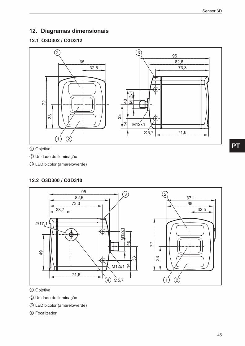
45
Sensor 3D
PT
12. Diagramas dimensionais12.1 O3D302 / O3D312
Original Scale Drawing (MTD)
EPS SourceProduct Scale DrawingFrame Size: 80 mm x 45 mm
P_MZ_200_0359
O3D302O3D303O3D312O3D313
33
3
5,7M
12x1
4014
9582,6
73,3
71,6
72
6532,5
21
332
M12x133
3
5,7
M12
x140
14
9582,6
73,3
71,6
72
6532,5
21
33
2
M12x1
① Objetiva
② Unidade de iluminação
③ LED bicolor (amarelo/verde)
12.2 O3D300 / O3D310
Original Scale Drawing (MTD)
EPS SourceProduct Scale DrawingFrame Size: 80 mm x 45 mm
P_MZ_200_0362
O3D300O3D301O3D310O3D311
33
3
5,7
M12
x140
14
9582,6
73,3
71,6
49
17,1
28,7
4
M12x1
72
6532,5
2
21
33
67,1
33
3
5,7
M12
x140
14
9582,6
73,3
71,6
49
17,1
28,7
4
M12x1
72
6532,5
2
21
33
67,1
① Objetiva
② Unidade de iluminação
③ LED bicolor (amarelo/verde)
④ Focalizador

Sensor 3D
46
13. Appendix13.1 Process InterfaceThe process interface is used during the normal operation mode to get operational data (e.g. 3D images, process values) from the O3D3xx.
13.1.1 Sending CommandsFor sending commands via the process interface the commands have to be sent with a special protocol and as ASCII character strings. This protocol conforms to the version 3 of the O2V/O2D products.
Structure of the protocol:
<Ticket><length>CR LF <Ticket><content>CR LF
Abbreviation Description ASCII code (dec) ASCII code (hex)
CR Carriage Return 13 DLF Linefeed 10 A< > Marking of a placeholder
(e.g. <code> is a placeholder for code)[ ] Optional argument
(possible but not required)
Command Description
<content> It is the command to the device (e.g. trigger the unit).<ticket> It is a character string of 4 digits between 0-9. If a message with a specific ticket is sent
to the device, it will reply with the same ticket.
A ticket number must be > 0999. Use a ticket number from the range 1000 - 9999.
<length> It is a character string beginning with the letter 'L' followed by 9 digits. It indicates the length of the following data (<ticket><content>CR LF) in bytes.
They are different protocol versions available:
Version Input format Output format
V1 <Content>CR LF As input V2 <Ticket><Content>CR LF As input V3 <Ticket><Length>CR LF<Ticket><Content>CR LF As input V4 <Content>CR LF <length>CR LF<Content>CR LF
The default protocol version is "V3". It is recommended to use protocol version 3 for machine to machine communication. This is due to the fact that only version 3 supports asynchronous messages and provides length information.
Ticket numbers for asynchronous messages:
Ticket number Description
0000 Asynchronous results0001 Asynchronous error messages / codes0010 Asynchronous notifications / message codes

47
Sensor 3D
PT
Format of asynchronous notifications
The format of the asynchronous notifications is a combination of the unique message ID and a JSON formatted string containing the notification details: <unique message ID>:<JSON content>
Example for protocol version 3:
<ticket=0010>L<length>CR LF<ticket=0010><unique message ID>:<JSON content>CR LF
Result:
0010L000000045\r\n0010000500000:{"ID": 1034160761,"Index":1,"Name": "Pos 1"}\r\n
Explanation of the result:
Command Result
<ticket=0010> 0010L<length> L000000045CR LF \r\n<ticket=0010> 0010<unique message ID> 000500000<JSON content> {"ID": 1034160761,"Index":1,"Name": "Pos 1"}CR LF \r\n
Asynchronous message IDs
Asynchronous message ID
Description Example Description
000500000 Application changed
{"ID": 1034160761,"Index":1,"Name": "Pos 1","valid":true}
000500001 Application is not valid
{"ID": 1034160761,"Index":1,"Name": "Pos 1","valid":false}
If a application exists on given index but it is invalid, the ID and Name are filled accoring to the application. If there is no application on given index, the application ID will contain 0 and the name an empty string "".
000500002 image acquisition finished
{} This message signals the reciever, that the device has finished the image acquistion. This can be used for cascading multiple devices with a software trigger.
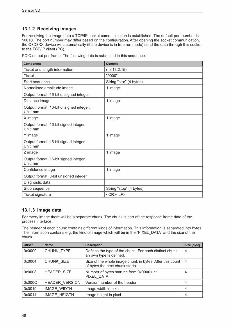
Sensor 3D
48
13.1.2 Receiving ImagesFor receiving the image data a TCP/IP socket communication is established. The default port number is 50010. The port number may differ based on the configuration. After opening the socket communication, the O3D3XX device will automatically (if the device is in free run mode) send the data through this socket to the TCP/IP client (PC).
PCIC output per frame. The following data is submitted in this sequence:
Component Content
Ticket and length information (→ 13.2.15)Ticket "0000"Start sequence String "star" (4 bytes)Normalised amplitude image
Output format: 16-bit unsigned integer
1 image
Distance image
Output format: 16-bit unsigned integer. Unit: mm
1 image
X image
Output format: 16-bit signed integer. Unit: mm
1 image
Y image
Output format: 16-bit signed integer. Unit: mm
1 image
Z image
Output format: 16-bit signed integer. Unit: mm
1 image
Confidence image
Output format: 8-bit unsigned integer
1 image
Diagnostic dataStop sequence String "stop" (4 bytes)Ticket signature <CR><LF>
13.1.3 Image dataFor every image there will be a separate chunk. The chunk is part of the response frame data of the process interface.
The header of each chunk contains different kinds of information. This information is separated into bytes. The information contains e.g. the kind of image which will be in the “PIXEL_DATA” and the size of the chunk.
Offset Name Description Size [byte]
0x0000 CHUNK_TYPE Defines the type of the chunk. For each distinct chunk an own type is defined.
4
0x0004 CHUNK_SIZE Size of the whole image chunk in bytes. After this count of bytes the next chunk starts.
4
0x0008 HEADER_SIZE Number of bytes starting from 0x0000 until PIXEL_DATA.
4
0x000C HEADER_VERSION Version number of the header 40x0010 IMAGE_WIDTH Image width in pixel 40x0014 IMAGE_HEIGTH Image height in pixel 4

49
Sensor 3D
PT
Offset Name Description Size [byte]
0x0018 PIXEL_FORMAT Pixel format 40x001C TIME_STAMP Time stamp in microseconds (deprecated) 40x0020 FRAME_COUNT Frame counter 40x0024 STATUS_CODE Errors of the device 40x0028 TIME_STAMP_SEC Time stamp in seconds 40x002C TIME_STAMP_NSEC Time stamp in nanoseconds 40x0030 PIXEL_DATA The pixel data in the given type and dimension of the
image. Padded to 4-byte boundary.4
Available chunk types:
Constant Value Description
RADIAL_DISTANCE_IMAGE
100 Each pixel of the distance matrix denotes the ToF distance measured by the corresponding pixel or group of pixels of the imager. The distance value is corrected by the camera's calibration, excluding effects caused by multipath and multiple objects contributions (e.g. "flying pixels"). Reference point is the optical centre of the camera inside the camera housing.
Invalid PMD pixels (e.g. due to saturation) have a value of zero.
Data type: 16-bit unsigned integer (little endian)
Unit: millimetresNORM_AMPLITUDE_IMAGE
101 Each pixel of the normalized amplitude image denotes the raw amplitude (see amplitude image below for further explanation), normalized to exposure time. Furthermore, vignetting effects are compensated, ie the darkening of pixels at the image border is corrected. The visual impression of this grayscale image is comparable to that of a common 2D camera.
Invalid PMD pixels (e.g. due to saturation) have an amplitude value of 0.
Data type: 16-bit unsigned integerAMPLITUDE_IMAGE 103 Each pixel of the amplitude matrix denotes the amount of
modulated light (i.e. the light from the camera's active illumination) which is reflected by the appropriate object. Higher values indicate higher PMD signal strengths and thus a lower amount of noise on the corresponding distance measurements. The amplitude value is directly derived from the PMD phase measurements without normalisation to exposure time. In multiple exposure mode, the lack of normalisation may lead (depending on the chosen exposure times) to inhomogeneous amplitude image impression, if a certain pixel is taken from the short exposure time and some of its neighbours are not.
Invalid PMD pixels (e.g. due to saturation) have an amplitude value of 0.
Data type: 16-bit unsigned integerGRAYSCALE_IMAGE 104 Each pixel of the amplitude matrix denotes the amount of
modulated light which is reflected by the appropriate object (i.e. the light from the camera's active illumination). Higher values indicate higher PMD signal strengths and thus a lower amount of noise on the corresponding distance measurements. The amplitude value is directly derived from the PMD phase measurements without normalisation to exposure time.

Sensor 3D
50
Constant Value Description
CARTESIAN_X_COMPONENT
200 The X matrix denotes the X component of the Cartesian coordinate of a PMD 3D measurement. The origin of the camera's coordinate system is in the middle of the lens' front glass, if the extrinsic parameters are all set to 0.
Data type: 16-bit signed integer
Unit: millimetresCARTESIAN_Y_COMPONENT
201 The Y matrix denotes the Y component of the Cartesian coordinate of a PMD 3D measurement. The origin of the camera's coordinate system is in the middle of the lens' front glass, if the extrinsic parameters are all set to 0.
Data type: 16-bit signed integer
Unit: millimetresCARTESIAN_Z_COMPONENT
202 The Z matrix denotes the Z component of the Cartesian coordinate of a PMD 3D measurement. The origin of the camera's coordinate system is in the middle of the lens' front glass, if the extrinsic parameters are all set to 0.
Data type: 16-bit signed integer
Unit: millimetresCARTESIAN_ALL 203 CARTESIAN_X_COMPONENT,
CARTESIAN_Y_COMPONENT, CARTESIAN_Z_COMPONENT
UNIT_VECTOR_ALL 223 The unit vector matrix contains 3 values [ex, ey, ez] for each PMD pixel, i.e. the data layout is [ex_1,ey_1,ez_1, ... ex_N, ey_N, ez_N], where N is the number of PMD pixels.
Data type: 32-bit floating point number (3x per pixel)CONFIDENCE_IMAGE 300 See Additional Information for Image Data (→ 13.1.4)DIAGNOSTIC 302 See Receiving Images (→ 13.1.2)JSON_DIAGNOSTIC 305 Items with JSON formatted diagnostic data is formated like this:
{
"AcquisitionDuration": 20.391,
"EvaluationDuration": 37.728,
"FrameDuration": 37.728,
"FrameRate": 15.202,
"TemperatureIllu": 52.9
}
Unit for durations: millimetres
Unit for framerates: Hz
Unit for temperature: °C

51
Sensor 3D
PT
Constant Value Description
EXTRINSIC_CALIB 400 The transformation from one cartesian coordinate system to another is defined by a 6 degrees of freedom vector (DOF): [trans_x, trans_y, trans_z, rot_x, rot_y, rot_z]. Let R be the product of the common "clockwise" 3D-rotation matrices: R = Rx*Ry*Rz
The transformation of a point P is specified by P_t = R*P + [trans_x, trans_y, trans_z]'.
The device extrinisic calibration can be set by the user, but it may be changed by an automatic calibration feature of the device.
Data type: 32-bit floating point number (little endian)
Unit for trans_x, trans_y, trans_z: millimetres
Unit for rot_x, rot_y, rot_z: °JSON_MODEL 500 Model data in JSONMODEL_ROIMASK 501 ROI mask for internal debugging purposesSNAPSHOT_IMAGE 600 Snapshot image
Pixel format:
Constant Value Description
FORMAT_8U 0 8-bit unsigned integerFORMAT_8S 1 8-bit signed integerFORMAT_16U 2 16-bit unsigned integerFORMAT_16S 3 16-bit signed integerFORMAT_32U 4 32-bit unsigned integerFORMAT_32S 5 32-bit signed integerFORMAT_32F 6 32-bit floating point numberFORMAT_64U 7 64-bit unsigned integerFORMAT_64F 8 64-bit floating point numberReserved 9 N/AFORMAT_32F_3 10 Vector with 3x32-bit floating point number

Sensor 3D
52
13.1.4 Additional Information for CONFIDENCE_IMAGEFurther information for the confidence image:
Bit Value Description
0 1 = pixel invalid Pixel invalid
The pixel is invalid. To determine whether a pixel is valid or not only this bit needs to be checked. The reason why the bit is invalid is recorded in the other confidence bits.
1 1 = pixel saturated Pixel is saturated
Contributes to pixel validity: yes2 1 = bad A-B symmetry A-B pixel symmetry
The A-B symmetry value of the four phase measurements is above threshold.
Remark: This symmetry value is used to detect motion artefacts. Noise (e.g. due to strong ambient light or very short integration times) or PMD interference may also contribute.
Contributes to pixel validity: yes3 1 = amplitude below
minimum amplitude threshold
Amplitude limits
The amplitude value is below minimum amplitude threshold.
Contributes to pixel validity: yes4+5 Bit 5, bit 4
0 0 = unused
0 1 = shortest exposure time (only used in 3 exposure mode)
1 0 = middle exposure time in 3 exposure mode, short exposure in double exposure mode
1 1 = longest exposure time (always 1 in single exposure mode)
Exposure time indicator
The two bits indicate which exposure time was used in a multiple exposure measurement.
Contributes to pixel validity: no
6 1 = pixel is clipped Clipping box on 3D data
If clipping is active this bit indicates that the pixel coordinates are outside the defined volume.
Contributes to pixel validity: yes7 1 = suspect/defective pixel Suspect pixel
This pixel has been marked as "suspect" or "defective" and values have been replaced by interpolated values from the surroundings.
Contributes to pixel validity: no

53
Sensor 3D
PT
13.1.5 Configuration of PCIC OutputThe user has the possibility to define his own PCIC output. This configuration is only valid for the current PCIC connection. It does not affect any other connection and will get lost after disconnecting.
For configuring the PCIC output a “flexible” layouter concept is used, represented by a JSON string. The format of the default configuration is as follows:
{
"layouter": "flexible",
"format": { "dataencoding": "ascii" },
"elements": [
{ "type": "string", "value": "star", "id": "start_string" },
{ "type": "blob", "id": "normalized_amplitude_image" },
{ "type": "blob", "id": "x_image" },
{ "type": "blob", "id": "y_image" },
{ "type": "blob", "id": "z_image" },
{ "type": "blob", "id": "confidence_image" },
{ "type": "blob", "id": "diagnostic_data" },
{ "type": "string", "value": "stop", "id": "end_string" }
]
}
This string can be retrieved by the C? command, altered and sent back using the c command.
The layout software has the following main object properties:
Name Description Details
layouter Defines the basic data output format.
So far only “flexible” is supported
Type: string
format Defines format details, the definitions in the main object are the defaults for any of the following data elements (e.g. if it says dataencoding=binary, all data elements should be binary encoded instead of ASCII).
Type: object
elements List of data elements which must be written. Type: array of objects
The actual data is defined within the “elements” properties and may consist of these settings:
Name Description Details
type Defines the type of data which must be written.
The data might be stored in a different type (e.g. stored as integer but should be output as Float32)
The type "records" will need some special handling.
Type: string
id Defines an identifier for this data element.
If there is no fixed value (property "value"), the data should be retrieved via id.
Type: string
value Optional property for defining a fixed output value. Type: any JSON valueformat Type-depending option for fine-tuning the output format.
E.g. cut an integer to less than 4 bytes.
Type: object

Sensor 3D
54
Available values for the type property:
Type Description
records Defines that this element represents a list of records.
If type is set to "records", there must be an "elements" property.
The "elements" property defines which data should be written per record.string Data is written as string.
Most of the time this will be used with "value" property to write fixed start, end or delimiter text.
Text encoding should be UTF8 if there is nothing else specified in format properties.float32 Data is written as floating point number.
This has a lot of formatting options (at least with "flexible" layout software)
See following section about format properties.uint32 Data is written as integer.
This has a lot of formatting options (at least with "flexible" layout software)
See following section about format properties.int32 Data is written as integer.
This has a lot of formatting options (at least with "flexible" layout software)
See following section about format properties.uint16 Limits the output to two bytes in binary encoding, besides the binary limitation it acts like
uint32.int16 Limits the output to two bytes in binary encoding, besides the binary limitation it acts like
int32.uint8 Limits the output to one byte in binary encoding, besides the binary limitation it acts like
uint32.int8 Limits the output to one byte in binary encoding, besides the binary limitation it acts like
int32.blob Data is written as a BLOB (byte by byte as if it came from the data provider).
(Binary Large Object)
Depending on the desired data format the user may tune his output data with further “format” properties.
Common format properties:
Format properties
Allowed values Default
dataencoding "ascii" or "binary" can be defined in top-level-object and overwritten by element objects.
"ascii"
scale "float value with decimal separator" to scale the results for output byte width
1.0
offset "float value with decimal separator" 0.0
Binary format properties:
Format properties Allowed values Default
order Little, big and network Little

55
Sensor 3D
PT
ASCII format properties:
Format properties Allowed values Default
width Output width. If the resulting value exceeds the width field the result will not be truncated.
0
fill Fill character " "precision Precision is the number of digits behind the decimalseparator. 6 displayformat Fixed, scientific Fixedalignment Left, right Rightdecimalseparator 7-bit characters for e.g. "." "."base Defines if the output should be:
● binary (2)
● octal (8)
● decimal (10)
● hexadecimal (16)
10
Example of a format configuration of the temperature (id: temp_illu) element.
1. Illumination temperature like this "33,5___":
c000000226{ "layouter": "flexible", "format": { "dataencoding": "ascii" }, "elements": [ { "type": "float32", "id": "temp_illu", "format": { "width": 7, "precision": 1, "fill": "_", "alignment": "left", "decimalseparator": "," } } ] }
2. Illumination temperature as binary (16-bit integer, 1/10 °C):
c000000194{ "layouter": "flexible", "format": { "dataencoding": "ascii" }, "elements": [ { "type": "int16", "id": "temp_illu", "format": { "dataencoding": "binary", "order": "network", "scale": 10 } } ] }
3. Illumination temperature in °F (e.g. "92.3 Fahrenheit" ):
c000000227{ "layouter": "flexible", "format": { "dataencoding": "ascii" }, "elements": [ { "type": "float32", "id": "temp_illu", "format": { "precision": 1, "scale": 1.8, "offset": 32 } }, { "type": "string", "value": " Fahrenheit" } ] }

Sensor 3D
56
The following element IDs are available:
ID Description Native data type
activeapp_id Active application, shows which of the 32 application-configurations is currently active
32-bit unsigned integer
all_cartesian_vector_matrices
All Cartesian images (X+Y+Z) concatenated to one package
16-bit signed integer
all_unit_vector_matrices Matrix of unit vectors. Each element consists of a 3 component vector [e_x, e_y, e_z]
Float32
amplitude_image PMD raw amplitude image 16-bit unsigned integer
confidence_image Confidence image 8-bit unsigned integer
distance_image Radial distance image 16-bit unsigned integer unit: millimetres
evaltime Evaluation time for current frame in milliseconds 32-bit unsigned integer
extrinsic_calibration Extrinsic calibration, constisting of 3 translation parameters (unit: millimeters) and 3 angles (unit: degree): [t_x, t_y, t_z, alpha_x, alpha_y, alpha_z]
Float32
framerate Current frame rate in Hz Float32normalized_amplitude_image
Normalized amplitude image 16-bit unsigned integer
temp_front1 Invalid temperature, the output is 3276.7 Float32, unit: °Ctemp_illu Temperature measured in the device while capturing this
result
Measured on the illumination board
Float32, unit: °C
x_image y_image z_image
Cartesian coordinates for each pixel Each dimension is a separate image
16-bit signed integer

57
Sensor 3D
PT
For completeness, level, distance and dimensioning application the following IDs are available:
ID Description Native data type
id ID of the model int32rois.count Number of records in "roi" int32rois List of all ROIs (ROIgroup) of this model recordsSP1
SP2
SwitchingPoint1 and 2 if the model is a Level- or Distance-type. If it is not a Level-/Distance-type, it shall output a null-value.
float32
boxFound
length
width
height
qualityLength
qualityWidth
qualityHeight
xMidTop
yMidTop
zMidTop
yawAngle
backgroundPlaneDistance
These results are available for a dimensioning application. If the model is not oft the type dimensioning, the IDs shall output a null-value.
int8
float
float
float
float
float
float
float
float
float
float
floatnumGood
numUnderSP1
numOverSP2
numInvalid
allROIsGood
anchorFound
hasAnchorTracking
These results are available for a completeness, level and distance applications. If the model is not oft one of these types, the IDs shall output a null-value.
int
int
int
int
bool
bool
bool
For ROIs of completeness, level or distance application the following IDs are available:
ID Description Native data type
id unique ID of the ROI within the Model int32procval per ROI process value float 32Bitstate per ROI state ( if ROI procval is valid or not)
• ROI_PROCESS_VALUE_VALID = 0
• ROI_PROCESS_VALUE_REFIMAGE_SET_NOT_TEACHED = 1
• ROI_PROCESS_VALUE_TEACHING_FAILED = 2
• ROI_PROCESS_VALUE_REFIMAGE_INVALID = 3
• ROI_PROCESS_VALUE_NO_VALID_PIXEL = 4
• ROI_PROCESS_VALUE_REFIMAGE_NO_VALID_PIXEL = 5
• ROI_PROCESS_VALUE_OVERFILL = 6
• ROI_PROCESS_VALUE_UNDERFILL = 7
uint32
quality 0..1 float32

Sensor 3D
58
For the main object on devices with statistics feature the following IDs are available:
ID Description Native data type
statistics_overall_count Allows the user to output the statistics value with the result of the frame, maps to ModelResults:
adv_statistics.number_of_frames
uint32
statistics_passed_count Allows the user to output the statistics value with the result of the frame, maps to ModelResults:
adv_statistics.number_of_passed_frames
uint32
statistics_failed_count Allows the user to output the statistics value with the result of the frame, maps to ModelResults:
adv_statistics.number_of_failed_frames
uint32
statistics_aborted_count Allows the user to output the statistics value with the result of the frame, maps to ModelResults:
adv_statistics.number_of_aborted_frames
uint32
statistics_acquisition_time_min Allows the user to output the statistics value with the result of the frame,maps to ModelResults:
adv_statistics.frame_acquisition.min
float32
statistics_acquisition_time_mean Allows the user to output the statistics value with the result of the frame,maps to ModelResults:
adv_statistics.frame_acquisition.mean
float32
statistics_acquisition_time_max Allows the user to output the statistics value with the result of the frame,maps to ModelResults:
adv_statistics.frame_acquisition.max
float32
statistics_evaluation_time_min Allows the user to output the statistics value with the result of the frame,maps to ModelResults:
adv_statistics.frame_evaluation.min
float32
statistics_evaluation_time_mean Allows the user to output the statistics value with the result of the frame,maps to ModelResults:
adv_statistics.frame_evaluation.mean
float32
statistics_evaluation_time_max Allows the user to output the statistics value with the result of the frame,maps to ModelResults:
adv_statistics.frame_evaluation.max
float32
statistics_frame_duration_min Allows the user to output the statistics value with the result of the frame,maps to ModelResults:
adv_statistics.frame_duration.min
float32
statistics_frame_duration_mean Allows the user to output the statistics value with the result of the frame,maps to ModelResults:
adv_statistics.frame_duration.mean
float32
statistics_frame_duration_max Allows the user to output the statistics value with the result of the frame,maps to ModelResults:
adv_statistics.frame_duration.max
float32
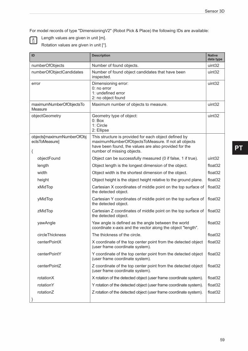
59
Sensor 3D
PT
For model records of type "DimensioningV2" (Robot Pick & Place) the following IDs are available:
Length values are given in unit [m].
Rotation values are given in unit [°].
ID Description Native data type
numberOfObjects Number of found objects. uint32numberOfObjectCandidates Number of found object candidates that have been
inspected.uint32
error Dimensioning error: 0: no error 1: undefined error 2: no object found
uint32
maximumNumberOfObjectsTo Measure
Maximum number of objects to measure. uint32
objectGeometry Geometry type of object: 0: Box 1: Circle 2: Ellipse
uint32
objects[maximumNumberOfObjectsToMeasure] {
objectFound
length
width
height
xMidTop
yMidTop
zMidTop
yawAngle
circleThickness
centerPointX
centerPointY
centerPointZ
rotationX
rotationY
rotationZ
}
This structure is provided for each object defined by maximumNumberOfObjectsToMeasure. If not all objects have been found, the values are also provided for the number of missing objects.
Object can be successfully measured (0 if false, 1 if true).
Object length is the longest dimension of the object.
Object width is the shortest dimension of the object.
Object height is the object height relative to the ground plane.
Cartesian X coordinates of middle point on the top surface of the detected object.
Cartesian Y coordinates of middle point on the top surface of the detected object.
Cartesian Z coordinates of middle point on the top surface of the detected object.
Yaw angle is defined as the angle between the world coordinate x-axis and the vector along the object "length".
The thickness of the circle.
X coordinate of the top center point from the detected object (user frame coordinate system).
Y coordinate of the top center point from the detected object (user frame coordinate system).
Z coordinate of the top center point from the detected object (user frame coordinate system).
X rotation of the detected object (user frame coordinate system).
Y rotation of the detected object (user frame coordinate system).
Z rotation of the detected object (user frame coordinate system).
uint32
float32
float32
float32
float32
float32
float32
float32
float32
float32
float32
float32
float32
float32
float32

Sensor 3D
60
ID Description Native data type
boxFound
length
width
height
xMidTop
yMidTop
zMidTop
yawAngle
circleThickness
centerPointX
centerPointY
centerPointZ
rotationX
rotationY
rotationZ
For compatibility reasons the following values are provided for the first detected object.
Object can be successfully measured (0 if false, 1 if true).
Object length is the longest dimension of the object.
Object width is the shortest dimension of the object.
Object height is the object height relative to the ground plane.
Cartesian X coordinates of middle point on the top surface of the detected object.
Cartesian Y coordinates of middle point on the top surface of the detected object.
Cartesian Z coordinates of middle point on the top surface of the detected object.
Yaw angle is defined as the angle between the world coordinate x-axis and the vector along the object "length".
The thickness of the circle.
X coordinate of the top center point from the detected object (user frame coordinate system).
Y coordinate of the top center point from the detected object (user frame coordinate system).
Z coordinate of the top center point from the detected object (user frame coordinate system).
X rotation of the detected object (user frame coordinate system).
Y rotation of the detected object (user frame coordinate system).
Z rotation of the detected object (user frame coordinate system).
uint32
float32
float32
float32
float32
float32
float32
float32
float32
float32
float32
float32
float32
float32
float32backgroundPlaneDistance
objectType
Distance of the background at background teach.
Type of the detected object: 1: box 2: true bounding box 3: circle 4: enclosing circle 5: ellipse 6: enclosing ellipse
float32
uint32
UFCThreeMarkerTeach["A"..."C"]
{
x
y
}
Coordinates of the available UFC markers.
float32
float32

61
Sensor 3D
PT
For model records of type "Depalletizing" the following IDs are available:
Length values are given in unit [m].
Rotation values are given in unit [°].
ID Description Native data type
error Errors in the algorithm: Value Name Description
0 Depalletizing_Error_None No error detected.
1 Depalletizing_Error_Unknown Unknown error detected.
2 Depalletizing_Error_UnexpectedObject
Unexpected object detected.
3 Depalletizing_Error_StackEmpty Stack is empty.
4 Depalletizing_Error_NoObjectSizes No box dimensions provided on the input.
5 Depalletizing_Error_NoObjectMatch No matching object found.
6 Depalletizing_Error_DataInvalid Too many pixels are invalid.
7 Depalletizing_Error_Background TeachingStatus_ErrorNot EnoughValidPixels
Background estimation only: not enough valid pixels.
8 Depalletizing_Error_Background TeachingStatus_ErrorStdTooHigh
Background estimation only: standard deviation too high.
9 Depalletizing_Error_Background TeachingStatus_ErrorPlaneFitFailed
Background estimation only: estimation of the plane failed.
10 Depalletizing_Error_Background TeachingStatus_ErrorPlane AngleTooHigh
Background estimation only: plane angle too high.
11 Depalletizing_Error_Background TeachingStatus_ErrorRotation CalculationFailed
Background estimation only: internal numerical error in calculation of rotation.
12 Depalletizing_Error_InvalidReferenceTeach
Invalid background teach.
13 Depalletizing_Error_InvalidVOITeach
Invalid VOI teach.
14 Depalletizing_Error_Insufficient MarginToImageBorder
Not enough space between segmented layer and image border.
15 Depalletizing_Error_IncorrectObjectSizes
Provided box dimensions are invalid.
16 Depalletizing_Error_Underfill Measurements are below the background level.
uint32
objectFound Object can be successfully measured (0 if false, 1 if true). uint32objectQuality Quality of the object detection between 0 and 100. float32objectLength Object length is the longest dimension of the top surface of the object. float32objectWidth Object width is the shortest dimension of the top surface of the object. float32objectHeight Object height is the object height relative to the ground plane. float32centerPointX X coordinate of the top center point from the detected object (user frame
coordinate system).float32
centerPointY Y coordinate of the top center point from the detected object (user frame coordinate system).
float32
centerPointZ Z coordinate of the top center point from the detected object (user frame coordinate system).
float32
rotationX X rotation of the detected object (user frame coordinate system). float32rotationY Y rotation of the detected object (user frame coordinate system). float32
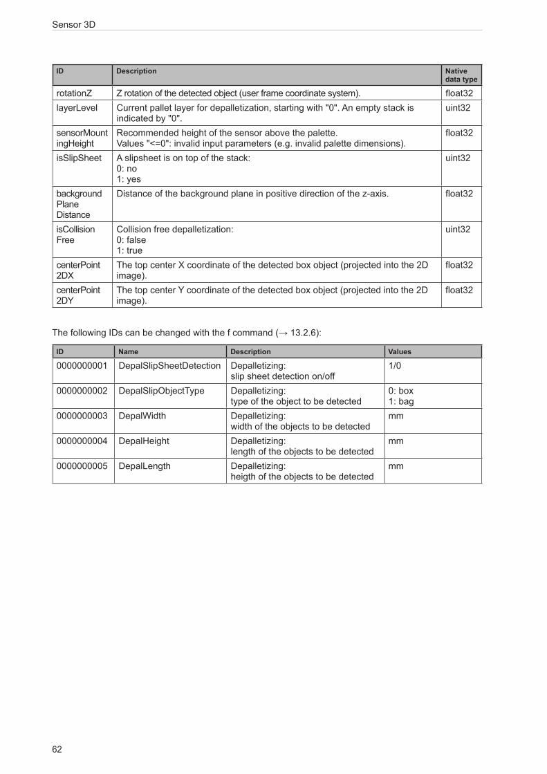
Sensor 3D
62
ID Description Native data type
rotationZ Z rotation of the detected object (user frame coordinate system). float32layerLevel Current pallet layer for depalletization, starting with "0". An empty stack is
indicated by "0".uint32
sensorMount ingHeight
Recommended height of the sensor above the palette. Values "<=0": invalid input parameters (e.g. invalid palette dimensions).
float32
isSlipSheet A slipsheet is on top of the stack: 0: no 1: yes
uint32
background Plane Distance
Distance of the background plane in positive direction of the z-axis. float32
isCollision Free
Collision free depalletization: 0: false 1: true
uint32
centerPoint 2DX
The top center X coordinate of the detected box object (projected into the 2D image).
float32
centerPoint 2DY
The top center Y coordinate of the detected box object (projected into the 2D image).
float32
The following IDs can be changed with the f command (→ 13.2.6):
ID Name Description Values
0000000001 DepalSlipSheetDetection Depalletizing: slip sheet detection on/off
1/0
0000000002 DepalSlipObjectType Depalletizing: type of the object to be detected
0: box 1: bag
0000000003 DepalWidth Depalletizing: width of the objects to be detected
mm
0000000004 DepalHeight Depalletizing: length of the objects to be detected
mm
0000000005 DepalLength Depalletizing: heigth of the objects to be detected
mm

63
Sensor 3D
PT
13.2 Process Interface Command ReferenceAll received messages which are sent because of the following commands will be sent without “start”/”stop” at the beginning or ending of the string.
13.2.1 a Command (activate application)
Command a<application number>
Description Activates the selected application
Type ActionReply *
! ● Application not available
● <application number> contains wrong value
● External application switching activated
● Device is in an invalid state for this command, e.g. configuration mode
? Invalid command lengthNote <application number>
2 digits for the application number as decimal value
13.2.2 A? Command (occupancy of application list)Command A?
Description Requests the occupancy of the application list
Type RequestReply <amount><t><number active
application><t>
...
<number><t><number>? Invalid command length! Invalid state (e.g. no application
active)Note <amount>
char string with 3 digits for the amount of applications saved on the device as decimal number
<t>
tabulator (0x09)
<number active application>
2 digits for the active application
<number>
2 digits for the application number
The active application is repeated within the application list.

Sensor 3D
64
13.2.3 c Command (upload PCIC output configuration)
Command c<length><configuration>
Description Uploads a PCIC output configuration lasting this session
Type ActionReply *
! ● Error in configuration
● Wrong data length? Invalid command length
Note <length>
9 digits as decimal value for the data length
<configuration>
configuration data
13.2.4 C? Command (retrieve current PCIC configuration)Command C?
Description Retrieves the current PCIC configuration
Type RequestReply <length><configuration>
? Invalid command lengthNote <length>
9 digits as decimal value for the data length
<configuration>
configuration data
13.2.5 E? Command (request current error state)Command E?
Description Requests the current error stateType RequestReply <code>
! Invalid state (e.g. configuration mode)? Invalid command length
Note ● <code> Error code with 8 digits as a decimal value. It contains leading zeros.

65
Sensor 3D
PT
13.2.6 f Command (set temporary application parameter)Command f<Parameter-ID>
<reserved><value>
Description Set temporary application parameter<Parameter-id> Id of parameter to be set
Fixed 5 bytes decimal ASCII padded with "0", e.g. "00003".
<reserved> Fixed to "#00000"<value> Fixed 5 bytes signed decimal ASCII
padded with "0" and sign, e.g. "+00777"Type ActionReply * Parameter successfully set
! Parameter-id invalid or syntax error? Invalid command length
Note Example:
f00003#00000+00777

Sensor 3D
66
13.2.7 G? Command (request device information)Command G?
Description Requests device informationType RequestReply <vendor><t><article number><t>
<name><t><location><t><description><t><ip>
<subnet mask><t><gateway><t><MAC><t><DHCP><t><port number>
Note ● <vendor> IFM ELECTRONIC
● <t> Tabulator (0x09)
● <article number> e.g. O3D300
● <name> UTF8 Unicode string
● <location> UTF8 Unicode string
● <description> UTF8 Unicode string
● <ip> IP address of the device as ASCII character sting e.g. 192.168.0.96
● <port number> port number of the XML-RPC
● <subnet mask> subnet mask of the device as ASCII e.g. 192.168.0.96
● <gateway> gateway of the device as ASCII e.g 192.168.0.96
● <MAC> MAC adress of the device as ASCII e.g. AA:AA:AA:AA:AA:AA
● <DHCP> ASCII string "0" for off and "1" for on

67
Sensor 3D
PT
13.2.8 H? Command (return a list of available commands)
Command H?
Description Returns a list of available commands
Type RequestReply H? - show this list
t - execute Trigger
T? - execute Trigger and wait for data
o<io-id><io-state> - sets IO state
O<io-id>? - get IO state
I<image-id>? - get last image of defined type
A? - get application list
p<state> - activate / deactivate data output
a<application number> - set active application
E? - get last error
V? - get current protocol version
v<version> - sets protocol version
c<length of configuration file><configuration file> - configures process date formatting
C? - show current configuration
G? - show device information
S? - show statistics
L? - retrieves the connection ID
f<id><reserved><value> - set parameter value

Sensor 3D
68
13.2.9 I? Command (request last image taken)Command I<image-ID>?
Description Request last image takenType RequestReply <length><image data>
! ● No image available
● Wrong ID? ● Invalid command length
Note <image-ID>
2 digits for the image type
<length>
char string with exactly 9 digits as decimal number for the image data size in bytes
<image data>
image data
Valid image ID:
01 - amplitude image
02 - normalised amplitude image
03 - distance image
04 - X image (distance information)
05 - Y image (distance information)
06 - Z image (distance information)
07 - confidence image (status information)
08 - extrinsic calibration
09 - unit_vector_matrix_ex, ey,ez
10 - last result output as formatted for this connection
11 - all distance images: X, Y, and Z
13.2.10 o Command (set logic state of a ID)Command o<IO-ID><IO-state>
Description Sets the logic state of a specific IDType ActionReply *
! Invalid state (e.g. configuration mode)? Invalid command length
Note ● <IO-ID> 2 digits for digital output: "01" for IO1 "02" for IO2 "03" for IO3
● <IO-state> 1 digit for the state: "0" for logic state low "1" for logic state high

69
Sensor 3D
PT
13.2.11 O? Command (request state of a ID)Command O<IO-ID>?
Description Requests the state of a specific IDType RequestReply <IO-ID><IO-state>
! ● Invalid state (e.g. configuration mode)
● Wrong ID? Invalid command length
Note ● <IO-ID> 2 digits for digital output: "01" for IO1 "02" for IO2 "03" for IO3
● <IO-state> 1 digit for the state: "0" for logic state low "1" for logic state high
The camera supports ID 1 and ID 2.
The sensor supports ID 1, ID 2 and ID 3.
13.2.12 p Command (turn PCIC output on or off)Command p<state>
Description Turns the PCIC output on or offType ActionReply *
! <state> contains wrong value? Invalid command length
Note <state> 1 digit
0: deactivates all asynchronous output
1: activates asynchronous result output
2: activates asynchronous error output
3: activates asynchronous error and data output
4: activates asynchronous notifications
5: activates asynchronous notifications and asynchronous result
6: activates asynchronous notifications and asynchronous error output
7: activates all outputs
On device restart the value configured within the application is essential for the output of data.
This command can be executed in any device state.
By default the error codes will not be provided by the device.

Sensor 3D
70
13.2.13 S? Command (request current decoding statistics)
Command S?
Description Requests current decoding statistics
Type RequestReply <number of
results><t><number of positive decodings><t><number of false decodings>! No application active
Note <t>
tabulator (0x09)
<number of results>
Images taken since application start. 10 digits decimal value with leading 0s
<number of positive decodings>
Number of decodings leading to a positive result. 10 digits decimal value with leading 0s
<number of false decodings>
Number of decodings leading to a negative result. 10 digits decimal value with leading 0s
13.2.14 t Command (execute asynchronous trigger)Command t
Description Executes trigger. The result data is send asynchronouslyType ActionReply * Trigger was executed, the
device captures an image and evaluates the result.
! ● Device is busy with an evaluation
● Device is in an invalid state for this command, e.g. configuration mode
● Device is set to a different trigger source
● No active application

71
Sensor 3D
PT
13.2.15 T? Command (execute synchronous trigger)
Command T?
Description Executes trigger. The result data is send synchronouslyType RequestReply Process data within the configured layout Trigger was executed, the
device captures an image, evaluates the result and sends the process data.
! ● Device is busy with an evaluation
● Device is in an invalid state for this command, e.g. configuration mode
● Device is set to a different trigger source
● No active applicationNote Result data can be sent via EtherNet/IP, PROFINET or TCP/
IP (→ 9.3).
13.2.16 v Command (set current protocol version)
Command v<version>
Description Sets the current protocol version. The device configuration is not affected
Type ActionReply *
! Invalid version? Invalid command length
Note <version>
2 digits for the protocol version
(→ 13.1.1)
The default protocol version is „V3“.
13.2.17 V? Command (request current protocol version)Command V?
Description Requests current protocol version
Type RequestReply <current version><empty><min
version><empty><max version>Note <current version>
2 digits for the currently set version<empty>space sign: 0x20<min/max version>2 digits for the available min and max version that can be set

Sensor 3D
72
13.3 Error codesBy default the error codes will not be provided by the device. The p command can activate their provision (→ 13.2.12).
Error code ID Description
100000001 Maximum number of connections exceeded 110001001 Boot timeout110001002 Fatal software error110001003 Unknown hardware110001006 Trigger overrun110002000 Short circuit on Ready for Trigger110002001 Short circuit on OUT1110002002 Short circuit on OUT2110002003 Reverse feeding110003000 Vled overvoltage110003001 Vled undervoltage110003002 Vmod overvoltage110003003 Vmod undervoltage110003004 Mainboard overvoltage110003005 Mainboard undervoltage110003006 Supply overvoltage110003007 Supply undervoltage110003008 VFEMon alarm110003009 PMIC supply alarm110004000 Illumination overtemperature

73
Sensor 3D
PT
13.4 EtherNet/IP
13.4.1 Data structures for consuming and producing assembliesAssemblies
Instance Bytes Type
100 8 Consuming (from device point of view: databuffer for receiving from PLC)101 450 Producing (from device point of view: databuffer for sending to PLC)
Consuming assembly data layout
Byte 0-1 2-7
Description Command word Command data
Layout of producing assembly
Byte 0-1 2-3 4-5 6-7 8-15 16-449
Description Command word for mirroring
Synchronous / asynchronous message identifier
Message counter
Reserved Mandatory message data (e.g. error code)
Non mandatory data fields
Layout of command word
Bit 0 1-15
Description Error bit
This bit has no meaning in the consuming assembly. It is used for signaling an occured error to the PLC
Command bits
Each bit represents a specific command
Command word
Bit 0 1 2 3 4 5 6 7 8 9 10 11 12 13 14 15
Des
crip
tion
Erro
r bit
N.a
.
N.a
.
N.a
.
N.a
.
N.a
.
Get
last
erro
r
Get
con
nect
ion
ID
Get
sta
tistic
s
Activ
ate
appl
icat
ion
Get
app
licat
ion
list
Get
IO s
tate
Set I
O s
tate
Exec
ute
sync
hron
ous
trigg
erAc
tivat
e as
ynch
rono
us
PCIC
out
put
Use
ext
ende
d co
mm
and
Synchronous / asynchronous message identifier
Bit 0 1-15
Description Asynchronous message bit Bits for asynchrounous message identifier
Data to send exceeds processing assembly data section sizeIf the size of the data exceeds the size of the configured processing assembly data section size, the data is truncated. No error is risen.

Sensor 3D
74
13.4.2 Functionality of the Ethernet/IP applicationThe chapter describes the initialization of assembly buffers.
On initialization all buffers are set to 0.
State change 0 -> 1 of a command bit in consuming assemblyIf the state of one command bit switches from 0 to 1, the according command is executed passing the information within the command data section.
Multiple state changesIf multiple bits have a transition from 0 -> 1 the event is handled as an error.
Reset of command bit state by PLCThe PLC has to reset the command bit from 1 -> 0 before it can execute a new command again. The device has to reset the command word and increase the message counter within the producing assembly.
Blocking of asynchronous messagesAs long as the command handshake procedure has not been finished, no asynchronous message is allowed to be sent via the Ethernet/IP interface.
Client disconnectIf the client is disconnecting before finishing the handshake procedure, the handshake procedure is canceled and all buffers are reset.
General reply to an implemented commandIf the command is implemented, the data in the data section is applicable and the execution of the command does not lead to an error. The producing assembly is filled as follows:
● Error bit = 0
● Command bits = mirror of the command within the consuming assembly
● Asynchronous message bit = 0
● Asynchronous message identifier = 0
● Message counter increased by 1
● Message data set to 0

75
Sensor 3D
PT
Reply to an implemented command - reply contains specific dataIf the command is implemented, the data in the data section is applicable and the execution of the command does not lead to an error. The producing assembly is filled as follows:
● Error bit = 0
● Command bits = mirror of the command within the consuming assembly
● Asynchronous message bit = 0
● Asynchronous message identifier = 0
● Message counter increased by 1
● Message data set according to the command definition
Reply to an implemented command with error in data sectionIf the content of the data section is not suitable to the command, the message is handled as an error. The producing assembly contains the following data:
● Error bit = 1
● Command bits = mirror of the command within the consuming assembly
● Asynchronous message bit = 0
● Asynchronous message identifier = 0
● Message counter increased by 1
No error code is sent in the data section. The error code is polled with the "get last error" command.
Reply to an implemented command that leads to an errorIf the execution of the command leads to an error, the producing assembly contains the following data:
● Error bit = 1
● Command bits = mirror of the command within the consuming assembly
● Asynchronous message bit = 0
● Asynchronous message identifier = 0
● Message counter increased by 1
No error code is sent in the data section. The error code is polled with the "get last error" command.
Reply to a not implemented commandIf a command bit with no functionality is received, it undergoes a transition from 0 -> 1 and the message is handled as an error. The producing assembly contains the following data:
● Error bit = 1
● Command bits = mirror of the command within the consuming assembly
● Asynchronous message bit = 0
● Asynchronous message identifier = 0
● Message counter increased by 1
No error code is sent in the data section. The error code is polled with the "get last error" command.

Sensor 3D
76
Reset of error bitThe error bit will be resetted to 0, if
● the error code caused by an command is retrieved from the client
● a system error is not present anymore.
Functionality of asynchronous message bitIf the message contain asynchronous data (frame results, system errors, etc.), the asynchronous message bit must be set to 1.
Bits for asynchronous message identifierIf the message contains asynchronous data, the identifier represents the asynchronous message type.
The ticket number for asynchronous results is 0.
The ticket number for asynchronous error codes is 1.
Message counterFor each message sent via the producing assembly, the message counter is increased. The counter starts with the value 1. If the maximum counter is reached, it starts with 1 again.
Get last errorThis command is used to reset the error bit.
Get connection IDThis command retrieves the connection ID of the current Ethernet/IP connection. The content of the producing assembly mandatory data section is:
● Bytes 0-3: connection ID, 32 bit unsigned integer

77
Sensor 3D
PT
Get statisticsThis command retrieves the current statistics. The content of the producing assembly mandatory data section is:
● Bytes 0-3: total readings since application start
● Bytes 4-7: passed readings
● Bytes 8-11: failed readings
All values are 32 bit unsigned integers.
Default endiannessThe default endianness is in little-endian format.
Activate applicationThis command activates the application defined by the bytes 6 and 7 of the consuming assembly data section. The bytes 2-5 have to be set to 0. An error is risen if bytes 2-5 are not set to 0.
The data content of the processing assembly is set to 0.
Get application listThis command retrieves the current configuration list. The content of the producing assembly mandatory data section is:
● Bytes 0-3: total number of saved applications, 32 bit unsigned integer
● Bytes 4-7: number of active application, 32 bit unsigned integer
● Bytes 8-n: always a 32 bit unsigned integer for an application number in use
Get IO stateRetrieves the logic state of the given IO identifier. Bytes 4 and 5 of the consuming assembly data section defines the IO ID as a 16 bit unsigned integer value:
● 1 -> IO1
● 2 -> IO2
● 3 -> IO3
The bytes 2-3 and 6-7 have to be set to 0. An error is risen if bytes 2-3 or 6-7 are not set to 0.
The data content of the processing assembly is:
● Bytes 0-3: logic state of the IO, 1 for high, 0 for low, 32 bit unsigned integer
Set IO stateThis command sets the given state of the given IO. Bytes 4 and 5 of the consuming assembly data section defines the IO ID as a 16 bit unsigned integer value:
● 1 -> IO1
● 2 -> IO2
● 3 -> IO3
The bytes 6 and 7 define the logic state of the IO as 16 bit unsigned integer value.
The bytes 2-3 have to be set to 0. An error is risen if bytes 2-3 are not set to 0.
The data content of the processing assembly is set to 0.

Sensor 3D
78
Execute synchronous triggerThis command executes a synchronous trigger. The content of the producing assembly data section depends on the user defined PCIC output for Ethernet/IP.
Activate asynchronous PCIC outputThis command activates or deactivates the asynchronous PCIC output for this connection. The bytes 6 and 7 of the consuming assembly data section define the on/off state as a 16 bit unsigned integer value:
● 0 = off
● 1 = on
The bytes 2-5 have to be set to 0. An error is risen if bytes 2-5 are not set to 0.
The data content of the processing assembly is set to 0.
For the Ethernet/IP interface the user shall only be able to select the binary representation of result data.
13.4.3 Extended commandsUse of extended commandThe following command executes an extended command. The ID of the extended command is stored as 16 bit integer in bytes 2-3. The remaining data depends on the extended command.
ID Description
1 Set temporary application parameter
The ID of the parameter to be changed is stored as unsigned 16 bit integer in bytes 4-5. The value of the parameter is stored as signed 16 bit integer in bytes 6-7.
Use of extended command with the depalletising application
Byte 1 (Bit 7) 2-3 4-5 6-7
Description Use extended command
high / low
Extended command ID
1 = set temporary application parameter
Parameter ID
1 = DepalSlipSheetDetection
2 = Type of the object to detect
3 = DepalWidth
4 = DepalHeight
5 = DepalLength
Parameter value
1 = on / 0 = off
1 = bag / 0 = box
value [mm]
value [mm]
value [mm]

79
Sensor 3D
PT
13.4.4 Signal sequence with synchronous trigger
Mirror Bit „Exec. sync. trigger“
Command Bit „Exec. sync. trigger“
Mirror Bit „Error“
Message counter n n+1 n+2
Data 0x0000 Result Data 0x0000
Processing time
13.4.5 Signal sequence with failed trigger
Mirror Bit „Exec. sync. trigger“
Command Bit „Exec. sync. trigger“
Mirror Bit „Error“
Message counter n n+1 n+2
Data 0x0000 Error Code 0x0000
Processing time
Command Bit „Get last error“
Mirror Bit „Get last error“
n+3 n+4

Sensor 3D
80
13.5 PROFINET IO
13.5.1 Data structures for output and input frameSize of output frameEvery output frame sent by the controller contains 8 bytes of data, which consists of command word and command data.
Size of input frameEvery Input frame contains 16 - 450 bytes of data, which are generated by the device in response to the commands received in the output frames. The size of non mandatory data is adjustable by changing the size of the input data in the GSDML file.
Byte 0-1 2-3 4-5 6-7 8-15 16-449
Description Command word for mirroring
Synchronous / asynchronous message identifier
Message counter
Reserved Mandatory data
Non mandatory data
Layout of command word
Bit 0 1-15
Description Error bit
This bit has no meaning in the consuming assembly. It is used for signaling an occured error to the PLC
Command bits
Each bit represents a specific command
Command word
Bit 0 1 2 3 4 5 6 7 8 9 10 11 12 13 14 15
Des
crip
tion
Erro
r bit
N.a
.
N.a
.
N.a
.
N.a
.
N.a
.
Get
last
erro
r
Get
con
nect
ion
ID
Get
sta
tistic
s
Activ
ate
appl
icat
ion
Get
app
licat
ion
list
Get
IO s
tate
Set I
O s
tate
Exec
ute
sync
hron
ous
trigg
erAc
tivat
e as
ynch
rono
us
PCIC
out
put
Use
ext
ende
d co
mm
and
Synchronous / asynchronous identifier
Bit 0 1-15
Description Asynchronous message bit Bits for asynchrounous message identifier
13.5.2 Functionality of PROFINET IO applicationThis section describes how to handle the commands sent by the controller. The PLC sends the commands to the device in the output frames by setting the appropriate bit in the command word. The current value of the command word and command data is obtained from the output module by the application.
After detecting that one of the command bits changed the state from 0 to 1, the PROFINET application executes the corresponding command and sets the response in the input frames.
Number of supported PROFINET connectionsThe O3D3xx running a PROFINET application supports one connection with a single controller.

81
Sensor 3D
PT
Initialisation of input and output buffersAfter the connection is established, the input and output buffers are initialised with 0 s.
Command execution triggeringAs soon as the command bit in the output frame changes from 0 to 1, the corresponding command will be executed.
Handling of multiple command bitsIf more than one command bit is set to 1, an error will be reported.
Command execution completionThe PLC has to reset the command bit from 1 to 0 before a new command can be executed. The device has to reset the command word and increase the message counter within the input frame. Mandatory and non mandatory data in the response frame is set to 0x0.
Blocking of asynchronous messagesAs long as the command handshake procedure has not been finished, no asynchronous message will be sent by the device.
Client disconnectIf the client is disconnecting before finishing the handshake procedure, the handshake procedure is canceled and all buffers are reset.
General reply to an implemented commandIf the command is implemented, the data in the data section is applicable and the execution of the command does not lead to an error. The input frame contains the following data:
● Error bit = 0
● Command bits = mirror of the command within the output frame
● Asynchronous message bit = 0
● Asynchronous message identifier = 0
● Message counter increased by 1
● Message data set to 0
Reply to an implemented command - reply contains specific dataIf the command is implemented, the data in the data section is applicable and the execution of the command does not lead to an error. The input frame contains the following data:
● Error bit = 0
● Command bits = mirror of the command within the output frame
● Asynchronous message bit = 0
● Asynchronous message identifier = 0
● Message counter increased by 1
● Message data set according to the command definition

Sensor 3D
82
Reply to an implemented command with error in data sectionIf the content of the data section is not suitable to the command, the message is handled as an error. The input frame contains the following data:
● Error bit = 1
● Command bits = mirror of the command within the output frame
● Asynchronous message bit = 0
● Asynchronous message identifier = 0
● Message counter increased by 1
No error code is sent in the data section. The error code is polled with the "get last error" command. Mandatory and non mandatory data in the response frame will be set to 0x0.
Reply to an implemented command that leads to an errorIf the execution of the command leads to an error, the input frame contains the following data:
● Error bit = 1
● Command bits = mirror of the command within the output frame
● Asynchronous message bit = 0
● Asynchronous message identifier = 0
● Message counter increased by 1
No error code is sent in the data section. The error code is polled with the "get last error" command. Mandatory and non mandatory data in the response frame will be set to 0x0.
Reply to a not implemented commandIf a command bit with no functionality is received, it undergoes a transition from 0 -> 1 and the message is handled as an error. The input frame contains the following data:
● Error bit = 1
● Command bits = mirror of the command within the output frame
● Asynchronous message bit = 0
● Asynchronous message identifier = 0
● Message counter increased by 1
No error code is sent in the data section. The error code is polled with the "get last error" command. Mandatory and non mandatory data in the response frame will be set to 0x0.
Reset of error bitThe error bit will be resetted to 0, if
● the error code caused by an command is sent to the controller
● a system error is not present anymore
Queuing of error codesThe Profinet application is able to buffer one system error (the last one) and one command error (also the last one). The buffered system error and PCIC command error will be cleared, after they are read by the PLC with the "get last error" command.

83
Sensor 3D
PT
Functionality of asynchronous message bitIf the message contain asynchronous data (frame results, system errors, etc.), the asynchronous message bit must be set to 1.
Bits for asynchronous message identifierIf the message contains asynchronous data, the identifier represents the asynchronous message type:
● The ticket number for asynchronous results is 0
● The ticket number for asynchronous error codes is 1
● The reserved ticket numbers for asynchronous messages are in the range 0-99
Message counterFor each command response sent in the input frame the message counter is increased. The counter starts with value 1. If the maximum counter is reached, it starts with 1 again.
Get last errorThis command retrieves the current command and system error. The content of the mandatory data section sent in the input frame is:
● Bytes 0-3 : command error code, 32 bit unsigned integer
● Bytes 4-7: system error code, 32 bit unsigned integer
Get connection IDThis command retrieves the connection ID of the current Profinet connection. The response sent in the input frame contains 16 Bytes of the AR UUID.
Get statisticsThis command retrieves the current statistics. The content of the mandatory data section sent in the input frame is:
● Bytes 0-3: total readings since application start
● Bytes 4-7: passed readings
● Bytes 8-11: failed readings
All values are 32 bit unsigned integers.
Default endiannessThe default endianness is in little-endian format.
Activate applicationThis command activates the application defined by the bytes 6 and 7 of the output frame data section. The bytes 2-5 have to be set to 0. An error is risen if bytes 2-5 are not set to 0.
The data content of the input frame is set to 0, after receiving the "Activate application" command.

Sensor 3D
84
Get application listThis command retrieves the current configuration list. The content of the response sent in the input frame mandatory data section is:
● Byte 0-3: total number of saved applications, 32 bit unsigned integer
● Bytes 4-7: number of active application, 32 bit unsigned integer
● Bytes 8-n: always a 32 bit unsigned integer for an application number in use
Get IO stateRetrieves the logic state of the given IO identifier. Bytes 4 and 5 of the output frame data section defines the IO ID as a 16 bit unsigned integer value:
● 1 -> IO1
● 2 -> IO2
● 3 -> IO3
The bytes 2-3 and 6-7 have to be set to 0. An error is risen if bytes 2-3 or 6-7 are not set to 0.
The data sent in the input frame is:
● Byte 0-3: logic state of the requested IO, 1 for high, 0 for low, 32 bit unsigned integer
Set IO stateThis command sets the given state of the given IO. Bytes 4 and 5 of the output frame data section defines the IO ID as a 16 bit unsigned integer value:
● 1 -> IO1
● 2 -> IO2
● 3 -> IO3
The bytes 6 and 7 define the logic state of the IO as 16 bit unsigned integer value.
The bytes 2-3 have to be set to 0. An error is risen if bytes 2-3 are not set to 0.
The data content of the input frame is set to 0, after receiving the "Set IO state" command.
Execute synchronous triggerThis command executes a synchronous trigger. The content of the input frame data section depends on the user defined PCIC output for PROFINET.
Activate asynchronous PCIC outputThis command activates or deactivates the asynchronous PCIC output for this connection. The bytes 6 and 7 of the output frame data section define the on/off state as a 16 bit unsigned integer value:
● 0 = off
● 1 = on
The bytes 2-5 have to be set to 0. An error is risen if bytes 2-5 are not set to 0.
The data content of the input frame is set to 0, after receiving the "Activate asynchronous PCIC output" command.

85
Sensor 3D
PT
13.5.3 Extended commandsUse of extended commandThe following command executes an extended command. The ID of the extended command is stored as 16 bit integer in bytes 2-3. The remaining data depends on the extended command.
ID Description
1 Set temporary application parameter
The ID of the parameter to be changed is stored as unsigned 16 bit integer in bytes 4-5. The value of the parameter is stored as signed 16 bit integer in bytes 6-7.
Use of extended command with the depalletising application
Byte 0 (Bit 7) 2-3 4-5 6-7
Description Use extended command
high / low
Extended command ID
1 = set temporary application parameter
Parameter ID
1 = DepalSlipSheetDetection
2 = Type of the object to detect
3 = DepalWidth
4 = DepalHeight
5 = DepalLength
Parameter value
1 = on / 0 = off
1 = bag / 0 = box
value [mm]
value [mm]
value [mm]
13.5.4 Signal sequence with synchronous trigger
Mirror Bit „Exec. sync. trigger“
Command Bit „Exec. sync. trigger“
Mirror Bit „Error“
Message counter n n+1 n+2
Data 0x0000 Result Data 0x0000
Processing time

Sensor 3D
86
13.5.5 Signal sequence with failed trigger
Mirror Bit „Exec. sync. trigger“
Command Bit „Exec. sync. trigger“
Mirror Bit „Error“
Message counter n n+1 n+2
Data 0x0000 Error Code 0x0000
Processing time
Command Bit „Get last error“
Mirror Bit „Get last error“
n+3 n+4