informação de temporizador de softswitch rlm … · informação de temporizador de softswitch...
TRANSCRIPT

Informação de temporizador de Softswitch RLMPGW2200
ID do Documento: 50920
Atualizado em: fevereiro 02, 2006
Transferência PDF Imprimir
FeedbackProdutos Relacionados
Controle de sinalização Cisco SC 2200●
Softswitch Cisco PGW 2200●
Signaling System 7 (SS7)●
Índice
IntroduçãoPré-requisitosRequisitosComponentes UtilizadosConvençõesInformação de temporizador RLMVista geral e verificaçãoComo o RLM trabalhaMude temporizadores RLM no NAS e no Cisco PGW2200ISDN Q.921 e Q.931+ConfigurarDiagrama de RedeConfiguraçõesVerificarTroubleshootingComandos para TroubleshootingScenarios de Troubleshooting PGW2200 e NASEthernet e FastEthernet para baixo em Cisco NASProblema de conectividade IP no link ativo - mensagem recuperada “link”Informações RelacionadasCisco relacionado apoia discussões da comunidade
Introdução

Este documento fornece uma visão geral ampla e configurações de amostra do Redundant LinkManager (RLM) usado em Cisco PGW2200 sinalizando o modo. A informação é fornecidaigualmente em pesquisar defeitos a sinalização RLM e a sinalização ISDN entre o gateway doservidor do acesso de rede (NAS) e Cisco PGW2200.
O RLM fornece o Gerenciamento do enlace virtual sobre redes IP múltiplas de modo que oprotocolo de sinalização de Cisco Q.931+ possa ser transportado sobre enlaces redundantesmúltiplos entre Cisco PGW2200 e Cisco NAS.
O RLM fornece:
Um relacionamento cliente/servidor — O NAS RLM é sempre o cliente e comuta um linkquando uma falha é detectada.
●
Mecanismo de polling — Envia periodicamente “olá!” em todos os links configurados paraassegurar a Disponibilidade.
●
Mantenha a integridade do link — As mensagens do controle são para fora--proibição trocadano mesmo par de endereço IP. Contudo, as portas diferentes UDP são usadas.
●
Conexões IP redundantes.●
A mensagem orientou o serviço.●
Confiança e desempenho.●
Figura 1: Vista geral em Q.931 e em RLM prolongados
Pré-requisitos
Requisitos
A Cisco recomenda que você tenha conhecimento destes tópicos:

Gerenciador de link redundante●
Configuração do RLM●
Documentação da liberação 9 de Cisco Media Gateway Controller Software●
Componentes Utilizados
A informação neste documento é baseada no Software Release 9.x de Cisco PGW2200.
Nota: Os detalhes RLM são parte de versão 7.4(11) e 7.4(12) de Cisco PGW2200. Contudo, estedocumento fornece somente diretrizes para a liberação 9.x de Cisco PGW2200.
As informações neste documento foram criadas a partir de dispositivos em um ambiente delaboratório específico. Todos os dispositivos utilizados neste documento foram iniciados com umaconfiguração (padrão) inicial. Se a sua rede estiver ativa, certifique-se de que entende o impactopotencial de qualquer comando.
Convenções
Consulte as Convenções de Dicas Técnicas da Cisco para obter mais informações sobreconvenções de documentos.
Informação de temporizador RLM
Um grupo RLM é configurado em um gateway e dois Cisco PGW2200 são configurados dentro dogrupo RLM. Um tem o endereço IP de Um ou Mais Servidores Cisco ICM NT e a porta UDP paraCisco ativo PGW2200 e o outro tem o endereço IP de Um ou Mais Servidores Cisco ICM NT e aporta UDP de Cisco à espera PGW2200 (veja figura 2).
Cada server no grupo RLM é apoiado por dois canais UDP em portas diferentes UDP. Um canalUDP (porta 3000) transporta o protocolo RLM e o outro canal UDP (porta 3001) transporta oprotocolo Q.921.
O objetivo do RLM é isolar as camadas da sinalização de chamada da naturezaindeterminada do comportamento de rede associada tipicamente com as redes baseada emIP. O RLM mantém vários enlaces virtuais entre Cisco PGW2200 e o NAS remoto e monitoracontinuamente o estado do link para determinar se os frames enviado supuserem um trajetoalternativo.
●
Desde que cada grupo diferente RLM exige o emperramento a um controlador de canal deCisco PGW2200 (IOCC) (uma porta específica UDP exigida para cada um), os IOCCmúltiplos são exigidos para apoiar esta configuração. Embora Cisco PGW2200 possa apoiaro protocolo de internet da relação de até oito taxas principal (PRIIP) IOCC, cada um com acapacidade para 32 gateways (RLM) ou cada Cisco PGW2200 IOCC (PRIIP) apoia 32gateways (RLM). Isto significa que em Cisco PGW2200, você tem as portas 3001, 3003, e3005 a 3015. Use o netstat - a do comando unix | grep 30 para verificar isto em CiscoPGW2200.
●
Informação do arquivo XECfgParm.dat sob o diretório /opt/CiscoMGC/etc:
*.maxNumLinks = 32●
*.maxNumRLMPorts = 8 # número máximo de portas originais RLM●

O PGW2200 apoia um máximo de oito processos do controlador de canal PRI. Estes processossão criados quando você configura o PGW2200. Por exemplo, você usa a porta 3000 e 3001 emsua configuração IOS®/PGW2200 de Cisco, para o RLM e o ISDN. Isto cria um IOCC para PRI(NI+). Consequentemente, cada vez que você usa uma porta diferente um outro processo écriado.
Cada processo apoia até 32 gateways. Se você usa um RLM pelo gateway, a seguir você podeter os gateways 256. Mas quando você tem quatro RLM pelo gateway para o roteamento detráfego, a seguir você é deixado com uma capacidade de 64 gateways física.
Nota: O uso IUA é apoiado a liberação de 9.4 de Cisco PGW2200 ou de mais atrasado. O apoiopara o IUA com SCTP é limitado porque o RLM tem limitações em termos da escamação paraapoiar um grande número grupos NFAS pelo gateway de mídia. Refira o apoio para o IUA comSCTP para mais informações.
Nota: Não mude este valor. Também, esteja ciente que como você aumenta as sessões de RLMvocê se usa por Cisco PGW2200, menos gateways que totais você pode apoiar. Por exemplo, umRLM apoia um total dos gateways 256 por Cisco PGW2200, dois RLM apoia um total dosgateways 128 por Cisco PGW2200, e assim por diante.
Os gateways são considerados o lado do cliente e são responsáveis para a instigação de umswitchover a um link à espera de um mais baixo peso RLM no caso de uma falha.
Vista geral e verificação
Figura 2: O conceito de /Standby ativo PGW2200/RLM
A porta do padrão UDP para o link do Gerenciamento RLM é 3000.●
A porta do padrão UDP para o link de dados RLM é uma mais o valor do valor de porta dolink UDP do Gerenciamento RLM (por exemplo, 3001).Figura 3: Informação de Configuraçãodo RLM
●

O grupo do rlm da mostra dos comandos ios x e soquetes da mostra IP indica as portas UDPno uso nos IO NAS.
●
O nfas_int no controlador E1/T1 deve combinar o spanID na configuração do canal doportador de Cisco PGW2200. Este é um ponto chave no mapeamento do canal. Étransportado no ChannelD IE do mensagem setup Q.931 junto com o intervalo de tempo.
●
Como o RLM trabalha
Formato de pacote de informação e pilha de protocolos RLM
O pacote de gerenciamento do link RLM consiste em seis bytes enquanto este diagrama mostra.
As versões suportadas atuais do RLM no PGW2200 são versão 2.0 somente.
O campo de controle fornece o comando ao par. Estes são valores válidos do controle:
RLM_START_REQ (0x01) — Usado para iniciar um link RLM. Gerado somente pelo NAS.●
RLM_START_ACK (0x02) — Gerado pelo PGW2200 para reconhecer o começo de um linkRLM.
●
RLM_STOP_REQ (0x03) — Gerado pelo PGW2200 ou pelo NAS para parar um link.●
RLM_STOP_ACK (0x04) — Reconhecimento a um pedido da parada.●
RLM_ECHO_REQ (0x05) — Usado pelo NAS para sibilar somente periodicamente oPGW2200 a fim verificar a integridade do link. Usado em um link ativo e em todos os enlacesem standby.
●
RLM_ECHO_ACK (0x06) — Reconhecimento de uma requisição de eco.●
RLM_SWITCH_REQ (0x07) — Usado para comutar de um link ativo tornado mais pesado●

mais baixo RLM a um link disponível mais altamente tornado mais pesado.RLM_SWITCH_ACK (0x08) — Reconhecimento de uma requisição de switch.●
O comprimento do pacote está a um comprimento do pacote de gerenciamento RLM (carga útilde UDP). Para a versão RLM 1.0, este valor é sempre 6. Para a versão RLM 2, este valor é 8.
O número de sequência é um valor exclusivo usado para correlacionar um pedido e umreconhecimento específicos do comando.
Figura 4: Fluxo do mensagem RLM para a recuperação do link
Em figura 4, o cliente RLM no NAS inicia um pedido a Cisco PGW2200 começar uma sessão deRLM. Supõe que o NAS está configurado para dar ao primeiro link uma prioridade mais alta.Depois que Cisco PGW2200 reconhece o pedido do começo, o link está considerado disponível eos pacotes de dados podem ser enviados na porta dos dados UDP. O segundo link é colocadoem um modo standby. O RLM envia periodicamente as requisições de eco a todos os linksconfigurados RLM em um grupo dado RLM. O intervalo padrão é 1 segundo.
Com respeito às questões de timeout em figura 4, se o link ativo não recebe uma resposta a umadas requisições de eco RLM, tenta experimentar de novo o pedido (o valor padrão é trêstentativas). Em cima da falha receber um reconhecimento, o cliente RLM inicia uma recuperaçãodo link enviando um pedido do começo ao enlace em standby tornado mais pesado o mais altoseguinte disponível. O cliente RLM continua a votar o link ativo anteriormente. Se uma resposta érecebida eventualmente, executa um switchover do link de volta ao link mais altamente tornadomais pesado. Se os pesos do link são idênticos, o cliente de RLM seleciona o link onde o começoreconhece é recebido primeiramente. Para Cisco à espera PGW2200, o servidor RLM nãoreconhecer as requisições de eco do NAS quando no estado à espera. Uma vez o apoiotransforma-se o servidor ativo e todos os estados da chamada são restaurados, os começos RLMpara reconhecer os pedidos do NAS.

O comportamento do RLM é tal que as manutenções de atividade do RLM estão transmitidassomente quando o tráfego de sinalização não foi transmitido por algum tempo. Por exemplo, orecibo de um mensagem de sinalização (por exemplo, Q.921) tem o efeito de restaurar otemporizador de keepalive RLM. Note igualmente que as manutenções de atividade do RLMestão transmitidas somente pelo NAS. Cisco PGW2200 responde somente aos pedidos dokeepalive RLM. Contudo, se o temporizador de keepalive RLM expira em Cisco PGW2200,derruba o link. Aumentar os valores do temporizador de keepalive RLM em ambos os lados(PGW2200 e NAS) assegura-se de que o link RLM não esteja restaurado durante condiçõestransitórias na rede IP durante que o valor do temporizador de keepalive do padrão RLM pode serdemasiado estrito. Para único Cisco PGW2200, não há nenhuma pena para fazer isto. Com doisCisco PGW2200 em uma configuração de failover, há umas trocas entre a evitação de aletas nolink RLM e rapidamente a detecção de uma falha do link. Com o RLM, os temporizadores dekeepalive e os temporizadores Q.921/Q.931 aumentados.
Quando você olhar os mensagens de informação do controle RLM (veja a figura 5), o campo decontrole fornece o comando ao par. Os valores na figura 5 são valores válidos do controle:
Figura 5: Informação de mensagem RLM
Mude temporizadores RLM no NAS e no Cisco PGW2200
Esta seção é projetada preservar atendimentos estáveis durante o Failover de Cisco PGW2200ou sob circunstâncias da instabilidade transiente da rede IP. Estas mudanças asseguram-se deque os atendimentos estejam retidos a menos que houver uma perda prolongada deConectividade RLM. A perda de Conectividade RLM significa que não há nenhum link disponívelpara levar o tráfego de sinalização entre o NAS e Cisco ativo PGW2200. A perda de um link únicoé segurada pela camada de RLM transparentemente à pilha ISDN.
Com o comando show rlm group <x> nos IO NAS, você pode verificar os temporizadores do RLM.
Tabela 1: Valores de temporizador padrão RLM no Cisco IOS NAS

Cronômetro DuraçãoAbra a espera 3 segundosRecuperação 12 segundosMínimo até 60 segundosManutenção de atividade 1 segundoDe força desativado 30 segundosInterruptor-link segundos 5Retransmita 1 segundo
O tempo de força desativado precisa de ser mais longo do que o tempo total do keepalive(período de keepalive * novas tentativas) mais o tempo de recuperação. Por exemplo, vejaesta fórmula:de força desativado > (Keepalive * Retries) + recuperação à revelia as novastentativas = 3 vezesPara este exemplo, 30 > (1 * 3) + 12Se o de força desativado e otemporizador de keepalive têm o mesmo valor, a seguir os IO NAS não podem reconhecerque o link está restaurado porque o keepalive é superior ou igual ao tempo ocioso damáquina da força.
●
Temporizador de keepalive — Os IO NAS enviam a ECHO_REQ cada 1 segundo. Depoisque três perderam o ECHO_REQ, o NAS pensa que o link pôde estar para baixo e liga umtemporizador de recuperação (12 segundos). Contudo, continua a enviar o ECHO_REQ queespera que o link pôde vir apoio. Pague a atenção a isto em umas versões do Cisco IOS maisvelhas, os temporizadores de recuperação nos valores padrão são demasiado longo. Haviaos exemplos onde o link RLM poderia ser tomado para baixo. O melhor artigo é verificar estestemporizadores em ambos os sistemas. Durante a partida/parada programada de Cisco àespera PGW2200, o active Cisco PGW2200 é atrasado em sua resposta ao ECHO_REQ dosIO NAS. Depois que três tentativas dos IO NAS, cada um com um padrão do intervalo dosegundo, os IO NAS derrubam o link RLM. Aumentando o temporizador de keepalive de 1segundo aos segundos 10, é possível manter acima o RLM ativo. Esta maneira, os IO NASespera mais por muito tempo após cada ECHO_REQ antes de cronometrar para fora e detentar outra vez. Com um keepalive 10 segundo, os IO NAS podem esperar 30 segundosantes de cronometrar para fora e de trazer abaixo do link RLM. Contudo, nesta instância, sevocê muda os temporizadores de keepalive, você precisa de tomar também a atenção notemporizador de força desativado.
●
Temporizador de recuperação — Se você quer reduzir o temporizador de recuperação,derrube o link ativo RLM rapidamente antes que Cisco PGW2200 reinicie. Isto é feitoconfigurando o temporizador de keepalive e o temporizador de força desativado no mesmosvalor. Consequentemente, quando os IO NAS são recarregados e voltam, os IO remotos NASnão podem reconhecer que o link está restaurado porque o keepalive é superior ou igual aotempo de força desativado. O tempo de força desativado precisa de ser maior do que otempo total do keepalive (período de keepalive * novas tentativas) mais o tempo derecuperação. A correção é que o temporizador de força desativado deve ser maiores entãotrês épocas o keepalive mais o temporizador de recuperação.
●
Temporizador de força desativado — De acordo com a especificação, o RLM permanece noestado da recuperação por aproximadamente 15 segundos (número de ECHO_REQ cada 1segundo mais a recuperação cada 12 segundos). Se o link não volta dentro desse tempo deframe, o estado RLM vai ao estado inativo e está forçado para ficar para baixo por 30segundos como um padrão para evitar o efeito do tênis de mesa. Após isso, começa amandar o Keepalives. Ambo o cliente e servidor atravessa este ciclo aproximadamente ao
●

mesmo tempo. Quando o estado RLM vai da QUIETUDE a PARA BAIXO, não há nenhumanecessidade de forçar para baixo o estado desde que está já no estado inativo. Isto significaque quando os links dos Ethernet/fasts Ethernet são desligados, o cliente de RLM em IO NAStenta restaurar o link por um período definido pelo temporizador de recuperação (o valorpadrão iguala 12 segundos). Se não é bem sucedido, há um temporizador de forçadesativado (o valor padrão iguala 30 segundos) que impeça que o cliente de RLM respondamesmo se as ligações de Ethernet estão acima. Somente depois que o temporizador de forçadesativado expira, o cliente de RLM começa a estabelecer os links com Cisco PGW2200.Neste caso você pode ter um atraso de 42 segundos (a combinação de recuperação e otemporizador de força desativado [12 + 30 = 42 segundos]).Tabela 2: Valores detemporizador padrão RLM nos valores de Cisco PGW2200 properties.dat. O [*]é os valoresde propriedades que são suprimidos 9.3(2) na liberação de Cisco PGW2200.Nota: Quandovocê altera temporizadores, os temporizadores combinados mal entre Cisco PGW2200 e oNAS podem ser difíceis de diagnosticar. Consequentemente, como uma matéria operacional,recomenda-se que as configurações padrão estejam usadas a menos que houver uma razãoforçada as mudar.
ISDN Q.921 e Q.931+
O PGW2200 é exigido para fornecer conexões ISDN Q.921 e NI-2 Q.931 sobre enlaces IPredundantes aos vários gateways Cisco NAS remotos. Estes enlaces IP redundantes sãomantidos pelo RLM. Assim, todos os intervalos de tempo nas relações da multiplexação dedivisão de tempo (TDM) (troncos IMT) essa corrida no NAS contêm somente os canais doportador. A sinalização ISDN é levada através dos enlaces IP do PGW2200 aos gateways NAS.Cada conexão da sinalização consiste em um par de enlaces IP redundantes entre o PGW2200 eo NAS. Pode haver umas ou várias conexões da sinalização em cada NAS. Cada conexão dasinalização controla exclusivamente um grupo de relações NAS TDM como um grupo do Non-facility Associated Signaling (NFAS).
Com sinalização ISDN tradicional, cada circuito ISDN PRI tem um intervalo de tempo (canal D)usado para levar a sinalização. Contudo, com ISDN NFAS PRI, a sinalização é levada em umúnico canal D para todas as relações PRI no grupo NFAS. Isto reduz o número de circuitos desinalização necessários para que os canais do portador extra das linhas e dos rendimentos PRIsejam usados para dados, Voz, ou vídeo. É opcional ter um canal D alternativo em uma outrarelação se a interface principal for fora de serviço. Na solução de interconexão SS7 de Cisco parao servidor de acesso e o gateway de voz, a característica do ISDN NFAS é usada. Contudo, coma aplicação SS7, o canal da sinalização ISDN (canal D) é livrado acima da relação PRI ereorientado a uma outra porta (Ethernet, Fast Ethernet ou série). Consequentemente, todos osslots de tempo PRI não contêm somente os canais do portador e a nenhuma sinalização.
Algum do realce dos recursos adicionados feito ao protocolo NI-2 é:
Teste de continuidade SS7 (COT)●
Mensagem de serviço do canal único — Relata o estado do serviço (É ou o OOS) para umúnico canal do portador.
●
Mensagem de serviço do grupo — Relata o estado do serviço para todos os canais doportador para umas ou várias relações T1/E1.
●
Sincronização e Re-sincronização — Pontos de verificação os estados da chamada entre oPGW2200 e os gateways NAS. Estas mensagens são geradas tipicamente depois que um
●
interruptor sobre o evento para determinar se alguma discrepância ocorreu nos estados dachamada.
Configurar
Esta seção apresenta informações para configurar as características que este documentodescreve.
Nota: Use a Command Lookup Tool (apenas para clientes registrados) para obter informaçõesadicionais sobre os comandos que este documento usa.
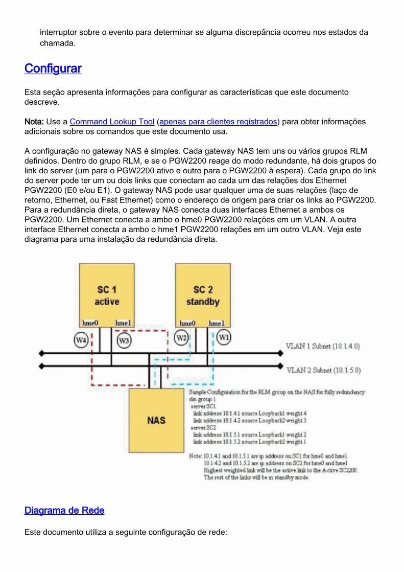
A configuração no gateway NAS é simples. Cada gateway NAS tem uns ou vários grupos RLMdefinidos. Dentro do grupo RLM, e se o PGW2200 reage do modo redundante, há dois grupos dolink do server (um para o PGW2200 ativo e outro para o PGW2200 à espera). Cada grupo do linkdo server pode ter um ou dois links que conectam ao cada um das relações dos EthernetPGW2200 (E0 e/ou E1). O gateway NAS pode usar qualquer uma de suas relações (laço deretorno, Ethernet, ou Fast Ethernet) como o endereço de origem para criar os links ao PGW2200.Para a redundância direta, o gateway NAS conecta duas interfaces Ethernet a ambos osPGW2200. Um Ethernet conecta a ambo o hme0 PGW2200 relações em um VLAN. A outrainterface Ethernet conecta a ambo o hme1 PGW2200 relações em um outro VLAN. Veja estediagrama para uma instalação da redundância direta.
Diagrama de Rede
Este documento utiliza a seguinte configuração de rede:

Configurações
Para instruções passo a passo em como estabelecer o grupo RLM para falar com ao PGW2200,refira configurar o Gateways de mídia para a interconexão SS7 para a solução e o RedundantLink Manager (RLM) do Gateways de voz.
Este documento não cobre as instruções passo a passo em como provision o PGW2200 para ainterconexão SS7. Refira estes à documentação para mais informação detalhada:
Documentação da liberação 7 do controlador do gateway do Cisco media●
Interconexão do Cisco SS7 para a solução do Gateways de voz, liberação 1.1●
A instalação & manual de configuração da liberação de software Cisco MGC 7●
Guia do abastecimento da liberação 7 de Cisco MGC●
Em lugar de, este documento concentra-se na área relativa ao NAS setup e à verificação eTroubleshooting da perspectiva PGW2200.
Esta é uma configuração de exemplo setup para o gateway NAS. Note que nossa instalação delaboratório não é inteiramente redundante. O gateway NAS tem somente um circuito desinalização definido a cada um dos PGW2200.
PGW2200 no NAS
isdn switch-type primary-ni !--- Define the switch-type
to use. !--- For SS7, this must be primary-ni. !
controller T1 0 framing esf clock source line primary
linecode b8zs pri-group timeslots 1-24 nfas_d primary
nfas_int 0 nfas_group 0 !--- Configure the NFAS group 0.
! interface Serial0:23 no ip address encapsulation ppp
isdn switch-type primary-ni !--- Define the switch-type
to use. !--- For SS7, this must be primary-ni. isdn

incoming-voice modem isdn rlm-group 0 !--- Bind the RLM
group 0 to the D-channel. !--- This causes the ISDN
signaling to go over IP instead of the TDM D-channel. no
isdn send-status-enquiry !--- Timeslot24. isdn
negotiate-bchan resend-setup isdn bchan-number-order
ascending ! interface FastEthernet0 ip address
172.16.13.141 255.255.255.224 duplex auto speed auto !
rlm group 0 !--- Define the RLM group parameters to talk
with the PGW 2200. server sc1 !--- Specify the first PGW
2200 and IP addresses used to setup the link. link
address 172.16.13.132 source FastEthernet0 weight 2
server sc3 !--- Specify the first PGW 2200 and IP
addresses used to setup the link. LINK ADDRESS
172.16.13.134 SOURCE FASTETHERNET0 WEIGHT 1 !
Verificar
Esta seção fornece informações que você pode usar para confirmar se sua configuração funcionaadequadamente.
A Output Interpreter Tool (somente clientes registrados) oferece suporte a determinadoscomandos show, o que permite exibir uma análise da saída do comando show.
mostre o grupo do rlm — Verifica que o grupo RLM é em serviço no gateway NAS.●
status de ISDN da mostra — Verifica que a sinalização ISDN trabalha corretamente nogateway NAS.
●
mostre o T1 do controlador — Verifica que todo o controlador T1/E1 é em serviço limpa nogateway NAS.
●
mostre o serviço isdn — Verifica que todos os canais do portador estão no serviço nogateway NAS.
●
RTRV-NE — Verifica que o PGW2200 é ascendente e ativo.●
RTRV-softw: todos — Verifica que todos os processos de software são executado noPGW2200.
●
RTRV-SC: todos — Verifica que todos os circuitos de sinalização estão no serviço noPGW2200.
●
RTRV-dest: todos — Verifica que todos os links do destino estão no serviço no PGW2200.●
RTRV-tc: todos — Verifica que todos os CIC são ascendentes e inativos das perspectivasSS7 e de gateway NAS.
●
Verifique para ver se há estes artigos no gateway NAS:
Certifique-se de que o grupo RLM é ascendente e é executado usando o comando show rlmgroup.
●
Certifique-se dos trabalhos da sinalização ISDN que usam corretamente o comando showisdn status.
●
Certifique-se que todo o controlador T1/E1 seja em serviço limpam usando o comando showcontroller t1.
●
Certifique-se que todos os canais do portador estão no serviço usando o comando show isdnservice.
●
Verifique para ver se há estes artigos no PGW2200:
Certifique-se que o sistema é ascendente e active usando o comando mml RTRV-NE.●

Certifique-se que todos os processos de software estão sendo executado usando o RTRV-softw: todo o comando mml.
●
Certifique-se que todos os circuitos de sinalização estão no serviço usando o RTRV-SC: todoo comando mml.
●
Certifique-se que todos os links do destino estão no serviço usando o RTRV-dest: todo ocomando mml.
●
Certifique-se que todos os CIC são ascendentes e INATIVOS do SS7 e da perspectiva dogateway NAS usando o RTRV-tc: todo o comando mml.
●
Este é exemplo de saída de comando do gateway NAS que se comunica com o PGW2200 semerros.
NAS1#show rlm group 0 RLM Group 0 Status User/Port: RLM_MGR/3000 ISDN/3001 !--- UDP port used to
communicate to the PGW 2200. RLM Version : 2 Link State: Up Last Link Status Reported: Up !---
RLM is up and running. Next tx TID: 1 Last rx TID: 0 Server Link Group[sc1]: Last Reported
Priority: HIGH link [172.16.13.141(FastEthernet0), 172.16.13.132] = socket[active] !--- Link to
the active PGW 2200. Server Link Group[sc3]: Last Reported Priority: LOW link
[172.16.13.141(FastEthernet0), 172.16.13.134] = socket[standby] !--- Link to the standby PGW
2200. RLM Group 0 Timer Values open_wait = 3s force-down = 30s recovery = 12s switch-link = 5s
minimum-up = 60s retransmit = 1s keepalive = 1s !--- Timer for the echo sent and received. RLM
Group 0 Statistics Link_up: last time occurred at *Jan 14 10:27:23.531, total transition=1
avg=00:00:00.000, max=00:00:00.000, min=00:00:00.000, latest=00:00:00.000 Link_down: last time
occurred at *Jan 14 10:26:47.531, total transition=1 avg=00:00:36.000, max=00:00:36.000,
min=00:00:00.000, latest=00:00:36.000 Link_recovered: last time occurred at none, success=0(0%),
failure=0 avg=0.000s, max=0.000s, min=0.000s, latest=0.000s Link_switched: last time occurred at
none, success=0(0%), failure=0 avg=0.000s, max=0.000s, min=0.000s, latest=0.000s Server_changed:
last time occurred at none for totally 0 times Server Link Group[sc1]: Open the link
[172.16.13.141(FastEthernet0), 172.16.13.132]: last time occurred at *Jan 14 10:27:17.531,
success=1(100%), failure=0 avg=3.000s, max=3.000s, min=0.000s, latest=3.000s Echo over link
[172.16.13.141(FastEthernet0), 172.16.13.132]: last time occurred at *Jan 14 10:30:51.531,
success=204(99%), failure=1 avg=0.000s, max=0.004s, min=0.000s, latest=0.000s Server Link
Group[sc3]: Open the link [172.16.13.141(FastEthernet0), 172.16.13.134]: last time occurred at
*Jan 14 10:27:17.531, success=1(100%), failure=0 avg=3.000s, max=3.000s, min=0.000s,
latest=3.000s Echo over link [172.16.13.141(FastEthernet0), 172.16.13.134]: last time occurred
at *Jan 14 10:30:51.531, success=212(99%), failure=1 avg=0.000s, max=0.000s, min=0.000s,
latest=0.000s
Esta lista fornece as explicações para os temporizadores RLM.
open_wait = 3s — A espera para que o pedido de conexão seja enviada e recebida sem erros.●
de força desativado = 30s — A hora mínima de forçar o RLM a ficar no estado inativo paracertificar-se da extremidade remota detecta que o estado do link está para baixo.
●
recuperação = 12s — O momento de permitir que o link recupere ao link de backup antes quevocê declarar o link para baixo.
●
interruptor-link = 5s — O momento de detectar a falha no switch do link.●
mínimo até = 60s — O momento mínimo de estabilizar o link recentemente recuperado dapreferência maior antes de comutar sobre.
●
retransmita = 1s — O temporizador de nova transmissão de UDP para cada mensagemrequest RLM antes do pedido é enviada e recebida sem erros.
●
keepalive = 1s — Temporizador para o eco enviado e recebido.●
NAS1#show isdn stat Global ISDN Switchtype = primary-ni ISDN Serial0:23 interface rlm-group = 0
!--- D-channel bind to rlm-group 0. dsl 0, interface ISDN Switchtype = primary-ni : Primary D-
channel of nfas group 0 Layer 1 Status: ACTIVE Layer 2 Status: TEI = 0, Ces = 1, SAPI = 0, State
= MULTIPLE_FRAME_ESTABLISHED !--- Good. Layer 3 Status: 0 Active Layer 3 Call(s) Active dsl 0
CCBs = 0 The Free Channel Mask: 0x80FFFFFF Total Allocated ISDN CCBs = 0 NAS1#show isdn service
PRI Channel Statistics: ISDN Se0:23 SC, Channel [1-24] !--- Note the keyword PGW 2200. In normal
ISDN, it is not there. Configured Isdn Interface (dsl) 0 Channel State (0=Idle 1=Proposed 2=Busy

3=Reserved 4=Restart 5=Maint_Pend) Channel : 1 2 3 4 5 6 7 8 9 0 1 2 3 4 5 6 7 8 9 0 1 2 3 4
State : 0 0 0 0 0 0 0 0 0 0 0 0 0 0 0 0 0 0 0 0 0 0 0 0 !--- All timeslots are good and idle
including timeslot 24. Service State (0=Inservice 1=Maint 2=Outofservice) Channel : 1 2 3 4 5 6
7 8 9 0 1 2 3 4 5 6 7 8 9 0 1 2 3 4 State : 0 0 0 0 0 0 0 0 0 0 0 0 0 0 0 0 0 0 0 0 0 0 0 0
NAS1# NAS1#show controller t1 T1 0 is up. !--- T1 is up and running clean with no errors.
Applique type is Channelized T1 Cablelength is short 133 No alarms detected. alarm-trigger is
not set Version info of slot 0: HW: 4, PLD Rev: 0 Manufacture Cookie Info: EEPROM Type 0x0001,
EEPROM Version 0x01, Board ID 0x42, Board Hardware Version 1.32, Item Number 73-2217-05, Board
Revision B16, Serial Number 10077744, PLD/ISP Version 0.0, Manufacture Date 25-Sep-1998. Framing
is ESF, Line Code is B8ZS, Clock Source is Line Primary. !--- T1 physical layer configuration.
Data in current interval (429 seconds elapsed): 0 Line Code Violations, 0 Path Code Violations 0
Slip Secs, 0 Fr Loss Secs, 0 Line Err Secs, 0 Degraded Mins 0 Errored Secs, 0 Bursty Err Secs, 0
Severely Err Secs, 0 Unavail Secs Total Data (last 3 15 minute intervals): 0 Line Code
Violations, 0 Path Code Violations, 0 Slip Secs, 0 Fr Loss Secs, 0 Line Err Secs, 0 Degraded
Mins, 0 Errored Secs, 0 Bursty Err Secs, 0 Severely Err Secs, 0 Unavail Secs
Este é exemplo de saída de comando do PGW2200. Detalha artigos para verificar para ver se hádurante a verificação.
sc1 mml>rtrv-ne MGC-01 - Media Gateway Controller 2002-01-14 11:47:24 M RTRV "Type:MGC"
"Hardware platform:sun4u sparc SUNW,Ultra-60" "Vendor:"Cisco Systems, Inc."" "Location:MGC-01 -
Media Gateway Controller" "Version:"7.4(11)" !--- MGC software version running on PGW 2200.
"Platform State:ACTIVE" !--- State of the PGW 2200. ; sc1 mml>rtrv-softw:all !--- Make sure all
the processes are active and running. MGC-01 - Media Gateway Controller 2002-01-14 11:47:29 M
RTRV "CFM-01:RUNNING ACTIVE" "ALM-01:RUNNING ACTIVE" "MM-01:RUNNING ACTIVE" "AMDMPR-01:RUNNING
ACTIVE" "CDRDMPR-01:RUNNING ACTIVE" "DSKM-01:RUNNING IN N/A STATE" "MMDB-01:RUNNING IN N/A
STATE" "POM-01:RUNNING ACTIVE" "MEASAGT:RUNNING ACTIVE" "OPERSAGT:RUNNING ACTIVE"
"PROVSAGT:RUNNING ACTIVE" "priip-1:RUNNING IN N/A STATE" "Replic-01:RUNNING ACTIVE" "ENG-
01:RUNNING ACTIVE" "IOCM-01:RUNNING ACTIVE" "TCAP-01:RUNNING IN N/A STATE" "ss7-a-1:RUNNING IN
N/A STATE" "FOD-01:RUNNING IN N/A STATE" "LOG-01:RUNNING IN N/A STATE" ; sc1 mml>rtrv-sc:all
MGC-01 - Media Gateway Controller 2002-01-14 11:47:36 M RTRV "gw1link1:signas1,LID=0:IS" !--- IP
signaling link from the NAS to PGW 2200 (rlm group) !--- LID=0:IS means the RLM is up. null
"ls1-link1:ls1,LID=0:IS" !--- IP signaling link from the SLT to the PGW 2200 (C7IPLINK). null ;
sc1 mml>rtrv-dest:all MGC-01 - Media Gateway Controller 2002-01-14 11:47:39 M RTRV "dpc-
sc2200:PKG=SS7-ANSI,ASSOC=signas1,PST=IS,SST=RSTO" !--- SS7 signal to the destination point code
(DPC). "signas1:PKG=ISDNPRI,ASSOC=dpc-sc2200,PST=IS,SST=RSTO" !--- ISDN signaling between the
NAS and the PGW 2200 !--- (same as show isdn status on NAS). ; sc1 mml>rtrv-tc:all Retrieving
results. This could take a few moments... MGC-01 - Media Gateway Controller 2002-01-14 11:47:46
M RTRV "dpc-sc2200:CIC=1,PST=IS,CALL=IDLE,BLK=NONE" !--- InterMachine Trunk (IMT) status on SS7
side toward the DPC switch. "dpc-sc2200:CIC=2,PST=IS,CALL=IDLE,BLK=NONE" "dpc-
sc2200:CIC=3,PST=IS,CALL=IDLE,BLK=NONE" "dpc-sc2200:CIC=4,PST=IS,CALL=IDLE,BLK=NONE" "dpc-
sc2200:CIC=5,PST=IS,CALL=IDLE,BLK=NONE" "dpc-sc2200:CIC=6,PST=IS,CALL=IDLE,BLK=NONE" "dpc-
sc2200:CIC=7,PST=IS,CALL=IDLE,BLK=NONE" "dpc-sc2200:CIC=8,PST=IS,CALL=IDLE,BLK=NONE" "dpc-
sc2200:CIC=9,PST=IS,CALL=IDLE,BLK=NONE" "dpc-sc2200:CIC=10,PST=IS,CALL=IDLE,BLK=NONE" "dpc-
sc2200:CIC=11,PST=IS,CALL=IDLE,BLK=NONE" "dpc-sc2200:CIC=12,PST=IS,CALL=IDLE,BLK=NONE" "dpc-
sc2200:CIC=13,PST=IS,CALL=IDLE,BLK=NONE" "dpc-sc2200:CIC=14,PST=IS,CALL=IDLE,BLK=NONE" "dpc-
sc2200:CIC=15,PST=IS,CALL=IDLE,BLK=NONE" "dpc-sc2200:CIC=16,PST=IS,CALL=IDLE,BLK=NONE" "dpc-
sc2200:CIC=17,PST=IS,CALL=IDLE,BLK=NONE" "dpc-sc2200:CIC=18,PST=IS,CALL=IDLE,BLK=NONE" <Press
Enter to continue OR Press * and Enter to quit output of command> "dpc-
sc2200:CIC=19,PST=IS,CALL=IDLE,BLK=NONE" "dpc-sc2200:CIC=20,PST=IS,CALL=IDLE,BLK=NONE" "dpc-
sc2200:CIC=21,PST=IS,CALL=IDLE,BLK=NONE" "dpc-sc2200:CIC=22,PST=IS,CALL=IDLE,BLK=NONE" "dpc-
sc2200:CIC=23,PST=IS,CALL=IDLE,BLK=NONE" "dpc-sc2200:CIC=24,PST=IS,CALL=IDLE,BLK=NONE"
"signas1:TC=1,CALL=IDLE,PST=IS,SPAN=0" !--- Corresponding T1 timeslots on the NAS gateway side
to the SC !--- (same as show isdn service on NAS) CALL= specify the direction of the call !---
SPAN=0 specify the nfas_int. "signas1:TC=2,CALL=IDLE,PST=IS,SPAN=0"
"signas1:TC=3,CALL=IDLE,PST=IS,SPAN=0" "signas1:TC=4,CALL=IDLE,PST=IS,SPAN=0"
"signas1:TC=5,CALL=IDLE,PST=IS,SPAN=0" "signas1:TC=6,CALL=IDLE,PST=IS,SPAN=0"
"signas1:TC=7,CALL=IDLE,PST=IS,SPAN=0" "signas1:TC=8,CALL=IDLE,PST=IS,SPAN=0"
"signas1:TC=9,CALL=IDLE,PST=IS,SPAN=0" "signas1:TC=10,CALL=IDLE,PST=IS,SPAN=0"
"signas1:TC=11,CALL=IDLE,PST=IS,SPAN=0" "signas1:TC=12,CALL=IDLE,PST=IS,SPAN=0"
"signas1:TC=13,CALL=IDLE,PST=IS,SPAN=0" "signas1:TC=14,CALL=IDLE,PST=IS,SPAN=0" <Press Enter to
continue OR Press * and Enter to quit output of command> "signas1:TC=15,CALL=IDLE,PST=IS,SPAN=0"
"signas1:TC=16,CALL=IDLE,PST=IS,SPAN=0" "signas1:TC=17,CALL=IDLE,PST=IS,SPAN=0"
"signas1:TC=18,CALL=IDLE,PST=IS,SPAN=0" "signas1:TC=19,CALL=IDLE,PST=IS,SPAN=0"

"signas1:TC=20,CALL=IDLE,PST=IS,SPAN=0" "signas1:TC=21,CALL=IDLE,PST=IS,SPAN=0"
"signas1:TC=22,CALL=IDLE,PST=IS,SPAN=0" "signas1:TC=23,CALL=IDLE,PST=IS,SPAN=0"
"signas1:TC=24,CALL=IDLE,PST=IS,SPAN=0" sc1 mml>prov-rtrv:all !--- Retrieved the current
configuration on the PGW 2200. MGC-01 - Media Gateway Controller 2002-01-15 09:25:12 M RTRV
"session=active:all" ; sc1 mml>prov-rtrv:NASPATH:name="signas1" MGC-01 - Media Gateway
Controller 2002-01-15 09:25:27 M RTRV "SESSION=ACTIVE:NASPATH" ; !--- In PGW release 9.3(2) and
later, the BELL_1268_C3 variant !--- is changed to BELL_1268_C2. prov-
add:NASPATH:NAME="signas1",DESC="Signaling Service to V5300-1",EXTNODE="v5300-
1",MDO="BELL_1268_C2",CUSTGRPID="0000" sc1 mml>prov-rtrv:IPLNK:name="gw1link1" !--- Get detail
information on the IP link to the PGW 2200. MGC-01 - Media Gateway Controller 2002-01-15
09:25:49 M RTRV "SESSION=ACTIVE:IPLNK" ; sc1 mml>
Você pode igualmente verificar esta mesma informação nos arquivos do .DAT situados nodiretório de /opt/CiscoMGC/etc. Os arquivos do .DAT são a informação recolhida de configurar eabastecimento o PGW2200. O arquivo do sigChanDevIp.dat contém toda a informação no enlaceIP ao PGW2200 do gateway NAS e do SLT.
sc1% more sigChanDevIp.dat00100001 IP_Addr1 3001 172.16.13.141 3001
0.0.0.0 255.255.255.255001d0001 IP_Addr1 7000 172.16.13.139 32767
0.0.0.0 255.255.255.255
sc1%
Use esta informação para certificar-se de que os endereços IP de Um ou Mais Servidores CiscoICM NT configurados no sigChanDevIp.dat estão corretos.
00100001 IP_Addr1 3001 172.16.13.141 3001 0.0.0.0 255.255.255.255
00100001 = Signalling Channel Component ID as defined for the engine.
!--- Must match what is configured in the components.dat file. IP_Addr1 = Symbolic link to the
name defined within XECfgParm.dat !--- *.IP_Addr1 = 172.16.13.132 # Address of interface on
motherboard. 3001 = UDP port defined for receive side of ISDN messages. !--- RLM manager runs on
the - 1 value, or 3000 in this example. 172.16.13.141 = IP address of the NAS gateway. !--- Must
match the IP address defined in the RLM group on the NAS gateway. 3001 = UDP port defined for
transmit side of ISDN messages for the NAS gateway !--- RLM manager runs on the - 1 value, or
3000 in this example.
Certifique-se de que o protocolo ISDN correto está configurado para ser executado na conexãoISDN/IP.
Obtenha as 00100001) informações do ID do componente PGW2200 (dentro do arquivo dosigChanDevIp.dat para o enlace IP. Então, vá ao arquivo sigChanDev.dat e obtenha o ID docomponente para o ID do componente do trajeto do sinal (00140001) na quarta coluna. Com esteID do componente do trajeto do sinal, use o arquivo sigPath.dat para encontrar o protocolo ISDNusado (BELL_1268_C3 ISDNPRI).
Nota: No PGW libere 9.3(2) e mais atrasado, a variação do BELL_1268_C3 é mudada aBELL_1268_C2.
Esta é a saída do PGW2200.
sc1% more sigChanDevIp.dat 00100001 IP_Addr1 3001 172.16.13.141 3001 0.0.0.0 255.255.255.255
001d0001 IP_Addr1 7000 172.16.13.139 32767 0.0.0.0 255.255.255.255 sc1% grep 00100001 *
components.dat:00100001 00140001 "gw1link1" "Link1 between gw1 and the sc2200-1"
sigChanDev.dat:00100001 00160001 1 00140001 0003000c 00060001 0 sigChanDevIp.dat:00100001
IP_Addr1 3001 172.16.13.141 3001 0.0.0.0 255.255.255.255 sc1% sc1% grep 00140001 *
bearChan.dat:101 00130002 ffff 1 00140001 0 1 bearChan.dat:102 00130002 ffff 2 00140001 0 2
bearChan.dat:103 00130002 ffff 3 00140001 0 3 bearChan.dat:104 00130002 ffff 4 00140001 0 4
bearChan.dat:105 00130002 ffff 5 00140001 0 5 bearChan.dat:106 00130002 ffff 6 00140001 0 6
bearChan.dat:107 00130002 ffff 7 00140001 0 7 bearChan.dat:108 00130002 ffff 8 00140001 0 8
bearChan.dat:109 00130002 ffff 9 00140001 0 9 bearChan.dat:110 00130002 ffff a 00140001 0 a
bearChan.dat:111 00130002 ffff b 00140001 0 b bearChan.dat:112 00130002 ffff c 00140001 0 c
bearChan.dat:113 00130002 ffff d 00140001 0 d bearChan.dat:114 00130002 ffff e 00140001 0 e
bearChan.dat:115 00130002 ffff f 00140001 0 f bearChan.dat:116 00130002 ffff 10 00140001 0 10

bearChan.dat:117 00130002 ffff 11 00140001 0 11 bearChan.dat:118 00130002 ffff 12 00140001 0 12
bearChan.dat:119 00130002 ffff 13 00140001 0 13 bearChan.dat:120 00130002 ffff 14 00140001 0 14
bearChan.dat:121 00130002 ffff 15 00140001 0 15 bearChan.dat:122 00130002 ffff 16 00140001 0 16
bearChan.dat:123 00130002 ffff 17 00140001 0 17 bearChan.dat:124 00130002 ffff 18 00140001 0 18
components.dat:00100001 00140001 "gw1link1" "Link1 between gw1 and the sc2200-1"
components.dat:00140001 00160001 "signas1" "Signaling service to gw1" sigChanDev.dat:00100001
00160001 1 00140001 0003000c 00060001 0 sigPath.dat:00140001 ISDNPRI BELL_1268_C3 0000 0101 22
network n 0 0 0 2 0000 N sc1%
Notas:
00140001 — ID do componente do trajeto do sinal.●
ISDNPRI — Valor para que o ISDN sobre o IP a trabalhar.●
BELL_1268_C3 0 — Especifica o tipo de protocolo NI2 preliminar (deve ser este valor para oISDN sobre o IP).
●
Nota: No PGW libere 9.3(2) e mais atrasado, a variação do BELL_1268_C3 é mudada aBELL_1268_C2.
Refira a referência de arquivo de dados de configuração para obter mais informações sobre docomponente e dos arquivos do .DAT.
Esta é alguma informação de referência para o PGW2200 à espera. A maioria desta informaçãoreage do modo standby (OOS) fora de serviço.
sc3 mml>rtrv-ne MGC-02 - Media Gateway Controller 2002-01-15 17:42:50 M RTRV "Type:MGC"
"Hardware platform:sun4u sparc SUNW,Ultra-60" "Vendor:"Cisco Systems, Inc."" "Location:MGC-02 -
Media Gateway Controller" "Version:"7.4(11)"" "Platform State:STANDBY" !--- The current state of
the PGW 2200. ; sc3 mml>rtrv-softw:all !--- Note the processes are running in STANDBY mode. MGC-
02 - Media Gateway Controller 2002-01-15 17:42:54 M RTRV "CFM-01:RUNNING STANDBY" "ALM-
01:RUNNING STANDBY" "MM-01:RUNNING STANDBY" "AMDMPR-01:RUNNING STANDBY" "CDRDMPR-01:RUNNING
STANDBY" "DSKM-01:RUNNING IN N/A STATE" "MMDB-01:RUNNING IN N/A STATE" "POM-01:RUNNING STANDBY"
"MEASAGT:RUNNING STANDBY" "OPERSAGT:RUNNING STANDBY" "PROVSAGT:RUNNING STANDBY" "priip-1:RUNNING
IN N/A STATE" "Replic-01:RUNNING STANDBY" "ENG-01:RUNNING STANDBY" "IOCM-01:RUNNING STANDBY"
"TCAP-01:RUNNING IN N/A STATE" "ss7-a-1:RUNNING IN N/A STATE" "FOD-01:RUNNING IN N/A STATE"
<Press Enter to continue OR Press * and Enter to quit output of command> "LOG-01:RUNNING IN N/A
STATE" ; sc3 mml> rtrv-sc:all MGC-02 - Media Gateway Controller 2002-01-15 17:43:00 M RTRV
"GW1LINK1:SIGNAS1,LID=0:OOS,STBY" "ls1-link1:ls1,LID=0:OOS,STBY" ; sc3 mml> rtrv-dest:all MGC-
02 - Media Gateway Controller 2002-01-15 17:43:04 M RTRV "dpc-sc2200:PKG=SS7-
ANSI,ASSOC=signas1,PST=IS,SST=RSTO" "SIGNAS1:PKG=ISDNPRI,ASSOC=DPC-SC2200,PST=IS,SST=RSTO" ;
Troubleshooting
Esta seção fornece informações que podem ser usadas para o troubleshooting da suaconfiguração.
Comandos para Troubleshooting
A Output Interpreter Tool (somente clientes registrados) oferece suporte a determinadoscomandos show, o que permite exibir uma análise da saída do comando show.
Nota: Consulte Informações Importantes sobre Comandos de Debugação antes de usarcomandos debug.
debugar o grupo do rlm x — Informação dos indicadores no keepalive e fluxo de pacote deinformação entre o PGW2200 e o gateway NAS.
●
mostre a lista de acesso 199 — Usado para filtrar no tráfego entre o PGW2200 e o NAS.●

debugar o detalhe do pacote 199 IP — Indica a informação sobre debugging IP detalhado.●
debugar isdn q921 — Indica os procedimentos de acesso da camada de link de dados 2 queocorrem no roteador no canal D da interface.
●
a mostra debuga — Os indicadores debugam a informação.●
status de ISDN da mostra — Indica o estado de todas as interfaces.●
mostre o grupo 0 do rlm — Indica o estado do RLM.●
Quando você pesquisa defeitos a comunicação entre o NAS e o PGW2200, há duas porçõesprincipais:
Sinalização RLM●
Sinalização ISDN●
Diversos problemas que podem fazer com que o RLM esteja no estado inativo são:
Configuração incorreta no roteador ou no PGW2200.●
Fisicamente, as relações (Ethernet, Fast Ethernet, x:23 de série) são parada programada outêm um cabo ruim.
●
Listas de acesso que obstruem uma comunicação entre o endereço IP de Um ou MaisServidores Cisco ICM NT de dois dispositivos, a porta 3000 (RLM-mgr), e 3001 UDP (ISDN).
●
No gateway NAS, execute o comando debug rlm group x olhar o keepalive e o fluxo de pacote deinformação entre o PGW2200 e o gateway NAS.
Esta saída mostra algum exemplo de saída de comando do gateway NAS. Na operação normal,há manutenções de atividade constante (ECHO_REQ e ECHO_ACK) trocadas entre o gatewayNAS e o PGW2200 cada 1 segundo. Se isto não ocorre, figure para fora quem é de resposta oude emissão o Keepalives.
Nota: O TID (ID de transação) é o mesmo reconhecimento da requisição de eco e do eco. Mesmoque o outro PGW2200 (172.16.13.134) reaja do modo standby, comunica-se constantemente como gateway NAS.
NAS1#debug rlm group 0 RLM Group debugging is on NAS1#terminal monitor NAS1# *Jan 14
14:50:53.270: rlm 0: link [172.16.13.141(FastEthernet0), 172.16.13.132] tx ECHO_REQ(tid=15304)
*Jan 14 14:50:53.270: rlm 0: link [172.16.13.141(FastEthernet0), 172.16.13.134] tx
ECHO_REQ(tid=15734) *Jan 14 14:50:53.270: rlm 0: link [172.16.13.141(FastEthernet0),
172.16.13.132] rx ECHO_ACK(tid=15304) *Jan 14 14:50:53.270: rlm 0: link
[172.16.13.141(FastEthernet0), 172.16.13.134] rx ECHO_ACK(tid=15734) *Jan 14 14:50:54.270: rlm
0: link [172.16.13.141(FastEthernet0), 172.16.13.132] tx ECHO_REQ(tid=15305) *Jan 14
14:50:54.270: rlm 0: link [172.16.13.141(FastEthernet0), 172.16.13.134] tx ECHO_REQ(tid=15735)
*Jan 14 14:50:54.270: rlm 0: link [172.16.13.141(FastEthernet0), 172.16.13.132] rx
ECHO_ACK(tid=15305) *Jan 14 14:50:54.270: rlm 0: link [172.16.13.141(FastEthernet0),
172.16.13.134] rx ECHO_ACK(tid=15735)
Esta é a partida do grupo RLM e sinalização ISDN quando você emite o comando no shut aogrupo RLM.
NAS1#show access-list 199 !--- Access-list used to filter on traffic between !--- the PGW 2200
and the NAS. Extended IP access list 199 permit ip host 172.16.13.132 host 172.16.13.141 permit
ip host 172.16.13.141 host 172.16.13.132 NAS1#debug ip packet 199 det IP packet debugging is on
(detailed) for access list 199 NAS1#debug rlm group 0 RLM Group debugging is on NAS1#debug isdn
q921 ISDN Q921 packets debugging is on NAS1#debug rlm group 0 event RLM Group Event debugging is
on NAS1#debug rlm group 0 packet RLM Group Packet debugging is on NAS1#show debug Generic IP: IP
packet debugging is on (detailed) for access list 199 RLM_GROUP: RLM Group debugging is on RLM
Group Event debugging is on RLM Group Packet debugging is on ISDN: ISDN Q921 packets debugging
is on ISDN Q921 packets debug DSLs. (On/Off/No DSL:1/0/-) DSL 0 --> 7 1 - - - - - - - NAS1#
NAS1#configure term Enter configuration commands, one per line. End with CNTL/Z.
NAS1(config)#rlm group NAS1(config)#rlm group 0 NAS1(config-rlm-group)#no shut NAS1(config-rlm-

group)#end NAS1# !--- Receive event to enable RLM and wait for the force-down timer !--- to
expire before it starts to send the keepalives to !--- establish the link to the PGW 2200. *Jan
14 18:04:21.734: rlm 0: [State_Shutdown, rx ENABLE] *Jan 14 18:04:22.222: %SYS-5-CONFIG_I:
Configured from console by vty0 (171.69.85.65) NAS1#show rlm group 0 RLM Group 0 Status
User/Port: RLM_MGR/3000 ISDN/3001 RLM Version : 2 Link State: Down Last Link Status Reported:
Down !--- Current state of the RLM group. Next tx TID: 1 Last rx TID: 0 Server Link Group[sc1]:
Last Reported Priority: HIGH link [172.16.13.141(FastEthernet0), 172.16.13.132] = socket[closed]
!--- Communication socket is closed. Server Link Group[sc3]: Last Reported Priority: LOW link
[172.16.13.141(FastEthernet0), 172.16.13.134] = socket[closed] RLM Group 0 Timer Values
open_wait = 3s force-down = 30s recovery = 12s switch-link = 5s minimum-up = 60s retransmit = 1s
keepalive = 1s RLM Group 0 Statistics Link_up: last time occurred at *Jan 14 17:59:49.870, total
transition=4 avg=01:49:34.264, max=05:40:16.976, min=00:00:00.000, latest=00:02:08.728
Link_down: last time occurred at *Jan 14 18:01:58.598, total transition=3 avg=00:08:27.002,
max=00:16:18.004, min=00:00:00.000, latest=00:16:18.004 Link_recovered: last time occurred at
*Jan 14 12:03:14.887, success=2(100%), failure=0 avg=0.004s, max=0.004s, min=0.000s,
latest=0.004s Link_switched: last time occurred at none, success=0(0%), failure=0 avg=0.000s,
max=0.000s, min=0.000s, latest=0.000s Server_changed: last time occurred at *Jan 14 12:03:14.891
for totally 2 times Server Link Group[sc1]: Open the link [172.16.13.141(FastEthernet0),
172.16.13.132]: last time occurred at *Jan 14 17:59:46.870, success=2(100%), failure=0
avg=1.502s, max=3.000s, min=0.000s, latest=0.004s Echo over link [172.16.13.141(FastEthernet0),
172.16.13.132]: last time occurred at *Jan 14 18:01:57.874, success=25581(99%), failure=35
avg=0.000s, max=0.032s, min=0.000s, latest=0.000s Server Link Group[sc3]: Open the link
[172.16.13.141(FastEthernet0), 172.16.13.134]: last time occurred at *Jan 14 17:59:46.870,
success=2(100%), failure=0 avg=1.502s, max=3.000s, min=0.000s, latest=0.004s Echo over link
[172.16.13.141(FastEthernet0), 172.16.13.134]: last time occurred at *Jan 14 18:01:57.874,
success=26182(99%), failure=40 avg=0.000s, max=0.032s, min=0.000s, latest=0.000s NAS1#show isdn
status !--- ISDN status is always DOWN if RLM is not up and running. Global ISDN Switchtype =
primary-ni ISDN Serial0:23 interface rlm-group = 0 dsl 0, interface ISDN Switchtype = primary-ni
: Primary D-channel of nfas group 0 Layer 1 Status: DEACTIVATED Layer 2 Status: TEI = 0, Ces =
1, SAPI = 0, State = TEI_ASSIGNED Layer 3 Status: 0 Active Layer 3 Call(s) Active dsl 0 CCBs = 0
The Free Channel Mask: 0xFFFFFF Total Allocated ISDN CCBs = 0 NAS1# !--- Force-down timer
expired and router starts to send out !--- the ECHO_REQ to the PGW 2200 to establish the link.
*Jan 14 18:04:51.734: rlm 0: [State_Down, rx DOWN_MIN_TIMEOUT] *Jan 14 18:04:51.734: rlm 0: link
[172.16.13.141(FastEthernet0), 172.16.13.132] = socket[172.16.13.141, 172.16.13.132] !--- Open
the RLM user socket for both the RLM !--- manager and ISDN signaling. !--- Router sends out
ECHO_REQ (RLM keepalive) to !--- the PGW 2200 to start the communication. *Jan 14 18:04:51.734:
rlm 0: [State_Down, rx USER_SOCKET_OPENED] over link [172.16.13.141(FastEthernet0),
172.16.13.132] for user RLM_MGR *Jan 14 18:04:51.734: rlm 0: link [172.16.13.141(FastEthernet0),
172.16.13.132] is opened *Jan 14 18:04:51.734: rlm 0: link [172.16.13.141(FastEthernet0),
172.16.13.132] tx ECHO_REQ(tid=25616) *Jan 14 18:04:51.734: IP: s=172.16.13.141 (local),
d=172.16.13.132 (FastEthernet0), len 36, sending *Jan 14 18:04:51.734: UDP src=3000, dst=3000
*Jan 14 18:04:51.734: rlm 0: link [172.16.13.141(FastEthernet0), 172.16.13.132] =
socket[172.16.13.141, 172.16.13.132] *Jan 14 18:04:51.734: rlm 0: [State_Down, rx
USER_SOCKET_OPENED] over link [172.16.13.141(FastEthernet0), 172.16.13.132] for user ISDN !---
Same process for the standby PGW 2200. *Jan 14 18:04:51.734: rlm 0: link
[172.16.13.141(FastEthernet0), 172.16.13.134] = socket[172.16.13.141, 172.16.13.134] *Jan 14
18:04:51.734: rlm 0: [State_Down, rx USER_SOCKET_OPENED] over link
[172.16.13.141(FastEthernet0), 172.16.13.134] for user RLM_MGR *Jan 14 18:04:51.734: rlm 0: link
[172.16.13.141(FastEthernet0), 172.16.13.134] is opened *Jan 14 18:04:51.734: rlm 0: link
[172.16.13.141(FastEthernet0), 172.16.13.134] tx ECHO_REQ(tid=26222) *Jan 14 18:04:51.738: rlm
0: link [172.16.13.141(FastEthernet0), 172.16.13.134] = socket[172.16.13.141, 172.16.13.134]
*Jan 14 18:04:51.738: rlm 0: [State_Down, rx USER_SOCKET_OPENED] over link
[172.16.13.141(FastEthernet0), 172.16.13.134] for user ISDN *Jan 14 18:04:51.738: IP:
s=172.16.13.132 (FastEthernet0), d=172.16.13.141 (FastEthernet0), len 36, rcvd 3 *Jan 14
18:04:51.738: UDP src=3000, dst=3000 !--- Recevied the ECHO_ACK back from the active and !---
standby PGW 2200. *Jan 14 18:04:51.738: rlm 0: link [172.16.13.141(FastEthernet0),
172.16.13.132] rx ECHO_ACK(tid=25616) *Jan 14 18:04:51.738: rlm 0: [State_Down, rx LINK_OPENED]
over link [172.16.13.141(FastEthernet0), 172.16.13.132] *Jan 14 18:04:51.738: rlm 0: link
[172.16.13.141(FastEthernet0), 172.16.13.134] rx ECHO_ACK(tid=26222) *Jan 14 18:04:51.738: rlm
0: [State_Down, rx LINK_OPENED] over link [172.16.13.141(FastEthernet0), 172.16.13.134] !---
Router continues to send out ECHO_REQ and !--- receive ECHO_ACK several times. !--- This is
needed to make sure the communication !--- between the NAS gateway and PGW 2200 is good. *Jan 14
18:04:52.738: rlm 0: link [172.16.13.141(FastEthernet0), 172.16.13.132] tx ECHO_REQ(tid=25617)
*Jan 14 18:04:52.738: IP: s=172.16.13.141 (local), d=172.16.13.132 (FastEthernet0), len 36,

sending *Jan 14 18:04:52.738: UDP src=3000, dst=3000 *Jan 14 18:04:52.738: rlm 0: link
[172.16.13.141(FastEthernet0), 172.16.13.134] tx ECHO_REQ(tid=26223) *Jan 14 18:04:52.738: IP:
s=172.16.13.132 (FastEthernet0), d=172.16.13.141 (FastEthernet0), len 36, rcvd 3 *Jan 14
18:04:52.738: UDP src=3000, dst=3000 *Jan 14 18:04:52.738: rlm 0: link
[172.16.13.141(FastEthernet0), 172.16.13.132] rx ECHO_ACK(tid=25617) *Jan 14 18:04:52.738: rlm
0: link [172.16.13.141(FastEthernet0), 172.16.13.134] rx ECHO_ACK(tid=26223) *Jan 14
18:04:53.738: rlm 0: link [172.16.13.141(FastEthernet0), 172.16.13.132] tx ECHO_REQ(tid=25618)
*Jan 14 18:04:53.738: IP: s=172.16.13.141 (local), d=172.16.13.132 (FastEthernet0), len 36,
sending *Jan 14 18:04:53.738: UDP src=3000, dst=3000 *Jan 14 18:04:53.738: rlm 0: link
[172.16.13.141(FastEthernet0), 172.16.13.134] tx ECHO_REQ(tid=26224) *Jan 14 18:04:53.738: IP:
s=172.16.13.132 (FastEthernet0), d=172.16.13.141 (FastEthernet0), len 36, rcvd 3 *Jan 14
18:04:53.738: UDP src=3000, dst=3000 *Jan 14 18:04:53.738: rlm 0: link
[172.16.13.141(FastEthernet0), 172.16.13.132] rx ECHO_ACK(tid=25618) *Jan 14 18:04:53.738: rlm
0: link [172.16.13.141(FastEthernet0), 172.16.13.134] rx ECHO_ACK(tid=26224) !--- After three
keepalives are transmitted and three replies !--- are received back (approximately the open_wait
timer), the router !--- starts the link activation. !--- Note that all of the links have a
preferred weight !--- association. NAS chooses the link with the highest preference !--- among
those successful links. NAS waits for !--- a certain amount of time specified by open_wait timer
!--- (three seconds) to allow the highest preference connections to reach !--- the PGW 2200
before it selects the signaling link. !--- Once the highest preference link is established, !---
NAS chooses it as the active signaling link immediately and does not wait !--- for the rest of
the connections. Once the active signaling link is decided, !--- NAS sends out the datagram RLM
message START_REQ over the chosen !--- link to the PGW 2200. When PGW 2200 receives this
message, !--- SAS responds with a START_ACK message and then declares the !--- link to be up as
well. At this point, the PGW 2200 can start !--- to transmit packets. When NAS receives
START_ACK back, NAS !--- declares the link to be up or active and leaves the rest of the links
alone. !--- For managing UDP links, UDP sockets opened under an active !--- link are assigned to
those registered RLM users for !--- transmitting and receiving packets. The status RLM_LINK_UP
!--- is reported to RLM users after the signaling link is !--- established and synchronized. At
this point, NAS can start !--- to transmit packets. Due to the unreliable transport under UDP,
!--- these START_REQ and START_ACK packets can get lost. RLM uses !--- the timer retransmission
timer to wait for the START_ACK. !--- If the timer expires and the link is still not closed or
down, the packet !--- is resent under UDP. *Jan 14 18:04:54.734: rlm 0: [State_Down, rx
OPEN_WAIT_TIMEOUT] *Jan 14 18:04:54.734: rlm 0: link [172.16.13.141(FastEthernet0),
172.16.13.132] tx START_REQ(tid=0) *Jan 14 18:04:54.734: IP: s=172.16.13.141 (local),
d=172.16.13.132 (FastEthernet0), len 36, sending *Jan 14 18:04:54.734: UDP src=3000, dst=3000
*Jan 14 18:04:54.734: rlm 0: link [172.16.13.141(FastEthernet0), 172.16.13.132] requests
activation *Jan 14 18:04:54.734: IP: s=172.16.13.132 (FastEthernet0), d=172.16.13.141
(FastEthernet0), len 36, rcvd 3 *Jan 14 18:04:54.734: UDP src=3000, dst=3000 !--- RLM manager
UDP port. *Jan 14 18:04:54.734: IP: s=172.16.13.132 (FastEthernet0), d=172.16.13.141
(FastEthernet0), len 31, rcvd 3 *Jan 14 18:04:54.734: UDP src=3001, dst=3001 !--- ISDN signaling
UDP port. *Jan 14 18:04:54.734: rlm 0: link [172.16.13.141(FastEthernet0), 172.16.13.132] rx
START_ACK(tid=0) *Jan 14 18:04:54.734: rlm 0: [State_Down, rx START_ACK] over link
[172.16.13.141(FastEthernet0), 172.16.13.132] *Jan 14 18:04:54.734: %ISDN-4-RLM_STATUS_CHANGE:
ISDN SC Se0:23 SC: Status Changed to: Link Up. *Jan 14 18:04:54.734: rlm 0: link
[172.16.13.141(FastEthernet0), 172.16.13.132] is activated !--- The router starts to establish
the ISDN signaling !--- with the PGW 2200. Note, the NAS gateway sends the !--- signaling packet
across the FastEthernet interface using UDP !--- port 3001. Once both sides have received the !-
-- Unnumbered Acknowledge (UA) frame from each other, ISDN Layer 2 status !--- moves from the
TEI_ASSIGNED state to the MULTIPLE_FRAME_ESTABLISHED state. !--- Next, normal ISDN keepalives
(RRf and RRp) are being exchanged between !--- the PGW 2200 and the NAS gateway. *Jan 14
18:04:54.738: ISDN Se0:23 SC: RX <- SABMEp c/r = 1 sapi = 0 tei = 0 *Jan 14 18:04:54.738: %ISDN-
6-LAYER2UP: Layer 2 for Interface Se0:23 SC, TEI 0 changed to up *Jan 14 18:04:54.738: ISDN
Se0:23 SC: TX -> SABMEp c/r = 0 sapi = 0 tei = 0 *Jan 14 18:04:54.738: IP: s=172.16.13.141
(local), d=172.16.13.132 (FastEthernet0), len 31, sending *Jan 14 18:04:54.738: UDP src=3001,
dst=3001 *Jan 14 18:04:54.742: ISDN Se0:23 SC: TX -> UAf c/r = 1 sapi = 0 tei = 0 *Jan 14
18:04:54.742: IP: s=172.16.13.141 (local), d=172.16.13.132 (FastEthernet0), len 31, sending *Jan
14 18:04:54.742: UDP src=3001, dst=3001 *Jan 14 18:04:54.742: ISDN Se0:23 SC: TX -> INFOc sapi =
0 tei = 0 ns = 0 nr = 0 i = 0x430200000A6808C000000000000000 *Jan 14 18:04:54.742: IP:
s=172.16.13.141 (local), d=172.16.13.132 (FastEthernet0), len 47, sending *Jan 14 18:04:54.742:
UDP src=3001, dst=3001 *Jan 14 18:04:54.742: rlm 0: link [172.16.13.141(FastEthernet0),
172.16.13.134] tx ECHO_REQ(tid=26225) *Jan 14 18:04:54.742: IP: s=172.16.13.132 (FastEthernet0),
d=172.16.13.141 (FastEthernet0), len 31, rcvd 3 *Jan 14 18:04:54.742: UDP src=3001, dst=3001
*Jan 14 18:04:54.742: IP: s=172.16.13.132 (FastEthernet0), d=172.16.13.141 (FastEthernet0), len

32, rcvd 3 *Jan 14 18:04:54.746: UDP src=3001, dst=3001 *Jan 14 18:04:54.746: ISDN Se0:23 SC: TX
-> INFOc sapi = 0 tei = 0 ns = 1 nr = 0 i = 0x430200000A6808C000000000000000 *Jan 14
18:04:54.746: IP: s=172.16.13.141 (local), d=172.16.13.132 (FastEthernet0), len 47, sending *Jan
14 18:04:54.746: UDP src=3001, dst=3001 *Jan 14 18:04:54.746: rlm 0: link
[172.16.13.141(FastEthernet0), 172.16.13.134] rx ECHO_ACK(tid=26225) *Jan 14 18:04:54.746: ISDN
Se0:23 SC: RX <- UAf c/r = 0 sapi = 0 tei = 0 *Jan 14 18:04:54.746: ISDN Se0:23 SC: RX <- RRr
sapi = 0 tei = 0 nr = 1 *Jan 14 18:04:54.750: IP: s=172.16.13.132 (FastEthernet0),
d=172.16.13.141 (FastEthernet0), len 32, rcvd 3 *Jan 14 18:04:54.750: UDP src=3001, dst=3001
*Jan 14 18:04:54.750: ISDN Se0:23 SC: RX <- RRr sapi = 0 tei = 0 nr = 2 *Jan 14 18:04:54.754:
IP: s=172.16.13.132 (FastEthernet0), d=172.16.13.141 (FastEthernet0), len 41, rcvd 3 *Jan 14
18:04:54.754: UDP src=3001, dst=3001 *Jan 14 18:04:54.758: ISDN Se0:23 SC: RX <- INFOc sapi = 0
tei = 0 ns = 0 nr = 2 i = 0x430280005A080283A9 *Jan 14 18:04:54.758: ISDN Se0:23 SC: TX -> RRr
sapi = 0 tei = 0 nr = 1 *Jan 14 18:04:54.758: IP: s=172.16.13.141 (local), d=172.16.13.132
(FastEthernet0), len 32, sending *Jan 14 18:04:54.758: UDP src=3001, dst=3001 *Jan 14
18:04:54.766: IP: s=172.16.13.132 (FastEthernet0), d=172.16.13.141 (FastEthernet0), len 41, rcvd
3 *Jan 14 18:04:54.766: UDP src=3001, dst=3001 *Jan 14 18:04:54.766: ISDN Se0:23 SC: RX <- INFOc
sapi = 0 tei = 0 ns = 1 nr = 2 i = 0x430280005A080283A9 *Jan 14 18:04:54.766: ISDN Se0:23 SC: TX
-> RRr sapi = 0 tei = 0 nr = 2 *Jan 14 18:04:54.766: IP: s=172.16.13.141 (local),
d=172.16.13.132 (FastEthernet0), len 32, sending *Jan 14 18:04:54.770: UDP src=3001, dst=3001
*Jan 14 18:04:55.742: rlm 0: link [172.16.13.141(FastEthernet0), 172.16.13.134] tx
ECHO_REQ(tid=26226) *Jan 14 18:04:55.742: rlm 0: link [172.16.13.141(FastEthernet0),
172.16.13.134] rx ECHO_ACK(tid=26226) *Jan 14 18:04:56.734: %LINK-3-UPDOWN: Interface
Serial0:23, changed state to up *Jan 14 18:04:56.742: rlm 0: link [172.16.13.141(FastEthernet0),
172.16.13.132] tx ECHO_REQ(tid=25619) *Jan 14 18:04:56.742: IP: s=172.16.13.141 (local),
d=172.16.13.132 (FastEthernet0), len 36, sending *Jan 14 18:04:56.742: UDP src=3000, dst=3000
*Jan 14 18:04:56.742: rlm 0: link [172.16.13.141(FastEthernet0), 172.16.13.134] tx
ECHO_REQ(tid=26227) *Jan 14 18:04:56.742: IP: s=172.16.13.132 (FastEthernet0), d=172.16.13.141
(FastEthernet0), len 36, rcvd 3 *Jan 14 18:04:56.742: UDP src=3000, dst=3000 *Jan 14
18:04:56.742: rlm 0: link [172.16.13.141(FastEthernet0), 172.16.13.132] rx ECHO_ACK(tid=25619)
*Jan 14 18:04:56.742: rlm 0: link [172.16.13.141(FastEthernet0), 172.16.13.134] rx
ECHO_ACK(tid=26227) *Jan 14 18:04:57.742: rlm 0: link [172.16.13.141(FastEthernet0),
172.16.13.132] tx ECHO_REQ(tid=25620) *Jan 14 18:04:57.742: IP: s=172.16.13.141 (local),
d=172.16.13.132 (FastEthernet0), len 36, sending *Jan 14 18:04:57.742: UDP src=3000, dst=3000
*Jan 14 18:04:57.742: rlm 0: link [172.16.13.141(FastEthernet0), 172.16.13.134] tx
ECHO_REQ(tid=26228) *Jan 14 18:04:57.742: IP: s=172.16.13.132 (FastEthernet0), d=172.16.13.141
(FastEthernet0), len 36, rcvd 3 *Jan 14 18:04:57.742: UDP src=3000, dst=3000 *Jan 14
18:04:57.742: rlm 0: link [172.16.13.141(FastEthernet0), 172.16.13.132] rx ECHO_ACK(tid=25620)
*Jan 14 18:04:57.742: rlm 0: link [172.16.13.141(FastEthernet0), 172.16.13.134] rx
ECHO_ACK(tid=26228) *Jan 14 18:04:57.866: IP: s=172.16.13.132 (FastEthernet0), d=172.16.13.141
(FastEthernet0), len 47, rcvd 3 *Jan 14 18:04:57.866: UDP src=3001, dst=3001 *Jan 14
18:04:57.866: ISDN Se0:23 SC: RX <- INFOc sapi = 0 tei = 0 ns = 2 nr = 2 i =
0x430200000A6808C000000000000000 *Jan 14 18:04:57.866: ISDN Se0:23 SC: TX -> RRr sapi = 0 tei =
0 nr = 3 *Jan 14 18:04:57.870: IP: s=172.16.13.141 (local), d=172.16.13.132 (FastEthernet0), len
32, sending *Jan 14 18:04:57.870: UDP src=3001, dst=3001 *Jan 14 18:04:57.870: ISDN Se0:23 SC:
TX -> INFOc sapi = 0 tei = 0 ns = 2 nr = 3 i = 0x430280000A6808C000000000000000 *Jan 14
18:04:57.870: IP: s=172.16.13.141 (local), d=172.16.13.132 (FastEthernet0), len 47, sending *Jan
14 18:04:57.870: UDP src=3001, dst=3001 *Jan 14 18:04:57.870: ISDN Se0:23 SC: TX -> INFOc sapi =
0 tei = 0 ns = 3 nr = 3 i = 0x4302000006660500FFFFFF00 *Jan 14 18:04:57.874: IP: s=172.16.13.141
(local), d=172.16.13.132 (FastEthernet0), len 44, sending *Jan 14 18:04:57.874: UDP src=3001,
dst=3001 *Jan 14 18:04:57.874: IP: s=172.16.13.132 (FastEthernet0), d=172.16.13.141
(FastEthernet0), len 32, rcvd 3 *Jan 14 18:04:57.874: UDP src=3001, dst=3001 *Jan 14
18:04:57.874: ISDN Se0:23 SC: RX <- RRr sapi = 0 tei = 0 nr = 3 *Jan 14 18:04:57.874: IP:
s=172.16.13.132 (FastEthernet0), d=172.16.13.141 (FastEthernet0), len 32, rcvd 3 *Jan 14
18:04:57.874: UDP src=3001, dst=3001 *Jan 14 18:04:57.874: ISDN Se0:23 SC: RX <- RRr sapi = 0
tei = 0 nr = 4 *Jan 14 18:04:57.886: IP: s=172.16.13.132 (FastEthernet0), d=172.16.13.141
(FastEthernet0), len 44, rcvd 3 *Jan 14 18:04:57.886: UDP src=3001, dst=3001 *Jan 14
18:04:57.886: ISDN Se0:23 SC: RX <- INFOc sapi = 0 tei = 0 ns = 3 nr = 4 i =
0x430280000B660500FFFFFF00 *Jan 14 18:04:57.886: ISDN Se0:23 SC: TX -> RRr sapi = 0 tei = 0 nr =
4 *Jan 14 18:04:57.886: IP: s=172.16.13.141 (local), d=172.16.13.132 (FastEthernet0), len 32,
sending *Jan 14 18:04:57.890: UDP src=3001, dst=3001 *Jan 14 18:04:58.386: IP: s=172.16.13.132
(FastEthernet0), d=172.16.13.141 (FastEthernet0), len 44, rcvd 3 *Jan 14 18:04:58.386: UDP
src=3001, dst=3001 *Jan 14 18:04:58.386: ISDN Se0:23 SC: RX <- INFOc sapi = 0 tei = 0 ns = 4 nr
= 4 i = 0x430200000867050000000000 *Jan 14 18:04:58.386: ISDN Se0:23 SC: TX -> RRr sapi = 0 tei
= 0 nr = 5 *Jan 14 18:04:58.390: IP: s=172.16.13.141 (local), d=172.16.13.132 (FastEthernet0),

len 32, sending *Jan 14 18:04:58.390: UDP src=3001, dst=3001 *Jan 14 18:04:58.390: ISDN Se0:23
SC: TX -> INFOc sapi = 0 tei = 0 ns = 4 nr = 5 i = 0x430280000967050000000000 *Jan 14
18:04:58.390: IP: s=172.16.13.141 (local), d=172.16.13.132 (FastEthernet0), len 44, sending *Jan
14 18:04:58.390: UDP src=3001, dst=3001 *Jan 14 18:04:58.394: IP: s=172.16.13.132
(FastEthernet0), d=172.16.13.141 (FastEthernet0), len 32, rcvd 3 *Jan 14 18:04:58.394: UDP
src=3001, dst=3001 NAS1#undebug all All possible debugging has been turned off NAS1# NAS1#show
rlm group 0 RLM Group 0 Status User/Port: RLM_MGR/3000 ISDN/3001 RLM Version : 2 Link State: Up
Last Link Status Reported: Up Next tx TID: 1 Last rx TID: 0 Server Link Group[sc1]: Last
Reported Priority: HIGH link [172.16.13.141(FastEthernet0), 172.16.13.132] = socket[active]
Server Link Group[sc3]: Last Reported Priority: LOW link [172.16.13.141(FastEthernet0),
172.16.13.134] = socket[standby] RLM Group 0 Timer Values open_wait = 3s force-down = 30s
recovery = 12s switch-link = 5s minimum-up = 60s retransmit = 1s keepalive = 1s RLM Group 0
Statistics Link_up: last time occurred at *Jan 14 18:04:54.734, total transition=5
avg=01:49:34.264, max=05:40:16.976, min=00:00:00.000, latest=00:02:08.728 Link_down: last time
occurred at *Jan 14 18:01:58.598, total transition=3 avg=00:06:36.713, max=00:16:18.004,
min=00:00:00.000, latest=00:02:56.136 Link_recovered: last time occurred at *Jan 14
12:03:14.887, success=2(100%), failure=0 avg=0.004s, max=0.004s, min=0.000s, latest=0.004s
Link_switched: last time occurred at none, success=0(0%), failure=0 avg=0.000s, max=0.000s,
min=0.000s, latest=0.000s Server_changed: last time occurred at *Jan 14 12:03:14.891 for totally
2 times Server Link Group[sc1]: Open the link [172.16.13.141(FastEthernet0), 172.16.13.132]:
last time occurred at *Jan 14 18:04:51.734, success=3(100%), failure=0 avg=1.002s, max=3.000s,
min=0.000s, latest=0.004s Echo over link [172.16.13.141(FastEthernet0), 172.16.13.132]: last
time occurred at *Jan 14 18:05:02.742, success=25590(99%), failure=35 avg=0.000s, max=0.032s,
min=0.000s, latest=0.000s Server Link Group[sc3]: Open the link [172.16.13.141(FastEthernet0),
172.16.13.134]: last time occurred at *Jan 14 18:04:51.734, success=3(100%), failure=0
avg=1.002s, max=3.000s, min=0.000s, latest=0.004s Echo over link [172.16.13.141(FastEthernet0),
172.16.13.134]: last time occurred at *Jan 14 18:05:02.742, success=26194(99%), failure=40
avg=0.000s, max=0.032s, min=0.000s, latest=0.000s all All possible debugging has been turned off
NAS1# NAS1#show isdn stat Global ISDN Switchtype = primary-ni ISDN Serial0:23 interface rlm-
group = 0 dsl 0, interface ISDN Switchtype = primary-ni : Primary D channel of nfas group 0
Layer 1 Status: ACTIVE Layer 2 Status: TEI = 0, Ces = 1, SAPI = 0, State =
MULTIPLE_FRAME_ESTABLISHED Layer 3 Status: 0 Active Layer 3 Call(s) Active dsl 0 CCBs = 0 The
Free Channel Mask: 0x80FFFFFF Total Allocated ISDN CCBs = 0 NAS1#
Este é exemplo de debug para a interruptor-sobre do PGW2200 ativo a um PGW2200 à espera.
NAS1#show rlm group 0 RLM Group 0 Status User/Port: RLM_MGR/3000 ISDN/3001 RLM Version : 2 Link
State: Up Last Link Status Reported: Up Next tx TID: 1 Last rx TID: 0 Server Link Group[sc1]:
Last Reported Priority: HIGH link [172.16.13.141(FastEthernet0), 172.16.13.132] = socket[active]
Server Link Group[sc3]: Last Reported Priority: LOW link [172.16.13.141(FastEthernet0),
172.16.13.134] = socket[standby] RLM Group 0 Timer Values open_wait = 3s force-down = 30s
recovery = 12s switch-link = 5s minimum-up = 60s retransmit = 1s keepalive = 1s RLM Group 0
Statistics Link_up: last time occurred at *Jan 15 17:26:51.635, total transition=1
avg=00:00:00.000, max=00:00:00.000, min=00:00:00.000, latest=00:00:00.000 Link_down: last time
occurred at *Jan 15 17:26:15.635, total transition=1 avg=00:00:36.000, max=00:00:36.000,
min=00:00:00.000, latest=00:00:36.000 Link_recovered: last time occurred at none, success=0(0%),
failure=0 avg=0.000s, max=0.000s, min=0.000s, latest=0.000s Link_switched: last time occurred at
none, success=0(0%), failure=0 avg=0.000s, max=0.000s, min=0.000s, latest=0.000s Server_changed:
last time occurred at none for totally 0 times Server Link Group[sc1]: Open the link
[172.16.13.141(FastEthernet0), 172.16.13.132]: last time occurred at *Jan 15 17:26:45.635,
success=1(100%), failure=0 avg=3.000s, max=3.000s, min=0.000s, latest=3.000s Echo over link
[172.16.13.141(FastEthernet0), 172.16.13.132]: last time occurred at *Jan 15 18:35:57.371,
success=4009(99%), failure=1 avg=0.000s, max=0.068s, min=0.000s, latest=0.000s Server Link
Group[sc3]: Open the link [172.16.13.141(FastEthernet0), 172.16.13.134]: last time occurred at
*Jan 15 17:26:45.635, success=1(100%), failure=0 avg=3.000s, max=3.000s, min=0.000s,
latest=3.000s Echo over link [172.16.13.141(FastEthernet0), 172.16.13.134]: last time occurred
at *Jan 15 18:35:57.371, success=4149(99%), failure=1 avg=0.000s, max=0.068s, min=0.000s,
latest=0.000s NAS1#show debug NAS1# NAS1#show access-list 199 Extended IP access list 199 permit
ip host 172.16.13.132 host 172.16.13.141 permit ip host 172.16.13.141 host 172.16.13.132
NAS1#debug rlm group 0 event RLM Group Event debugging is on NAS1#debug rlm group 0 packet RLM
Group Packet debugging is on NAS1#debug rlm group 0 RLM Group debugging is on NAS1#debug isdn
q921 ISDN Q921 packets debugging is on NAS1#debug ip packet 199 detail IP packet debugging is on
(detailed) for access list 199 NAS1#terminal monitor NAS1# !--- Note the keepalives are
exchanged normally. *Jan 15 18:37:20.507: rlm 0: link [172.16.13.141(FastEthernet0),

172.16.13.132] tx ECHO_REQ(tid=4090) *Jan 15 18:37:20.507: IP: s=172.16.13.141 (local),
d=172.16.13.132 (FastEthernet0), len 36, sending *Jan 15 18:37:20.507: UDP src=3000, dst=3000
*Jan 15 18:37:20.507: rlm 0: link [172.16.13.141(FastEthernet0), 172.16.13.134] tx
ECHO_REQ(tid=4232) *Jan 15 18:37:20.507: IP: s=172.16.13.132 (FastEthernet0), d=172.16.13.141
(FastEthernet0), len 36, rcvd 3 *Jan 15 18:37:20.507: UDP src=3000, dst=3000 *Jan 15
18:37:20.507: rlm 0: link [172.16.13.141(FastEthernet0), 172.16.13.132] rx ECHO_ACK(tid=4090)
*Jan 15 18:37:20.507: rlm 0: link [172.16.13.141(FastEthernet0), 172.16.13.134] rx
ECHO_ACK(tid=4232) *Jan 15 18:37:21.507: rlm 0: link [172.16.13.141(FastEthernet0),
172.16.13.132] tx ECHO_REQ(tid=4091) *Jan 15 18:37:21.507: IP: s=172.16.13.141 (local),
d=172.16.13.132 (FastEthernet0), len 36, sending *Jan 15 18:37:21.507: UDP src=3000, dst=3000
*Jan 15 18:37:21.507: rlm 0: link [172.16.13.141(FastEthernet0), 172.16.13.134] tx
ECHO_REQ(tid=4233) *Jan 15 18:37:21.511: rlm 0: link [172.16.13.141(FastEthernet0),
172.16.13.134] rx ECHO_ACK(tid=4233) !--- Note: The NAS gateway receives !--- an ECHO_REQ from
the PGW 2200 !--- when the switch-over occurs. Within the packet, there is a change in the !---
priority setting and the NAS gateway is informed to re-establish the link to !--- the new active
PGW 2200 (172.16.13.134). *Jan 15 18:37:21.763: rlm 0: link [172.16.13.141(FastEthernet0),
172.16.13.134] rx ECHO_REQ(tid=1) *Jan 15 18:37:21.763: rlm 0: link
[172.16.13.141(FastEthernet0), 172.16.13.134] tx ECHO_ACK(tid=1) *Jan 15 18:37:21.763: rlm 0
server : sc3 changing priority from LOW to HIGH *Jan 15 18:37:21.763: rlm 0: [State_Up, rx
NEW_LINK_WEIGHTING] over link [172.16.13.141(FastEthernet0), 172.16.13.134] *Jan 15
18:37:21.763: rlm 0 Link ordering : New Server sc3 *Jan 15 18:37:21.763: rlm 0 Link ordering :
Current Server sc1 !--- The NAS gateway starts the link activation !--- toward the new active
PGW 2200 and becomes active. The other !--- link is deactivated and goes into standby. *Jan 15
18:37:21.763: rlm 0: link [172.16.13.141(FastEthernet0), 172.16.13.134] tx START_REQ(tid=1) *Jan
15 18:37:21.763: rlm 0: link [172.16.13.141(FastEthernet0), 172.16.13.134] requests activation
*Jan 15 18:37:21.767: rlm 0: link [172.16.13.141(FastEthernet0), 172.16.13.134] rx
START_ACK(tid=1) *Jan 15 18:37:21.767: rlm 0: [State_Recover, rx START_ACK] over link
[172.16.13.141(FastEthernet0), 172.16.13.134] *Jan 15 18:37:21.767: rlm 0: link
[172.16.13.141(FastEthernet0), 172.16.13.132] is deactivated *Jan 15 18:37:21.767: %ISDN-4-
RLM_STATUS_CHANGE: ISDN SC Se0:23 SC: Status Changed to: Server Switched. *Jan 15 18:37:21.767:
rlm 0: link [172.16.13.141(FastEthernet0), 172.16.13.134] is activated *Jan 15 18:37:21.767:
ISDN Se0:23 SC: TX -> INFOc sapi = 0 tei = 0 ns = 4 nr = 4 i = 0x430200000A6808C000000000000000
!--- The NAS gateway needs to re-establish the ISDN !--- signaling with the new active PGW 2200.
*Jan 15 18:37:21.771: ISDN Se0:23 SC: RX <- SABMEp c/r = 1 sapi = 0 tei = 0 *Jan 15
18:37:22.519: rlm 0: link [172.16.13.141(FastEthernet0), 172.16.13.132] tx ECHO_REQ(tid=4092)
*Jan 15 18:37:22.519: IP: s=172.16.13.141 (local), d=172.16.13.132 (FastEthernet0), len 36,
sending *Jan 15 18:37:22.519: UDP src=3000, dst=3000 *Jan 15 18:37:22.523: IP: s=172.16.13.132
(FastEthernet0), d=172.16.13.141 (FastEthernet0), len 64, rcvd 3 *Jan 15 18:37:22.523: ICMP
type=3, code=3 *Jan 15 18:37:22.863: ISDN Se0:23 SC: RX <- SABMEp c/r = 1 sapi = 0 tei = 0 *Jan
15 18:37:22.863: ISDN Se0:23 SC: TX -> UAf c/r = 1 sapi = 0 tei = 0 *Jan 15 18:37:23.523: rlm 0:
link [172.16.13.141(FastEthernet0), 172.16.13.132] tx ECHO_REQ(tid=4093) *Jan 15 18:37:23.523:
IP: s=172.16.13.141 (local), d=172.16.13.132 (FastEthernet0), len 36, sending *Jan 15
18:37:23.523: UDP src=3000, dst=3000 *Jan 15 18:37:24.527: rlm 0: [State_Up, rx LINK_BROKEN]
over link [172.16.13.141(FastEthernet0), 172.16.13.132] *Jan 15 18:37:24.527: rlm 0: link
[172.16.13.141(FastEthernet0), 172.16.13.132] tx ECHO_REQ(tid=4094) *Jan 15 18:37:24.527: IP:
s=172.16.13.141 (local), d=172.16.13.132 (FastEthernet0), len 36, sending *Jan 15 18:37:24.527:
UDP src=3000, dst=3000 *Jan 15 18:37:24.527: rlm 0: link [172.16.13.141(FastEthernet0),
172.16.13.134] tx ECHO_REQ(tid=4234) *Jan 15 18:37:24.527: rlm 0: link
[172.16.13.141(FastEthernet0), 172.16.13.134] rx ECHO_ACK(tid=4234) *Jan 15 18:37:25.527: rlm 0:
link [172.16.13.141(FastEthernet0), 172.16.13.134] tx ECHO_REQ(tid=4235) *Jan 15 18:37:25.527:
rlm 0: link [172.16.13.141(FastEthernet0), 172.16.13.134] rx ECHO_ACK(tid=4235) *Jan 15
18:37:26.527: rlm 0: link [172.16.13.141(FastEthernet0), 172.16.13.134] tx ECHO_REQ(tid=4236)
*Jan 15 18:37:26.527: rlm 0: link [172.16.13.141(FastEthernet0), 172.16.13.134] rx
ECHO_ACK(tid=4236) *Jan 15 18:37:27.527: rlm 0: link [172.16.13.141(FastEthernet0),
172.16.13.132] tx ECHO_REQ(tid=4095) *Jan 15 18:37:27.527: IP: s=172.16.13.141 (local),
d=172.16.13.132 (FastEthernet0), len 36, sending *Jan 15 18:37:27.527: UDP src=3000, dst=3000
*Jan 15 18:37:27.527: rlm 0: link [172.16.13.141(FastEthernet0), 172.16.13.134] tx
ECHO_REQ(tid=4237) *Jan 15 18:37:27.531: rlm 0: link [172.16.13.141(FastEthernet0),
172.16.13.134] rx ECHO_ACK(tid=4237) *Jan 15 18:37:28.531: rlm 0: link
[172.16.13.141(FastEthernet0), 172.16.13.134] tx ECHO_REQ(tid=4238) *Jan 15 18:37:28.531: rlm 0:
link [172.16.13.141(FastEthernet0), 172.16.13.134] rx ECHO_ACK(tid=4238) *Jan 15 18:37:29.531:
rlm 0: link [172.16.13.141(FastEthernet0), 172.16.13.134] tx ECHO_REQ(tid=4239) *Jan 15
18:37:29.531: rlm 0: link [172.16.13.141(FastEthernet0), 172.16.13.134] rx ECHO_ACK(tid=4239)
*Jan 15 18:37:30.527: rlm 0: link [172.16.13.141(FastEthernet0), 172.16.13.132] tx

ECHO_REQ(tid=4096) *Jan 15 18:37:30.527: IP: s=172.16.13.141 (local), d=172.16.13.132
(FastEthernet0), len 36, sending *Jan 15 18:37:30.527: UDP src=3000, dst=3000 *Jan 15
18:37:30.531: rlm 0: link [172.16.13.141(FastEthernet0), 172.16.13.134] tx ECHO_REQ(tid=4240)
*Jan 15 18:37:30.531: rlm 0: link [172.16.13.141(FastEthernet0), 172.16.13.134] rx
ECHO_ACK(tid=4240) *Jan 15 18:37:31.531: rlm 0: link [172.16.13.141(FastEthernet0),
172.16.13.134] tx ECHO_REQ(tid=4241) *Jan 15 18:37:31.531: rlm 0: link
[172.16.13.141(FastEthernet0), 172.16.13.134] rx ECHO_ACK(tid=4241) *Jan 15 18:37:31.767: ISDN
Se0:23 SC: TX -> INFOc sapi = 0 tei = 0 ns = 0 nr = 0 i = 0x430200000A6808C000000000000000 *Jan
15 18:37:31.767: ISDN Se0:23 SC: RX <- RRr sapi = 0 tei = 0 nr = 1 *Jan 15 18:37:31.783: ISDN
Se0:23 SC: RX <- INFOc sapi = 0 tei = 0 ns = 0 nr = 1 i = 0x430280000A6808C000000000000000 *Jan
15 18:37:31.783: ISDN Se0:23 SC: TX -> RRr sapi = 0 tei = 0 nr = 1 *Jan 15 18:37:31.783: ISDN
Se0:23 SC: TX -> INFOc sapi = 0 tei = 0 ns = 1 nr = 1 i = 0x4302000006660500FFFFFF00 *Jan 15
18:37:31.787: ISDN Se0:23 SC: RX <- RRr sapi = 0 tei = 0 nr = 2 *Jan 15 18:37:31.803: ISDN
Se0:23 SC: RX <- INFOc sapi = 0 tei = 0 ns = 1 nr = 2 i = 0x430280000B660500FFFFFF00 *Jan 15
18:37:31.803: ISDN Se0:23 SC: TX -> RRr sapi = 0 tei = 0 nr = 2 *Jan 15 18:37:33.527: rlm 0:
link [172.16.13.141(FastEthernet0), 172.16.13.132] tx ECHO_REQ(tid=4097) *Jan 15 18:37:33.527:
IP: s=172.16.13.141 (local), d=172.16.13.132 (FastEthernet0), len 36, sending *Jan 15
18:37:33.527: UDP src=3000, dst=3000 *Jan 15 18:37:33.535: rlm 0: link
[172.16.13.141(FastEthernet0), 172.16.13.134] tx ECHO_REQ(tid=4242) *Jan 15 18:37:33.539: rlm 0:
link [172.16.13.141(FastEthernet0), 172.16.13.134] rx ECHO_ACK(tid=4242) *Jan 15 18:37:34.539:
rlm 0: link [172.16.13.141(FastEthernet0), 172.16.13.134] tx ECHO_REQ(tid=4243) *Jan 15
18:37:34.539: rlm 0: link [172.16.13.141(FastEthernet0), 172.16.13.134] rx ECHO_ACK(tid=4243)
*Jan 15 18:37:35.283: ISDN Se0:23 SC: RX <- INFOc sapi = 0 tei = 0 ns = 2 nr = 2 i =
0x430200000867050000000000 *Jan 15 18:37:35.283: ISDN Se0:23 SC: TX -> RRr sapi = 0 tei = 0 nr =
3 *Jan 15 18:37:35.283: ISDN Se0:23 SC: TX -> INFOc sapi = 0 tei = 0 ns = 2 nr = 3 i =
0x430280000967050000000000 *Jan 15 18:37:35.287: ISDN Se0:23 SC: RX <- RRr sapi = 0 tei = 0 nr =
3 *Jan 15 18:37:36.527: rlm 0: link [172.16.13.141(FastEthernet0), 172.16.13.132] tx
ECHO_REQ(tid=4098) *Jan 15 18:37:36.527: IP: s=172.16.13.141 (local), d=172.16.13.132
(FastEthernet0), len 36, sending *Jan 15 18:37:36.527: UDP src=3000, dst=3000 *Jan 15
18:37:36.539: rlm 0: link [172.16.13.141(FastEthernet0), 172.16.13.134] tx ECHO_REQ(tid=4244)
*Jan 15 18:37:36.539: rlm 0: link [172.16.13.141(FastEthernet0), 172.16.13.134] rx
ECHO_ACK(tid=4244) NAS1# NAS1#undebug all All possible debugging has been turned off NAS1#show
rlm group 0 RLM Group 0 Status User/Port: RLM_MGR/3000 ISDN/3001 RLM Version : 2 Link State: Up
Last Link Status Reported: Server_Switched !--- Indicates the link change caused by the switch-
over. Next tx TID: 2 Last rx TID: 0 Server Link Group[sc1]: Last Reported Priority: LOW link
[172.16.13.141(FastEthernet0), 172.16.13.132] = socket[standby] Server Link Group[sc3]: Last
Reported Priority: HIGH link [172.16.13.141(FastEthernet0), 172.16.13.134] = socket[active] RLM
Group 0 Timer Values open_wait = 3s force-down = 30s recovery = 12s switch-link = 5s minimum-up
= 60s retransmit = 1s keepalive = 1s RLM Group 0 Statistics Link_up: last time occurred at *Jan
15 18:37:21.767, total transition=2 avg=01:10:30.132, max=01:10:30.132, min=00:00:00.000,
latest=01:10:30.132 Link_down: last time occurred at *Jan 15 17:26:15.635, total transition=1
avg=00:00:36.000, max=00:00:36.000, min=00:00:00.000, latest=00:00:36.000 Link_recovered: last
time occurred at *Jan 15 18:37:21.767, success=1(100%), failure=0 avg=0.000s, max=0.000s,
min=0.000s, latest=0.000s Link_switched: last time occurred at none, success=0(0%), failure=0
avg=0.000s, max=0.000s, min=0.000s, latest=0.000s Server_changed: last time occurred at *Jan 15
18:37:21.767 for totally 1 times Server Link Group[sc1]: Open the link
[172.16.13.141(FastEthernet0), 172.16.13.132]: last time occurred at *Jan 15 17:26:45.635,
success=1(100%), failure=0 avg=3.000s, max=3.000s, min=0.000s, latest=3.000s Echo over link
[172.16.13.141(FastEthernet0), 172.16.13.132]: last time occurred at *Jan 15 18:38:17.527,
success=4111(99%), failure=15 avg=0.000s, max=0.068s, min=0.000s, latest=0.000s Server Link
Group[sc3]: Open the link [172.16.13.141(FastEthernet0), 172.16.13.134]: last time occurred at
*Jan 15 17:26:45.635, success=1(100%), failure=0 avg=3.000s, max=3.000s, min=0.000s,
latest=3.000s Echo over link [172.16.13.141(FastEthernet0), 172.16.13.134]: last time occurred
at *Jan 15 18:38:17.543, success=4284(99%), failure=1 avg=0.000s, max=0.068s, min=0.000s,
latest=0.000s NAS1#show isdn status Global ISDN Switchtype = primary-ni ISDN Serial0:23
interface rlm-group = 0 dsl 0, interface ISDN Switchtype = primary-ni : Primary D channel of
nfas group 0 Layer 1 Status: ACTIVE Layer 2 Status: TEI = 0, Ces = 1, SAPI = 0, State =
MULTIPLE_FRAME_ESTABLISHED Layer 3 Status: 0 Active Layer 3 Call(s) Active dsl 0 CCBs = 0 The
Free Channel Mask: 0x80FFFFFF Total Allocated ISDN CCBs = 0 NAS1#
Determine a natureza de um problema e isole então o problema a um dispositivo particular ou aum componente para pesquisar defeitos. Use estas ferramentas para isolar o problema:
Comandos mml recuperar os alarmes relatados, a configuração, e executar o rastreamento●

de chamada.Reveja o arquivo do Syslog (/opt/CiscoMGC/var/log/platform.log) para indícios ao problema.●
Gire debugam sobre o modo com certeza nos processos PGW2200 (tais como o motor ou oISDN PRI sobre o [PRIIP] IP).
●
Use a ferramenta de Snooper ao sniffer o pacote IP entre o PGW2200 e o gateway NAS.●
Use os RTRV-alm do comando mml para ver todos os alarmes que o sistema experimentar. Maiscomando útil usar-se é os RTRV-alm:: cont para escutar continuamente alguns alarmes dacorrente que forem relatados. A maioria de informação util é o arquivo de platform.log sob odiretório de /opt/CiscoMGC/var/log/. Este arquivo contém toda a informação do sistema. Desdeque este arquivo pôde ser muito grande, usar o grep do comando unix para procurar e o analisargramaticalmente através do arquivo.
As palavras-chave a procurar pesquisar defeitos o ISDN e o RLM são o IOCC-PRIIP, que é ocontrolador de canal I/O para o PRIIP. Um outro método é usar o tail -f platform.log sob o diretóriode /opt/CIscoMGC/var/log/ monitora continuamente no tempo real todo o Mensagem de Erro queaparecer. Você pode ajustar o PGW2200 no modo debugging. Ajuste o processo PRIIP no mododebugging e o olhar mais profundo nos fluxos de pacote de informação dentro do PGW2200.
A outra ferramenta que você pode se usar é Cisco Snooper. Pode monitorar (no tempo real) tiposdiferentes de protocolos (por exemplo, RLM, SS7, ISDN, e H.225) que IP sobre executado. Écomo um sniffer conectado fora do segmento de Ethernet para monitorar todos os tipos detráfego. Este papel não cobre o procedimento de Troubleshooting usando a ferramenta de CiscoSnooper.
Esta é algumas saídas de exemplo do PGW2200. Na operação normal, há uma comunicaçãoconstante entre o gateway NAS e o PGW2200. Os mensagens de keepalive podem sermonitorados no PGW2200. Permita o PGW2200 de ter o processo PRIIP no modo debuggingcom o comando mml set-log:prrip-01:debug,confirm.
sc1 mml>rtrv-ne MGC-01 - Media Gateway Controller 2002-01-15 21:48:14 M RTRV "Type:MGC"
"Hardware platform:sun4u sparc SUNW,Ultra-60" "Vendor:"Cisco Systems, Inc."" "Location:MGC-01 -
Media Gateway Controller" "Version:"7.4(11)"" "Platform State:ACTIVE" ; sc1 mml>help:set-log
MGC-01 - Media Gateway Controller 2002-01-15 21:48:26 M RTRV SET-LOG -- Set Logging Levels -----
------------------------ Purpose: This MML command is used to set the logging level of a process
or all processes. Format: set-log:: set-log:all: Input * proc -- The various actively and
passively monitored Description: processes running on the MGC. Use the RTRV-SOFTW:ALL command to
display all processes. * log level -- Sets the logging level for the specified process. Logging
levels are as follows: - CRIT -- Critical level messages. - ERR -- Error condition messages. -
WARN -- Warning condition messages. - INFO -- Informational messages. - TRACE -- Trace messages.
- DEBUG -- Debug-level messages (lowest level). A CONFIRM parameter is required for the DEBUG
log level. sc1 mml>rtrv-softw:all MGC-01 - Media Gateway Controller 2002-01-15 21:49:00 M RTRV
"CFM-01:RUNNING ACTIVE" "ALM-01:RUNNING ACTIVE" "MM-01:RUNNING ACTIVE" "AMDMPR-01:RUNNING
ACTIVE" "CDRDMPR-01:RUNNING ACTIVE" "DSKM-01:RUNNING IN N/A STATE" "MMDB-01:RUNNING IN N/A
STATE" "POM-01:RUNNING ACTIVE" "MEASAGT:RUNNING ACTIVE" "OPERSAGT:RUNNING ACTIVE"
"PROVSAGT:RUNNING ACTIVE" "priip-1:RUNNING IN N/A STATE" !--- This is the process which is set
!--- to debug mode. "Replic-01:RUNNING ACTIVE" "ENG-01:RUNNING ACTIVE" "IOCM-01:RUNNING ACTIVE"
"TCAP-01:RUNNING IN N/A STATE" "ss7-a-1:RUNNING IN N/A STATE" "FOD-01:RUNNING IN N/A STATE"
"LOG-01:RUNNING IN N/A STATE" ; sc1 mml>set-log:priip-1:debug,confirm !--- MML command for PRIIP
process !--- in debug mode. MGC-01 - Media Gateway Controller 2002-01-15 21:49:30 M COMPLD
"priip-1" ; sc1 mml>quit
Aqui, os mensagens de keepalive normais RLM são trocados entre o gateway NAS e oPGW2200.
sc1% tail -f platform.log !--- UNIX command used to monitor messages logged !--- to the
platform.log file. !--- UPD Srv is the ECHO_REQ received from the !--- NAS gateway on UDP port
3000. !--- IoSendUdp is the ECHO_ACK sent back from the PGW 2200 to the !--- NAS gateway on UDP

port 3000. Tue Jan 15 21:49:41:149 2002 | priip-1 (PID 18408) <Debug> UDP Srv (ff100001) 8 bytes
172.16.13.141:3000 !--- ECHO_REQ received from the NAS gateway (172.16.13.141). !--- Note the
Hex dump (02 05 00 08 38 2c 00 01) !--- 02 = RLM version 05 = echo_req 00 08 = packet length
0x382c = tid. Tue Jan 15 21:49:41:149 2002 | priip-1 (PID 18408) <Trace> PROT_TRACE_RLM_PDU: Hex
dump of RLM messages ff100001 0 (8) 02 05 00 08 38 2c 00 01 Tue Jan 15 21:49:41:149 2002 |
priip-1 (PID 18408) <Debug> ioSendUdp: Server fd 8 Dsl 0 IP 172.16.13.141:3000 !--- ECHO_ACK
sent back from PGW 2200 to the NAS gateway. !--- Note the Hex dump (02 06 00 08 38 2c 00 02) !--
- 0x02 = RLM version 0x06 = echo_ack 0x0008 = packet length 0x382c = tid. Tue Jan 15
21:49:41:149 2002 | priip-1 (PID 18408) PROT_TRACE_RLM_PDU: Hex dump of RLM messages ff100001 1
(8) 02 06 00 08 38 2c 00 02
Esta saída é o mensagem de keepalive normal ISDN entre o gateway NAS e o PGW2200.
!--- UPD Srv is the ISDN RRp keepalive !--- received from the NAS gateway on UDP port 3001. !---
IoSendUdp is the ISDN RRf keepalive sent back from the PGW 2200 !--- to the NAS gateway on UDP
port 3001. Tue Jan 15 23:05:32:890 2002 | priip-1 (PID 18408) <Debug> UDP Srv (00100001) 4 bytes
172.16.13.141:3001 Tue Jan 15 23:05:32:890 2002 | priip-1 (PID 18408) <Trace>
PROT_TRACE_Q921_PDU: Hex dump of Q921 messages 100001 0 (4) 00 01 01 0b Tue Jan 15 23:05:32:890
2002 | priip-1 (PID 18408) <Debug> [ LINK 1 24 0 STATE 3 EVENT RR ] Tue Jan 15 23:05:32:890 2002
| priip-1 (PID 18408) <Debug> ioSendUdp: Server fd 9 Dsl 1 IP 172.16.13.141:3001 Tue Jan 15
23:05:32:890 2002 | priip-1 (PID 18408) <Trace> PROT_TRACE_Q921_PDU: Hex dump of Q921 messages
100001 1 (4) 00 01 01 0b
Este é um exemplo da sinalização ISDN anormal. O keepalive não é recebido pelo PGW2200 dogateway NAS.
!--- This is what happens when the PGW 2200 does not !--- receive the keepalive from the NAS
gateway. In this case, the D-channel !--- is shut-down on the NAS gateway. !--- Notice that the
T200 timer expires. These messages appear !--- once for every time it does not receive !--- a
reply back (Receiver Ready) from the NAS gateway. After some !--- time has passed, the PGW 2200
attempts to re-establish !--- the link to the NAS gateway. Wed Jan 16 16:05:55:848 2002 | priip-
1 (PID 18408) <Debug> [ LINK 1 24 0 STATE 1 EVENT T200 ] Wed Jan 16 16:05:55:848 2002 | priip-1
(PID 18408) <Debug> ioSendUdp: Server fd 9 Dsl 1 IP 172.16.13.141:3001 Wed Jan 16 16:05:55:848
2002 | priip-1 (PID 18408) <Trace> PROT_TRACE_Q921_PDU: Hex dump of Q921 messages 100001 1 (3)
02 01 7f Wed Jan 16 16:05:56:948 2002 | priip-1 (PID 18408) <Debug> !--- After several of these
messages appear without !--- a reply back from the NAS gateway, !--- the PGW 2200 marks the link
as failed and !--- changes the status to OOS. !--- PROT_INFO_Q921_LNK_CNTL: Q921 channel 140001
!--- state change OOS causes a link fail. [ LINK 1 24 0 STATE 1 EVENT T200 ] Wed Jan 16
16:05:56:948 2002 | priip-1 (PID 18408) <Debug> Received readPoll w/msgType fe Wed Jan 16
16:05:56:948 2002 | priip-1 (PID 18408) <Info> PROT_INFO_Q921_LNK_CNTL: Q921 channel 140001
state change Out-of-service cause Link fail Wed Jan 16 16:05:56:948 2002 | priip-1 (PID 18408)
<Info> PROT_INFO_Q921_LNK_CNTL: Q921 channel 140001 state change Out-of-service cause Link fail
Esta seção é a captação debugar para o PGW2200 quando o canal D é trazido para trás emserviço (nenhuma parada programada).
Nota: Os comentários são numerados enquanto uma referência à correspondência debuga nogateway NAS.
O PGW2200 debuga
!--- 1. PGW 2200 receives the SABME from the NAS gateway
to !--- start re-initializing the ISDN link. Wed Jan 16
17:22:50:614 2002 | priip-1 (PID 18408) <Debug> UDP Srv
(00100001) 3 bytes 172.16.13.141:3001 Wed Jan 16
17:22:50:614 2002 | priip-1 (PID 18408) <Trace>
PROT_TRACE_Q921_PDU: Hex dump of Q921 messages 100001 0
(3) 00 01 7f Wed Jan 16 17:22:50:614 2002 | priip-1 (PID
18408) <Debug> [ LINK 1 24 0 STATE 0 EVENT SABME ] Wed
Jan 16 17:22:50:614 2002 | priip-1 (PID 18408) <Debug> [
LINK 1 24 0 STATE 3 EVENT DL_EST_RSP ]

!--- 2. The PGW 2200 sends out the UA message in
response !--- to the SABME it received. PGW 2200 changes
the !--- link status to be In Service. Wed Jan 16
17:22:50:614 2002 | priip-1 (PID 18408) <Debug>
ioSendUdp: Server fd 9 Dsl 1 IP 172.16.13.141:3001 Wed
Jan 16 17:22:50:614 2002 | priip-1 (PID 18408) <Trace>
PROT_TRACE_Q921_PDU: Hex dump of Q921 messages 100001 1
(3) 00 01 73 Wed Jan 16 17:22:50:614 2002 | priip-1 (PID
18408) <Debug> Received readPoll w/msgType fe Wed Jan 16
17:22:50:614 2002 | priip-1 (PID 18408) <Info>
PROT_INFO_Q921_LNK_CNTL: Q921 channel 140001 state
change In-service cause N/A Wed Jan 16 17:22:50:615 2002
| priip-1 (PID 18408) <Info> PROT_INFO_Q921_LNK_CNTL:
Q921 channel 140001 state change In-service cause N/A !-
-- The RLM manager keepalive messages on UDP port 3000.
!--- Hex 05 is ECHO_REQ and 06 is ECHO_ACK. Wed Jan 16
17:22:50:615 2002 | priip-1 (PID 18408) <Debug> UDP Srv
(ff100001) 8 bytes 172.16.13.141:3000 Wed Jan 16
17:22:50:615 2002 | priip-1 (PID 18408) <Trace>
PROT_TRACE_RLM_PDU: Hex dump of RLM messages ff100001 0
(8) 02 05 00 08 48 b9 00 00 Wed Jan 16 17:22:50:615 2002
| priip-1 (PID 18408) <Debug> ioSendUdp: Server fd 8 Dsl
0 IP 172.16.13.141:3000 Wed Jan 16 17:22:50:615 2002 |
priip-1 (PID 18408) <Trace> PROT_TRACE_RLM_PDU: Hex dump
of RLM messages ff100001 1 (8) 02 06 00 08 48 b9 00 02
!--- 3. PGW 2200 receives an ISDN INFOc message !---
with the RLM version defined. Wed Jan 16 17:22:50:622
2002 | priip-1 (PID 18408) <Debug> UDP Srv (00100001) 19
bytes 172.16.13.141:3001 Wed Jan 16 17:22:50:622 2002 |
priip-1 (PID 18408) <Trace> PROT_TRACE_Q921_PDU: Hex
dump of Q921 messages 100001 0 (19) 00 01 00 00 43 02 00
00 0a 68 08 c0 00 00 00 00 00 00 00 Wed Jan 16
17:22:50:622 2002 | priip-1 (PID 18408) <Debug> [ LINK 1
24 0 STATE 3 EVENT I ] Wed Jan 16 17:22:50:622 2002 |
priip-1 (PID 18408) <Debug> [ LINK 1 24 0 STATE 3 EVENT
DL_DAT_RSP ] Wed Jan 16 17:22:50:622 2002 | priip-1 (PID
18408) <Debug> [ LINK 1 24 0 STATE 3 EVENT ACK_PEND ]
!--- 4. PGW 2200 sends out an ISDN Receiver Ready (RR)
!--- keepalive message to the NAS gateway. Wed Jan 16
17:22:50:622 2002 | priip-1 (PID 18408) <Debug>
ioSendUdp: Server fd 9 Dsl 1 IP 172.16.13.141:3001 Wed
Jan 16 17:22:50:622 2002 | priip-1 (PID 18408) <Trace>
PROT_TRACE_Q921_PDU: Hex dump of Q921 messages 100001 1
(4) 00 01 01 02
!--- 5. PGW 2200 checks the signal link to the NAS !---
gateway and it is not available. !--- PGW 2200 replies
back to the previous ISDN INFOc message !--- with a BAD
PACKET message and a !--- Cause i = 0x83A9 - Temporary
failure. Wed Jan 16 17:22:50:622 2002 | priip-1 (PID
18408) <Debug> Idu (430a len 15) from path 140001 CallId
0000 Wed Jan 16 17:22:50:629 2002 | engine (PID 18400)
<Error> CP_ERR_SIGPATH_NOTAVAIL:

cmgCallMgr::forwardNetEvent: sigpath signas1[00140001]
not available Wed Jan 16 17:22:50:639 2002 | priip-1
(PID 18408) <Debug> ----> PACKET for 140001 <----- Wed
Jan 16 17:22:50:639 2002 | priip-1 (PID 18408) <Debug>
<< Info (9)>> 43 02 80 00 5a 08 02 83 a9 << !--- Cause
code 0x83A9 - Temporary failure. Wed Jan 16 17:22:50:639
2002 | priip-1 (PID 18408) <Debug> [ LINK 1 24 0 STATE 3
EVENT DL_DAT_REQ ] Wed Jan 16 17:22:50:639 2002 | priip-
1 (PID 18408) <Debug> ioSendUdp: Server fd 9 Dsl 1 IP
172.16.13.141:3001 Wed Jan 16 17:22:50:639 2002 | priip-
1 (PID 18408) <Trace> PROT_TRACE_Q921_PDU: Hex dump of
Q921 messages 100001 1 (13) 02 01 00 02 43 02 80 00 5a
08 02 83 a9
!--- 6. PGW 2200 receives a keepalive RR message !---
from the NAS gateway. Wed Jan 16 17:22:50:643 2002 |
priip-1 (PID 18408) <Debug> UDP Srv (00100001) 4 bytes
172.16.13.141:3001 Wed Jan 16 17:22:50:643 2002 | priip-
1 (PID 18408) <Trace> PROT_TRACE_Q921_PDU: Hex dump of
Q921 messages 100001 0 (4) 02 01 01 02 Wed Jan 16
17:22:50:643 2002 | priip-1 (PID 18408) <Debug> [ LINK 1
24 0 STATE 3 EVENT RR ] !--- The RLM manager keepalive
messages on UDP port 3000. !--- Hex 05 is ECHO_REQ and
06 is ECHO_ACK. Wed Jan 16 17:22:52:614 2002 | priip-1
(PID 18408) <Debug> UDP Srv (ff100001) 8 bytes
172.16.13.141:3000 Wed Jan 16 17:22:52:615 2002 | priip-
1 (PID 18408) <Trace> PROT_TRACE_RLM_PDU: Hex dump of
RLM messages ff100001 0 (8) 02 05 00 08 48 ba 00 02 Wed
Jan 16 17:22:52:615 2002 | priip-1 (PID 18408) <Debug>
ioSendUdp: Server fd 8 Dsl 0 IP 172.16.13.141:3000 Wed
Jan 16 17:22:52:615 2002 | priip-1 (PID 18408) <Trace>
PROT_TRACE_RLM_PDU: Hex dump of RLM messages ff100001 1
(8) 02 06 00 08 48 ba 00 02 (…..skipped another set RLM
keepalive packets)
!--- 7. PGW 2200 sent an ISDN INFOc message with the RLM
version. Wed Jan 16 17:22:53:749 2002 | priip-1 (PID
18408) <Debug> ----> PACKET for 140001 <----- Wed Jan 16
17:22:53:749 2002 | priip-1 (PID 18408) <Debug> << Info
(15)>> 43 02 00 00 0a 68 08 c0 00 00 00 00 00 00 00 <<
Wed Jan 16 17:22:53:749 2002 | priip-1 (PID 18408)
<Debug> [ LINK 1 24 0 STATE 3 EVENT DL_DAT_REQ ] Wed Jan
16 17:22:53:749 2002 | priip-1 (PID 18408) <Debug>
ioSendUdp: Server fd 9 Dsl 1 IP 172.16.13.141:3001 Wed
Jan 16 17:22:53:749 2002 | priip-1 (PID 18408) <Trace>
PROT_TRACE_Q921_PDU: Hex dump of Q921 messages 100001 1
(19) 02 01 02 02 43 02 00 00 0a 68 08 c0 00 00 00 00 00
00 00
!--- 8. PGW 2200 receives a keepalive RR message !---
from the NAS gateway. Wed Jan 16 17:22:53:753 2002 |
priip-1 (PID 18408) <Debug> UDP Srv (00100001) 4 bytes
172.16.13.141:3001 Wed Jan 16 17:22:53:753 2002 | priip-
1 (PID 18408) <Trace> PROT_TRACE_Q921_PDU: Hex dump of
Q921 messages 100001 0 (4) 02 01 01 04 Wed Jan 16
17:22:53:753 2002 | priip-1 (PID 18408) <Debug> [ LINK 1

24 0 STATE 3 EVENT RR ]
!--- 9. PGW 2200 receives an ISDN INFOc message !---
with the RLM version number from the NAS gateway. Wed
Jan 16 17:22:53:756 2002 | priip-1 (PID 18408) <Debug>
UDP Srv (00100001) 19 bytes 172.16.13.141:3001 Wed Jan
16 17:22:53:756 2002 | priip-1 (PID 18408) <Trace>
PROT_TRACE_Q921_PDU: Hex dump of Q921 messages 100001 0
(19) 00 01 02 04 43 02 80 00 0a 68 08 c0 00 00 00 00 00
00 00 Wed Jan 16 17:22:53:756 2002 | priip-1 (PID 18408)
<Debug> [ LINK 1 24 0 STATE 3 EVENT I ] Wed Jan 16
17:22:53:756 2002 | priip-1 (PID 18408) <Debug> [ LINK 1
24 0 STATE 3 EVENT DL_DAT_RSP ] Wed Jan 16 17:22:53:756
2002 | priip-1 (PID 18408) <Debug> [ LINK 1 24 0 STATE 3
EVENT ACK_PEND ]
!--- 10. PGW 2200 sends out an ISDN RR keepalive !---
message to the NAS gateway. Wed Jan 16 17:22:53:757 2002
| priip-1 (PID 18408) <Debug> ioSendUdp: Server fd 9 Dsl
1 IP 172.16.13.141:3001 Wed Jan 16 17:22:53:757 2002 |
priip-1 (PID 18408) <Trace> PROT_TRACE_Q921_PDU: Hex
dump of Q921 messages 100001 1 (4) 00 01 01 04
!--- 11. PGW 2200 sends out RESYNC REQ to the NAS
gateway !--- to sync up the bearer channel status. Wed
Jan 16 17:22:53:757 2002 | priip-1 (PID 18408) <Debug>
Idu (430a len 15) from path 140001 CallId 8000 Wed Jan
16 17:22:54:269 2002 | priip-1 (PID 18408) <Debug> ---->
PACKET for 140001 <----- Wed Jan 16 17:22:54:269 2002 |
priip-1 (PID 18408) <Debug> << Info (12)>> 43 02 00 00
08 67 05 00 00 00 00 00 << Wed Jan 16 17:22:54:269 2002
| priip-1 (PID 18408) <Debug> [ LINK 1 24 0 STATE 3
EVENT DL_DAT_REQ ] Wed Jan 16 17:22:54:269 2002 | priip-
1 (PID 18408) <Debug> ioSendUdp: Server fd 9 Dsl 1 IP
172.16.13.141:3001 Wed Jan 16 17:22:54:269 2002 | priip-
1 (PID 18408) <Trace> PROT_TRACE_Q921_PDU: Hex dump of
Q921 messages 100001 1 (16) 02 01 04 04 43 02 00 00 08
67 05 00 00 00 00 00
!--- 12. PGW 2200 receives a keepalive RR message !---
from the NAS gateway. Wed Jan 16 17:22:54:274 2002 |
priip-1 (PID 18408) <Debug> UDP Srv (00100001) 4 bytes
172.16.13.141:3001 Wed Jan 16 17:22:54:274 2002 | priip-
1 (PID 18408) <Trace> PROT_TRACE_Q921_PDU: Hex dump of
Q921 messages 100001 0 (4) 02 01 01 06 Wed Jan 16
17:22:54:274 2002 | priip-1 (PID 18408) <Debug> [ LINK 1
24 0 STATE 3 EVENT RR ]
!--- 13. PGW 2200 receives an INFOc message with RESYNC
!--- RESP from the NAS gateway !--- in reply to the
RESYNC REQ it sent to it earlier. Wed Jan 16
17:22:54:276 2002 | priip-1 (PID 18408) <Debug> UDP Srv

(00100001) 16 bytes 172.16.13.141:3001 Wed Jan 16
17:22:54:276 2002 | priip-1 (PID 18408) <Trace>
PROT_TRACE_Q921_PDU: Hex dump of Q921 messages 100001 0
(16) 00 01 04 06 43 02 80 00 09 67 05 00 00 00 00 00 Wed
Jan 16 17:22:54:276 2002 | priip-1 (PID 18408) <Debug> [
LINK 1 24 0 STATE 3 EVENT I ] Wed Jan 16 17:22:54:276
2002 | priip-1 (PID 18408) <Debug> [ LINK 1 24 0 STATE 3
EVENT DL_DAT_RSP ] Wed Jan 16 17:22:54:276 2002 | priip-
1 (PID 18408) <Debug> [ LINK 1 24 0 STATE 3 EVENT
ACK_PEND ]
!--- 14. PGW 2200 sends out an ISDN RR keepalive !---
message to the NAS gateway. Wed Jan 16 17:22:54:276 2002
| priip-1 (PID 18408) <Debug> ioSendUdp: Server fd 9 Dsl
1 IP 172.16.13.141:3001 Wed Jan 16 17:22:54:276 2002 |
priip-1 (PID 18408) <Trace> PROT_TRACE_Q921_PDU: Hex
dump of Q921 messages 100001 1 (4) 00 01 01 06
(….skipped several RLM link keepalive message with UDP
port 3000)
!--- 15. PGW 2200 receives an INFOc message with a !---
Group Service Message (GSM) !--- which indicates the
status of each of the timeslots !--- within the T1 line.
In this GSM message, !--- the NAS gateway indicates that
the nfas_int 00 (first t1 !--- controller within the
nfas group) has !--- all the timeslots OOS (0). The
first octet (00) indicates !--- the nfas_int with the
nfas group. !--- The last four octets represent the
timeslots for that nfas_int (T1 controller). !--- 0
means the timeslot is OOS. !--- 1 means the timeslot is
In-Service. Wed Jan 16 17:22:58:618 2002 | priip-1 (PID
18408) <Debug> UDP Srv (00100001) 16 bytes
172.16.13.141:3001 Wed Jan 16 17:22:58:618 2002 | priip-
1 (PID 18408) <Trace> PROT_TRACE_Q921_PDU: Hex dump of
Q921 messages 100001 0 (16) 00 01 06 06 43 02 00 00 06
66 05 00 00 00 00 00 Wed Jan 16 17:22:58:618 2002 |
priip-1 (PID 18408) <Debug> [ LINK 1 24 0 STATE 3 EVENT
I ] Wed Jan 16 17:22:58:618 2002 | priip-1 (PID 18408)
<Debug> [ LINK 1 24 0 STATE 3 EVENT DL_DAT_RSP ] Wed Jan
16 17:22:58:618 2002 | priip-1 (PID 18408) <Debug> [
LINK 1 24 0 STATE 3 EVENT ACK_PEND ]
!--- 16. PGW 2200 sends out an ISDN RR keepalive message
!--- to the NAS gateway. Wed Jan 16 17:22:58:618 2002 |
priip-1 (PID 18408) <Debug> ioSendUdp: Server fd 9 Dsl 1
IP 172.16.13.141:3001 Wed Jan 16 17:22:58:618 2002 |
priip-1 (PID 18408) <Trace> PROT_TRACE_Q921_PDU: Hex
dump of Q921 messages 100001 1 (4) 00 01 01 08
!--- 17. The PGW 2200 replies back to the GSM message !-
-- from the NAS gateway !--- with a Group Service
Acknowledgment message with the same !--- information
the NAS sent. !--- The PGW 2200 acknowledges the status
for each of the timeslots within !--- the nfas_int in

the nfas group. Wed Jan 16 17:22:58:618 2002 | priip-1
(PID 18408) <Debug> Idu (4306 len 12) from path 140001
CallId 0000 Wed Jan 16 17:22:58:639 2002 | priip-1 (PID
18408) <Debug> ----> PACKET for 140001 <----- Wed Jan 16
17:22:58:639 2002 | priip-1 (PID 18408) <Debug> << Info
(12)>> 43 02 80 00 0b 66 05 00 00 00 00 00 <<Wed Jan 16
17:22:58:639 2002 | priip-1 (PID 18408) <Debug> [ LINK 1
24 0 STATE 3 EVENT DL_DAT_REQ ]Wed Jan 16 17:22:58:639
2002 | priip-1 (PID 18408) <Debug>ioSendUdp: Server fd 9
Dsl 1 IP 172.16.13.141:3001Wed Jan 16 17:22:58:639 2002
| priip-1 (PID 18408) <Trace>PROT_TRACE_Q921_PDU: Hex
dump of Q921 messages 100001 1 (16) 02 01 06 08 43 02 80
00 0b 66 05 00 00 00 00 00
!--- 18. PGW 2200 receives a keepalive RR !--- message
from the NAS gateway. Wed Jan 16 17:22:58:643 2002 |
priip-1 (PID 18408) <Debug> UDP Srv (00100001) 4 bytes
172.16.13.141:3001 Wed Jan 16 17:22:58:643 2002 | priip-
1 (PID 18408) <Trace> PROT_TRACE_Q921_PDU: Hex dump of
Q921 messages 100001 0 (4) 02 01 01 08 Wed Jan 16
17:22:58:644 2002 | priip-1 (PID 18408) <Debug> [ LINK 1
24 0 STATE 3 EVENT RR ]
!--- 19. PGW 2200 receives an INFOc message with GSM !--
- which indicates the status of each of the timeslots !-
-- within the T1 line. In this GSM message, the NAS !---
gateway indicates that the nfas_int 00 (first t1
controller !--- within the nfas group) has all the !---
timeslot statuses as IN SERVICE(1). The NAS gateway !---
instructs the PGW 2200 to place those !--- timeslots
(CIC) IN SERVICE. The first octet (00) indicates !---
the nfas_int with the nfas group. !--- The last four
octets represent the timeslots for !--- that nfas_int
(T1 controller). !--- 0 means the timeslot is OOS. !---
1 means the timeslot is In-Service. !--- Therefore, (ff
ff ff 00) where each "f" represents four timeslots !---
to be In-Service. The last octet (00) is !--- only
useful in the E1 scenario. Wed Jan 16 17:22:58:647 2002
| priip-1 (PID 18408) <Debug> UDP Srv (00100001) 16
bytes 172.16.13.141:3001 Wed Jan 16 17:22:58:647 2002 |
priip-1 (PID 18408) <Trace> PROT_TRACE_Q921_PDU: Hex
dump of Q921 messages 100001 0 (16) 00 01 08 08 43 02 00
00 06 66 05 00 ff ff ff 00 Wed Jan 16 17:22:58:647 2002
| priip-1 (PID 18408) <Debug>[ LINK 1 24 0 STATE 3 EVENT
I ]Wed Jan 16 17:22:58:647 2002 | priip-1 (PID 18408)
<Debug>[ LINK 1 24 0 STATE 3 EVENT DL_DAT_RSP ] Wed Jan
16 17:22:58:647 2002 | priip-1 (PID 18408) <Debug>[ LINK
1 24 0 STATE 3 EVENT ACK_PEND ]
!--- 20. The PGW 2200 sends out an ISDN RR keepalive !--
- message to the NAS gateway. Wed Jan 16 17:22:58:647
2002 | priip-1 (PID 18408) <Debug> ioSendUdp: Server fd
9 Dsl 1 IP 172.16.13.141:3001 Wed Jan 16 17:22:58:647
2002 | priip-1 (PID 18408) <Trace> PROT_TRACE_Q921_PDU:
Hex dump of Q921 messages 100001 1 (4) 00 01 01 0a

!--- 21. The PGW 2200 prepares to send back an !---
acknowledgement to the GSM message its !--- received
from the NAS gateway. It sends out a Group Service !---
Acknowledgement (GSM ACK) with 00FFFFFF00. !--- The
first 00 is the nfas_int. The FFFFFF is the status of !-
-- each channel within the nfas_int. !--- Each F
represents four timeslots. Wed Jan 16 17:22:58:647 2002
| priip-1 (PID 18408) <Debug> Idu (4306 len 12) from
path 140001 CallId 0000 Wed Jan 16 17:22:58:649 2002 |
engine (PID 18400) <Error> CP_ERR_PAIR:
cmgSs7Adapter::setChanAsOrigLeg: mate manual block
prevents call initiation: CIC=1 for sigpath dpc-
sc2200[00130002] Wed Jan 16 17:22:58:659 2002 | priip-1
(PID 18408) <Debug> ----> PACKET for 140001 <----- Wed
Jan 16 17:22:58:659 2002 | priip-1 (PID 18408) <Debug>
<< Info (12)>> 43 02 80 00 0b 66 05 00 ff ff ff 00 <<
Wed Jan 16 17:22:58:659 2002 | priip-1 (PID 18408)
<Debug> [ LINK 1 24 0 STATE 3 EVENT DL_DAT_REQ ] Wed Jan
16 17:22:58:659 2002 | priip-1 (PID 18408) <Debug>
ioSendUdp: Server fd 9 Dsl 1 IP 172.16.13.141:3001 Wed
Jan 16 17:22:58:659 2002 | priip-1 (PID 18408) <Trace>
PROT_TRACE_Q921_PDU: Hex dump of Q921 messages 100001 1
(16) 02 01 08 0a 43 02 80 00 0b 66 05 00 ff ff ff 00 !--
- The PGW 2200 receives a keepalive RR message from the
NAS gateway. Wed Jan 16 17:22:58:663 2002 | priip-1 (PID
18408) <Debug> UDP Srv (00100001) 4 bytes
172.16.13.141:3001 Wed Jan 16 17:22:58:663 2002 | priip-
1 (PID 18408) <Trace> PROT_TRACE_Q921_PDU: Hex dump of
Q921 messages 100001 0 (4) 02 01 01 0a Wed Jan 16
17:22:58:664 2002 | priip-1 (PID 18408) <Debug> [ LINK 1
24 0 STATE 3 EVENT RR ] sc1%
Esta saída do comando é uma duplicata do comando precedente output do lado NAS. Observe oscomentários numerados correspondentes.
NASNAS1#show debug ISDN: ISDN Q921 packets debugging is on
ISDN Q931 packets debugging is on ISDN Q921 packets
debug DSLs. (On/Off/No DSL:1/0/-) DSL 0 --> 7 1 - - - -
- - - ISDN Q931 packets debug DSLs. (On/Off/No DSL:1/0/-
) DSL 0 --> 7 1 - - - - - - - NAS1#configure terminal
Enter configuration commands, one per line. End with
CNTL/Z. NAS1(config)#interface s0:23 NAS1(config-if)#no
shut NAS1(config-if)# Jan 16 17:02:45.310: %CSM-5-PRI:
add PRI at slot 0, unit 0, channel 23 with index 0 Jan
16 17:02:47.310: %LINK-3-UPDOWN: Interface Serial0:23,
changed state to up Jan 16 17:02:47.310: ISDN Se0:23 SC:
TX -> SABMEp c/r = 0 sapi = 0 tei = 0 !--- 1. The NAS
tries to re-establish the ISDN link. Jan 16
17:02:47.314: ISDN Se0:23 SC: RX <- UAf c/r = 0 sapi = 0
tei = 0
!--- 2. The PGW 2200 responds back to the SABME. Jan 16
17:02:47.314: %ISDN-6-LAYER2UP: Layer 2 for Interface
Se0:23 SC, TEI 0 changed to up Jan 16 17:02:47.318: ISDN
Se0:23 SC: TX -> INFOc sapi = 0 tei = 0 ns = 0 nr = 0 i
= 0x430200000A6808C000000000000000 Jan 16 17:02:47.318:
VERSION pd = 67 callref = 0x0000

!--- 3. The NAS sends the RLM version number to the PGW
2200. Jan 16 17:02:47.318: Version info i =
0xC000000000000000 Jan 16 17:02:47.322: ISDN Se0:23 SC:
RX <- RRr sapi = 0 tei = 0 nr = 1
!--- 4. The NAS receives the ISDN keepalive from the PGW
2200. Jan 16 17:02:47.338: ISDN Se0:23 SC: RX <- INFOc
sapi = 0 tei = 0 ns = 0 nr = 1 i = 0x430280005A080283A9
Jan 16 17:02:47.338: BAD
PACKET(0x02010002430280005A080283A9)pd = 67 callref =
0x8000 Jan 16 17:02:47.338: Cause i = 0x83A9 - Temporary
failure
!--- 5. The PGW 2200 replies back to the NAS. Its signal
is still down. Jan 16 17:02:47.342: ISDN Se0:23 SC: TX -
> RRr sapi = 0 tei = 0 nr = 1
!--- 6. NAS sends out the ISDN keepalive message. Jan 16
17:02:50.450: ISDN Se0:23 SC: RX <- INFOc sapi = 0 tei =
0 ns = 1 nr = 1 i = 0x430200000A6808C000000000000000 Jan
16 17:02:50.450: VERSION pd = 67 callref = 0x0000
!--- 7. The PGW 2200 sends the RLM version it used to
the NAS. Jan 16 17:02:50.450: Version info i =
0xC000000000000000 Jan 16 17:02:50.450: ISDN Se0:23 SC:
TX -> RRr sapi = 0 tei = 0 nr = 2
!--- 8. The NAS sends out another ISDN keepalive
message. Jan 16 17:02:50.450: ISDN Se0:23 SC :Received
msg 10 from SC Jan 16 17:02:50.454: ISDN Se0:23 SC: TX -
> INFOc sapi = 0 tei = 0 ns = 1 nr = 2 i =
0x430280000A6808C000000000000000 Jan 16 17:02:50.454:
VERSION pd = 67 callref = 0x8000
!--- 9. The NAS sends out the RLM version to the PGW
2200 again. Jan 16 17:02:50.454: Version info i =
0xC000000000000000 Jan 16 17:02:50.454: ISDN Se0:23 SC:
RX <- RRr sapi = 0 tei = 0 nr = 2
!--- 10. The NAS receives the ISDN keepalive message
from the PGW 2200. Jan 16 17:02:50.970: ISDN Se0:23 SC:
RX <- INFOc sapi = 0 tei = 0 ns = 2 nr = 2 i =
0x430200000867050000000000 Jan 16 17:02:50.970: RESYNC
REQ pd = 67 callref = 0x0000

!--- 11. The PGW 2200 sends the NAS a RESYNC message to
sync up !--- the timeslot (CIC) status. Jan 16
17:02:50.970: Channel Status i = 0x0000000000 Jan 16
17:02:50.970: ISDN Se0:23 SC: TX -> RRr sapi = 0 tei = 0
nr = 3
!--- 12. The NAS sends out the ISDN keepalive message to
the PGW 2200. Jan 16 17:02:50.970: ISDN Se0:23 SC
:Received msg 8 from SC Jan 16 17:02:50.974: ISDN Se0:23
SC: TX -> INFOc sapi = 0 tei = 0 ns = 2 nr = 3 i =
0x430280000967050000000000 Jan 16 17:02:50.974: RESYNC
RESP pd = 67 callref = 0x8000
!--- 13. The NAS responds back to the RESYNC message. .
Jan 16 17:02:50.974: Channel Status i = 0x0000000000 Jan
16 17:02:50.974: ISDN Se0:23 SC: RX <- RRr sapi = 0 tei
= 0 nr = 3
!--- 14. The NAS receives the ISDN keepalive message
from the PGW 2200. Jan 16 17:02:55.314: Re-send Group
Service Message: Counter 0 Jan 16 17:02:55.314: ISDN
Se0:23 SC: TX -> INFOc sapi = 0 tei = 0 ns = 3 nr = 3 i
= 0x430200000666050000000000 Jan 16 17:02:55.314: GROUP
SERVICE pd = 67 callref = 0x0000
!--- 15. The NAS sends out GSM to inform the PGW 2200 of
the channel. Jan 16 17:02:55.314: Interface Service i =
0x0000000000 status. 1st octet indicate nfas_int and "0"
= OOSJan 16 17:02:55.318: ISDN Se0:23 SC: RX <- RRr sapi
= 0 tei = 0 nr = 4
!--- 16. The NAS receives the ISDN keepalive message
from the PGW 2200. Jan 16 17:02:55.338: ISDN Se0:23 SC:
RX <- INFOc sapi = 0 tei = 0 ns = 3 nr = 4 i =
0x430280000B66050000000000 Jan 16 17:02:55.338: GROUP
SERVICE ACK pd = 67 callref = 0x8000
!--- 17. The PGW 2200 acknowledges the channel status
report by the NAS. Jan 16 17:02:55.338: Interface
Service i = 0x0000000000 Jan 16 17:02:55.342: ISDN
Se0:23 SC: TX -> RRr sapi = 0 tei = 0 nr = 4
!--- 18. The NAS sends out the ISDN keepalive message.
Jan 16 17:02:55.342: ISDN Se0:23 SC :Received msg 11
from SC Jan 16 17:02:55.342: ISDN Se0:23 SC: TX -> INFOc
sapi = 0 tei = 0 ns = 4 nr = 4 i =

0x4302000006660500FFFFFF00 Jan 16 17:02:55.342: GROUP
SERVICE pd = 67 callref = 0x0000
!--- 19. The NAS sends out the GSM to the PGW 2200 to !-
-- set the T1 0 timeslots (t/s). Jan 16 17:02:55.342:
Interface Service i = 0x00FFFFFF In-Service. "00" is
nfas_int "FFFFFF" is t/s 1-24 Jan 16 17:02:55.346: ISDN
Se0:23 SC: RX <- RRr sapi = 0 tei = 0 nr = 5
!--- 20. The NAS receives the ISDN keepalive message
from the PGW 2200. Jan 16 17:02:55.358: ISDN Se0:23 SC:
RX <- INFOc sapi = 0 tei = 0 ns = 4 nr = 5 i =
0x430280000B660500FFFFFF00 Jan 16 17:02:55.358: GROUP
SERVICE ACK pd = 67 callref = 0x8000
!--- 21. The PGW 2200 acknowledges the GSM channel
status for each. Jan 16 17:02:55.358: Interface Service
i = 0x00FFFFFF00 of the timeslots to be In-Service. Jan
16 17:02:55.362: ISDN Se0:23 SC: TX -> RRr sapi = 0 tei
= 0 nr = 5 Jan 16 17:02:55.362: ISDN Se0:23 SC :Received
msg 11 from SC NAS1(config-if)# NAS1(config-if)#
RESYNC_REQ/RESYNC_RESP
As mensagens RESYNC_REQ/RESYNC_RESP são usadas ao ponto de verificação os estadosda chamada entre o PGW2200 e as NASes. Estas mensagens são geradas tipicamente depoisque a interruptor-sobre o evento para determinar se alguma discrepância ocorreu nos estados dachamada. Estas mensagens são usadas para restabelecer um visualização consistente dosestados da chamada de canal no PGW2200 e no gateway NAS para impedir todo o cair possívelCIC.
Mensagem de serviço do grupo
Similar ao mensagem RESYNC, os mensagens de serviço do grupo usam uma única mensagempelo canal D para indicar o estado do serviço (IS/OOS) de todos os canais B associados. O NASinicia a operação de serviço do grupo. As ações são tomadas no lado PGW2200 para manter aconsistência dos estados de canal baseados no resultado de comparar o estado de cada canal.Quando o PGW2200 recebe esta mensagem, manda o bloco do grupo de circuito SS7 ISUP(CGB/CGBA) e o grupo de circuito desbloqueia (CGU/CGUA) para corresponder às indicações doserviço do canal B dos mensagens de serviço do grupo. Além, o reconhecimento ao mensagemde serviço do grupo do NAS não ocorre até que o gateway de sinalização receba um CGBA ouum CGUA do interruptor PSTN.
Na configuração das soluções de gateway de voz da interconexão do Cisco SS7, os canais doportador de um NAS são acoplados (pregado acima de) aos portadores SS7. Antes, o motorPGW2200 segurou mensagens de serviço individuais cada NAS ajustando estados do serviço docanal do portador. Quando muitos canais em um NAS mudam o estado simultaneamente, osmensagens de serviço resultantes podem inundar o interruptor se são enviados individualmente.Um mensagem de serviço do grupo enviado do NAS informa eficientemente o motor do estado detodos os canais do portador. O motor deve descodificar esta mensagem, para mudar o estado de

cada canal do portador NI-2, e para propagar as mudanças ao lado SS7, de que o blococorrespondente e desbloqueia o gerenciamento de canal que as mensagens (CGB/CGBA eCGU/CGUA) devem ser enviadas. Isto permite a eficiência máxima. As ajudas deste mensagemde serviço do grupo (GS) minimizam o número de transações de mensagem ACKSERVICE/SERVICE no caso de mais de um canal (ou de relação) que estão sendo tomados emfora de serviço ou em em serviço. Os mensagens de serviço do grupo podem segurar até trintarelações de cada vez.
Se você encontra quaisquer problemas, recolha um farejador de rastreamento SS7/NI2+ RLM:
Recolha os farejadores de rastreamento snoop/NI2+/RLM/-SS7●
Esta seção alista diversos métodos para recolher farejadores de rastreamento. Qual você escolhedepende sobre se você tem o Cisco Packet Telephony Center Monitoring e Troubleshooting(PTC-MT) instalado ou estão executando uma versão velha de Cisco Snooper. Cisco Snooperpode dar uma boa compreensão do fluxo de chamadas do SS7-SIP.
Você pode emitir o comando snoop em todas as plataformas Solaris. O início de uma sessãocomo o superuser e emite este comando recolher a informação da espião de UNIX:snoop -o snoop.log IP address Ctrl C - to exit snoop Transfira arquivos pela rede o arquivode snoop.log às notas de caso.Nota: Explique nas notas de caso que este arquivo estevecapturado com o uso do comando snoop de UNIX.
●
Execute o aplicativo espião Cisco. Entre como um superuser e emita o comando list daRELAÇÃO PARMS de ./snooper int ou a corrida ./snooper recolher a informação de espiãoCisco, que lhe dá uma descrição direta../snooper int hme'x' ni2+ rlm ss7 > snooper_int1 !--- Where 'x' is the interface number,
which you can also find !--- by issuing the ifconfig -a command. Transfira arquivos pelarede o arquivo snooper_int1 às notas de caso.
●
Execute o PTC-MT.A fim recolher a informação PTC-MT, entre como um superuser e emita ocomando list da RELAÇÃO PARMS de ./ptcmt int ou a corrida ./snooper, que lhe dão umadescrição direta../ptcmt int hme'x' ni2+ rlm ss7 > snooper_int1 !--- Where 'x' is the interface number, which
you can also find !--- by issuing the ifconfig -a command. Transfira arquivos pela rede oarquivo snooper_int1 às notas de caso.
●
No Cisco IOS NAS, emita o status de ISDN da mostra dos comandos ios, mostre o grupo “x”do rlm, e debugar o q931 de ISDN.
●
Scenarios de Troubleshooting PGW2200 e NAS
Esta seção fornece detalhes e scenarios de Troubleshooting para Cisco PGW2200 emcombinação com Cisco NAS.
Ethernet e FastEthernet para baixo em Cisco NAS
Emita os RTRV-alm do comando mml em Cisco PGW2200 para encontrar a razão da falha. Nestaencenação, os Ethernet e os FastEthernet estão para baixo no nome de host de NAS v5300-2.Isto conduz ao 'signas1 que é inacessível.
PGW2200a mml> rtrv-alms MGC-02 - Media Gateway Controller 2004-07-29 05:14:38.471 GMT M RTRV
"iplnk1-v5300-2: 2004-07-29 05:06:05.870 GMT,ALM=\"SC FAIL\",SEV=MJ" "iplnk2-v5300-2: 2004-07-29
05:05:06.671 GMT,ALM=\"SC FAIL\",SEV=MJ" "signas1: 2004-07-29 05:06:05.871

GMT,ALM=\"FAIL\",SEV=MJ" ; PGW2200a mml>
Neste caso os Ethernet e os FastEthernet de Cisco NAS v5300-2 reagem do modo defechamento, e ambos os soquetes são fechados.
V5300-2#show RLM Group 0 Status User/Port: RLM_MGR/3000 ISDN/3001 RLM WATCHER: RLM Version : 2
Link State: Down Last Link Status Reported: Down Next tx TID: 0 Last rx TID: 0 Server Link
Group[demask]: Last Reported Priority: LOW link [10.48.85.187(FastEthernet0), 10.48.85.24] =
socket[closed] link [10.48.84.187(Ethernet0), 10.48.84.24] = socket[closed] Server Link
Group[mgc-bru-3a]: Last Reported Priority: HIGH link [10.48.85.187(FastEthernet0), 10.48.85.65]
= socket[closed] link [10.48.84.187(Ethernet0), 10.48.84.65] = socket[closed] RLM Group 0 Timer
Values open_wait = 3s force-down = 30s recovery = 16s switch-link = 10s minimum-up = 60s
retransmit = 2s keepalive = 2s
Você pode verificar o Mensagem de Erro de platform.log sob o diretório de /opt/CiscoMGC/var/logatravés deste comando unix. Para uma informação de Mensagem de Erro mais adicional de CiscoPGW2200, refira a documentação dos mensagens de registro.
tail -f platform.log Thu Jul 29 05:27:40:190 2004 GMT | priip-1 (PID 16498) <Error>
PROT_ERR_RLM_DATA_RCV: No data received for RLM link iplnk1-v5300-2[00100001] Thu Jul 29
05:27:41:060 2004 GMT | priip-1 (PID 16498) <Error> PROT_ERR_RLM_DATA_RCV: No data received for
RLM link iplnk2-v5300-2[00100002] Thu Jul 29 05:27:43:662 2004 GMT | engine (PID 16491) <Error>
CP_ERR_GET_SIGPATH_FOR_CALLSIDE: cmgProtocolAdapter::newCall: UCID=00000003, OSigPath=00150001,
OTG=*NA*, OSPAN=*NA*, OTS/CIC=1, TSigPath=00140001, TTG=*NA*, TSPAN=*NA*, TTS/CIC=0, : failed to
get sigPath for callside 2 !--- Note: OSigPath = 00150001 are the "ss7path". !---
TSigPath=00140001 are the "iplnk1-v5300-2", "iplnk2-v5300-2" - "signas1" Thu Jul 29 05:27:43:662
2004 GMT | engine (PID 16491) <Error> CP_ERR_BC_INSV: cmgProtocolAdapter::setChanAsTermLeg:
UCID=00000003, OSigPath=00150001, OTG=*NA*, OSPAN=*NA*, OTS/CIC=1, TSigPath=00140001, TTG=*NA*,
TSPAN=0, TTS/CIC=1, Bear channel is not inservice Thu Jul 29 05:31:06:712 2004 GMT | engine (PID
16491) <Error> CP_ERR_MAN_BC_BLK: cmgProtocolAdapter::setChanAsTermLeg: UCID=00000004,
OSigPath=00150001, OTG=*NA*, OSPAN=*NA*, OTS/CIC=1, TSigPath=00140001, TTG=*NA*, TSPAN=0,
TTS/CIC=1, Bear channel is manual blocked !--- Note: The RLM link goes down and SS7 - !---
Circuit Group Blocking Message (CBG) !--- messages are sent.
Problema de conectividade IP no link ativo - mensagem recuperada “link”
V5300-2#show rlm group 0 RLM Group 0 Status User/Port: RLM_MGR/3000 ISDN/3001 RLM WATCHER: RLM
Version : 2 Link State: Up Last Link Status Reported: Up Next tx TID: 1 Last rx TID: 0 Server
Link Group[demask]: Last Reported Priority: LOW link [10.48.85.187(FastEthernet0), 10.48.85.24]
= socket[standby] link [10.48.84.187(Ethernet0), 10.48.84.24] = socket[standby] Server Link
Group[mgc-bru-3a]: Last Reported Priority: HIGH link [10.48.85.187(FastEthernet0), 10.48.85.65]
= socket[active] link [10.48.84.187(Ethernet0), 10.48.84.65] = socket[standby]
Neste caso FastEthernet0 é o link ativo. Contudo, em um determinado momento, há umaconectividade IP e um problema de cabo. Isto conduz a esta mensagem em Cisco PGW2200para patform.log:
Thu Jul 29 06:21:25:840 2004 GMT | priip-1 (PID 16498) <Error>
PROT_ERR_RLM_DATA_RCV: No data received for RLM link iplnk2-v5300-2[00100002]
No Gateway de IOS, há esta mensagem:
Jul 18 11:35:03.931: %ISDN-4-RLM_STATUS_CHANGE: ISDN SC
Se0:15 SC: Status Changed to: Link Recovered
Use o comando show rlm group 0 ver o ethernet0 e ver que está agora no link ativo.
V5300-2#show rlm group 0 RLM Group 0 Status User/Port: RLM_MGR/3000 ISDN/3001 RLM WATCHER: RLM
Version : 2 Link State: Up Last Link Status Reported: Up_Recovered Next tx TID: 2 Last rx TID: 0
Server Link Group[demask]: Last Reported Priority: LOW link [10.48.85.187(FastEthernet0),
10.48.85.24] = socket[closed] link [10.48.84.187(Ethernet0), 10.48.84.24] = socket[standby]
Server Link Group[mgc-bru-3a]: Last Reported Priority: HIGH link [10.48.85.187(FastEthernet0),
10.48.85.65] = socket[closed] link [10.48.84.187(Ethernet0), 10.48.84.65] = socket[active]
O comando ios debugar o grupo 0 do rlm fornece os detalhes quando os occurrs do problema.

V5300-2#debug rlm group ? <0-255> rlm group number event debug rlm event packet debug rlm packet
<cr> Jul 18 12:21:19.516: rlm 0: [State_Up, rx ACTIVE_LINK_BROKEN] over link
[10.48.85.187(FastEthernet0), 10.48.85.65] Jul 18 12:21:19.516: rlm 0: link
[10.48.84.187(Ethernet0), 10.48.84.65] tx START_REQ(tid=3) Jul 18 12:21:19.520: rlm 0: link
[10.48.84.187(Ethernet0), 10.48.84.65] requests activation Jul 18 12:21:19.520: rlm 0: link
[10.48.85.187(FastEthernet0), 10.48.85.65] is deactivated Jul 18 12:21:19.524: rlm 0: link
[10.48.84.187(Ethernet0), 10.48.84.65] rx START_ACK(tid=3) Jul 18 12:21:19.524: rlm 0:
[State_Recover, rx START_ACK] over link [10.48.84.187(Ethernet0), 10.48.84.65] Jul 18
12:21:19.524: %ISDN-4-RLM_STATUS_CHANGE: ISDN SC Se0:15 SC: Status Changed to: Link Recovered.
Verifique Cisco PGW2200 para ver se há o estado dos alarmes com o comando rtrv-alms.
PGW2200a mml>rtrv-alms MGC-02 - Media Gateway Controller 2004-07-29 06:25:29.451 GMT M RTRV
"iplnk2-v5300-2: 2004-07-29 06:21:26.180 GMT,ALM=\"SC FAIL\",SEV=MJ" ; PGW2200a mml>
Informações Relacionadas
Notas Técnica de Softswitch Cisco PGW 2200●
Documentação técnica dos Controladores de sinalização da Cisco●
Suporte à Tecnologia de Voz●
Suporte ao Produto de Voz e Comunicações Unificadas●
Troubleshooting da Telefonia IP Cisco●
Suporte Técnico e Documentação - Cisco Systems●
Era este documento útil? Sim nenhum
Obrigado para seu feedback.
Abra um caso de suporte (exige um contrato de serviço Cisco.)
Cisco relacionado apoia discussões da comunidade
Cisco apoia a comunidade é um fórum para que você faça e responda a perguntas, sugestões daparte, e colabora com seus pares.
Refira convenções dos dicas técnicas da Cisco para obter informações sobre das convençõesusadas neste documento.
Atualizado em: fevereiro 02, 2006ID do Documento: 50920