henrique a. guerreiro dias evaristo - core · henrique a. guerreiro dias evaristo ... keywords:...
TRANSCRIPT

Universidade do AlgarveFaculdade de Ciencias e Tecnologia
Substation Automation Systems and IEC 61850:Interoperability Testing
Henrique A. Guerreiro Dias Evaristo
Master in Electronics and Telecommunications Engineering2011

Universidade do AlgarveFaculdade de Ciencias e Tecnologia
Substation Automation Systems and IEC 61850:Interoperability Testing
Henrique A. Guerreiro Dias Evaristo
Supervisors:
Carmo MedeirosAlvaro Barradas
Bas Mulder
Master in Electronics and Telecommunications Engineering2011
ABSTRACTThe Substation Automation System (SAS) is the backbone of the Energy Power System
(EPS) and IEC 61850 is becoming its single most important standard. This is a world wide ac-cepted standard that is being adopted by the industry in order to provide for all current and futureneeds. This standard defines not only the communication protocols but also its own SubstationConfiguration Language (SCL) and even best practices for related engineering processes. Inorder to keep up with the current fast technological developments the substation data model isseparated from the communication protocols allowing both to be changed without affecting eachother. Also defined in the standard is an extensive conformance testing procedure in order toguarantee that different vendors interpret and implement the standard correctly. The substationand its SAS must undergo thourough testing procedures specificaly in the Factory AcceptanceTest (FAT) and Site Acceptance Test (SAT). The conformance tests insures that the SAS de-vices, the Intelligent Electronic Devices (IEDs), conform to the same standard but on its owndoes not guarantee its interoperability. An automated testing tool capable of, quickly and easily,testing the SAS functions (IEDs interoperability) provides significant savings in both time andmoney to the testing process. This work aim is to develop such a tool, capable of interoper-ability testing. In order to achieve such big accomplishment this initial work focus on only twoof the most used functions of the SAS: switching and interlocking. A simulation model, builton top of OMNeT++, for both the IEDs and the substation was developed. In this work an ini-tial stage prototype with an IED simulation model capable of communicating with real deviceswill be developed. In a later stage, postponed for future work, the substation simulation modelwill be extended in order to include real-time interaction with external devices that emulate thesubstation switchgear.
Keywords: Substation Automation System, IED, Simulator, 61850, Interoperabilityii

RESUMOOs Sistemas de Automacao de Subestacoes (SAS) sao actualmente uma parte essencial da
engenharia de subestacoes. Neste ambito o standard internacional IEC 61850 comeca a ganharextrema relevancia, tendo sido aceite e, lentamente, adoptado por todo o mundo. Este standard
define nao apenas os protocolos de comunicacoes mas tambem os processos de engenharia euma linguagem de configuracao da subestacao. O modelo de dados encontra-se separado dosprotocolos de comunicacao usados o que permite, a cada um, acompanhar os mais recentesdesenvolvimentos da tecnologia sem se afectarem. Tambem descrito no standard esta um ex-tenso programa de testes de modo a garantir a conformidade entre dispositivos de diferentesfornecedores. O programa de testes e uma parte importante do processo de engenharia de umasubestacao. Neste contexto a conformidade apenas, nao garante, por exemplo, a interoperabili-dade entre dispositivos. Isto faz com que um esforco, maior do que o necessario, seja despendidono teste de funcionalidade do SAS e dos seus dispositivos antes do comissionamento final.
Este trabalho pretende desenvolver uma aplicacao de testes das funcionalidades da SAS,testando a interoperabilidade entre dispositivos, que permita uma reducao significativa dos cus-tos associados aos processos de teste. Para tal foi desenvolvido um modelo de simulacao desubestacoes que permite a interaccao com dispositivos reais e que, de forma automatizada, re-duza o tempo despendido. Tendo em conta a dimensao de tal tarefa, o trabalho assume a partidaque todos os objectivos relacionados nao poderao ser atingidos dentro do limite de tempo estip-ulado. Como tal este trabalho ira focar-se numa primeira fase apenas nas funcoes de comutacao(switching) e inter-bloqueio (interlocking) com o desenvolvimento do modelo de simulacao dasubestacao e do modelo de simulacao dos dispositivos do SAS incluindo a interaccao com dis-positivos reais. Numa segunda fase, no futuro, a interaccao com dispositivos reais do modelo desimulacao da subestacao sera adicionada bem como outras funcoes da subestacao.
Keywords: Sistemas de Automacao de Subestacoes, IED, Simulador, 61850, Interop-erabilidade
iii

ACKNOWLEDGEMENTSI would like to start by thanking KEMA for the opportunity given and for the thrust they
deposited into me for the development of this work. In particular I would like to thank MauriceAdriaensen for he was the responsible to introduce me to KEMA and also for this project tobecome a reality. I would also like to thank Bas Mulder, my supervisor, and Richard Schimmelfor all the support and knowledge they so willingly provided and shared with me. Without theirexpertise and experience such work would have been soo much harder and possibly impossibleto achieve. I would also like to thank Robin Massink, Pierfrancesco Cioci and Gerard Aksefor all the patience and help they also provided even though it was not part of their responsibil-ity. Also a special thanks goes to all the remaining office colleagues that directly or indirectlycontributed to this work and also to my extremely pleasant stay in the Netherlands.
This study and a big part of my education is also the responsibility of Universidade doAlgarve. I would like to thank to my professors there that throughout the years helped, educatedand served me as my inspiration throughout the years. In particular I would like to thank mysupervisor, Carmo Medeiros, for she is also the direct responsible for this work. Even duringbusy times she always tried to support and guide me to a positive outcome. I would also liketo thank Alvaro Barradas for he was a big inspiration and also a big supporter, particularly inthe simulation field that he so much understands. A special thank also goes to my professor A.Isabel Leiria that even during difficult times manages to stand and reach out to students whenthey most need it. I would also like to mention and appreciate the work of other professors likeMargarida Madeira e Moura, Sergio Jesus, Antonio Casimiro, Antonio Ruano, M. Graca Ruanoand Jose Valente de Oliveira. They all contributed positively to my education. Also importantwas the support and friendship from my colleagues, too many to name but hopefully they knowtheir importance to. They made my time there enjoyable and fun. Also thanks to the studentunion, NEI, that many times provided for the installations, material and environment to studyand work.
Finaly but not least my thanks goes to my family. My mother, Conceicao Evaristo, and myfather, Henrique Jose Evaristo, that always provided me with everything I needed and couldhoped for. My special thanks also goes to my godmother Celeste Ildefonso. I also need tothank the remaining of my, huge, family for they are an important part of my life as well.My grandparents, uncles, aunts and cousins. Special thanks also to Laura, my girlfriend, foreverything she is and also does for me. You are all, in some way, responsible for the person Iam today and everything I achieved so far. Thank you all for all your love and support.
iv

“nanos gigantium humeris insidentes”

TABLE OF CONTENTS
PageTABLE OF CONTENTS . . . . . . . . . . . . . . . . . . . . . . . . . . . . . . . . . . viLIST OF FIGURES . . . . . . . . . . . . . . . . . . . . . . . . . . . . . . . . . . . . . viiiLIST OF TABLES . . . . . . . . . . . . . . . . . . . . . . . . . . . . . . . . . . . . . ixLIST OF LISTINGS . . . . . . . . . . . . . . . . . . . . . . . . . . . . . . . . . . . . xACRONYMS . . . . . . . . . . . . . . . . . . . . . . . . . . . . . . . . . . . . . . . . xi1 Introduction . . . . . . . . . . . . . . . . . . . . . . . . . . . . . . . . . . . . . . . 1
1.1 Scope . . . . . . . . . . . . . . . . . . . . . . . . . . . . . . . . . . . . . . . 11.2 Motivation . . . . . . . . . . . . . . . . . . . . . . . . . . . . . . . . . . . . . 11.3 KEMA . . . . . . . . . . . . . . . . . . . . . . . . . . . . . . . . . . . . . . . 21.4 Goals and contributions . . . . . . . . . . . . . . . . . . . . . . . . . . . . . . 21.5 Document structure . . . . . . . . . . . . . . . . . . . . . . . . . . . . . . . . 3
2 Electrical Power System . . . . . . . . . . . . . . . . . . . . . . . . . . . . . . . . 42.1 Power production . . . . . . . . . . . . . . . . . . . . . . . . . . . . . . . . . 42.2 Power distribution and transmission . . . . . . . . . . . . . . . . . . . . . . . 42.3 Electrical substations . . . . . . . . . . . . . . . . . . . . . . . . . . . . . . . 5
2.3.1 Power network Management System . . . . . . . . . . . . . . . . . . . 72.3.2 Automation System . . . . . . . . . . . . . . . . . . . . . . . . . . . . 8
2.4 Energy market changes . . . . . . . . . . . . . . . . . . . . . . . . . . . . . . 82.5 Challenges and the future . . . . . . . . . . . . . . . . . . . . . . . . . . . . . 9
3 IEC 61850 International Standard . . . . . . . . . . . . . . . . . . . . . . . . . . . . 103.1 International Electrotechnical Commission Organization . . . . . . . . . . . . 103.2 IEC 61850 standard . . . . . . . . . . . . . . . . . . . . . . . . . . . . . . . . 103.3 Concepts . . . . . . . . . . . . . . . . . . . . . . . . . . . . . . . . . . . . . . 123.4 Substation Configuration Language . . . . . . . . . . . . . . . . . . . . . . . . 13
3.4.1 Substation description . . . . . . . . . . . . . . . . . . . . . . . . . . 143.4.2 IED description . . . . . . . . . . . . . . . . . . . . . . . . . . . . . . 153.4.3 Communication system description . . . . . . . . . . . . . . . . . . . 15
3.5 Logical Nodes . . . . . . . . . . . . . . . . . . . . . . . . . . . . . . . . . . . 153.5.1 Data and Data Attributes . . . . . . . . . . . . . . . . . . . . . . . . . 16
3.6 ACSI and SCSM . . . . . . . . . . . . . . . . . . . . . . . . . . . . . . . . . 184 Simulation Platforms and Simulation Models . . . . . . . . . . . . . . . . . . . . . 19
4.1 Introduction . . . . . . . . . . . . . . . . . . . . . . . . . . . . . . . . . . . . 19
vi

Chapter Page
4.1.1 Simulation platform . . . . . . . . . . . . . . . . . . . . . . . . . . . . 194.2 OMNeT++ simulation platform . . . . . . . . . . . . . . . . . . . . . . . . . . 20
4.2.1 Overview . . . . . . . . . . . . . . . . . . . . . . . . . . . . . . . . . 214.2.2 Compiling and execution . . . . . . . . . . . . . . . . . . . . . . . . . 234.2.3 Architecture . . . . . . . . . . . . . . . . . . . . . . . . . . . . . . . . 244.2.4 Extensibility . . . . . . . . . . . . . . . . . . . . . . . . . . . . . . . . 25
5 Development . . . . . . . . . . . . . . . . . . . . . . . . . . . . . . . . . . . . . . 265.1 Overview . . . . . . . . . . . . . . . . . . . . . . . . . . . . . . . . . . . . . 26
5.1.1 The Energy Power System . . . . . . . . . . . . . . . . . . . . . . . . 265.1.2 The substation . . . . . . . . . . . . . . . . . . . . . . . . . . . . . . . 275.1.3 The Substation Automation System . . . . . . . . . . . . . . . . . . . 285.1.4 The Substation Automation Systems standard . . . . . . . . . . . . . . 295.1.5 KEMA testing and certification tools . . . . . . . . . . . . . . . . . . . 295.1.6 The limitations . . . . . . . . . . . . . . . . . . . . . . . . . . . . . . 305.1.7 The contribution . . . . . . . . . . . . . . . . . . . . . . . . . . . . . 30
5.2 Test system definition . . . . . . . . . . . . . . . . . . . . . . . . . . . . . . . 315.2.1 Test system requirements . . . . . . . . . . . . . . . . . . . . . . . . . 315.2.2 Test system components . . . . . . . . . . . . . . . . . . . . . . . . . 33
5.3 Test system prototype . . . . . . . . . . . . . . . . . . . . . . . . . . . . . . . 345.4 Architecture and libraries overview . . . . . . . . . . . . . . . . . . . . . . . . 39
5.4.1 INET simulation model . . . . . . . . . . . . . . . . . . . . . . . . . . 405.4.2 EPS simulation model . . . . . . . . . . . . . . . . . . . . . . . . . . 415.4.3 ”scl2ned” library . . . . . . . . . . . . . . . . . . . . . . . . . . . . . 455.4.4 Driver kemaieddrv . . . . . . . . . . . . . . . . . . . . . . . . . . . . 495.4.5 User interface . . . . . . . . . . . . . . . . . . . . . . . . . . . . . . . 49
6 Results . . . . . . . . . . . . . . . . . . . . . . . . . . . . . . . . . . . . . . . . . . 516.1 Testing tools and platforms . . . . . . . . . . . . . . . . . . . . . . . . . . . . 516.2 Testing setup and environment . . . . . . . . . . . . . . . . . . . . . . . . . . 516.3 Execution . . . . . . . . . . . . . . . . . . . . . . . . . . . . . . . . . . . . . 54
7 Conclusions . . . . . . . . . . . . . . . . . . . . . . . . . . . . . . . . . . . . . . . 607.1 Future work . . . . . . . . . . . . . . . . . . . . . . . . . . . . . . . . . . . . 60
REFERENCES . . . . . . . . . . . . . . . . . . . . . . . . . . . . . . . . . . . . . . . 63
vii

LIST OF FIGURES
Page2.1 Electrical Power System diagram . . . . . . . . . . . . . . . . . . . . . . . . . . . 52.2 Single busbar single-line diagram . . . . . . . . . . . . . . . . . . . . . . . . . . . 62.3 Double busbar single-line diagram . . . . . . . . . . . . . . . . . . . . . . . . . . 62.4 Network Control Center hierarchy . . . . . . . . . . . . . . . . . . . . . . . . . . 73.1 IEC 61850 overall communication system architecture . . . . . . . . . . . . . . . 123.2 IEC 61850 Logical node and link concepts . . . . . . . . . . . . . . . . . . . . . . 123.3 IEC 61850 substation levels and logical interfaces . . . . . . . . . . . . . . . . . . 133.4 IEC 61850 LNs interaction example . . . . . . . . . . . . . . . . . . . . . . . . . 174.1 OMNeT++ simple and compound module types. . . . . . . . . . . . . . . . . . . . 214.2 OMNeT++ architecture . . . . . . . . . . . . . . . . . . . . . . . . . . . . . . . . 245.1 Energy Power System diagram . . . . . . . . . . . . . . . . . . . . . . . . . . . . 275.2 Substation Automation System as a black box . . . . . . . . . . . . . . . . . . . . 325.3 Substation Automation System inside view . . . . . . . . . . . . . . . . . . . . . 325.4 Test system definition components . . . . . . . . . . . . . . . . . . . . . . . . . . 355.5 Prototype process flowchart . . . . . . . . . . . . . . . . . . . . . . . . . . . . . . 375.6 EPS process class structure . . . . . . . . . . . . . . . . . . . . . . . . . . . . . . 385.7 Test system prototype architecture . . . . . . . . . . . . . . . . . . . . . . . . . . 405.8 IED NED module . . . . . . . . . . . . . . . . . . . . . . . . . . . . . . . . . . . 436.1 Single-line diagram for MAGNUM AA1 substation . . . . . . . . . . . . . . . . . 526.2 Configuration menu screen shot . . . . . . . . . . . . . . . . . . . . . . . . . . . 536.3 Test scenario configuration and setup . . . . . . . . . . . . . . . . . . . . . . . . . 546.4 Simulator executing screen shot . . . . . . . . . . . . . . . . . . . . . . . . . . . 597.1 Test system goals . . . . . . . . . . . . . . . . . . . . . . . . . . . . . . . . . . . 61
viii

LIST OF TABLES
Page3.1 IEC 61850 Control Logical Nodes . . . . . . . . . . . . . . . . . . . . . . . . . . 163.2 IEC 61850 Primary Equipment Logical Nodes . . . . . . . . . . . . . . . . . . . . 165.1 Switch (CBR and DIS) simple module events . . . . . . . . . . . . . . . . . . . . 425.2 Switch (CBR and DIS) simple module functionality . . . . . . . . . . . . . . . . . 425.3 Logical Node (LN) XSWI simple module events . . . . . . . . . . . . . . . . . . . 455.4 Logical Node (LN) XSWI simple module functionality . . . . . . . . . . . . . . . 465.5 Logical Node (LN) CSWI simple module events . . . . . . . . . . . . . . . . . . . 465.6 Logical Node (LN) CSWI simple module functionality . . . . . . . . . . . . . . . 475.7 Logical Node (LN) CILO simple module events . . . . . . . . . . . . . . . . . . . 475.8 Logical Node (LN) CILO simple module functionality . . . . . . . . . . . . . . . 476.1 Test scenario ending conditions . . . . . . . . . . . . . . . . . . . . . . . . . . . . 536.2 LNs Common Data Classes (CDCs) Control Models . . . . . . . . . . . . . . . . 56
ix

LIST OF LISTINGS
Page4.1 OMNeT++ partial cSimpleModule class header . . . . . . . . . . . . . . . . . . . 224.2 OMNeT++ example NED topology description language . . . . . . . . . . . . . . 234.3 OMNeT++ example user interface implementation . . . . . . . . . . . . . . . . . 255.1 IEC61850 module driver API . . . . . . . . . . . . . . . . . . . . . . . . . . . . . 395.2 IED NED module implementation . . . . . . . . . . . . . . . . . . . . . . . . . . 436.1 Initialization of devices logical nodes . . . . . . . . . . . . . . . . . . . . . . . . . 556.2 Failed operation of QC9 disconnector . . . . . . . . . . . . . . . . . . . . . . . . 566.3 Operation of QC1 disconnector . . . . . . . . . . . . . . . . . . . . . . . . . . . . 576.4 Operation of QC9 disconnector . . . . . . . . . . . . . . . . . . . . . . . . . . . . 586.5 Scheduler terminating simulation . . . . . . . . . . . . . . . . . . . . . . . . . . . 58
x

ACRONYMSAC Alternating CurrentACSI Abstract Communication Service InterfaceAPI Application Programming InterfaceASN.1 Abstract Syntax Notation OneBASIC Beginner’s All-purpose Symbolic Instruction CodeCC Control CenterCDC Common Data ClassDLL Dynamic Link LibraryEPS Energy Power SystemF FunctionFAT Factory Acceptance TestGOOSE Generic Object Oriented Substation EventsGUI Graphical User InterfaceHMI Human Machine InterfaceICMP Internet Control Message ProtocolIEC International Electro-technical CommissionIED Intelligent Electronic DeviceIID Instantiated IED DescriptionIP Internet ProtocolIS International StandardISO International Standards OrganizationITU International Telecommunication UnionKITS KEMA IEC Test SystemLC Logical ConnectionLD Logical DeviceLN Logical NodeNCC Network Control CenterMMS Manufacturing Message SpecificationMOC Management Operational ConsultingOO Object-OrientedOOD Object-Oriented DesignOS Operating SystemOSI Open Systems InterconnectionPC Physical Connection
xi

PD Physical DevicePDH Plesiochronous Digital HierarchyPID Project Initiation DocumentPIXIT Protocol Implementation eXtra Information for TestingPCTC Protocol Competence & Test CenterRCC Regional Control CenterRFC Request For CommentsRTU Remote Terminal UnitSA Substation AutomationSAS Substation Automation SystemSAV Sampled Analog ValuesSAT Site Acceptance TestSBO Select Before OperateSCADA Supervisory Control And Data AcquisitionSCD Substation Configuration DescriptionSCL Substation Configuration LanguageSCSM Specific Communication Service MappingSDH Synchronous Digital HierarchySEP System Engineering ProcessSONET Synchronous Optical NetworkingSSD System Specification DescriptionSUT System Under TestTC57 Technical Committee 57TCL Tool Command LanguageTCP Transmission Control ProtocolTTL Time To LiveUCA Utility Communication ArchitectureUML Unified Modeling LanguageW3C World Wide Web ConsortiumXML Extensible Markup Language
xii

Chapter 1
Introduction
1.1 Scope
This study focus on Substation Automation Systems (SASs) particularly in the communicationnetworks and systems and the conformance and interoperability testing of the devices involvedin SAS. Currently International Electro-technical Commission (IEC) standard 61850 is becom-ing, if not already, the de facto standard for SAS and for that reason this study looks at it exclu-sively. The work presented here is performed in cooperation with KEMA Protocol Competence& Test Center located in Arnhem, Netherlands. The aim is to design and develop a software ap-plication, capable of automated conformance and interoperability testing on multiple IntelligentElectronic Devices (IEDs) by means of simulation.
1.2 Motivation
With the introduction of commercial communication technologies in the SAS many new possi-bilities were opened for substation automation engineering such as the adoption of Ethernet andopen cost-effective solutions for communications. The recent deregulation of the energy mar-ket bringing new strict economic requirements on the utilities processes. The growing numberof new methods for energy production, wind, solar and others, bringing new challenges to theelectrical grid, like variable availability (what to do when the wind stops or changes intensity).These are some of the reasons that both the utilities and SAS providers have to consider in or-der to improve the engineering processes. An electrical grid capable to accommodate all theserequirements, predicting and intelligently responding to different users needs is what is com-monly called smart grid. SAS equipment evolved from the simple Remote Terminal Unit (RTU)to the IED. Several components and devices from different manufacturers have to inter operateflawlessly and communication standards are a basic requirement to realize open infrastructuresand device interoperability. IEC 61850 standard attempts to capture all these requirements byproviding an object model, it’s data and services and also the engineering support. All of theseon top of mainstream, open communication standards. Allowing multi-vendor device interop-erability while at the same time enabling enough room for different vendors to employ differentstrategies and philosophies. The conformance and interoperability testing are important steps inthe substation life cycle and as such several parts of the standard are dedicated to them.
The processes of constructing a new substation, substation expansion and/or substation re-
1
furbishment are common among electrical utilities and require large amounts of capital. Withthe advent of deregulation, the utilities need to reduce the substation costs and the optimizationof the grid usage became larger. This means that a substation outage due to construction, expan-sion and/or refurbishment needs to be reduced to a minimum. Site Acceptance Test (SAT) andproblem solving increases the scheduled outage time, as such time spent in Factory AcceptanceTest (FAT) must be optimized and the tests must be improved. Automation and improvement ofthe testing procedures makes the FAT process more efficient and reliable thus reducing the timespent on SAT. Since substations life cycle are an important and expensive part of the utilitiesprocesses. Substations having a life expectancy of 50/60 years before replacement while it’ssecondary equipment is replaced every 5-10 years. Enabling more efficient processes to be em-ployed results in significant cost reductions allowing utilities to improve their competitivenessin the new free, deregulated, energy market.
Many new tools have been created to be used and to help in these new processes but there isstill demand for further development and improvement. Tools such as protocol analyzers, simu-lators, Substation Configuration Language (SCL) checkers, Generic Object Oriented SubstationEvents (GOOSE) simulators are already developed and under constant improvement and are ex-tensively used in the industry. The standard goal is indeed to achieve device interoperability butsuch a goal cannot currently be guaranteed when only the standard conformance is observed.Many tools exists but the testing process still relies heavily on manual error prone work and itsmain focus is on the standard conformance only. Advantages and benefits can be expected bydeveloping a tool capable of testing the multi device interoperability capabilities.
1.3 KEMA
Established in 1927, KEMA is a global provider of high-quality services to the energy valuechain, including business & technical consultancy, operational support, measurements & in-spection, and testing & certification. Besides certifying products, processes and individuals,KEMA advises governmental bodies as well as companies and institutions involved with energy.Within KEMA, the Protocol Competence & Test Center provides tools, testing, certification andconsulting services for standard IEC 61850 and others.
1.4 Goals and contributions
The ultimate aim of this study is to design and develop a tool capable of performing interop-erability testing of multiple IEDs made by different vendors. In order to test and completelyperform interoperability between devices the tool must totally understand the substation envi-
2

ronment and its constituent elements. As such it is necessary to provide a complete simulationmodel of both primary and secondary equipment involved in SAS. Such a tool is then able totest all of the different functions of the SAS. This work objectives assumes that the resourcesavailable will not allow the complete achievement of this goal and therefore a small subset ofthe total functions of the SAS are chosen. These will be the switching and interlocking func-tions. Due to the current and future importance of IEC 61850 standard for SAS this work willbe limited to it.
Switching is one of the main functions of the substation and definitely one of the most used.In conjunction with switching, interlocking is also an important function. Interlocking providesthe security features to, e.g., keep the human operators safety safeguarded inside the substation.The testing procedures are simple and often thousands of them are required to be performed in asingle substation. Automation of these tests favor from several factors. Simple, repetitive taskshave a high probability of errors introduced by human operators. Simple testing procedures areeasily automated. Automation reduces the time and money spent on testing.
This work contribution will be an important step in the main aim by providing valuableinsight into future requirements, constraints and possible strategies to follow in the pursuit of acomplete commercial ready automated tool for interoperability testing.
1.5 Document structure
This dissertation document is divided into different chapters and sections briefly described inthe following paragraphs.
The current chapter, chapter 1, contains the introduction to the work, it’s scope, motivation,introduces KEMA and also details the intended project goals and contributions. The literaturereview and state of the art is exposed on chapters 2, 3 and 4. Brief overviews of the topicsunder discussion are presented. The Energy Power System (EPS) in chapter 2 is explained inorder to get into context and the historical perspective is presented to understand the currentsituation. The IEC and IEC 61850 standard is presented in chapter 3. The simulation modelsand platforms are discussed on chapter 4. In chapter 5 the work development is discussed withthe different decisions that had to be made and the reasoning why. The results obtained areexposed in chapter 6 and the conclusions in chapter 7. Also in the conclusions chapter a sectionon future work is presented. This is an important part since the project assumed only a smallsubset of the complete SAS functions and assumes future work will be developed based on theprovided foundations.
3

Chapter 2
Electrical Power System
2.1 Power production
Current Human society depends heavily on the Energy Power System (EPS) and on the avail-ability of electric power. This electrical energy is produced at industrial facilities that have thecommon designation of power plants or power stations.
Most of the power plants in use today produce electric power by rotating one or more gen-erators that transform the mechanical energy into electrical energy, using the relative motionbetween a magnetic field and a conductor (electromagnetic induction). The main energy sourcesfor the mechanical movement have always been fossil fuels, nuclear and hydro-power.
Electric energy produced by a generator using the electromagnetic induction principle resultsin a sinusoidal, Alternating Current (AC), electric signal. Displacing three poles equally acrossthe generator allows three electric conductors with AC phase difference between them of 120◦.The three phase system presents several desirable properties and advantages that made it into acommon method for transferring power worldwide.
The first power plant started operation in 1882 by the hands of Thomas Edison and EdwardJohnson, a boiler powered 125 horsepower steam engine that drove a 27 ton generator.
Initial power plants were relatively close to their customers and served a small number ofusers, this allowed for a simple and primitive system of distribution. As soon as the number ofcustomers increased this was no longer possible as few power production centers had to providefor many consumers and a system to transport the electric power over long distances efficientlywas necessary.
2.2 Power distribution and transmission
The electric power transmission and the electrical power distribution are distinct from each otherin the sense that transmission refers to the transfer of electrical energy from generation centersto high voltage substations near population centers while the local wiring between high voltagesubstations and customers is considered the distribution. The goal of the transmission system totransmit electric power efficiently is achieved by transforming the generated voltages into highervoltage levels. Since lower voltages are easier and safer to handle the distribution system needsto transform the higher voltages coming from the transmission system back into lower voltages.
4

Historically, because of the few initial consumers, the differences between the transmissionand the distribution systems were non-existent or too small and they were owned by the samecompany.
A simple representation of the complete electrical power system is presented in figure 2.1with the generation, transmission and distribution systems along with several possible cus-tomers.
Figure 2.1Electrical power system diagram (Wikipedia (2011)).
2.3 Electrical substations
In the early days of the EPS, the power plant was connected to a single station that was itssubsidiary, acquiring the common designation of substation. In current power networks, thesubstation is the linking node connecting the generation, transmission and distribution systems.Inside it the busbar is the main connection element and with specific equipment it is able toconnect incoming and outgoing lines. The substation itself is subdivided into what is calleda bay. Usually if the bay is used to connect a power line to the busbar system, it is called aline bay, if it is used for connecting a power transformer to the busbar system, it is called atransformer bay, etc. Depending on the substation functions different common structures andcircuit configurations have been devised.
Substation equipment is mainly divided into primary equipment, related to the main func-tions of the substation, and secondary equipment for control, protection and monitoring of theprimary equipment. Primary equipment include among others:
• Circuit Breakers;
5

• Disconnectors;• Earthing switches;• Instrument transformers;• Transformers.In order to represent a three phase power system a simplified notation, one-line or single-line
diagram, is used where electrical elements such as circuit breakers, disconnectors, transformersand conductors have standardized schematic symbols. The main advantage comes from thefact that instead of representing each of the three phases conductors with distinct lines, only oneconductor is shown in the diagram. The need to maintain the power load on each phase balancedallows this simplification.
Two common substation configuration circuits are shown in figures 2.2 and 2.3, commonlynamed the single busbar and the double busbar respectively. In the single-line diagram thebusbar is usually represented by a long horizontal line, the lines numbered I and II in figure 2.3,the disconnector as an unconnected oblique line and the circuit breaker like a disconnector butwith a cross.
Bay
Busbar
DIS
CBR
DIS
III
Figure 2.2Single-line diagram for a single busbarsubstation configuration. This particularsubstation contains 4 bays, each with 2disconnectors (DIS) and 1 circuit breakers(CBR).
Figure 2.3Single-line diagram for a double busbarsubstation configuration. This particularsubstation contains 4 bays, 3 connected tofeeders and another one for busbar selection.
Mainly four different types of substations can be found in the power network. The switch-yard, that connects the generation plants to the network. The customer substation, that providesenergy power to one particular business customer. The switching substation, that typically serveas endpoints for the transmission lines. The distribution substation, that supply the end users.
6

2.3.1 Power network Management System
In order to control, monitor and protect the power network a management system was created.The main purpose of the system is to have direct control of the network, control the energy flowpath, maintain the balance between produced and consumed energy, business related functionsand energy quality and availability. The substation is the lowest level of this system containedinside regions, each managed by a Regional Control Center (RCC), under the Network ControlCenter (NCC) top level. Different functions must be performed at the different levels of themanagement network. These tasks mainly involve the acquisition of data and the control of thesystem and is generally referred to as Supervisory Control And Data Acquisition (SCADA).
The power network management system is a distributed system where its lowest level is thesubstation and its automation systems. The specific functional and performance requirements inconjunction with the long lifetime of the power equipment impose several constraints that mustbe taken into consideration. A possible representation for the NCC hierarchy levels is shown infigure 2.4.
Figure 2.4Network Control Center hierarchy representation (Brand et al. (2003)).
7

2.3.2 Automation System
Initially there was no Substation Automation Systems (SASs) but simple Remote Terminal Units(RTUs) placed in each substation. These initial systems had few local functions and mainlyexisted to serve the NCC with information. Together they formed the SCADA system. Withtime, systems to perform local related functions in a decentralized way began to appear. Thesesystems could provide local and remote access to the substation power system automating someof the local tasks like data collection and storage. Many Intelligent Electronic Devices (IEDs)to perform such functions began to appear and they could be performed by a single device or bymany different devices communicating with each other. The move from electromechanical tofully digital electronic technology in the SAS allowed the average outage time to change from2 days to 10 minutes per year.
Initial communication systems between the RTU and the NCC had a narrow bandwidthof 20 bit/s up to 2.4 kbit/s. Automation was primitive and could easily be monitored by theoperating staff. Advances like optical cables, Synchronous Optical Networking (SONET), Ple-siochronous Digital Hierarchy (PDH), Synchronous Digital Hierarchy (SDH), Gigabit Ethernetallow today bandwidths of 10 Mbit/s up to 10 Gbit/s. It is now possible to employ wide areaprotection schemes that operate globally in less than 0.5 seconds. These schemes involve satel-lite time synchronization and communication, broadband communication networks and SASand can ultimately prevent the spreading of faults throughout the network.
With the introduction of digital SASs, communication between IEDs within the substationbecame a primary performance issue. Different vendors devised their own proprietary protocols.Complicated and costly protocol converters when using IEDs from different vendors becamea necessity. This results in complex and difficult Substation Automation (SA) maintenanceprocess. The need for standard communication protocols and the technology advancementspaved the way for standardization.
2.4 Energy market changes
The heavy dependence of society on the energy service have made it to be considered vital andof public interest and for that it has always been regulated by the different governments. Onlyrecently, with the intent to stimulate markets to reduce power costs and increase power productsand services, the energy market has been deregulated. This deregulation resulted in a change inthe industry structure and how the consumer purchases its energy, allowing him the chance tochoose its provider. A bigger separation and a split between the generation, transmission and
8

distribution systems among different companies was necessary as different companies exploiteddifferent strategies in order to become more competitive in the new open market.
In the recent years, with the global awareness for the need to renewable energy sources andthe improvements in technology and research funding, the number of wind farms and photo-voltaic cells have been increasing. Their market share is still low but steadily increasing.
2.5 Challenges and the future
Society requirements for an ever-increasing energy demand and a sustainable balance betweeneconomic interests, affordable energy, and growing concerns about the environment. The marketderegulation and the energy utilities restructuring. The new emergent micro-generation (localenergy) communities, presenting small but many new generation centers. The new generationmethods that present different availability challenges, like wind and solar farms.
9

Chapter 3
IEC 61850 International Standard
3.1 International Electrotechnical Commission Organization
The International Electro-technical Commission (IEC) is the world’s leading organization thatprepares and publishes International Standards (ISs) for all electrical, electronic and relatedtechnologies. It is a not-for-profit, non governmental organization, founded in 1906. Over10000 experts from industry, commerce, government, test and research labs, academia and con-sumer groups participate in IEC Standardization work. It’s members are National Commit-tees, they appoint experts and delegates coming from industry, government bodies, associationsand academia to participate in the technical and conformity assessment work of the organiza-tion. IEC is one of three global sister organizations (IEC, International Standards Organiza-tion (ISO), International Telecommunication Union (ITU)) that develop International Standardsfor the world. When appropriate, IEC cooperates with ISO or ITU to ensure that InternationalStandards fit together seamlessly and complement each other. Joint committees ensure thatInternational Standards combine all relevant knowledge of experts working in related areas.
3.2 IEC 61850 standard
IEC 61850 standard was released between 2003 and 2005 while its second edition formal re-lease came in 2011. The move from electro-mechanical devices to digital devices for Substa-tion Automation System (SAS) equipment, resulted in the development of specific proprietarycommunication protocols by different manufacturers. The industry’s needs and opportunity todevelop standard communication protocols allowing interoperability between Intelligent Elec-tronic Devices (IEDs) of different manufacturers propelled the development of this standard.The standard is divided into several parts under the general title Communication networks andsystems in substations.
– Part 1: Introduction and overview– Part 2: Glossary– Part 3: General requirements– Part 4: System and project management– Part 5: Communication requirements for functions and device models– Part 6: Configuration description language for communication in electrical substations
related to IEDs
10

– Part 7-1: Basic communication structure for substation and feeder equipment – Principlesand models
– Part 7-2: Basic communication structure for substation and feeder equipment – AbstractCommunication Service Interface (ACSI)
– Part 7-3: Basic communication structure for substation and feeder equipment – CommonData Class (CDC)
– Part 7-4: Basic communication structure for substation and feeder equipment – Compati-ble logical node classes and data classes
– Part 8-1: Specific Communication Service Mapping (SCSM) – Mappings to Manufactur-ing Message Specification (MMS) and to ISO 8802-3 (2000)
– Part 9-1: SCSM – Sampled values over serial unidirectional multidrop point to point link– Part 9-2: SCSM – Sampled values over ISO 8802-3 (2000)– Part 10: Conformance testing
Part IEC 61850-9-1 (2003) has been proposed for withdrawal in 2009 and since discontinued.As stated in IEC 61850-1 (2003), the objective of Substation Automation (SA) standard-
ization is to develop a communication standard that will meet functional and performance re-quirements, while supporting future technological developments. According to the standard,functions are tasks, which are performed by the substation automation system, i.e. by appli-cation functions. Generally, functions exchange data with other functions. The details aredependent on the functions in consideration. Functions are performed by IEDs (physical de-vices). Functions may be split in parts residing in different IEDs but communicating whicheach other (distributed function) and with parts of other functions. These communicating func-tion parts are called Logical Nodes (LNs). In the context of this standard, the decompositionof functions or their granularity is ruled by the communication behavior only. Therefore, allfunctions considered consist of logical nodes that exchange data. The standard makes use ofObject-Oriented Design (OOD) techniques as such, the reader requires a clear understanding ofclasses and instances.
IEC 61850-6 (2004) defines a configuration description language to be used in the intendednew substation engineering process. The requirements for mutual understanding of devices fromdifferent suppliers results in a data and communication service model defined in parts 7-x. Themapping of this model to communication stacks is described in parts 8-x and 9-x. By employingOOD techniques in its specification, the standard ensures its technological independence andallows different utilities philosophies, requirements and constraints.
Figure 3.1 shows the overall communication system architecture and how the different partsof the standard are modeled and implemented.
11

Figure 3.1IEC 61850 overall communication system architecture (IEC 61850-5 (2003)).
3.3 Concepts
The following are some of the most important concepts to understand about the standard. AFunction (F) is decomposed into several LNs. LNs may reside in one or more Physical De-vice (PD). LN are linked by Logical Connection (LC) and the PD by Physical Connection (PC).These concepts are represented graphically in figure 3.2 where two different distributed func-
Figure 3.2IEC 61850 Logical node and link concepts (IEC 61850-5 (2003)).
tions, F1 and F2, are represented. They are considered distributed, since the composing LNsare located in different physical devices, i.e.PD1 and PD2 for F1.
The functions of a SAS refer to tasks, which have to be performed in the substation. These
12

include control, monitor and protection but since the standard intends to describe also the en-gineering process they also include system configuration, communication management or soft-ware management. The standard describes the substation environment at three distinct levelswith different interfaces between them. In figure 3.3 one can observe the three levels, process,bay/unit and station, and the different logical interfaces that connect them, 10 in total.
Figure 3.3IEC 61850 levels and logical interfaces for substation automation systems (IEC 61850-5 (2003)).
3.4 Substation Configuration Language
According to the standard the Substation Configuration Language (SCL) in its full scope de-scribes a model of:
– The substation primary (power) system structure: which primary apparatus functions areused, and how the apparatus are connected. This results in a designation of all cov-ered switchgear as substation automation functions, structured according to IEC 61346-1(1996) (currently replaced by IEC 81346-1 (2009)).
– The substation communication system: how IEDs are connected to subnetworks and net-works, and at which of their communication access points (communication ports).
13

– The application level communication: how data is grouped into data sets for sending, howIEDs trigger the sending and which service they choose, which input data from other IEDsis needed.
– Each IED: the logical devices configured on the IED, the logical nodes with class and typebelonging to each logical device, the reports and their data contents, the (pre-configured)associations available; and which data shall be logged.
– Instantiable LN type definitions. The LN as defined in IEC 61850-7-x have mandatory,optional and user defined DATA (here abbreviated DO) as well as optional services, andare therefore not instantiable. In this document, instantiable LNTypes and DOTypes aredefined as templates, which contain the really implemented DOs and services.
– The relations between instantiated logical nodes and their hosting IEDs on one side andthe switchyard (function) parts on the other side.
The intention of the SCL is to exchange the configuration data between different tools, possiblyfrom different manufacturers. There at least four different purposes for SCL data exchange andhas such four different kinds of SCL file types exist, identifiable by different file extensions. TheSCL file relevant for this study contains all IEDs, a communication configuration section and asubstation description section. The file extension used is ”.SCD” from Substation ConfigurationDescription (SCD).
SCL is based on Extensible Markup Language (XML) and it’s syntax definition is describedas a World Wide Web Consortium (W3C) schema definition. Among others the SCL schemastructure contains one SCL element containing several other elements like Substation, IED andor Communication. Depending on the type of SCL file, some of these elements may not be nec-essary and as such not present. For the type of SCL required by this study, all of the mentionedelements must be present with at least one but also possibly more instances.
3.4.1 Substation description
Quoting the standard, still referring to SCL:The substation section serves to describe the functional structure of a substation,
and to identify the primary devices and their electrical connections. For an indus-trial process or to describe whole power networks, it is possible to have severalsubstation sections, one for each substation served by the SAS.
Some of the elements used in this section are, ordered by hierarchy, the Substation, Volt-
ageLevel, Bay, Equipment, SubEquipment and Terminal. The ConnectivityNode found underthe Bay element connect different primary devices. The PowerTransformer is a special equip-ment, which can hierarchically be located below Substation, VoltageLevel or Bay. It contains
14

Transformer windings as equipment, which might again have a relation to a tap changer. Ele-ments relating logical nodes to a specific substation part, equipment or sub-equipment are foundhierarchically bellow the related element, e.g. a LN of the type XCBR can be found bellowthe Equipment or the SubEquipment element depending on the modeling of a single phase orthree-phase equipment.
3.4.2 IED description
The scope of SCL restricts the product side to cover the hardware devices (IEDs) that form thesubstation automation system. As such only these are described in SCL. Quoting the standarddefinition:
The IED section describes the (pre-)configuration of an IED: its access points,the logical devices, and logical nodes instantiated on it. Furthermore, it defines thecapabilities of an IED in terms of communication services offered and, togetherwith its LNType, instantiated data (DO) and its default or configuration values.There shall be one IED section for each IED. IED names (name attribute) shall beunique within the file.
As such some of the elements that compose it are the IED, AccessPoint, Server, LDevice andLNode.
3.4.3 Communication system description
The definition quoted from the standard is:This Clause describes the direct communication connection possibilities be-
tween logical nodes by means of logical buses (SubNetworks) and IED accesspoints. The IED sections already describe which LDs and LNs are reachable acrossa certain access point. The communication section now describes which IED accesspoints are connected to a common subnetwork. This is done in a way that reflects thehierarchical name structure within the IED, which is based on IED relative namesfor access points, LDs and LNs.
The elements composing the communication system are the Subnetwork, ConnectedAP andthe Address.
3.5 Logical Nodes
According to the standard most of the functions consist of a minimum of three logical nodes,i.e. the LN with the core functionality itself, the process interface LN and the Human Machine
15
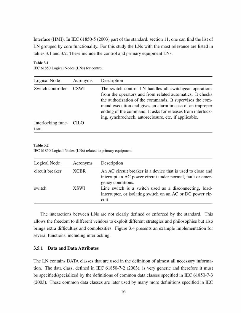
Interface (HMI). In IEC 61850-5 (2003) part of the standard, section 11, one can find the list ofLN grouped by core functionality. For this study the LNs with the most relevance are listed intables 3.1 and 3.2. These include the control and primary equipment LNs.
Table 3.1IEC 61850 Logical Nodes (LNs) for control.
Logical Node Acronyms Description
Switch controller CSWI The switch control LN handles all switchgear operationsfrom the operators and from related automatics. It checksthe authorization of the commands. It supervises the com-mand execution and gives an alarm in case of an improperending of the command. It asks for releases from interlock-ing, synchrocheck, autoreclosure, etc. if applicable.
Interlocking func-tion
CILO
Table 3.2IEC 61850 Logical Nodes (LNs) related to primary equipment
Logical Node Acronyms Description
circuit breaker XCBR An AC circuit breaker is a device that is used to close andinterrupt an AC power circuit under normal, fault or emer-gency conditions.
switch XSWI Line switch is a switch used as a disconnecting, load-interrupter, or isolating switch on an AC or DC power cir-cuit.
The interactions between LNs are not clearly defined or enforced by the standard. Thisallows the freedom to different vendors to exploit different strategies and philosophies but alsobrings extra difficulties and complexities. Figure 3.4 presents an example implementation forseveral functions, including interlocking.
3.5.1 Data and Data Attributes
The LN contains DATA classes that are used in the definition of almost all necessary informa-tion. The data class, defined in IEC 61850-7-2 (2003), is very generic and therefore it mustbe specified/specialized by the definitions of common data classes specified in IEC 61850-7-3(2003). These common data classes are later used by many more definitions specified in IEC
16

Figure 3.4IEC 61850 Example for interaction of LNs for switchgear control, interlocking, synchrocheck, autoreclosure andprotection (IEC 61850-5 (2003)).
61850-7-4 (2003). As an example the LN circuit breaker, XCBR, contains one data class namedswitch position with a data name pos of the CDC Controllable Double Point - ”DPC”. The”DPC” CDC is composed of a list of 20 data attributes. Each attribute has a name, type, func-tional constraint, trigger option, value/value range, and an indication of whether the attributeis mandatory or optional. An example of a specific data attribute for the ”DPC” CDC is thedata attribute named ”stVal”, with an attribute type ”CODED ENUM” that can have a value ofintermediate-state, off, on or bad-state.
3.5.1.1 Control class model
DATA that provides controllable data attributes, as in the case of ”DPC”, ”SPC”, among others,follow a specific standard control model. This control model consist of specific services andbehaviors described with the use of state machines. These services are:
• Select / Select with value;• Cancel;• Operate;• Command termination.
The available behavior models, or state machines, are four:• Direct Operation with Normal Security;• Select Before Operate (SBO) with Normal Security;• Direct Operation with Enhanced Security;• SBO with Enhanced Security.
17

In Direct Operation the Operate command is sent directly to the object under control. In SBOcontrol, first a Select command must be sent that will put the machine in a privileged, exclusive,state (Ready state) and only then the Operate command can be issued. When in the Ready state,the Cancel command can be issued to resume normal operation (Unselected state). EnhancedSecurity differs from Normal Security in the Command termination.
3.6 ACSI and SCSM
The concept of the SCSM has been introduced to be independent from communication stacksincluding application protocols. One objective of the IEC 61850 series is the interoperabilityof devices. This requires that all communicating devices use the same communication stack.Therefore, the goal of this independence is not to have many mappings in parallel, but to beable to follow the state of the art in communication technology. This means that all the abstractinformation and service models defined in parts IEC 61850-7-4 (2003), IEC 61850-7-3 (2003)and IEC 61850-7-2 (2003) must be mapped to standardized communication systems as definedin parts IEC 61850-8-x. Already defined and in use by the standard, IEC 61850-8-1 (2004) part,defines the mapping to MMS, Transmission Control Protocol (TCP)/Internet Protocol (IP), andISO/IEC 8802-3.
Referring at the ISO/Open Systems Interconnection (OSI) stack layers we can say that lay-ers 1 and 2 are mapped to Ethernet while layers 3 and 4 into TCP/IP and layers 5 to 7 intoMMS. MMS is written in Abstract Syntax Notation One (ASN.1) notation, refer to Dubuissonand Fouquart (2000) for literature on the subject, and it is mapped to TCP/IP by Request ForComments (RFC) 1006, Marshall T. Rose and Dwight E. Cass (1987). Time critical messageslike Sampled Analog Values (SAV) and Generic Object Oriented Substation Events (GOOSE)are mapped directly to the Ethernet layer. GOOSE data is directly embedded into Ethernetdata packets and works on publisher-subscriber mechanism on multicast or broadcast MACaddresses. Several other mechanisms are used in order to assure communication speed andreliability. SAV goes out of the scope of this work and is not examined here.
A brief but clear overview of the standard application is provided in Brand (2004). A slightlymore detailed one can be consulted in Baigent et al. (2005). Readers further interested in thetesting procedures can refer to Udren and Dolezilek (2006).
18

Chapter 4
Simulation Platforms and Simulation Models
4.1 Introduction
A model is a representation of an object, concept or system. This representation can be abstractor physical, static or dynamic. Generally, since most problems of interest in the real worldare usually too complex, the model represents an abstract view where assumptions and simpli-fications are made of the complex reality. In this sense, simulation is nothing more than themanipulation of the designed model in order to mimic the real object, concept or system understudy. A careful balance of the model complexity must be exercised. A too complex modelmight reduce the simulation performance to an impractical point. A too simple model mightintroduce errors soo big that the results are totally inaccurate.
The advent of the computer and its rapid growth and widespread use allowed the field ofcomputer simulation to expand alongside. When traditional methods, like analytical solutions,are unable to provide results the computer simulation methods can still be employed. Computersimulation provides several benefits and advantages over pure analytical methods. It can beused in the optimization of systems, performance and/or reliability wise. It can also be used toverify correctness of designs before production. It can provide a virtual environment for trainingpurposes. Different models for factories, communications and computer networks, integratedcircuits, and all other sorts of systems have already been constructed. Some disadvantages liketime consuming and expensive to build models, extensive training and experience required arealso part of the simulation area.
In order to avoid the inherent disadvantages of using simulation, several platforms withdifferent characteristics have been developed. Simulation platforms can be classified as eitherbeing discrete or continuous depending on the way the simulation objects are manipulated. Inthe discrete type of simulation the system operation is represented as a chronological sequenceof events where each event occurs at an instant in time and produces a change of state in thesystem. This time progression can be event based (steps with variable length) or incremental(stepped, fixed length).
4.1.1 Simulation platform
The sole task of evaluation and decision for a specific simulation platform is a complete study initself as also identified in Albrecht (2010). There are many choices each with it’s own character-
19

istics. The project itself also has some very specific requirements and to the author knowledgethere is currently no simulation models available for the Substation Automation System (SAS)field. The project also makes extensive use of communication networks and for that reasonseveral network simulators were looked at in order to make a decision. The decision in thiswork ended up being on using OMNeT++ simulation framework. At the moment of this writingversion 4.1 is the latest stable version and as such this was the used version. The next paragraphprovides part of the reasoning that supported this decision.
The motivation of developing OMNeT++ was to produce a powerful open-source discreteevent simulation tool that could be used by academic, educational and research-oriented com-mercial institutions for the simulation of computer networks and distributed or parallel systems(Varga (2010)). The fact that OMNeT++ follows a framework approach allows the independentdevelopment of OMNeT++ and the specific application areas frameworks. Already several uni-versity research groups and non-profit research institutions use OMNeT++ and companies likeIBM, Intel, Cisco, Thales and Broadcom are also using OMNEST1 successfully in commercialprojects or for in-house research (Varga and Hornig (2008)). These were important factors forthe decision but OMNeT++ also had important design requirements. Enabling large-scale sim-ulation, simulation models need to be hierarchical, and built from reusable components as muchas possible. The simulation software should be modular, customizable and should allow embed-ding simulations into larger applications. Data interfaces should be open: it should be possibleto generate and process input and output files with commonly available software tools. Severalsimulation tools were also compared in Varga and Hornig (2008): NS-2, J-Sim, SSFNet, JiSTand SWANS, OPNET and QualNet. NS-2 despite being one of the most widely used it doesnot provide some of the requirements for the project and/or introduce drawbacks. An importantone being its focus only on network simulation and the fact the models are contained withinthe supporting infrastructure. J-Sim, SSFNet, JiST and SWANS projects have a reduced activ-ity. OPNET is based on C and it’s models are of fixed topology stored in a proprietary format.OMNeT++ is open-source modular and versatile.
4.2 OMNeT++ simulation platform
OMNeT++ is a component based, modular and open architecture for discrete event simulation.Because of its extensibility, on-line documentation and free academic license it is a popular
1OMNEST and OMNeT++ are largely identical, and simulation models written for one areguaranteed to compile and run with the other. Differences apply to licensing, packaging, andcertain features only (Simulcraft, Inc. (2011)).
20

choice in academia. OMNeT++ itself does not simulate anything in particular but rather pro-vide a common framework that can be used or extended by users to create any simulation modelrequired. Because of this characteristic, domain specific functionality is developed and pro-vided as independent projects. Currently there are already extensions for real-time simulation,network emulation, alternative programming languages (Java, C#), database integration, SystemC integration, and several other functions (OMNeT++ Community (2011)).
4.2.1 Overview
OMNeT++ is an event based simulation platform on which the events are modeled as messages.It’s working principle consists on modules that communicate by passing messages betweeneach other or themselves, triggering the events. The modules contain gates that are used forconnection to other modules and for the transmission of messages. All sent messages go intoa global queue and are time ordered. An entity called the scheduler is responsible to retrievethe messages from the queue and deliver them to their destination module. The lowest levelmodules are called simple modules and these can be grouped into compound modules to forman hierarchy. The hierarchy can have unlimited levels and the whole model, being itself alsoa compound model, is called network. A graphical representation of this hierarchical structurecan be seen in Figure 4.1. In this example we can observe the Network module, simple modulesconnected by gates and a compound module made of different simple modules and a gate.
Simple moduleSimple moduleSimple module
Compound module
Network
Figure 4.1OMNeT++ simple and compound module types example. One Network composed by a simple and a compoundmodule, itself composed of 2 simple modules. Compound modules agglomerate other modules, both simple andcompound, while simple modules provide C++ implementations (omnetpp41).
All modules derive/subclass from the cSimpleModule class. This class provides severalvirtual implementations for specific modules to derive their own implementations. The logicbehind it includes an initialize and a finish function that are called on simulation initialization
21

and finalization respectively. The handleMessage should contain all the internal logic requiredfor the implementation by using the message sending/receiving functionality. Using this struc-ture a timer can, for example, be easily implemented by programming the module to send ascheduled message to itself (self messaging concept) upon initialization. Listing 4.1 contains asmall excerpt from the cSimpleModule class.
30 /∗ ∗31 ∗ Base c l a s s f o r a l l s i m p l e module c l a s s e s . cSimpleModule , a l t h o u g h packed32 ∗ w i t h s i m u l a t i o n −r e l a t e d f u n c t i o n a l i t y , does n o t do a n y t h i n g u s e f u l by i t s e l f :33 ∗ one has t o s u b c l a s s from i t and r e d e f i n e one or more v i r t u a l member34 ∗ f u n c t i o n s t o make i t do u s e f u l work . These f u n c t i o n s are :35 ∗36 ∗ − v o i d i n i t i a l i z e ( )37 ∗ − v o i d handleMessage ( cMessage ∗msg )38 ∗ − v o i d a c t i v i t y ( )39 ∗ − v o i d f i n i s h ( )40 ∗41 ∗ i n i t i a l i z e ( ) i s c a l l e d a f t e r \opp c r e a t e d t h e module . Mul t i−s t a g e42 ∗ i n i t i a l i z a t i o n can be a c h i e v e d by r e d e f i n i n g t h e i n i t i a l i z e ( i n t s t a g e )43 ∗ method i n s t e a d , and a l s o r e d e f i n i n g t h e n u m I n i t S t a g e s ( ) c o n s t method t o44 ∗ r e t u r n t h e r e q u i r e d number o f s t a g e s .45 ∗46 ∗ One has t o r e d e f i n e handleMessage ( ) t o c o n t a i n t h e i n t e r n a l l o g i c o f47 ∗ t h e module . handleMessage ( ) i s c a l l e d by t h e s i m u l a t i o n k e r n e l when t h e48 ∗ module r e c e i v e s a message . ( An a l t e r n a t i v e t o handleMessage ( ) i s49 ∗ a c t i v i t y ( ) , b u t a c t i v i t y ( ) i s n o t recommended f o r s e r i o u s model d e v e l o p m e n t50 ∗ because o f s c a l a b i l i t y and debugg ing i s s u e s . a c t i v i t y ( ) a l s o t e n d s t o l e a d51 ∗ t o messy module i m p l e m e n t a t i o n s . )52 ∗53 ∗ You can send ( ) messages t o o t h e r modules , or use s c h e d u l e A t ( ) +c a n c e l E v e n t ( )54 ∗ t o imp lemen t d e l a y s , t i m e r s or t i m e o u t s . Messages s e n t or s c h e d u l e d ( b u t55 ∗ n o t c a n c e l l e d ) are d e l i v e r e d t o modules v i a handleMessage ( ) , or , when u s i n g56 ∗ a c t i v i t y ( ) , v i a r e c e i v e ( ) .57 ∗58 ∗ The f i n i s h ( ) f u n c t i o n s are c a l l e d when t h e s i m u l a t i o n t e r m i n a t e s59 ∗ s u c c e s s f u l l y . T y p i c a l use o f f i n i s h ( ) i s r e c o r d i n g s t a t i s t i c s c o l l e c t e d60 ∗ d u r i n g s i m u l a t i o n .61 ∗62 ∗ @ingroup SimCore63 ∗ /64 c l a s s SIM API cSimpleModule : p u b l i c cModule / / i m p l i e s noncopyab le65 {66 f r i e n d c l a s s cModule ;
92 p r o t e c t e d :
115 v i r t u a l vo id hand leMessage ( cMessage ∗msg ) ;
Listing 4.1Partial C++ header file for cSimpleModule class. File taken from OMNeT++ version 4.1 source code.
22

4.2.2 Compiling and execution
An OMNeT++ model consists of several parts. Topology description files (NED files), messagedefinition files (MSG files) and C++ code for simple modules implementation. In order to builda simulation program first MSG files must be translated into C++ code. The MSG files arewritten in a specific language and require parsing with a tool provided by OMNeT++. Afterthis step is done, then all C++ code is compiled and linked together. The resulting executabledynamically loads the NED files and the simulation executes. NED files are written in a specificNED language. Inputs are provided by the use of command line arguments and also an INIfile containing simulation parameters and program configuration options. The outputs can beanalyzed using either command line tools or the provided Graphical User Interface (GUI) withfeatures such as sequence chart diagrams.
Since NED files are loaded dynamically at run-time, after a simulation model has beencompiled one can easily change them and execute different simulations, e.g. for testing differentnetwork topologies. On a properly conceived model this can be easily done because, besidesbeing very descriptive and extensible, NED topology files are written in plain text. The outputfiles are also easily exported since their contents follow a strict set of rules and they are alsowritten in plain text.
Listing 4.2 presents an example NED file where one can observe the syntax for describing anetwork with sub-modules and connections. A concept not yet mentioned that can be observedon this example is that of a channel. The modules are not simply connected by gates but thereis also a channel that represents the medium on which the messages travel between gates. Inthis example, the channel used accepts a datarate parameter since it attempts to represent acommunications network.
1 / /2 / / A ne twork3 / /4 network Network5 {6 submodules :7 node1 : Node ;8 node2 : Node ;9 node3 : Node ;
10 . . .11 c o n n e c t i o n s :12 node1 . p o r t ++ <−−> { d a t a r a t e =100Mbps ;} <−−> node2 . p o r t ++;13 node2 . p o r t ++ <−−> { d a t a r a t e =100Mbps ;} <−−> node3 . p o r t ++;14 node3 . p o r t ++ <−−> { d a t a r a t e =100Mbps ;} <−−> node1 . p o r t ++;15 . . .
23

16 }
Listing 4.2This NED code defines the architecture of a network type named Network with nodes of type Node and it’sconnections (Varga (2010)).
4.2.3 Architecture
The platform is composed of several different libraries. Sim contains the simulation kernel andclass library. Envir contains the code common to the different interfaces. Also in this librarythe main application entry point can be found. The main purpose of Envir library is to interfacewith Sim and the executing model while hiding the interface implementation details. This wayone can replace the interface, easily without having to touch other libraries. Cmdenv and Tkenv
are specific user interfaces implementations provided by default with OMNeT++. Cmdenv is acommand line interface that executes in the console/shell and Tkenv is a GUI implemented inTCL/TK. Tool Command Language (TCL) is a programming language and Tk is a graphicaluser interface toolkit used by TCL. The Model Component Library and the Executing Modelare not really libraries in itself but rather abstractions from the general principles of OMNeT++platform. OMNeT++ does not provide any Model Component by default. The user must builtit’s own components by deriving from the cSimpleModules or using already built frameworkslike INET. The Executing Model is built during execution by reading the NED topology files andloading the necessary models from the library. This general architecture overview of OMNeT++can be observed on the graphical representation in figure 4.2.
SimEnvir
CMDENVor
TKENVor ...
ExecutingModel
ModelComponent
Library
Figure 4.2OMNeT++ architecture (Varga (2010)).
OMNeT++ also depends on external libraries like pthread, libxml2, zlib, iconv and tcl/tkand other more peripheral/utilitarian libraries like common, layout, etc., not represented here.
24

4.2.4 Extensibility
No single platform can provide the needs of all user simulations. OMNeT++ accepts this and isbuilt with extensibility in mind by using Object-Oriented Design (OOD) principles. Any libraryand/or part of a library is easily replaced and/or extended provided one follows the existingApplication Programming Interface (API) interface. Commonly one could wish to extend theoutput classes, in order to use a specific output format or to have a direct connection withsome output processing application. Also extending and/or replacing the user interfaces. Andcomplete integration with another application by embedding OMNeT++ simulation into it.
OMNeT++ manual provides some examples and starting points/guidelines in order to ex-tended and embed the simulation framework. On listing 4.3 one can see a possible exampleimplementation of a user interface by deriving from EnvirBase.
1 # i n c l u d e ” e n v i r b a s e . h ”2
3 c l a s s FooEnv : p u b l i c Env i rBase4 {5 . . .6 } ;7
8 Regis te r OmnetApp ( ” FooEnv ” , FooEnv , 30 , ” an e x p e r i m e n t a l u s e r i n t e r f a c e ” ) ;
Listing 4.3Example user interface implementation. Example taken from version 4.1 of OMNeT++ on-line manual.
25

Chapter 5
Development
5.1 Overview
In order to better define the context of this work lets first start by looking at the Energy PowerSystem (EPS). After, the substation and its automation systems will be introduced with thecurrently available tools, its current limitations and finally the project contributions. We start bymaking simple assumptions and providing practical examples and slowly build the complexitytowards the project goals and objectives.
5.1.1 The Energy Power System
The EPS is composed of several substations. These substations can be geographically spreadand they are interconnected to form e.g. the EPS transmission system. It’s main purpose isthe bulk transfer of electrical energy, from generating power plants to substations located nearpopulation centers. This means that these connections form a network but refer only to electri-cal conductors. However, there is also a requirement to control and manage this network andconsequently the substations. This happens, for instance, when a failure occurs in one of thesesubstations. In order to prevent such a failure to propagate through the entire network (grid) andcause a major blackout (cascading failure), mechanisms to prevent it must be in-place. This ispart of the functions of the control and management system. As an example, this system canenable parts of the network to be disconnected to prevent further fault propagation. Later thefailing equipment can be fixed and/or replaced and the concerning network part reconnectedagain. This restores the energy back to the affected areas and prevents other areas from evennoticing the problems. A simplistic, but appropriate, view of the control and management sys-tem, is that of a main Control Center (CC) connected via a communications network to oneor more substations, like figure 5.1 shows. From the CC, the transmission system grid can bemonitored, and controlled if necessary, by an operator (user). This user can be a human or anautomated system. Currently most protection schemes involve an automation system and thehuman operators are relegated to monitoring and management functions. Usually the interfacebetween the user and the system involves a single or a network of computers running a GraphicalUser Interface (GUI). It is commonly referred to simply as a Human Machine Interface (HMI).The HMI GUI must present to the user, in an easy, clear and fast way, all the information heneeds to perform his duties effectively and efficiently. This usually involves some graphical
26

representation of the network substations (nodes) and its connections. It is also common tocontain other relevant information like current system states and values, e.g., connected/discon-nected, nodes voltage and/or current, etc. It can be a complete or partial representation of thenetwork depending on the user needs. This global picture forms what is commonly known asa Supervisory Control And Data Acquisition (SCADA) system. This acronym can, and in factis, also used in other systems besides the Energy Power System (EPS), like industrial processes.Figure 5.1 contains a representation of a possible EPS with both the electrical connections forpower transmission and the communications network for data acquisition and control.
Control Center (CC)
Substation CSubstation BSubstation A Substation D Substation E
SAS A SAS B SAS C SAS D SAS E
Switchyard A Switchyard B Switchyard C Switchyard D Switchyard E
Communication link
Electrical connections
Figure 5.1Energy Power System diagram with the electrical (bottom) and the communication (top) networks. TheSubstation Automation Systems (SASs) control and maintain the electrical connections in the switch-yard.Control commands can also be sent from the Control Center (CC) or other SASs for coordinated control.
5.1.2 The substation
The substation is composed of several different equipment. These equipment is divided into twocategories commonly named primary equipment and secondary equipment. From the previoussection one can also identify two different type of connections, to and from the substation: theelectrical connections and the communication link that is part of the control and managementsystem, figure 5.1.
The primary equipment category groups all the equipment concerned with the electricalconduction and transformation. From figure 5.1 this means all the equipment in the switch-yards. From the previous example this refers to the switch that connects, or disconnects, thesubstation from the rest of the grid. This includes also other type of equipment besides theswitches but, commonly, the equipment and the space where it is located are named switchgearand switch-yard, respectively. It is common to find sources that refer to both only as switch-yard.
27

The secondary equipment refers to all other types of auxiliary equipment necessary for theoperation of the substation and that are not connected directly to the electrical connection. Fromfigure 5.1 this means all the equipment that is part of the SASs. In the example this refers to thedevice that is connected to the Control Center (CC) via a communication link and to the switchvia some other method. When the appropriate command is sent from the CC the device operatesthe switch. These devices that receive and interpret the commands and interact with the primaryequipment are named Intelligent Electronic Devices (IEDs).
Inside the substation the IEDs are connected to a local communication network and to theswitchgear (figure 5.3). It is common to connect IEDs to the switchgear with a serial link.Sometimes an optical link is used to avoid signal interferences due to the high voltages presentin the switch-yard. Usually the local network interacts with the main communication network,from the control and management system, via a gateway device. It is also frequent to havedifferent communication protocols being used by the local and global networks, meaning that,the gateway device must understand all communication protocols in use and act appropriately.Sometimes inside the substation there is also a local control room. This is usually referred tosimply as a Human Machine Interface (HMI). Just like the CC control room this HMI cansupport a GUI for local control and management. Commands issued from the CC are usuallyreferred to as remote (control) from the substation point of view. The commands issued locally(local control) take precedence over remote. The reasons for this are mainly of security andsafety nature. If a human needs to operate in the switch-yard, a change of state issued fromthe main CC, unaware of such human presence, would cause serious danger. For this reason,functions for interlocking are used extensively inside the substation. Continuing the previousexample, for human safety the switch could be connected to an interlocking device. This inter-locking device would stop any remote control if certain conditions are met. This could includethe position of another switch. Before entering the switch-yard, any human operator would flipthis switch and prevent the remote operation of the switch-yard, safeguarding his own life.
5.1.3 The Substation Automation System
The functions of a Substation Automation System (SAS) refer to tasks, which have to be per-formed in the substation. These are functions to control, monitor and protect the equipment ofthe substation and its feeders. In addition, there exists functions, which are needed to maintainthe SAS, i.e. for system configuration, communication management or software management(IEC 61850-5 (2003)).
The previous sections mention two important functions of the substation: switching andinterlocking. These are however, only two of the control functions for the substation. There is
28

also the need to take into account different types of substations that require different functionsfrom each other. A substation connecting a generating plant to the grid is certainly different fromone connecting hundreds of consumers to the grid. Substations can have different topologies,equipment and purposes.
Humans are usually slow and error prone when compared to a machine. For this reason mostof the functions inside the substation are automated. The Substation Automation System (SAS)is the name of the system containing all of the devices involved in the automatic control ofthe substation. This also accounts for commands generated by a human operator that are thenprocessed by the SAS.
5.1.4 The Substation Automation Systems standard
The IEC 61850 standard describes a data model of the substation while taking all of its re-quirements into account. Its data model provides all the information necessary for control andprotection functions but also the IEDs and the switchgear configuration. The standard also pro-motes a standardized engineering process and includes a comprehensive protocol conformancetesting procedures. A description language, Substation Configuration Language (SCL), writtenin Extensible Markup Language (XML) was also developed to promote the exchange of infor-mation between devices but also with other tools. Using an Object-Oriented (OO) paradigm,taking into account future extensibility, the model data and services, Abstract CommunicationService Interface (ACSI), are separated from the communication, Specific Communication Ser-vice Mapping (SCSM). This allows both to develop and evolve, keeping up with the latesttechnological developments, at their own pace without conflicts. The substation functions aredecomposed into smaller components, named Logical Nodes (LNs), and the standard allows thedistribution of these among several devices (IEDs).
These IEC 61850 features are also summarized in Brand et al. (2004). They not only coverthe communication protocols but also the entire substation engineering process.
5.1.5 KEMA testing and certification tools
KEMA is one of the companies currently involved in the testing and certification of the IEDs re-garding IEC 61850 standard. The target of such tests consider the internal object modeling, dataand services, and online configuration. Several third-party testing laboratories are also certifiedand regulated fr this standard, but KEMA laboratory has the highest possible classification level.Inside KEMA a tool named UniCA Client Simulator, referred to as the client or client simulatorfrom now on, has been developed and is used extensively for such purpose. The client, usually
29

running on a computer, is connected to a single IED. Several test cases, as specified in the stan-dard, are then executed. These involve the interaction between the client and the IED where forcertain actions from the client certain reactions from the IED are expected. The client is thenable to execute these actions, that are written using a scripting language, and to analyse the re-actions from the IED. The actions involve the communication mechanism and the exchange ofmessages from the standard domain. During testing a network analyzer is also used to monitorand log all messages in the network. At the end, if all conditions are met, a certificate can beissued to the specific IED stating it’s conformance with the IEC 61850 standard. This complexand thorough testing process also include mechanisms to report and to correct possible flawsand/or faults detected in the standard.
5.1.6 The limitations
A generic testing plan includes four categories: conformance testing of the devices (IEDs), thedistributed functionality testing, the interoperability testing and the global system performance(Haffar et al. (2010)). Currently the standard testing procedures ensures the conformance ofIEDs but it still cannot guarantee its distributed functionality, interoperability and global system
performance. Devices, e.g. from different vendors, may conform to the standard but still be un-able to inter-operate together in a seamless and fault free way. The standard does not specify anyfunctional logic, i.e. what should be, for instance, the algorithm and/or logic for interlocking.This fact and the lack of logic modeling contributes to the difficulty of ensuring interoperabilityand maybe interchangeability of devices (IEDs). Different vendors may implement differentstrategies and philosophies and there is no standardized way to describe the logic used in spe-cific IEDs. Some efforts are currently being done in order to include this in future editions ofthe standard (Moreno (2010)). The limitation resultant from the conformance only testing isalso highlighted in Haffar et al. (2010). The remaining tests, distributed functionality, inter-operability and system performance can all be viewed as SAS functionality and performancetesting.
5.1.7 The contribution
The current project aims, on a first stage, at developing a tool capable of Substation AutomationSystems (SASs) functionality and interoperability testing and later, on a second stage, it willbe extend into performance testing also. The SAS functions that this project test system willcover initially are the switching and interlocking. These two functions are widely used in all
30

substation projects and providing an easy to use and automated test system will contribute tosignificant savings in both time and money.
5.2 Test system definition
Having defined our goal to test the Substation Automation System (SAS) and its functionalitywe shall begin the problem definition by looking at it as a black box, figure 5.2. On top, theSAS communicates with the main Control Center (CC) by a communication network. On thebottom it is connected to the switchgear in the switch-yard by using several, possibly optical,serial links. In order to completely test it, one must be able to monitor and control both the CCand the switchgear. The CC might be interested in a specific state of a specific switchgear. Bycontrolling both, the test system is able to change this switchgear state and then to expect thecorrect state to be communicated back to the CC. Now to further develop this we must startlooking inside the SAS, see figure 5.3. The SAS itself is composed of several different com-ponents. The typical SAS will contain one or more IEDs, a Gateway and a HMI all connectedtogether in a local network.Gateway: The Gateway is mainly a device that interconnects the communication networks
from the main CC with the local network. Commonly these networks are of differentnature and also use different protocols. In this sense the Gateway acts as a translator andalso a barrier. In certain situations the Gateway can itself be also an IED.
IED: The IEDs are mainly the devices that operate the switchgear. Therefore they must beconnected to the local network and also to the switchgear. This is not always the case, ife.g. the function of a specific IED is to record and store in a database the transient voltagevalues of a specific switchgear. In the case that there is already another IED connectedand serving this information from the switchgear (server role). Then the IED only requiresa connection to the local network and to the database. The required information is thenacquired from the server IED in the local network (client role). Client-server relationshipbetween both IEDs, paradigm used in the IEC 61850 standard.
HMI: Just like the control room from the CC certain substations also provide a local humanaccess for interaction with the SAS and the equipment. This is mainly just referred to asthe HMI but usually it consists of a room with a computer running a GUI.
5.2.1 Test system requirements
Following the work proposed in Schimmel (2008) the basic requirements for such a testingsystem are summarized as effectiveness and efficiency.
31

Control Center (CC)
Substation AutomationSystem (SAS)
Switchyard
Control Center (CC)
GatewayHMI
IED IED
Switchyard
IEC 61850
Figure 5.2Substation Automation System (SAS) as ablack box. On top it communicates with theControl Center (CC) while on the bottom it’shardwired to the switchyard (Schimmel(2008)).
Figure 5.3Substation Automation System (SAS) insideview. The different components of theSubstation Automation System (SAS)(Schimmel (2008)).
Effectiveness refers to the market value and the contribution of the test system to the field.An automated test system capable of moving time spent on Site Acceptance Test (SAT) to Fac-tory Acceptance Test (FAT) provides significant savings to all substation projects. Automatedtest procedures improve the time spent on testing but also reduce the probability to introducenew errors. This is also mentioned in Haffar et al. (2010) as a key demand from end users (util-ities). Testing of switching and interlocking, being two widely used functions, allows such anautomated system to capitalize the needed improvements on time spent testing.
In order to be efficient the test system requires to be flexible and automated. Automationmust enable fast test execution, reproducible test results, archiving and analysis of test results.Flexibility must enable the application of the test system to many different systems while pro-viding an easy configuration. Requirements such as no, or minimum, human intervention and noneed for highly experienced test engineers contribute to both flexibility and automation. Otherrequirements include the ability to simulate missing devices, analysis of 61850 messages and atime stamp accuracy of at least 1 millisecond. According to the standard definition every mes-sage contains a maximum response time or Time To Live (TTL). Certain messages, according toimportance, have only a few milliseconds TTL hence the time stamp accuracy of 1 millisecond.A slower performing test system could not guarantee such response times and properly test thesystem. The ability to simulate missing devices makes the system scalable allowing the testingof small parts before the complete SAS test. The purposed solution in Schimmel (2008) forflexibility is to build the test scenarios as scripts and having a pre-built collection of templates.The executable tests are then generated as necessary from the templates. Because they are meant
32

to be written using a high level scripting language this allows the easy adjustments for specificdetails of certain SAS. The easy configuration is achieved by using the configuration languageprovided by IEC 61850 standard, SCL. The necessary file would be the Substation Configu-ration Description (SCD) file that contains the complete description of the substation and itsdevices already configured. This means that in this XML file the complete substation architec-ture with the switchgear and it’s connections are described. The IEDs, with brand and model,and its complete description according to Logical Devices (LDs) and Logical Nodes (LNs). Itis also described the relation between each switchgear and the devices LNs it interacts with.
5.2.2 Test system components
From these requirements the complete test system can then be decomposed into several compo-nents. This decomposition can be observed graphically in figure 5.4.Test master - Test scripts: The Test master is the core of the testing system. Its main purpose
is to read the different test scripts and execute them. For that he will convert the specificscript actions into commands to the different components. Feedback from the componentscan also be received and appropriate actions executed. An example application would beto test the switching operation of a specific switchgear from the local Human MachineInterface (HMI). The script template would state the generic actions to take, i.e. sendoperation command to the IED that controls the switchgear and expect the switchgearstate to change into a specific value within a specific amount of time. If this final statehas the expected value and this occurs within the allowed time, then report the test caseas success; otherwise as failure and state the reasons. From this generic template the testsystem script engine must transform it into concrete test cases for each of the switchgearpresent in the specific substation under test. This means resolving and referring specificswitchgear and also the IEDs connected and related to the switching functionality of them.Then communicate to the different components such actions, i.e. for the current exampletelling the HMI simulator component to the send the command to the controlling IED.After that expect the feedback from the I/O system component reporting the switch statechanged within the time limit.
I/O System: Real IEDs connected to the switchgear must also be tested. In order to be able totest them the switchgear must be emulated. There are many different types of connectionsmost using serial communication, e.g., a connector with 100 V and 5 A or even opticallinks. Several manufacturers already provide such devices that can be connected to IEDsand that emulate the switchgear. This component is meant to represent such devices.
33

I/O driver: Since several different types of I/O Systems exist, the test system must be able tointerface with them. For that a driver implementation allows the test system to load thenecessary code for each of the different I/O Systems, hence the name of the component.
IED simulator: Several conditions support the need for a scalable test system, namely, testingsmaller parts of a complex substation first, or even trying to decide which IEDs to acquirebefore the investment is made. For this to be possible the missing IEDs must be simulated.This component responsibility is to simulate the behavior of a specific IED. Since eachdevice is different, different vendors and even different models behave differently, thiscomponent must also take that aspect into consideration. Having an IED library fromdifferent vendors supports this requirement.
HMI simulator: Part of the functionality of the SAS is to provide information and interact withthe local HMI (control room). Therefore this must also be tested. This is depicted herewith the HMI simulator component.
CC simulator: Like the HMI simulator, the CC simulator purpose is to simulate the function-ality used to/from the CC to the SAS. In reality, regarding IEC 61850 standard, the client-server model used doesn’t make any distinction from the server to the client point of view.This means the HMI and the CC (even other IEDs) access a server (an IED providinginformation) the same way. The only difference here is that the HMI has direct accessto the local network. The CC simulator must, depending also on substation, access theGateway device first. In the case the communication from CC to SAS is not IEC 61850based and the intention is also to test the Gateway then the CC simulator must also be ableto understand and use the other protocols in place, as it was mentioned earlier.
Analyzer: As with any true test or experiment, results must be recorded. For this reason theAnalyzer component exists. It’s main job is to monitor the network and record everything,or everything relevant, that is being transmitted in the local network. These results can bestored and analyzed later.
5.3 Test system prototype
OMNeT++ was the chosen simulation platform for the test system prototype. Based on theprevious test system definition, figure 5.4, the following components have been implementedand included in this prototype version.
Implemented Components:• Test master – Test scripts: The test scripts feature from this component will not be imple-
mented but certain small developments must be done in order to execute properly someinitial tests.
34

CC simulator
Test master – Test scripts
HMI simulatorI/O driver Analyzer
GatewayHMI
IEDIED IED simulator
I/O system
IEC 61850
Figure 5.4Test system definition components (Schimmel (2008)).
• IED simulator: The IED simulator will be implemented by integrating the Dynamic LinkLibrary (DLL) interface that contains the core functionality from KEMA tool, UniCAMulti-IED Simulator.
• I/O driver: This component is the interface between the test system and the I/O system.The I/O system will not be included in this version of the prototype but, despite the name,it is also implicit in this component the simulation model for the primary equipment. Thissimulation model was implemented under the name of process model.
The remaining components will not be included in this first stage prototype version but areplanned for later development.
Future versions components:• I/O system: This component requires hardware development or integration with hardware
currently available in the market. Because of the time necessary to development such asystem the obvious choice goes to the integration of third party hardware. Several devicesalready exist in the market and a study to decide which ones to support is required. Thischoice will affect the I/O driver component because specific drivers must be written tobecome part of the I/O driver library.
• Analyzer: The job of the analyzer is to record all communications in the local network.This initial version of the prototype will not devote time developing or integrating thiscomponent with other tools. Instead, one of the already available tools in the market wasused, KEMA UniCA Analyzer, by executing it as an independent process.
• CC simulator: This initial version of the prototype will not develop this component andKEMA UniCA Client Simulator will be used to replace it in the initial tests. This toolwill be executed as an independent process and commands emulating the scripts will beissued from it.
35

• HMI simulator: This initial version of the prototype will not develop this component andKEMA UniCA Client Simulator will be used to replace it in the initial tests. This toolwill be executed as an independent process and commands emulating the scripts will beissued from it.
The following section describes with more detail the development and implementation ofthe different components.Test master – Test scripts: The Test master should be able to read the test scripts and execute
actions accordingly. It also needs access to the remaining components of the simulationenvironment in order to interact with them. In OMNeT++ the scheduler already performssuch a similar central role. The implementation extended the scheduler in order to ac-commodate for the new requirements. The scripting functionality, reading and executingscripts, was not implemented. This requires a complete study on methods and languagesand for that reason it was not included in the initial prototype.
Scheduler: In order to extend the scheduler to accommodate the test system require-ments some changes had to be made. The requirements include the communication be-tween external devices. OMNeT++ simulation works internally by the exchange of mes-sages between modules. When interfacing with external devices, like real network inter-face cards, the scheduler is responsible to monitor such devices. When something relevantto the simulation happens in the devices the scheduler must generate the appropriate simu-lation model messages and deliver them to the relevant modules. This means the scheduleris tightly connected to the I/O driver and I/O system of the test system. Some termina-tion conditions, that will be explained in more detail later, had to be implemented in thescheduler for test termination.
Configuration: In order to keep the system configuration process simple, accordingto the requirements, the initial input to the test system is the SCD file. OMNeT++ requiresdifferent files formats for configuration (NED, MRT, INI). The different files must thenbe generated dynamically from the initial SCD file. This required the development ofa set of functions, grouped into a library called scl2ned. Figure 5.5 shows a graphicalrepresentation of this resulting process flow.
I/O driver: The I/O driver as described, is mainly a driver interface to other external devicesthat emulate the switchgear (I/O system). In reality several other implicit requirementsare necessary and part of the I/O driver. The switchgear must be simulated and that sim-ulation model must interact with different types of I/O systems but also with the IEDssimulation model. By using an abstract Application Programming Interface (API) forDLL development enables the loading of different device drivers at run-time. This alsodetaches the development of such drivers from the main test system allowing the creation
36

INI,NED,MRTfiles
scl2nedSCDfile
Executing Model Resulsfiles
Prototype test system
Figure 5.5Prototype process flowchart. A SCD file is ”fed” into the prototype that will generate the necessary files to executethe simulation.
of an independent I/O driver library. The simulation model for the switchgear is referredto as process model.
Process model: The process model must simulate the different switchgear and itsconnections to the IEDs. These IEDs can be both simulated and real devices. The simu-lated IEDs are part of the logic model simulation model. In this case function calls fromthe process model to the logic model were used. In the case of real devices a mecha-nism to interface with external devices that emulate/simulate the switchgear is necessary.These devices will then be physically connected to the real IEDs just like in the real sub-station environment. Such devices are already available by different vendors, such asOMICRON R©. Having an independent I/O driver library mechanism accounts for modu-larity, encapsulation and flexibility.
The process model classes were roughly based on the class models and hierarchy fromthe SCL structure. Figure 5.6 shows a short graphical representation (Unified ModelingLanguage (UML) class diagram) of the classes hierarchy used in the process part. Themain functionality implemented in the Switch class enables the opening and closing of theswitches. Two types of switches exist, disconnectors (DIS) and circuit-breakers (CBR),but in the current model both contain the same functionality. The class division of Con-
ductingEquipment and Equipment relates to equipment with one terminal connection only,such as voltage measurement equipment, and equipment with two terminals (conductingequipment such as current measurement).
IED simulator: The IED simulation model is part of the logic model. The logic model mustsimulate different IEDs models and behaviors but also the SAS local network. By usingalso a driver mechanism with an abstract API for DLL run-time loading it is possibleto develop different drivers, independently, each with its own characteristics. This IEDlibrary allows different development paths for different IEDs with different behaviors.
37
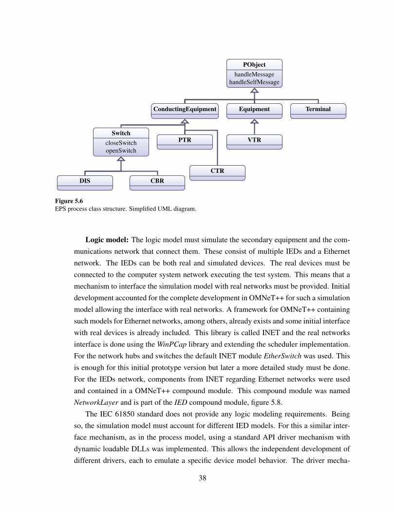
PObjecthandleMessage
handleSelfMessage
EquipmentConductingEquipment Terminal
PTR
CTR
SwitchcloseSwitchopenSwitch
DIS CBR
VTR
Figure 5.6EPS process class structure. Simplified UML diagram.
Logic model: The logic model must simulate the secondary equipment and the com-munications network that connect them. These consist of multiple IEDs and a Ethernetnetwork. The IEDs can be both real and simulated devices. The real devices must beconnected to the computer system network executing the test system. This means that amechanism to interface the simulation model with real networks must be provided. Initialdevelopment accounted for the complete development in OMNeT++ for such a simulationmodel allowing the interface with real networks. A framework for OMNeT++ containingsuch models for Ethernet networks, among others, already exists and some initial interfacewith real devices is already included. This library is called INET and the real networksinterface is done using the WinPCap library and extending the scheduler implementation.For the network hubs and switches the default INET module EtherSwitch was used. Thisis enough for this initial prototype version but later a more detailed study must be done.For the IEDs network, components from INET regarding Ethernet networks were usedand contained in a OMNeT++ compound module. This compound module was namedNetworkLayer and is part of the IED compound module, figure 5.8.
The IEC 61850 standard does not provide any logic modeling requirements. Beingso, the simulation model must account for different IED models. For this a similar inter-face mechanism, as in the process model, using a standard API driver mechanism withdynamic loadable DLLs was implemented. This allows the independent development ofdifferent drivers, each to emulate a specific device model behavior. The driver mecha-
38

nism is based upon the OMNeT++ simple module structure of initialize, handleMessage
and finish functions. This driver system was built inside the IEC61850 simple moduleimplementation. Upon initialization the IEC61850 loads the specified driver DLL.
In order to speed up development and quickly provide a simulated device for testing,a driver based on KEMA UniCA Multi-IED Simulator was implemented. This driver wasnamed kemaieddrv and it will be further detailed below in section 5.4.4. This enabledto skip the complete communication stack implementation in OMNeT++ and as such theuse of INET was not further explored. This is only necessary for a complete simulationenvironment tool and since this is currently not the goal of this project it was not pursued.Since this is also a useful feature the implementation was still done with INET function-ality included for a future development. The tool provided by KEMA already containsthe protocol implementation and the interface with a real network interface. A specialdriver interfaces with the logic model that provides the missing functionality. Listing 5.1contains part of the developed driver API for the logic model. The functions read dataset
and write dataset provide internal access to the IEC 61850 network stack.
44 / / DLL e n t r y f u n c t i o n ( c a l l e d on load , unload , . . . )45 BOOL APIENTRY DllMain ( HANDLE module , DWORD reason , LPVOID r e s e r v e d ) ;46
47 / / E x p o r t e d f u n c t i o n s and f u n c t i o n p o i n t e r s48 t y p e d e f void (∗ FP INITIALIZE ) ( d e v i c e i n f o t dev ) ;49 IED DRV API void i n i t i a l i z e ( d e v i c e i n f o t dev ) ;50 t y p e d e f void (∗FP HANDLEMESSAGE) ( d e v i c e i n f o t dev , m s g i n f o t msg ) ;51 IED DRV API void hand leMessage ( d e v i c e i n f o t dev , m s g i n f o t msg ) ;52 t y p e d e f void (∗ FP FINALIZE ) ( d e v i c e i n f o t dev ) ;53 IED DRV API void f i n a l i z e ( d e v i c e i n f o t dev ) ;54 t y p e d e f void (∗FP READ DATASET ) ( d e v i c e i n f o t dev , n o d e i n f o t node ) ;55 IED DRV API void r e a d d a t a s e t ( d e v i c e i n f o t dev , n o d e i n f o t node ) ;56 t y p e d e f void (∗FP WRITE DATASET ) ( d e v i c e i n f o t dev , n o d e i n f o t node ) ;57 IED DRV API void w r i t e d a t a s e t ( d e v i c e i n f o t dev , n o d e i n f o t node ) ;58
59 # e n d i f / / EPS DRIVERAPI
Listing 5.1When a driver name is specified the IEC61850 module will load the driver DLL and interface with it using thisAPI.
5.4 Architecture and libraries overview
The complete architecture with all the libraries and relations between them can be seen in fig-ure 5.7. Libraries with a blue background were developed for this project. GUI library wasdeveloped in C# since this allowed for a faster development of a functional GUI. Libraries
39

scl2ned, EPSEnvWrapper and WinPCapWrapper were developed in C++/CLI taking advantageof the vast .NET R© framework for faster deployment. The wrapper libraries exists only to pro-vide access to unmanaged code (C++) from within the GUI .NET R© framework managed code(C++/CLI and C#). The remaining libraries were all developed in C++ (unmanaged). The EPSand the INET library contain the simulation models. EPS is the name given to the OMNeT++library that contain the logical model and the process model. The executing model are instancesof objects based on the building-blocks (modules) provided by the simulation models, EPS andINET. This obviously change from substation to substation depending on their configurationand therefore the generated NED files.
SimEnvirExecuting
Model
INET EPS
EPSEnv
EPSEnvWrapper
GUI scl2ned
WinPCapWrapper
kemaieddrv WinPCap
DevelopedC++/CLI
DevelopedC#
DevelopedC++
ExternalC++
Dynamicobjects
Legend:
OMNeT++
Figure 5.7Test system prototype architecture. All developed libraries presented with a blue background. The executingmodel is composed of dynamic objects created at runtime from the NED files.
5.4.1 INET simulation model
In order to simulate the communications network and to communicate with external devices theINET framework version 20110225 was used. Quoting the INET website for it’s description:
40

“The INET Framework is an open-source communication networks simulationpackage for the OMNeT++ simulation environment. The INET Framework con-tains models for several wired and wireless networking protocols, including UDP,TCP, SCTP, IP, IPv6, Ethernet, PPP, 802.11, MPLS, OSPF, and many others.”
Containing most of the communications network models necessary it is a perfect choice forinitial development and prototyping. The provided scheduler example for real time interfacingwas expanded to accommodate the project needs. This interface is done in Windows by usingthe WinPCap library. Version 4.1.2 of this library was used. Some of the modifications requiredinclude changes in the WinPCap and WinSock2 logic in the scheduler.
This implementation was later dropped in order to use the core functionality from KEMAUniCA Multi-IED Simulator. This allowed a faster development time since this already includesthe communication stack (IEC 61850, MMS, RFC1006, etc) and the interface with real networkdevices.
5.4.2 EPS simulation model
In order to simulate the substation a new OMNeT++ framework (simulation model) named EPS
was created. This simulation model is in fact two different models, one for the primary equip-ment and another for the secondary equipment (IEDs) and its communication network. Theprocess model and the logical model simulation models. The process refers to the substationprimary equipment, the switchgear, the electrical terminal nodes, the bays, the voltage levels,etc. The logical refers to the substation secondary equipment, the IEDs, and it’s logical compo-nents according to the standard, the Logical Devices, Nodes and Data Attributes.
5.4.2.1 Process model
5.4.2.1.1 Compound Modules The scl2ned library builds the compound modules accordingto the modularization options provided by the user. By default no modularization is includedand all the primary equipment, simple modules, are connected directly to each other. The userhas the ability to choose the bay, voltage and substation or any combination of these as modular-ization levels. This groups all primary equipment within these levels inside the same compoundmodule.
5.4.2.1.2 Simple Modules The following simple modules were developed for the processmodel.
41

CBR and DIS (Switch) Both the CBR and DIS simple modules are subclasses of Switchand in essence they have the same functionality. In real life the difference between both isthat the CBR (circuit breakers) can also operate under fault conditions in order to open short-circuits. For the current simulator operation they both operate the same way but both simplemodules were developed in order to account for future needs and to keep the structure similar toreal-life and the way the standard describes it. Table 5.1 and 5.2 contain the module events andmain functionality description.
Table 5.1Switch (CBR and DIS) simple module events.
Event Origin Description
Open Switch XSWI LN Operate the switch to the open position.Close Switch XSWI LN Operate the switch to the closed position.
Timeout Self Self-message event to model the switch failure operation.Operate Self Self/message event to model the switch operation.
Table 5.2Switch (CBR and DIS) simple module functionality.
Action/Event Description
Operation When the events to operate the switch, closing and opening, are receivedthe timer events Timeout and Operate are setup (scheduled) and the switchstate is changed to indicate the in-transit operation. The predefined timevalues for the timeout and the operate are 10 milliseconds and 30 secondsand guarantee the normal switch operation, i.e. the timeout is bigger thanthe operate. In order to simulate specific equipment with operation timesdifferent than the defaults these need to be changed, this is done using theNED parameters feature that can be used to override the predefined values.They can also be easily changed to non-deterministic in order to simulateswitch failures probabilities. Currently they also assume that the openingand closing operations of the switch take the same amount of time, this canbe easily extended in the future.
Operate When the operate event is received the switch state is changed to reflect thenew stable state, open or closed, and the timeout event is removed from thescheduler.
Timeout When the timeout event is received the switch operation did not occurred asexpected, within the time limit, and the switch is put into the failure state.The operate event is removed from the scheduler.
42

Others The remaining simple modules, PTR, CTR and VTR, do not contain any function-ality yet as they are not relevant for the switching and interlocking. They were implementedjust in order to keep the real life and the standard structure. Also the scl2ned library will usethe class names of the standard directly from the SCL file into the NED topology file so if thoseclasses already exist as simple modules, even if empty, one does not need any logic mecha-nism to convert the names. The ConductingEquipment class specify the equipment with onlytwo terminal connections. The Equipment class specify the equipment with only one terminalconnection. The Terminal class allows multiple equipment to be connected together.
5.4.2.2 Logical model
The logical model was built incorporating the already existing INET modules for communica-tion. A compound module named IEDNetwork was created based on the INET modules fornetworking. This module is then contained in the compound module named IED that also con-tains an IEC61850 simple module. This implementation is partly exposed in listing 5.2 and canbe graphically observed in figure 5.8. The most relevant detail is inside the IEC61850 simplemodule. This module is provided with a specific driver DLL and upon initialization it loads thismodule to simulate a specific vendor and model IED behavior. The INET module chosen to beused for the network switches was the EtherSwitch. This decision will require a more detailedexamination later but for a working prototype/example is enough.
IED
IEC61850
IEDNetwork LD
...LN
...ethg
MMS
eth
Figure 5.8IED NED module developed for EPS simulation model.
13 module IED14 {15 parameters :
29 submodules :30 IEC61850 : IEC61850 {31 parameters :
43

32 d r i v e r = d r i v e r ;33 s c l = s c l ;34 i p = i p ;35 }36 NetworkLayer : IEDNetwork {37 t cpType = tcpType ;38 IPForward = IPForward ;39 namid = namid ;40 r o u t i n g F i l e = r o u t i n g F i l e ;41 n u m E x t I n t e r f a c e s = n u m E x t I n t e r f a c e s ;42 queueType = queueType ;43 }44 c o n n e c t i o n s a l lowunconnected :45 IEC61850 . mmsOut −−> NetworkLayer . mmsAppIn ++;46 IEC61850 . mmsIn <−− NetworkLayer . mmsAppOut++;47 IEC61850 . e t hO u t −−> NetworkLayer . e t h I n ;48 IEC61850 . e t h I n <−− NetworkLayer . e t h Ou t ;
Listing 5.2IED NED module partial listing implementation.
5.4.2.2.1 Compound Modules The following compound modules are included in the Logi-cal model, refer to figure 5.8 for a graphical representation.
IED The IED compound module represents the IED (secondary equipment). Inside it themodules with the Ethernet logic (IEDNetwork) and also the IEC 61850 logic and data model(LNs and LDs) are included.
IEDNetwork This compound module contains the modules from INET for Ethernet sim-ulation with some small additions to handle MMS messages. This is currently incomplete codeand it is not used to the current prototype tool since it is not needed for testing. In the future thiscode needs to be completed in order to completely simulate the substation.
LD The functional logic is included in the Logical Nodes (LNs) but these are groupedinside the Logical Devices (LDs). This was done in order to follow the IEC 61850 presentationand data modeling and to avoid having too many modules in the same hierarchy level, usefulwhen providing graphical representation of the hierarchy.
5.4.2.2.2 Simple Modules The following simple modules were developed for the logic model.
44

Logical Node (LN) XSWI The XSWI interfaces directly with the switching primary equip-ment, i.e. CBR and DIS. The state of the switch is monitored using a pooling approach and dur-ing configuration the primary equipment name and location must be setup. Tables 5.3 and 5.4list the module events and functionality description.
Table 5.3Logical Node (LN) XSWI simple module events.
Event Origin Description
Block Open CILO LN Prevent further Switch opening operations.Block Close CILO LN Prevent further Switch closing operations.Open Switch CSWI LN Operate the switch to the open position.Close Switch CSWI LN Operate the switch to the closed position.
Timeout Self Self-message event to model the timeout of theSelect Before Operate behavior.
Pooling Self Self-message event to pool current Switch posi-tion.
Subscription CSWI/CILO LNs Receive notifications of Switch positionchanges.
Logical Node (LN) CSWI The CSWI interfaces directly with the XSWI LN. Tables 5.5and 5.6 describe the module events and main functionality.
Logical Node (LN) CILO The CILO Logical Node (LN) implements the interlockinglogic. In this initial model a simple logic of state changes of a specific switch based on thecurrent state from another switch was implemented. Further future works must improve anddevelop further logic models. Tables 5.7 and 5.8 describe the events and main functionality ofthe module.
5.4.2.2.3 Others Other LNs from the standard were also implemented without any function-ality also because of the previously mentioned reasons, lack of interest to the currently intendedfunctionality and keeping the standard structure while avoiding unnecessary extra logics forclass names conversion.
5.4.3 ”scl2ned” library
The objective of the ”scl2ned” library is to read the Substation Configuration Description (SCD)file and to generate the NED topology files for the simulation engine. For this the file needs to be
45

Table 5.4Logical Node (LN) XSWI simple module functionality.
Action/Event Description
Blocking When the block command is received, for open and for closing, the XSWILN is put into a state that prevents any further, open or close, commands to beexecuted. This command accepts a boolean value for enabling and disablingthis feature.
Operation The operation is dependent on the control model used, see section 3.5.1.1.This control model is described, per LN, in the SCL file as it depends onconfiguration and setup. When an operate message to either open or close theswitch is received several conditions must first be verified. First the currentstate of the switch must be verified, if the switch is in a failure state or alreadyin the pretended state then no action is executed. Also if the command is toopen the switch and the block open event has been previously issued then noopening of the switch is possible. Likewise if the command is to close theswitch and the block close event has been previously issued then again noaction is possible.
Selection Depending on the control model used, before any operation the device datamust first be selected in order for the command to be accepted.
Timeout When the device data is selected the operation command must be issuedwithin a specific amount of time. If this timeout occurs and no command hasbeen issued then the device reverts back to the unselected state.
Pooling By default, every 1 millisecond, the XSWI LN queries the current state ofthe switch. If a change between the previous state and the current state isdetected all subscribed LNs receive an update event.
Subscribe Other LNs can subscribe to receive update event notifications whenever achange of state occurs in the switch.
Table 5.5Logical Node (LN) CSWI simple module events.
Event Origin Description
Open Switch HMI Operate the switch to the open position.Close Switch HMI Operate the switch to the closed position.
Timeout Self Self-message event to model the timeout of the Select Be-fore Operate behavior.
Update XSWI LN Change of state occurred in the subscribed LNs.
read using a XML parser while validating against the SCL schema for edition 1 of the standard.This builds a tree model, in memory, of everything described in the standard (substation, devices(IEDs), communication network and connections). From this model one can later generate all
46

Table 5.6Logical Node (LN) CSWI simple module functionality.
Action/Event Description
Configuration During initialization and configuration the CSWI LN subscribes to the con-nected XSWI LN in order to receive updated notifications whenever theswitch changes state.
Operation The operation is dependent on the control model used, see section 3.5.1.1.This control model is described, per LN, in the SCL file as it depends onconfiguration and setup. The command is relayed down to the XSWI inorder to operate the connected switch.
Selection Depending on the control model used, before any operation the device datamust first be selected in order for the command to be accepted.
Timeout When the device data is selected the operation command must be issuedwithin a specific amount of time. If this timeout occurs and no command hasbeen issued then the device reverts back to the unselected state.
Update When the CSWI is subscribed to a XSWI LN and the switch changes statethe update event notification is received.
Table 5.7Logical Node (LN) CILO simple module events.
Event Origin Description
Update XSWI LN Change of state occurred in the subscribed LNs.
Table 5.8Logical Node (LN) CILO simple module functionality.
Action/Event Description
Configuration During initialization and configuration the CILO LN subscribes to the moni-tored Switch.
Update Whenever the monitored Switch changes state the connect (or controlled)Switch is either blocked or unblocked depending on the logic implemented.
the necessary files by using different classes named serializers that traverse the tree while direct-ing the output to a stream (file). The different needed files are the NED topology files, the INIand the MRT files. Development of this library was done using C++/CLI language. This allowsaccess to the powerful .NET R© framework and provides a quick development environment.
47

5.4.3.1 NED serializer
The NED topology files are built by reusing the available modules from EPS framework. Hereseveral inputs from the user are necessary. These inputs include a selection of the driver DLLused by each of the IEC61850 modules, the network interface to use (if there is more than oneavailable) and input on how to serialize the substation. This input on how to serialize the sub-station refers to the dynamic logic introduced in order to consider different levels of substationas NED modules or not. This became a necessity after realizing that, except for the most simplesubstations, the graphical representation becomes too complex to be useful without modulariza-tion. Initially the default graphical model representation from OMNeT++ was being used, thismight also be a useful feature in the future for a simulation only or educational tool. Also nec-essary is the identification of the connection nodes that are electrical grounds and also busbars.This identification can more or less be automated by smart analysis of the substation model butmay also require user input. This allows the busbars graphical representation to be replaced bya bus and the ground terminals to be split and to add a ground graphical representation. Thissimplifies the graphical representation and avoids many overlapping connections. The main ideais to bring the graphical representation closer to that of the more familiar single line diagrampresent in most SCADA terminals. These two features already improve in this sense but furtherdevelopments need to be done. Since the GUI development was dropped in favor of a faster andsimpler to develop one (without graphical representation of the simulation model), no furtherwork was done in this direction.
In reality two different types of IED modules were developed. One named DRIVER containsthe driver functionality described above. The user is required to select a driver to be loaded bythe model. The other one, named CLIENT, refers to a IED module that contains no functionalityand hence does not require a driver. This necessity comes from the fact that several substationscontain many devices that are not relevant to the use of IEC 61850 standard. Occasionally onemay also require the simulation of certain devices within the substation but not all. This allowsmore control over the simulation environment and also on the resources required by it. TheNED serializer takes advantage of the inheritance properties provided by the NED languageand during serialization these different IED modules are built by subclassing the main IED
module.
5.4.3.2 INI serializer
The INI serializer is quite simple so far and just needs to account for some parameters that con-figure real interfaces and global simulation configuration options. This configuration is relatedto the WinPCap library and refers to the filter and network interface to use for each of the mod-
48
els. The global configuration options include the type of scheduler class used, the simulationtime granularity and output related options. In the future this will be expanded to accommodatefurther options and the code was implemented having this in mind.
5.4.3.3 MRT serializer
The INET framework interfaces can be configured by the use of a text file with a specific syntax.The syntax itself resembles the network configuration on a Linux machine. This text file endswith the MRT extension. The job of the MRT serializer is to read the communication anddevices model from the SCD and to generate these files automatically. Later the simulationengine will use them to configure the models interfaces.
5.4.4 Driver kemaieddrv
Based upon the API developed for the IEC61850 module, the driver named kemaieddrv wasdeveloped. This driver however implements an hybrid model. The driver provides access tothe IEC 61850 communication stack but the logic remains in the logic model. This decision isbased on time constraints. KEMA currently provides the UniCA Multi-IED simulator. This toolis already capable of simulating multiple IED devices. These devices comply to the IEC 61850standard but do not provide any logic functionality. So the logic model is extended to includethe logic functionality, normally expected to be inside the driver.
This allows the quick development of the IED simulator without requiring to build theIEC 61850 communication stack.
5.4.5 User interface
Initial tests and development were done using the user interface provided by OMNeT++ basedon TCL/TK technology. Soon this option was dropped in favor of an embedded user interface.This allows for a faster and better integration of the GUI with the simulation framework. Fol-lowing the recommendations in the OMNeT++ manual, the work was initially done, by copyingCmdenv and adding features and functionality as necessary. This involved the creation of a li-brary named EPSEnv in C++ and a wrapper library named EPSEnvWrapper in C++/CLI. Thiswrapper is necessary so that we are able to integrate it into the C# GUI. During execution thesimulation engine sends periodic reports to EPSEnv that contain several statistics about simu-lation execution along with console messages that are translated into a log window in the GUI.This allows the user to monitor the initialization, execution and finalization of the simulation incase of some unexpected errors occur. The GUI also provides a button that allows the user to
49

cancel and stop the currently running simulation. It was also necessary to develop in the GUI aconfiguration menu that allows the user to provide the input to the scl2ned library in an easy touse way. This menu presents to the user, after loading the SCL file, the complete loaded modelof the substation, devices and communication parts. Information was organized into differenttabs in order to better separate the different models and its configuration. There is also a logwindow in the configuration menu. This window allows the presentation to the user of warningsand errors found during the loading of the SCL due to nonconformities of the schema. In somecases these warnings and errors do not influence the outcome of the results, as when specificcompanies do not follow the standard strictly, and therefore must be evaluated by the user.
50

Chapter 6
Results
6.1 Testing tools and platforms
The testing environment was composed of a DELL OPTIPLEX R© GX620 desktop computer run-ning Windows XP R© Professional with Service Pack 3. This machine would host a VMWare R©
image, workstation 6.0 virtual machine version, of the same operating system version. In orderto provide some validity to the results the tool provided by KEMA, UniCASim 61850 ClientSimulator, would be used to issue commands to the devices in the simulation environment. Thistool is currently used in the Industry to test and certificate devices according to IEC 61850standard.
This setup was chosen for several reasons. No real Intelligent Electronic Devices (IEDs)were available for testing. Also the currently developed IED simulator, provided by kemaieddrv
library and the logic model, do not have Generic Object Oriented Substation Events (GOOSE)and reporting implemented yet. This makes it impossible, so far, to interact totally with realdevices. The usage of the UniCASim 61860 Client Simulator already proves that the alreadydeveloped part behaves correctly. Another reason is the fact the scheduler do not have yet ascripting engine developed. The commands could have been issued directly by the scheduler,hardcoded and without the manual work from UniCASim 61850 Client Simulator, behavinglike the test script. It was however decided that this would bring no real value to the test andthe setup used was more flexible. Changes could be made to the test, like a test script would,without the need to recompile the project.
6.2 Testing setup and environment
The guest operating system would run the simulator in a closed private network shared with thehost (host-only in VMWARE R© jargon). The host operating system would run the UniCASim61850 Client Simulator, referred from now on only as the client simulator.
For the test of the simulator the substation ”MAGNUM IGCC POWER PLANT 380kVSAS” was chosen. This substation is already large containing a completely and correctly de-scribed Substation Configuration Description (SCD) file, with approximately 1.633 kB, that iscorrectly read and parsed by the ”scl2ned” library. This substation contains 10 Bays and 29devices split among 4 subnetworks. In figure 6.1 part of the substation description, taken fromthe SCD file, is represented graphically in a single-line diagram. For the tests developed and
51

described in this work the equipment chosen was the disconnectors QC9 and QC1 from bayQ04.
AA1
Q03 Q04
QC1
QC9
Q05 (Bus coupler)
Q06
Figure 6.1Partial single-line diagram for MAGNUM AA1 substation. The test scenario focus on disconnectors QC1 andQC9 from Q04 bay. The complete substation contains 10 bays.
The devices and logical devices that are related to these equipment, referring from theSCD file, are AA1C1Q04A1 and LD0 respectively. Referenced, according to the standard, asAA1C1Q04A1/LD0. Specifically Logical Nodes (LNs) SXSWI7 and SXSWI5 are connected todisconnectors QC9 and QC1 respectively. Configuration and setup of the remaining LNs areclosely related to the logics modeling that is still missing in the standard. Since the logic mod-eling still needs to be further investigated and developed the following setup was decided forthis initial test, for no particular reason. LNs SCSWI7 and SCSWI5 were connected to LNsSXSWI7 and SXSWI5 respectively. LN SCILO7 would control the interlocking allowing theoperation of disconnector QC9 as long as disconnector QC1 would be in the opposite position(only on and off states were considered). The scheduler was configured to terminate success-fully when disconnector QC9 would achieve the state on while disconnector QC1 was also onthe on state and unsuccessfully otherwise. Both disconnectors would start in the off state. Referto table 6.1. Both SCSWI7 and SCSWI5 pos DATA were operating with Select Before Oper-ate (SBO) control model, according to the configuration options from the SCD file.
52

Table 6.1Ending conditions specified for the test scenario. The scheduler would monitor both devices and decide upon theconditions how to flag the test.
QC9 state QC1 state scheduler condition
off off continue execution (initial condition)off on continue executionon off terminate condition failureon on terminate condition success
Figure 6.2 shows a screen shot of the simulator taken during the configuration step of thedevices.
Figure 6.2Screen shot of the configuration menu while selecting the driver for device AA1C1Q04A1.
53

6.3 Execution
After configuring and setting up the simulation, according to the previous description, the testwas executed and a log file was generated. This log (ELOG) file is examined in detail anddiscussed in this section. Figure 6.3 shows a simplified graphical overview of the configurationand setup used.
AA1C1Q04A1
AA1 LD0
SXSWI5 SCSWI5
SXSWI7 SCSWI7
SCILO7
Logic Model
QC1
QC9
Process Model
Client Simulator(Test Scripts)
Test Master (Scheduler)
Real Ethernet(IEC 61850)
Figure 6.3Simplified graphical overview of the test scenario configuration and setup used.
All the required LNs initialized and configured correctly in the simulation environment.Listing 6.1 shows the relevant parts of the log regarding LNs initialization. All the initializationhappens at the predetermined time of 2 seconds (simulation time). This accounts for a default,but configurable, 2 seconds for device boot up. SCSWI7 and SCSWI5 both contain a CommonData Class (CDC) Pos with a control model SBO with enhanced security. Both SXSWI7 andSXSWI5 contain CDC BlkCls, BlkOpn and BlkUpd using direct with normal security controlmodels and also a Pos with a status only control model. Information summarized in table 6.2.
54

12051 E # 113 t 2 m 565 ce 0 msg 50712052 BS id 795 t i d 795 e i d 795 e t i d 795 c cMessage n ”AA1C1Q04A1LD0 / SCILO7 C o n f i g u r e
e v e n t ”12053 ES t 312054 − We are b eh i nd : 4 . 9 9 s e c o n d s
12072 E # 118 t 2 m 570 ce 0 msg 51212073 − AA1C1Q04A1LD0 / SCSWI5 : Pos Ct lModel sbo−wi th−enhanced−s e c u r i t y12074 BS id 815 t i d 815 e i d 815 e t i d 815 c cMessage n ”AA1C1Q04A1LD0 / SCSWI5 C o n f i g u r e
e v e n t ”12075 ES t 312076 − We are b eh i nd : 5 . 0 1 s e c o n d s
12082 E # 120 t 2 m 572 ce 0 msg 51412083 − AA1C1Q04A1LD0 / SCSWI7 : Pos Ct lModel sbo−wi th−enhanced−s e c u r i t y12084 BS id 823 t i d 823 e i d 823 e t i d 823 c cMessage n ”AA1C1Q04A1LD0 / SCSWI7 C o n f i g u r e
e v e n t ”12085 ES t 312086 − We are b eh i nd : 5 . 0 1 s e c o n d s
12188 E # 146 t 2 m 598 ce 0 msg 54012189 − AA1C1Q04A1LD0 / SXSWI5 : B l k C l s Ct lModel d i r e c t −wi th−normal−s e c u r i t y12190 − AA1C1Q04A1LD0 / SXSWI5 : BlkOpn Ct lModel d i r e c t −wi th−normal−s e c u r i t y12191 − AA1C1Q04A1LD0 / SXSWI5 : BlkUpd Ct lModel d i r e c t −wi th−normal−s e c u r i t y12192 − AA1C1Q04A1LD0 / SXSWI5 : Pos Ct lModel s t a t u s −o n l y12193 BS id 927 t i d 927 e i d 927 e t i d 927 c cMessage n ”AA1C1Q04A1LD0 / SXSWI5 C o n f i g u r e
e v e n t ”12194 ES t 312195 − We are b eh i nd : 5 . 0 2 s e c o n d s12196
12197 E # 147 t 2 m 599 ce 0 msg 54112198 − AA1C1Q04A1LD0 / SXSWI6 : i e c 6 1 8 5 0 module n o t c o n f i g u r e d , s l e e p i n g ! ! !12199 − We are b eh i nd : 5 . 0 2 s e c o n d s12200
12201 E # 148 t 2 m 600 ce 0 msg 54212202 − AA1C1Q04A1LD0 / SXSWI7 : B l k C l s Ct lModel d i r e c t −wi th−normal−s e c u r i t y12203 − AA1C1Q04A1LD0 / SXSWI7 : BlkOpn Ct lModel d i r e c t −wi th−normal−s e c u r i t y12204 − AA1C1Q04A1LD0 / SXSWI7 : BlkUpd Ct lModel d i r e c t −wi th−normal−s e c u r i t y12205 − AA1C1Q04A1LD0 / SXSWI7 : Pos Ct lModel s t a t u s −o n l y12206 BS id 935 t i d 935 e i d 935 e t i d 935 c cMessage n ”AA1C1Q04A1LD0 / SXSWI7 C o n f i g u r e
e v e n t ”12207 ES t 312208 − We are b eh i nd : 5 . 0 2 s e c o n d s
Listing 6.1Initialization of devices logical nodes
Initially one attempt to activate the QC9 disconnector was made using the client simulatorto connect and operate to SCSWI7 by following the correct procedures for SBO control model.The command was successfully denied and QC1 remained in the off position. Listing 6.2 showsthe relevant events of the log file. Since SCSWI7 is working on SBO mode, one must first
55

Table 6.2LNs CDCs Control Models as loaded and configured from the SCD file into the simulation.
Control Model (CDC)
LN Pos BlkCls BlkOpn BlkUpd
SCSWI5 SBO with enhanced security – – –SCSWI7 SBO with enhanced security – – –SXSWI5 status only direct, normal direct, normal direct, normalSXSWI7 status only direct, normal direct, normal direct, normal
select the object before executing the command. The Select command is accepted correctly attime 14.12 seconds (simulation time) as can be observed by the change of the state to Ready
state. listing line number 316190. At time 15.287 seconds, approximately one second later,the Operate command is sent and fails due to a block closing restriction in SXSWI7 controlledby SCILO7. listing line number 351202. The long time between the Select and the Operate
commands is due to the fact that the client simulator is being executed manually.
316187 E # 50838 t 14 .12 m 572 ce 50833 msg 822316188 BS id 825 t i d 825 e i d 825 e t i d 825 c cMessage n ”AA1C1Q04A1LD0 / SCSWI7 Timeout e v e n t ”316189 ES t 44 .12316190 − AA1C1Q04A1LD0 / SCSWI7 : Pos s t a t e changed t o Ready316191 BS id 822 t i d 822 e i d 822 e t i d 822 c cMessage n ”AA1C1Q04A1LD0 / SCSWI7 P o o l i n g e v e n t ”
pe 50838316192 ES t 14 .121316193 − We are b eh i nd : 53 .568 s e c o n d s
351200 E # 56673 t 15 .287 m 572 ce 56668 msg 822351201 CE id 825 pe 50838351202 − AA1C1Q04A1LD0 / SXSWI7 : S w i t c h O p e r a t i o n b l o c k e d due t o B l k C l s !351203 − AA1C1Q04A1LD0 / SCSWI7 : Pos s t a t e changed t o U n s e l e c t e d ( Opera te FAILED )351204 BS id 822 t i d 822 e i d 822 e t i d 822 c cMessage n ”AA1C1Q04A1LD0 / SCSWI7 P o o l i n g e v e n t ”
pe 56673351205 ES t 15 .288351206 − We are b eh i nd : 59 .081 s e c o n d s
Listing 6.2Attempt at operation of disconnector QC9 while QC1 is in forbidden state.
Then QC1 disconnector was changed state by operating SCSWI5 following also the SBOcontrol model. The command was successfully interpreted and the disconnector was success-fully operated. Listing 6.3 shows the relevant parts of the log file. Just like previously, the objectmust first be selected before operation. The difference is that the operate is accepted success-fully, as observed by the change of state to WaitForChange at time 18.094 seconds. Listingline number 435419. After the command propagates downwards from SCSWI5 to SXSWI5
56

and finally to QC1 equipment, the switch initiates the requested action and finally achieves thenew steady state 10 milliseconds later (default time, also configurable). This change of state isthen noticed by SXSWI5 that propagates the update upwards until it finally reaches SCSWI5and triggers a change to Unselected state at 18.104 seconds. There is no communication delaybecause they both reside in the same device and SXSWI5 is again ready to accept another Select
command.406458 E # 65882 t 17 .129 m 570 ce 65877 msg 814406459 BS id 817 t i d 817 e i d 817 e t i d 817 c cMessage n ”AA1C1Q04A1LD0 / SCSWI5 Timeout e v e n t ”406460 ES t 47 .129406461 − AA1C1Q04A1LD0 / SCSWI5 : Pos s t a t e changed t o Ready406462 BS id 814 t i d 814 e i d 814 e t i d 814 c cMessage n ”AA1C1Q04A1LD0 / SCSWI5 P o o l i n g e v e n t ”
pe 65882406463 ES t 17 .13406464 − We are b eh i nd : 67 .544 s e c o n d s
435411 E # 70707 t 18 .094 m 570 ce 70702 msg 814435412 CE id 817 pe 65882435413 BS id 70 t i d 70 e i d 70 e t i d 70 c cMessage n ” Swi tch c l o s e Event ”435414 ES t 18 .104435415 BS id 71 t i d 71 e i d 71 e t i d 71 c cMessage n ” Swi tch t i m e o u t Event ”435416 ES t 18 .109435417 BS id 817 t i d 817 e i d 817 e t i d 817 c cMessage n ”AA1C1Q04A1LD0 / SCSWI5 Timeout e v e n t ”
pe 70707435418 ES t 48 .094435419 − AA1C1Q04A1LD0 / SCSWI5 : Pos s t a t e changed t o WaitForChange ( Opera te )435420 BS id 814 t i d 814 e i d 814 e t i d 814 c cMessage n ”AA1C1Q04A1LD0 / SCSWI5 P o o l i n g e v e n t ”
pe 70707435421 ES t 18 .095435422 − We are b eh i nd : 72 .148 s e c o n d s
435751 E # 70762 t 18 .104 m 570 ce 70761 msg 816435752 − AA1C1Q04A1LD0 / SCSWI5 : S w i t c h change d e t e c t e d !435753 − AA1C1Q04A1LD0 / SCSWI5 : Pos s t a t e changed t o U n s e l e c t e d ( upda ted )435754 − We are b eh i nd : 72 .228 s e c o n d s
Listing 6.3Operation of disconnector QC1 in order to enable the successful operation of QC9.
After this step another try at operating disconnector QC9 was made and this time, as ex-pected, it was successfully accepted and the switch changed state. Listing 6.4 shows the relevantevents of the log. Please note the switch change detected message is not shown. This is due tothe fact that the scheduler ”catches” the termination condition before the successful state changecan be reported back to SCSWI7 LN.
474414 E # 77206 t 19 .393 m 572 ce 77201 msg 822474415 BS id 825 t i d 825 e i d 825 e t i d 825 c cMessage n ”AA1C1Q04A1LD0 / SCSWI7 Timeout e v e n t ”
pe 56673474416 ES t 49 .393
57

474417 − AA1C1Q04A1LD0 / SCSWI7 : Pos s t a t e changed t o Ready474418 BS id 822 t i d 822 e i d 822 e t i d 822 c cMessage n ”AA1C1Q04A1LD0 / SCSWI7 P o o l i n g e v e n t ”
pe 77206474419 ES t 19 .394474420 − We are b eh i nd : 78 .06 s e c o n d s
507057 E # 82646 t 20 .481 m 572 ce 82641 msg 822507058 CE id 825 pe 77206507059 BS id 64 t i d 64 e i d 64 e t i d 64 c cMessage n ” Swi tch c l o s e Event ”507060 ES t 20 .491507061 BS id 65 t i d 65 e i d 65 e t i d 65 c cMessage n ” Swi tch t i m e o u t Event ”507062 ES t 20 .496507063 BS id 825 t i d 825 e i d 825 e t i d 825 c cMessage n ”AA1C1Q04A1LD0 / SCSWI7 Timeout e v e n t ”
pe 82646507064 ES t 50 .481507065 − AA1C1Q04A1LD0 / SCSWI7 : Pos s t a t e changed t o WaitForChange ( Opera te )507066 BS id 822 t i d 822 e i d 822 e t i d 822 c cMessage n ”AA1C1Q04A1LD0 / SCSWI7 P o o l i n g e v e n t ”
pe 82646507067 ES t 20 .482507068 − We are b eh i nd : 83 .241 s e c o n d s
Listing 6.4Successful operation of disconnector QC9.
The scheduler detects successfully the successful termination condition and ended the sim-ulation execution with the success flag. Listing 6.5 shows the relevant events of the log whereat time 20.491 seconds the switch is found to be closed (on) and the simulation terminates.
507354 E # 82694 t 20 .491 m 72 ce 82646 msg 64507355 CE id 65 pe 82646507356 − S w i t c h : c l o s e d (ON)507357 − O b j e c t i v e s u c c e s s f u l l
507397 − NET AA1 . AA1C1Q04A1 . NetworkLayer . t c p : f i n i s h i n g w i t h 0 c o n n e c t i o n s open .507398 − NET AA1 . AA1C1Q04A1 . NetworkLayer . s c t p : f i n i s h i n g SCTP w i t h 0 c o n n e c t i o n s open .507399 − [ 2 0 . 4 9 1 ] tcpdump f i n i s h e d
Listing 6.5The scheduler detects the success ending condition and ends the simulation with the success flag.
The current code uses a pooling approach to detect changes in the LNs data. This approachwas chosen due to limitations in the currently used code from UniCA Sim Client Simulator.The pooling messages are being generated by default at a 1 ms rate but these are configurableparameters. In the previous simulation it can be observed that the simulation clock is runningbehind the wall clock (real time) and ends with more than one minute of difference. Althoughthe compiled and executed code was not optimized, which could have improved this, this mayprove detrimental to the required time stamp accuracy of 1 ms when simulating many devices.Changing the used approach into a function callback system (signals) will generate less traffic in
58

the scheduler and improve the resources usage of the test system. Figure 6.4 shows a screen shotof the simulator program during execution. Several statistics like real elapsed time, simulationelapsed time, number of events, messages created and others are updated regularly to providesome feedback to the user besides the log window.
Figure 6.4Screen shot of the simulator during execution. The performance statistics is updated regularly.
After the test, the simulation processed 82694 events and simulated 20.491 seconds in 103seconds and 801 milliseconds.
59
Chapter 7
Conclusions
The previously described test scenario executes successfully and as expected. The parts thatare already developed are working correctly. The IED simulator already presents itself as areal Intelligent Electronic Device (IED) to external real devices. The functionality with itselfand other virtual devices, not demonstrated in the test scenario, is already functional but some-what limited. This limitation is mainly in the logic configuration of the devices which is partlyhardcoded. Further developments are necessary in this area taking into consideration future ex-tensions in the standard that account for logic modeling. The complete functionality with realdevices cannot be achieved before the reporting and the Generic Object Oriented SubstationEvents (GOOSE) are completely implemented.
For all these reasons we consider that the objectives set for this study were successfullyachieved even if not totally. In order to become a successful and complete application severalfeatures need to be improved and others to be added. Further time and investment will allow acomplete solution able to be commercialized. This project is part of a study program and as suchit had a reduced amount of limited resources. While figure 5.4 presents the vision, figure 7.1sets the goals and figure 6.3 summarizes the achievements.
Observing the intended goals of the test system, figure 7.1, we can summarize the achieve-ments of the project. The Logic Model requires a further development to include GOOSE,reporting and logic modeling (configuration of devices). The Test Scripts engine needs to beimplemented, maybe by reusing code or parts of the code from the current UniCA Multi-IEDSimulator. The current I/O Systems in the market need to be studied and I/O Drivers for themost useful ones need to be developed. All other objectives were met. Once this is done testingof real IEDs can be achieved. The next section will detail some of the future work that needs,some optionally, to be developed in order to improve the tool and allow it to become productionready.
7.1 Future work
Further develop the driver approach to the different modules for substation primary equipment(I/O Driver System). This will allow the connection and interface of external equipment withthe simulation environment enabling the complete integration of real IEDs with the simulationenvironment.
Substation functionality is generally the same across different substations but small imple-
60

AA1C1Q04A1
AA1 LD0
SXSWI5 SCSWI5
SXSWI7 SCSWI7
SCILO7
Logic Model
QC1
QC9
Process Model
Test Scripts
Test Master (Scheduler)
System I/O IED (Real)
Real Ethernet(IEC 61850)
PhysicalconnectionsI/O Driver
Figure 7.1Goals of the test system. This example application of the complete test system demonstrates a possible testscenario where part of the previous test logic resides in a real IED to be tested, i.e. the previous functionality ofSXSWI5 and SCSWI5 is now performed by the real IED.
mentation details may arise. In order to allow a quick and easy adaption of the testing conditionsto the specific implementations it is necessary to develop a scripting language and integrate ascripting engine into the current scheduler.
Develop a reporting tool in the Graphical User Interface (GUI) to allow quick and easyassessment, analyzes and processing of test results.
Currently there is no much output from the simulator except for some statistical performancenumbers and a log window. If it proves to be worthwhile then the GUI needs to be changed inorder to represent the single-line diagram of the substation under test. This is already partlypossible but further improvements are necessary. This requires further development of the em-bedded GUI and the replacement of the current layout algorithm for module placement. Beingable to represent the substation graphically in a way similar to existing Supervisory Control AndData Acquisition (SCADA) products could enable a faster training and familiarity with the toolfor the technical personnel.
61

A study regarding the usefulness of a tool for complete simulation of a substation, with-out real devices, and/or Energy Power System (EPS) system (complete or partial grid) can beexecuted. This can be useful for prediction and analyzes of different grid, substation and/orSubstation Automation System (SAS) architectures or topologies before commitment. For thatthe current system can easily be expanded to a complete simulation tool. For this goal the fol-lowing developments are necessary. Develop the Process Model to simulate electrical powerflow. Further improve the Logic Model and develop the remaining functionality, since currentlyonly switching and interlocking is possible.
Edition 2 of the IEC 61850 standard is about to be released and this will certainly bring somechanges that will require to be taken into account.
Currently the IED Simulator relies on the network stack provided by KEMA UniCA Multi-IED simulator. This makes the communication between devices to be out of the control ofthe simulation environment. In order to change this several developments are necessary one ofthem being the expansion of the INET/EPS framework to understand Manufacturing MessageSpecification (MMS).
IEC 61850 standard is just one of the latest developments that are currently being intro-duced inside the substation but the complete EPS universe is very vast and rich. There arecurrently many standards and protocols used beside IEC 61850 and it will take some time be-fore IEC 61850 is fully absorbed by the market. This means that there is the need and also theroom for expansion in the simulator, both vertical and horizontal. Horizontal means the additionof several other protocols used inside the substation while vertical means the expansion of thesimulator to allow the simulation between different substations and possibly the entire grid.
62

REFERENCES
Albrecht, M. (2010). Introduction to discrete event simulation.Baigent, D., Adamiak, M., and Mackiewicz, R. (2005). IEC 61850 Communication Networks
and Systems in Substations: An overview for users.Brand, K., Brunner, C., and Wimmer, W. (2004). Design of iec based substation automation
systems according to customer requirements. Technical report, ABB Switzerland Ltd, Badenand Zurich.
Brand, K.-P. (2004). The Standard IEC 61850 as Prerequisite for Intelligent Applications inSubstations. Power Engineering Society General Meeting, 2004. IEEE, 2.
Brand, K.-P., Lohmann, V., and Wimmer, W. (2003). Substation Automation Handbook. UtilityAutomation Consulting Lohmann, Im Meyerhof 18, CH-5620 Bremgarten, Switzerland.
Dubuisson, O. and Fouquart, P. (2000). ASN.1 Communication between Heterogeneous Sys-tems.
Haffar, M., Thiriet, J. M., and El-Nachar, M. (2010). Software and hardware in the loop com-ponent for an IEC 61850 co-simulation platform. Proceedings of the International Multicon-
ference on Computer Science and Informaiton Technology, pages 817–823.IEC 61346-1 (1996). Part 1: Basic rules. International standard, International Electrotechnical
Commission, 3, rue de Varembe, PO Box 131, CH-1211 Geneva 20, Switzerland.IEC 61850-1 (2003). Part 1: Introduction and overview. Technical report, International Elec-
trotechnical Commission, 3, rue de Varembe, PO Box 131, CH-1211 Geneva 20, Switzerland.IEC 61850-2 (2003). Part 2: Glossary. Technical specification, International Electrotechnical
Commission, 3, rue de Varembe, PO Box 131, CH-1211 Geneva 20, Switzerland.IEC 61850-3 (2002). Part 3: General requirements. International standard, International Elec-
trotechnical Commission, 3, rue de Varembe, PO Box 131, CH-1211 Geneva 20, Switzerland.IEC 61850-4 (2002). Part 4: System and project management. International standard, Interna-
tional Electrotechnical Commission, 3, rue de Varembe, PO Box 131, CH-1211 Geneva 20,Switzerland.
IEC 61850-5 (2003). Part 5: Communication requirements for function and device models.International standard, International Electrotechnical Commission, 3, rue de Varembe, POBox 131, CH-1211 Geneva 20, Switzerland.
IEC 61850-6 (2004). Part 6: Configuration description language for communication in electricalsubstations related to IEDs. International standard, International Electrotechnical Commis-sion, 3, rue de Varembe, PO Box 131, CH-1211 Geneva 20, Switzerland.
IEC 61850-7-1 (2003). Part 7-1: Basic communication structure for substation and feeder equip-ment – principles and models. International standard, International Electrotechnical Commis-sion, 3, rue de Varembe, PO Box 131, CH-1211 Geneva 20, Switzerland.
63

IEC 61850-7-2 (2003). Part 7-2: Basic communication structure for substation and feeder equip-ment – abstract communication service interface (ACSI). International standard, InternationalElectrotechnical Commission, 3, rue de Varembe, PO Box 131, CH-1211 Geneva 20, Switzer-land.
IEC 61850-7-3 (2003). Part 7-3: Basic communication structure for substation and feeder equip-ment – common data classes. International standard, International Electrotechnical Commis-sion, 3, rue de Varembe, PO Box 131, CH-1211 Geneva 20, Switzerland.
IEC 61850-7-4 (2003). Part 7-4: Basic communication structure for substation and feeder equip-ment – compatible logical node classes and data classes. International standard, InternationalElectrotechnical Commission, 3, rue de Varembe, PO Box 131, CH-1211 Geneva 20, Switzer-land.
IEC 61850-8-1 (2004). Part 8-1: Specific communication service mapping (SCSM) – mappingsto MMS (ISO 9506-1 and ISO 9506-2) and to ISO/IEC 8802-3. International standard, In-ternational Electrotechnical Commission, 3, rue de Varembe, PO Box 131, CH-1211 Geneva20, Switzerland.
IEC 61850-9-1 (2003). Part 9-1: Specific communication service mapping (SCSM) – sampledvalues over serial unidirectional multidrop point to point link. International standard, Interna-tional Electrotechnical Commission, 3, rue de Varembe, PO Box 131, CH-1211 Geneva 20,Switzerland.
IEC 81346-1 (2009). Part 1: Basic rules. International standard, International ElectrotechnicalCommission, 3, rue de Varembe, PO Box 131, CH-1211 Geneva 20, Switzerland.
ISO 8802-3 (2000). Part 3: Carrier sense multiple access with collision detection (CSMA/CD)access method and physical layer specifications. International standard, International Orga-nization for Standardization, Case postale 56, CH-1211 Geneva 20, Switzerland.
Marshall T. Rose and Dwight E. Cass (1987). RFC 1006: ISO Transport Service on top of theTCP. Standard, Northrop Research and Technology Center.
Moreno, J. G. (2010). Modeling of logics use cases analysis. Technical report, IBERDROLA,TORONTO 14th, Rev.1.
OMNeT++ Community (2011). OMNeT++ Community welcome. http://www.omnetpp.org/.Accessed: 26 of September, 2011.
Schimmel, R. (2008). Automated acceptance testing of IEC 61850: Optimise the testing fromutility point of view. Praxis Profiline, pages 2–4.
Simulcraft, Inc. (2011). OMNEST - OMNeT++ comparison. http://www.omnest.com/comparison.php. Accessed: 26 of September, 2011.
Udren, E. A. and Dolezilek, D. (2006). IEC 61850: Role of Conformance Testing in SuccessfulIntegration. Proceedings of the Eighth Annual Western Power Delivery Automation.
64

Varga, A. (2010). OMNeT++ User Manual Version 4.1.Varga, A. and Hornig, R. (2008). An overview of the OMNeT++ simulation environment.
Marseille, France. Proceedings of SIMUTools 2008.Wikipedia (2011). Wikipedia file for electricity grid in the US. http://en.wikipedia.org/wiki/File:
Electricity grid simple- North America.svg. Accessed: September, 2011.
65