fmeca analysis for the assessing of maintenance activity
TRANSCRIPT

A navegação consulta e descarregamento dos títulos inseridos nas Bibliotecas Digitais UC Digitalis,
UC Pombalina e UC Impactum, pressupõem a aceitação plena e sem reservas dos Termos e
Condições de Uso destas Bibliotecas Digitais, disponíveis em https://digitalis.uc.pt/pt-pt/termos.
Conforme exposto nos referidos Termos e Condições de Uso, o descarregamento de títulos de
acesso restrito requer uma licença válida de autorização devendo o utilizador aceder ao(s)
documento(s) a partir de um endereço de IP da instituição detentora da supramencionada licença.
Ao utilizador é apenas permitido o descarregamento para uso pessoal, pelo que o emprego do(s)
título(s) descarregado(s) para outro fim, designadamente comercial, carece de autorização do
respetivo autor ou editor da obra.
Na medida em que todas as obras da UC Digitalis se encontram protegidas pelo Código do Direito
de Autor e Direitos Conexos e demais legislação aplicável, toda a cópia, parcial ou total, deste
documento, nos casos em que é legalmente admitida, deverá conter ou fazer-se acompanhar por
este aviso.
FMECA analysis for the assessing of maintenance activity for power transformers
Autor(es): Khalil, Mohamed Mahmoud Abdel Fattah; Cristaldi, Loredana; Faifer,Marco
Publicado por: Imprensa da Universidade de Coimbra
URLpersistente: URI:http://hdl.handle.net/10316.2/33313
DOI: DOI:http://dx.doi.org/10.14195/978-972-8954-42-0_4
Accessed : 7-Apr-2022 02:52:44
digitalis.uc.ptpombalina.uc.pt

COIMBRADepartment of Mechanical EngineeringPólo II · FCTUC
4th& 5th SEPT 2014
MPMM Maintenance Performance Measurement and Management
Proceedings of Maintenance Performance Measurement and Management (MPMM) Conference 2014

FMECA Analysis for the Assessing of Maintenance Activity for Power Transformers
Mohamed Mahmoud Abdel Fattah Khalil1; Loredana Cristaldi2; Marco Faifer3 [email protected]; [email protected]; [email protected]
1,2,3 DEIB –Politecnico di Milano Milano, Italy
Abstract—A serious failure of a large power transformer can
generate substantial costs for the transport to factory, repair and financial losses resulting from power interruption. Therefore, utilities have a clear incentive to assess the actual condition of high voltage transformers, with the aim to minimize the risk of failures and avoid forced unexpected outages. Special attention in this respect is given to large transformers. In this paper, a general FMECA for outage causes of 220 kV power transformers is presented, including the local and final effects, and recommended actions to avoid these outages. Assignment of risk priority numbers to the various outage causes, which might occur at this voltage level, are carefully considered.
Keywords—Transformer Failures, FMECA.
I. INTRODUCTION According to ANSI/IEEE C57.117-1986 [1], a transformer
is a static electric device consisting of a winding or two, or more coupled windings, with a magnetic core for introducing mutual coupling between electric circuits through electromagnetic induction.
The transformer includes all transformer-related components, such as bushings, load tap changers, fans, temperature gauges, etc., and excludes all system-related components (e.g. surge arresters, grounding resistors, high-voltage switches, low-voltage switches and house service equipment).
Transformers can be classified into many types such as power transformers, autotransformers, regulating transformers, etc. Based on their application, transformers are classified into substation transformers, transmission tie transformers, unit transformers, etc. The study reported in this paper considers 220 kV power transformers for utility applications.
Transformers have a key role in power systems and their reliability directly affects the reliability of the whole network. Outage of transformers is considered a failure, since it is an event that determines a fault state (the transformer cannot perform its specified function) [1].
Generally, transformer outages are either forced or scheduled, and both are done by means of switching operations. Forced outages of transformers are mainly due to automatic switching operations performed by protection systems [2], [3], [4]. They are caused by either external (such as transmission line faults) or internal causes (such as core failure and winding failure). In [3] and [4] more details about failure statistics of transformer subassemblies are given. For the
purpose of abbreviation in this paper, the term ‘outage’ will refer to ‘forced outage’.
Transformers outages are classified according to their operating voltage level in the network. In this paper the 220 kV voltage level was selected, because it is considered one of the oldest transmission networks in many European countries[5], [6]. For instance, the generation plants in Germany are linked to the unified Grid through 220 kV level [7]. In both Romania and Switzerland, the 220 kV system is considered the backbone of transmission network [8],[9].
Since large groups of transformers operating in the world have already exceeded 30-year exploitation period [25], in the literature several surveys highlighting the outage causes of transformers can be found. A ten years survey by a CIGRÉ working group, on internal failures in large substation utility transformers [2] pointed out that about 41 % of failures were due to on-load tap changers (OLTC) and about 19 % were due to the windings. The number of transformers, under investigation, with on load tap changer was 15786 unit∙years and voltage level ranges from 100 kV to 300 kV. The total numbers of failures were 370 during the study period 1968-1978. Fig. 1 shows the percentage failure distribution for power transformers with on-load tap changers [2].
Fig. 1. Percentage failure of power transformers (CIGRE survey).
Transformer internal failure data analysis in South Africa in the period 1985-1995 is presented in [3]. The failure analysis was based on 188 outages of transformers with a rated voltage ranging from 88 kV to 765 kV and rated power from 20 to 800 MVA. Considering 100-400MVA transformers, the total number of failures for general ageing, core problems, lighting/switching, others, short circuit, and tap changers were 15, 8, 2, 15, 1, and 5 respectively. In 2006 this investigation was extended for units failing in the period 1996 to 2006, and was based on failure study of step-up generator, transmission and
21ISBN 978-972-8954-42-0 | http://dx.doi.org/10.14195/978-972-8954-42-0_4

distribution transformer failures. Bushings, tap changers and windings represent about 79% of outage causes during this study period. The contribution of core related failures was 2% only [4].
Another study was done on 50 outages of 500 transformers with rated power ranging from 14MVA to 175 MVA [19]. Tap changer and bushing failure were the dominant causes of outage for transformers having a rated voltage ranging from 110 to 150 kV. In [20] the failure statistics of transformers in Thailand was studied by considering the scattering of history data. The data were collected from 44 transformers with rated voltage of 230/115/22 kV with total 68 minor failures. The failure statistical analysis shows that other failure was the highest, 41.3%, followed by bushing, 31.7%, tap changer, 17.5%, leakage 7.9 % and winding 1.6%. Outage data analysis for power transformers in Egypt over the period 2002-2009 is presented in [21], [22], [23], [9].
TABLE I. TRANSFORMERS OUTAGE CAUSES
Failure Outage Cause
Min
or
Outage category Electrical outage Buchholz & Pressure relief
(B&P) Over current (OC) Earth fault protection (EFP) Differential protection (DP) Outage of incomers (OI) Bus bar protection (BBP)
Mechanical outage Breakdown & Damage (B&D)*
Fire Fighting System (FFS) Hot spots (HS) Oil, Air or SF6 leakage Flash over (FO)
Environmental outage
Bad weather (BW) Animal & birds (A&B) Human mistakes (HM)
Others outage No Flags (NF) Others
Maj
or
Tap changer Winding Core Bushing Tank and Conservator Insulation deterioration
* B&D include external equipment failures in transformer circuit (current & potential transformer, surge arrestor, etc.)
Surveys and reports put in evidence two main kinds of failure sources of transformer outages. Major failures, those that are severe and require the removal of transformer to be reprocessed under factory conditions or its replacement. Minor failures can be repair on site. An overall view on general outage causes of transformers, according to previous surveys, is shown in Table 1. The others outage causes are related to over flux tripping, circuit breaker failure, low oil level, etc.
This paper is organized as follows, in section II the qualitative and quantitative failure modes and effect analysis (FMEA and FMECA) is discussed, while in section III FMEA on power transformers is reported.
II. FMECA IEC-60182 [10] defines FMEA as a systematic procedure for
the analysis of a system which target is the identification of the potential failure modes, their causes and effects on system performance. It is a bottom up failure analysis method that highlights common failure causes of the system and provide a rank for each failure mode related to element importance. Additionally, it focuses on system parts and/or functions that are most likely to fail. MIL-Std-1629A [11] consideres the usefulness of the FMEA as a reliability tool during design phase for decision making process upon the effectiveness of system functional failures and problems information. On other hand, TM 5-698-4 standard [12] and ANSI/IEEE std. 352 [13] depict the importance of FMEA for safety analysis, maintainability plan analysis and failure detection.
FMEA should include a list of equipment failure modes, like that shown in table 1, reasons of these failures, local effects that refer to the consequences of each possible failure on the system element, final effects that describe the impact of that possible failures on the whole system, an alternative provision or recommended corrective actions to avoid these failures [10], [11], [12], [13]. Finally, a critically analysis (CA) allowing to assign a Risk Priority Number (RPN) to each failure mode must be done:
RPN=S×O×D (1)
where S (Severity) represents the severity on the base of the assessment of the worst potential consequences resulting from an item failure, O (Occurrence) denotes the probability of failure mode occurrence and D (Detection) represents the chance to identify and eliminate the failure before the system or customer is affected. Fig. 2 shows a schematic diagram of the necessary steps to carry out both FMEA and CA.
In this way the definition of RPN allows to introduce the criticality of outages (FMECA). The criteria for selecting severity, occurrence, and detection values depends on standards [10], [11], [12]. In this paper, an analysis based on IEC-60182 evaluation criteria, as shown in TABLE II. is applied to power transformers.
Fig. 2 Schematic Diagram of FMECA
COIMBRA 2014
MPMM Maintenance Performance Measurement and Management22
Mohamed Khalil; Loredana Cristaldi; Marco Faifer

TABLE II. IEC-60182 EVALUATION CRITERIA FOR OCCURRENCE, SEVERITY AND DETECTION
Occurrence (O) Severity (S) Detection (D) Ranking Failure is unlikely No discernible effect Almost certain 1
Low: Relatively few failures
Very minor Very high 2 Minor High 3
Moderate: Occasional failures
Very low Moderately high 4 Low Moderate 5
Moderate Low 6
High: Repeated Failures
High Very low 7
Very high Remote 8
Very high: Failure is almost unavoidable
Hazardous with warning Very remote 9
Hazardous without warning Absolutely uncertain 10
III. FMECA FOR 220 KV TRANSFORMERS The FMECA of functional/components minor and major failures of in-service transformers are estimated in Table III and Table
IV respectively. In these tables attention is given to all possible major and minor failures that might result in interruption of transformer service. The impact of minor failures are not significant on transformer life. Therefore, the final effects of minor failures are interpreted in terms of transformer repair time duration. However, the frequent over current outages in the long run, resulting from overloading, lead to insulation degradation over time [14]. Also operation of Buchholz and pressure relief gives a strong indication to high percentage of combustion gases that are considered the catalyst agent for transformer ageing [15].
As reported in Table III overcurrent outages scores the highest RPN. Nowadays, the goal for the majority of transmission dispatch centers is the operation of transformers within IEC-60354 loading limit [16]. However, their ultimate challenge is the rapid growth of loads. Consequently, transformers are tripped frequently by overcurrent protection.
On other hand, earth fault and differential protection have the same high RPN. Their occurrence represent a hazard for the transformer operation. Generally, the low voltage side of 220 kV transformers feed medium level transformers, 132kV, 66 kV, or 33 kV, and they are quite far from the unbalance in the distribution system. Therefore, the activation of earth fault protection in 220 kV requires more attention and investigation for recognizing the fault nature. The differential protection operates if there is a disturbance in the protection zone, its operation gives a strong indication to utilities for a serious hazard within this zone. This will require site tests for the transformer including gas analysis. Buchholz and pressure relief are utterly similar to differential protection, its protective zone is limited to the transformer body.
Outage of incomers is a source of disturbance for utilities network operation, these outages occur frequently in transmission networks that have limited generation capabilities. It is associated with the disappearance of voltage from the 220 kV busbar. This will force the transmission utility to disconnect the transformer from both sides and reconnect it again.
Table IV assigned the highest RPN in transformer major failures to insulation deterioration and on-load tap changer respectively. Insulation deterioration is an irreversible phenomena associated with transformers in service that results from oxygen, moisture and temperature. Moreover, it is considered the major reason of transformer failures before reaching their designed expected life [17]. Tap changer is the only moveable element in the transformer, and had been prone to a range of failures associated with the switching contacts and drive mechanism. Therefore, the condition of the tap changer oil and its contacts resistance are the most encountered problems to power utilities [18]. Nowadays, large number of utilities mount filter units externally on the tap changer compartment. However, these units reduce the filtration periods of the oil but don’t give a clear view on the state of the switching contacts. Thus, the contacts degradation and mechanical defects can remain undetected.
Core and windings failures are the most catastrophic scenarios of transformers outages, they require an immediate replacement of the transformer and, in case a spare transformer is not directly available, additional costs for not delivered power and penalty costs should also be considered. The frequency of their occurrence is very low but their impact on the network operation is extremely high.
23
FMECA Analysis for the Assessing of Maintenance Activity for Power Transformers
ISBN 978-972-8954-42-0 | http://dx.doi.org/10.14195/978-972-8954-42-0_4
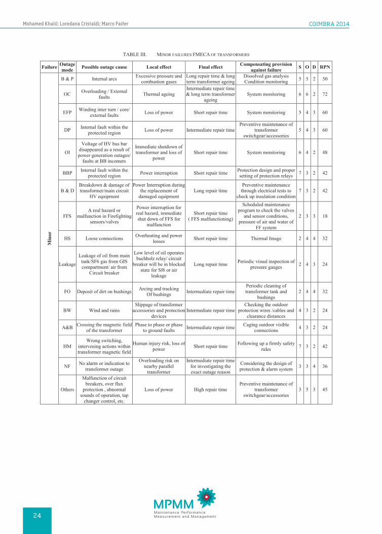
TABLE III. MINOR FAILURES FMECA OF TRANSFORMERS
Failure Outage mode Possible outage cause Local effect Final effect Compensating provision
against failure S O D RPN
Min
or
B & P Internal arcs Excessive pressure and combustion gases
Long repair time & long term transformer ageing
Dissolved gas analysis Condition monitoring 5 5 2 50
OC Overloading / External faults Thermal ageing
Intermediate repair time & long term transformer
ageing System monitoring 6 6 2 72
EFP Winding inter turn / core/ external faults Loss of power Short repair time System monitoring 5 4 3 60
DP Internal fault within the protected region Loss of power Intermediate repair time
Preventive maintenance of transformer
switchgear/accessories 5 4 3 60
OI
Voltage of HV bus bar disappeared as a result of power generation outages/
faults at BB incomers
Immediate shutdown of transformer and loss of
power Short repair time System monitoring 6 4 2 48
BBP Internal fault within the protected region Power interruption Short repair time Protection design and proper
setting of protection relays 7 3 2 42
B & D Breakdown & damage of transformer/main circuit
HV equipment
Power Interruption during the replacement of
damaged equipment Long repair time
Preventive maintenance through electrical tests to
check up insulation condition 7 3 2 42
FFS A real hazard or
malfunction in Firefighting sensors/valves
Power interruption for real hazard, immediate shut down of FFS for
malfunction
Short repair time ( FFS malfunctioning)
Scheduled maintenance program to check the valves
and sensor conditions, pressure of air and water of
FF system
2 3 3 18
HS Loose connections Overheating and power losses Short repair time Thermal Image 2 4 4 32
Leakage
Leakage of oil from main tank/SF6 gas from GIS compartment/ air from
Circuit breaker
Low level of oil operates buchholz relay/ circuit
breaker will be in blocked state for Sf6 or air
leakage
Long repair time Periodic visual inspection of pressure gauges 2 4 3 24
FO Deposit of dirt on bushings Arcing and tracking Of bushings Intermediate repair time
Periodic cleaning of transformer tank and
bushings 2 4 4 32
BW Wind and rains Slippage of transformer
accessories and protection devices
Intermediate repair time Checking the outdoor
protection wires /cables and clearance distances
4 3 2 24
A&B Crossing the magnetic field of the transformer
Phase to phase or phase to ground faults Intermediate repair time Caging outdoor visible
connections 4 3 2 24
HM Wrong switching,
intervening actions within transformer magnetic field
Human injury risk, loss of power Short repair time Following up a firmly safety
rules 7 3 2 42
NF No alarm or indication to transformer outage
Overloading risk on nearby parallel
transformer
Intermediate repair time for investigating the exact outage reason
Considering the design of protection & alarm system 3 3 4 36
Others
Malfunction of circuit breakers, over flux
protection , abnormal sounds of operation, tap
changer control, etc.
Loss of power High repair time Preventive maintenance of
transformer switchgear/accessories
3 5 3 45
COIMBRA 2014
MPMM Maintenance Performance Measurement and Management24
Mohamed Khalil; Loredana Cristaldi; Marco Faifer

TABLE IV. MAJOR FAILURES FMECA OF TRANSFORMERS
Failure Outage mode
Possible outage cause Local effect Final effect Compensating provision
against failure S O D RPN
Maj
or
On-load tap changer
Wearing out of selector contact, loose base, loose
spring, low insulation of oil
Arcs and partial discharges inside tap. Overheating
and excessive pressure
Replacement of tap changer and loss of power
Preventive maintenance based on regular periods or
number of tap changer operations.
Online oil filtration.
7 4 7 196
Winding
Continuous Overloading,
moisture contents, sludge,
oxidation
Thermal and mechanical ageing of winding.
Incapability to stand future short
circuits
Transformer ageing, and
replacement of transformer
Mechanical and Electrical condition assessment
(SFRA, DC resistance of winding, turns ratio,
Meggar)
9 2 9 162
Core
Rust deposits, excessive heating or burning of the
laminations insulation
Hot spot, high losses as a result of eddy current
and flux distortion
Transformer ageing.
Replacement of transformer
Condition monitoring through Dissolved gas analysis, oil and furan
analysis.
9 2 9 162
Oil-Filled Bushings
Moisture from leaky gaskets. Gas bubbles
from prolonged exposure to
extreme electrical,
mechanical and environmental
conditions.
Conducting tracks that can
short out one or more layers of the bushing.
Bushing/ gasket
replacement
Thermal image and bushing tan delta,
capacitance monitoring.
Periodic inspection of oil level of the busing window
6 2 7 84
Tank
Tank rupture as a result of severe short circuit and malfunction in
protection system
Transformer replacement Loss of power Regular testing of
protection systems 9 2 3 54
Insulation
deterioration
Oxidation, high acidity, low
breakdown of oil, moisture of
windings paper
High arcing, corona, and
partial discharge
Oil filtration / oil replacement
in site, or reprocessing of
insulation condition in
factory
Dissolved gas analysis monitoring, Furan test, tan delta of oil, and chemical
analysis of oil characteristics
8 4 8 256
IV. CONCLUSIONS The aim of presenting a FMECA on utility transformers is to
provide power utilities a guide of feasible hazards that could interrupt transformers operation and result in financial losses. FMECA risk priority number depends on many factors and varies according to the operating and environmental condition of power utilities. We tried to generalize the severity, occurrence and detection of the 220 kV transformer failures for a better performance in the transmission network.
REFERENCES [1] IEEE Guide for Reporting Failure Data for Power Transformers and
Shunt Reactors on Electric Utility Power Systems. 1986. [2] An international survey on failures in large power transformers in service,
Final Report of Working Group 05 of Study Committee 12, Electra, 88, May 1983.
[3] MSA Minhas, JP Reynders, and PJ de klerk, "Failure in power system transformers and appropriate monitoring techniques," presented at the
11th International Symposium on High Voltage Engineering, London, U.K., 1999
[4] J.N. Jagers, J. Khosa, P.J. De Klerk, and C.T. Gaunt,” Transformer Reliability and Condition Assessment in a South African Utility, “presented in XV International Symposium on High Voltage Engineering, Ljubljana, Slovenia, August 2007.
[5] Dietermann T, Balzer G, Neumann C. The development in electricity exchanges and their impact on the German transmission system. In: Proceedings of the power tech, Lausanne, Switzerland; 2007. p. 12–6
[6] European Network of Transmission System of Electricity, TEN-YEAR NETWORK DEVELOPMENT PLAN 2010-2020, final report 2010. Available on www.entsoe.eu
[7] J. Jansen, “EHV lines in the Federal Republic of Germany,” IEEE Spectrum, 7 (4) (2009), pp. 33–40
[8] Mateescu, E.; Marginean, D.; Florea, G.; Gal, S.I.A.; Matea, C., "Reconductoring using HTLS conductors. Case study for a 220 kV double circuit transmission LINE in Romania," Transmission and Distribution Construction, Operation and Live-Line Maintenance (ESMO), 2011 IEEE PES 12th International Conference, pp.1-7, May 2011.
[9] M. Abdelfatah, M. EL-Shimy, and H. M. Ismail, “Reliability and maintainability analysis of medium voltage transformers in Egypt,” in 8th
25
FMECA Analysis for the Assessing of Maintenance Activity for Power Transformers
ISBN 978-972-8954-42-0 | http://dx.doi.org/10.14195/978-972-8954-42-0_4

International Conference on Electrical Engineering ICEENG-8, Cairo, Egypt, 2012.
[10] IEC-60182, Analysis techniques for system reliability- Procedure for failure mode and effects analysis (FMEA), 2006.
[11] MIL-STD-1629A, Procedures for Performing a Failure Mode, Effects and Criticality Analysis, Nov. 1980.
[12] Department of the Army, TM 5-698-4, Failure Modes, Effects and Criticality Analyses (FMECA) for Command, Control, Communications, Computer, Intelligence, Surveillance, and Reconnaissance (C4ISR) Facilities, 29 September 2006.
[13] IEEE guide for general principles of reliability analysis of nuclear power generating station protection systems, ANSI/IEEE std. 352, 1987.
[14] Sen, P.K.; Sarunpong Pansuwan, "Overloading and loss-of-life assessment guidelines of oil-cooled transformers," Rural Electric Power Conference, 2001, pp.B4/1-B4/8, 2001.
[15] IEEE Guide for the Interpretation of Gases Generated in Oil-Immersed Transformers," IEEE Std. C57.104-2008 (Revision of IEEE Std. C57.104-1991), pp.1-36, 2009.
[16] IEC-60354, loading guide for oil-immersed power transformers, 2nd edition, 1991.
[17] Arshad, M.; Islam, S.M., "Significance of cellulose power transformer condition assessment," Dielectrics and Electrical Insulation, vol.18, no.5, pp.1591-1598, October 2011.
[18] Jauch, E.T., "How Tapchanger Controls Contribute to Premature Transformer Failures," Power Engineering Society General Meeting, pp.1-5, June 2007.
[19] R. Jongen, Peter Morshuis, E. Gulski, and J. Smit, “Statistical analysis of power transformer component life time, ” in Proc. 8th International Power Eng. Conf. (IPEC 2007), Singapore, 2007, pp. 1273-1277.
[20] Thanapong Suwanasri, Ekkachai Chaidee, and Cattareeya Adsoongnoen, "Failure statistics and power transformer condition evaluation by dissolved gas analysis technique," in international Conference on Condition Monitoring and Diagnosis, Beijing, China, 2008.
[21] M. Abdelfatah, M. EL-Shimy, and H. M. Ismail, “Outage data analysis of utility power transformers based on outage reports during 2002-2009,” in International Journal of Electrical Power & Energy Systems, Volume 47, pp. 41-51, May 2013.
[22] M. EL-Shimy, M. Abdelfatah, and H. M. Ismail, “Reliability, Availability, and Maintainability (RAM) Analysis of Utility Power Transformers,” in ELEKTRIKA- UTM Journal of Electrical Engineering, Vol. 14, No 1 (2012).
[23] M. Abdelfatah, M. EL-Shimy, and H. M. Ismail, “Performance analysis of protective devices for power transformers in Egypt,” in 8th International Conference on Electrical Engineering ICEENG-8, Cairo, Egypt, 2012.
[24] Renaud, F., "220 kV gas-insulated transmission line-Palexpo Geneva Switzerland," Power Engineering Society General Meeting, 2003, IEEE , vol.4, no., pp.,2479 Vol. 4, 13-17 July 2003.
[25] Borucki, S.; Boczar, T.; Fracz, P.; Zmarzly, D., "Diagnostics of power transformers cores using a modified vibroacoustic method," Electrical Insulation (ISEI), Conference Record of the 2012 IEEE International Symposium, pp.179-183, 10-13 June 2012
COIMBRA 2014
MPMM Maintenance Performance Measurement and Management26
Mohamed Khalil; Loredana Cristaldi; Marco Faifer