e s o a d ap tive o p tics f acility s o a d ap tive o p tics f acility r. arsenault a, p.-y. madec...
TRANSCRIPT

ESO Adaptive Optics Facility R. Arsenault a, P.-Y. Madec a, N. Hubin a, J. Paufique a, S. Stroebele a, C. Soenke a, R. Donaldson a, E. Fedrigo a, S. Oberti a, S. Tordo a, M. Downing a, M. Kiekebusch a, R. Conzelmann a, M. Duchateau a,
A. Jost a, W. Hackenberg a, D. Bonaccini Caliaa, B. Delabrea, R. Stuikd, R. Biasib, D. Gallienic, P. Lazzarinic, M. Lelouarna, A. Glindemana
aEuropean Southern Observatory, Karl-Schwarzschild-str.2, 85748 Garching bei Muenchen, Germany
bMicroGate S.r.l., Via Stradivari 4, 39100 Bolzano, Italy cADS International Srl, via Roma 87, 23868 Valmadrera (Lc), Italy
dUniversity of Leiden, P.O. Box 9513, 2300 RA Leiden, The Netherlands
ABSTRACT
ESO has initiated in June 2004 a concept of Adaptive Optics Facility. One unit 8m telescope of the VLT is upgraded with a 1.1 m convex Deformable Secondary Mirror and an optimized instrument park. The AO modules GALACSI and GRAAL will provide GLAO and LTAO corrections forHawk-I and MUSE. A natural guide star mode is provided for commissioning and maintenance at the telescope. The facility is completed by a Laser Guide Star Facility launching 4 LGS from the telescope centerpiece used for the GLAO and LTAO wavefront sensing. A sophisticated test bench called ASSIST is being designed to allow an extensive testing and characterization phase of the DSM and its AO modules in Europe. Most sub-projects have entered the final design phase and the DSM has entered Manufacturing phase. First light is planned in the course of 2012 and the commissioning phases should be completed by 2013.
Keywords: GLAO, LTAO, Large Deformable Mirror, ELT Pathfinder, Adaptive Telescope,
1. INTRODUCTION 1.1 Project Description
The Adaptive Optics Facility (AOF) is an integrated project to upgrade one of the 8m VLT telescope units into an adaptive telescope. The main changes are the replacement of the existing Dornier M2-Unit by a new one hosting a Deformable Secondary Mirror (DSM) and the addition of 4 launch telescopes on the centerpiece to launch 4 sodium (Na) beacons. The telescope optical train contains thus an active (M1) and an adaptive (M2) mirror. All focii (2 Nasmyth + Cassegrain + Coude) can be adaptively corrected if wavefront sensors are implemented at the corresponding locations. Two Adaptive Optics (AO) modules are being developed on the two opposite Nasmyth focii to take advantage of this new turbulence correction capability of the telescope.
The two AO modules are called GRAAL and GALACSI and will serve the instruments Hawk-I and MUSE. Hawk-I is a large field IR imager that has been built in-house (ESO) and commissioned. GRAAL will improve the efficiency of Hawk-I by increasing the energy concentration per pixel (Ground Layer Adaptive Optics mode: GLAO). MUSE is an integral field spectrometer developed by a European consortium led by the CRAL (Lyon, France). Two AO correction modes are proposed for MUSE: a GLAO mode for the so-called Wide Field Mode and a Laser Tomography Adaptive Optics (LTAO) correction for the so-called: Narrow Field Mode. The latter is a very challenging mode aiming at reaching a 5% (10% goal) Strehl ratio @ 650 nm, a performance equivalent to typical planet finder systems in H or K band. The science cases for the AOF have been defined from the upgraded mode of Hawk-I and MUSE science cases.
This AOF configuration, challenges and technical problems are very similar to extremely large telescopes being developed nowadays. This is the reason why the motivation to realize the AOF at ESO is also, apart from the scientific capability, to play a pathfinder role for the EELT.

1.2 EELT Pathfinder
The EELT pathfinder role is two-fold: first to tackle problems now and identify technical design solutions and second to enable technologies required for the EELT. The following common issues have already been identified:
High order AO at diffraction limit (tight error budget) - Operate this new multi-deformable mirror (active and adaptive) Telescope - Develop, operate & master LTAO & GLAO systems - Master AO interaction matrix calibration - Manage multiple interlaced control loops & offloading processes - Extensive DSM testing procedures before commissioning - Manage efficient commissioning of such complex system - Promote Development of robust high power Lasers - Promote Development of fast read-out low RON CCD’s - Develop Large computing power Real Time Computer (SPARTA).
2. SYSTEMS TECHNICAL DESCRIPTION 2.1 GRAAL: The Adaptive Optics Module for Hawk-I
The GRound layer Adaptive optics system Assisted by Lasers (GRAAL) will improve the quality of HAWK-I images reducing by 12 % in Y and 21% in Ks band the diameter collecting 50% of the energy for 1 arcsec visible seeing conditions over the entire 7.5 arcmin Field Of View. Performance has also been expressed in gain of energy per 0.1” pixel and it reaches a factor of 2 in K-band. The system will use the Deformable Secondary Mirror conjugated to the ground. The DSM will have enough stroke and degrees of freedom to correct for the atmospheric seeing (up to 2” seeing) including the atmospheric tip-tilt and for VLT field stabilization.
Four Sodium Laser Guide Stars emitted from four 30 cm laser projectors located on the VLT centerpiece will be sensed by four 40x40 Wave-Front Sensors. A visible tip-tilt sensor monitors the atmospheric and telescope tip-tilt. To avoid obscuration of the HAWK-I FOV the visible NGS will be acquired outside the HAWK-I FOV between 6.7 and 7.7 arcmin from the optical axis.
The commissioning instrument for the DSM is a sub-module of GRAAL labeled Maintenance & Commissioning Mode (MCM) and will be implemented inside the AO module. One 40×40 SH retractable WFS and its associated optical system will be mounted on the AO structure and will use NGS on-axis for wavefront sensing.
The AO module consists of the following units (see Figure 1):
Figure 1: Mechanical design of GRAAL. Left view from Hawk-I side, Right view from Nasmyth flange side.
! Four LGS WFSs
! One visible TT sensor outside of the HAWK-I FOV ! One NGS WFS for the Deformable Secondary Mirror commissioning and maintenance ! One focal elongator to place in front of HAWK-I camera to verify the DSM performance ! One calibration unit for the four LGS WFSs
The LGS WFSs This unit consists of 4 identical systems. Each system is composed of
! One small pickup mirror placed with a fixed arm at 5.5’ from the optical axis on the Nasmyth focal plane. ! One trombone allowing focusing of the LGS ! One re-imaging objective composed of two lenses ! One 40x40 micro lenses array ! One 240×240 L3 CCD & NGC controller
Each pickup mirror redirects the LGS light to a classical Shack-Hartmann wavefront sensor. The system accepts focus variations from 80 to 180 km.
Visible Tip-Tilt sensor GRAAL will make use of a visible NGS TT sensor. The Natural Guide Star is then collected before the Nasmyth focal plane outside the HAWK-I FOV. A pick-up mirror selects the NGS inside a FOV ring of internal radius 6.7’ and external radius 7.7’. This system is composed of:
! One pickup mirror with at least 50 arcsec FOV ! One re-imaging objective ! One 240×240 L3 CCD
Commissioning and maintenance WFS for the Deformable Secondary Mirror The DSM will be first used with GRAAL. A specific NGS WFS is foreseen inside GRAAL for the DSM commissioning and maintenance. This system is composed of:
! A dichroic to separate the visible light (WFS path) and the IR light (HAWK-I) ! A focal elongator to reduce the pixel size on the HAWK-I camera down to 0.016 arcsec/pixel and therefore to increase the resolution, on a 10’’FOV; this elongator is composed of two mirrors and one field lens ! a divergent lens to deport the WFS entrance focus ! a re-imaging objective ! A 40×40 micro lenses array ! One 240×240 L3 CCD
2.2 GALACSI: The Adaptive Optics Module for MUSE
GALACSI is part of the AOF, and associated with the DSM and the 4LGSF it defines an AO system developed to increase the performance of the MUSE instrument, a panoramic integral-field spectrograph built by a consortium led by CRAL. The system GALACSI combined with the MUSE instrument is dubbed MUSE facility.
Two AO observing modes are requested by the MUSE science cases: ! A one arc-minute Wide Field Mode. GALACSI is requested to increase the ensquared energy over the 1 arc-
minute FoV of the MUSE spectrograph. GALACSI will use 4 LGSs to probe atmospheric turbulence and the WFS signals will be used to correct for the turbulent ground layer. In addition, one visible Natural Guide Star is used to correct for the remaining atmospheric tip-tilt.
! A 7.5 arcsec field of view Narrow Field Mode. GALACSI is requested to provide at least 5% Strehl Ratio at 650nm and to deliver diffraction limited images over the narrow FoV of the MUSE spectrograph. GALACSI will use 4 LGSs to perform tomography of the turbulence and the WFS signals will be used to correct for the turbulence in the centre of the field. In addition, one IR Natural Guide Star is used to correct for the remaining atmospheric tip-tilt, defocus and astigmatisms.
GALACSI will be installed at Nasmyth – B Focus of UT4.
In its Wide Field Mode the laser guide stars are located at 64” off-axis in a square configuration. In its Narrow Field Mode the laser guide stars are located at 10” off-axis in a square geometry. Visible Tip-Tilt Natural Guide star sensor for the Wide Field Mode:this Tip-Tilt NGS is expected to have a limiting magnitude around Mv~17.5. Natural Tip-Tilt star will be acquired within a 3.4’ technical FOV but outside the 1’ square scientific FOV of MUSE to not reduce the flux within the scientific FOV. An IR on-axis Low Order Sensor (using natural guide star) will be used for the 7.5” Narrow Field Mode. It is mounted inside the MUSE fore optics to correct for the atmospheric tip-tilt, and residual defocus and astigmatisms and to minimize differential image motions between GALACSI and MUSE. Light separation will be done with a VIS/IR dichroic located inside the MUSE fore optics. A 85” FOV commissioning camera will be used to verify the GALACSI performance in WFM and NFM. This camera can be also focused to the LGSs and be used for their acquisition. This commissioning camera will be located after the Nasmyth focal plane. One GALACSI calibration unit is implemented. It will provide sources at the LGSs positions and for NGSs. Its sources will be re-imaged to the Nasmyth focal plane and folded by a mirror. It allows the calibration of the field selector of the WFSs and most instrumental functions.
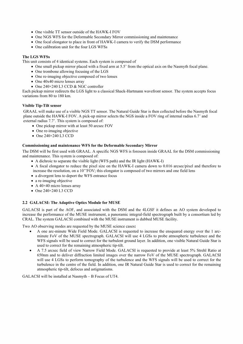
2.2.1 Mechanical implementation The GALACSI main structure is shown in Figure 2. All optical components and mechanical systems are integrated in one compact structure attached to the Nasmyth rotator. The GALACSI structure carries also all electronics requiring a short cable length to the controlled system (e.g. detector read out electronics). GALACSI will use as well 1 standard cabinets on the Nasmyth platform for Cryostat and Peltier control (detectors), alarms, CAN bus controller and one cabinet on the Azimuth platform to host the NGCs back end electronics and the SPARTA RTC. The cables (pipes and fibers) required for the connection between GALACSI and its cabinets on the Platform and to the SCP are guided by a standard cable chain. GALACSI will co-rotate to the telescope altitude axis (operational range: 0-60˚, functional range: 0-92˚). This reduces the length of the cable guide compared to a co-rotation to the field and the volume occupied. The mass (part attached to the rotator) is below 1000kg.
Figure 2 : The optical layout (left) and 3D mechanical model (right) of GALACSI.
The IR Low Order Sensor is a major sub-assembly that is mounted after MUSE fore-optics. The IRLOS is a 4 sub apertures (2 by 2) Shack Hartman WFS with a HAWAII -1RG detector read by a 4 channel IR-NGC system. At the entrance a ND wheel allows to attenuate bright sources and to close the sub assembly. The MUSE fore optics forms a pupil inside the assembly. At this location we place tip tilt mirror used as field selector. The IRLOS will offer 2 plate scales, 60 mas /pixel and 200mas/pixel for sufficient field to use extended sources. The IRLOS will be operated at a frame rate of 250 Hz. The maximum window size which can be read at real time is 22by22 pixels per subaperture. This limits the field of view to 1.3” and 4.4”.

2.3 DSM
The Deformable Secondary Mirror (DSM) has been subcontracted to a consortium of Italian companies composed of MicroGate, ADS Intl. and the Arcetri Observatory. The project has successfully passed the final design stage (Dec. ’07) and the manufacturing has started. Delivery to ESO is expected in the 3rd quarter of 2011.
The DSM design is similar to the MMT and LBT secondary deformable mirrors but having benefited from a successive generation improvements. It consists of a sub-assembly of a cold plate, a reference body and a thin shell providing the reflecting surface. Magnets are glued on the shell back face in front of voice coil actuators inserted in the reference body. The reference body front face and shell back face are concentric and a fixed gap insures the proper shape of the shell front surface (to be refined by a “flattening vector” to take into account figure imperfections of reference body and thin shell). Capacitive sensors made of ring of metal deposited on the reference body and thin shell back face opposite to each other, are co-located with the actuators; control of the capacitance with adequate electronic insures a feedback on the local gap shell-reference body which is used by the local electronic control loop to maintain an appropriate force on each actuator and to adjust the gap to the desired value. The actuators themselves are held by the coldplate which is actively cooled with a fluid circulation allowing active cooling of the actuators. The DSM is hosted in a hub that has identical interfaces to the nominal Dornier M2-Units of the VLT. It also implements the same functionalities for positioning of the M2 optical surface: focusing, centering and chopping. Note that a Hexapod is used to apply focusing and centering. The hexapod also allows change of focal station from Nasmyth to Cassegrain by a displacement along the optical axis of M2 of 31 mm.
Figure 3: Rendering of the complete new M2-Unit of the VLT hosting the 1170 actuators Deformable Secondary Mirror.
The so-called centering correction is used to rotate M2 around its center of curvature. This has the effect of correcting decentering coma induced by flexure of the telescope struts, without changing the pointing of the telescope. Note that in
adaptive correction mode this motion will be used to recenter the pupil (M2) on the wavefront sensors (WFS); coma aberration will be corrected by M2 and then offloaded to M1. Chopping is produced by the thin shell tilt correction and is reduced compared to the Dornier M2-Unit. The total stroke available for tilt is of 6 arcsec on sky. Note however, that neither MUSE nor Hawk-I will make use of chopping (former is visible instrument and latter will use dithering). Only the VLTI will require chopping but a smaller stroke is acceptable given the smaller field of view (~1”) of VLTI instruments. Note that if a Cassegrain AO module would be developed and requiring chopping, it will be implemented using internal chopping, which is also the solution envisioned for EELT.
Figure 4: Representation of the DSM reference body. At the time of this writing the contractors (Microgate-ADS)
are procuring the optical components this is the reference body and the engineering grade shell. The science shell will be procured later to insure a best possible match with the reference body, as built, radius of curvature. The thin shell is a critical components; it is a 1120mm diameter Zerodur optics, 2mm thick and with an aspheric convex optical surface. The reference body is also a quite delicate optical component due to the extricate lightweighting scheme (see Figure 4).
2.4 Four Laser Guide Star Facility (4LGSF)
The Four Laser Guide Star Facility (4LGSF) will produce four Sodium (Na) laser beacons for the AO modules GRAAL and GALACSI. It consists of 4 lasers feeding 4 separate launch telescopes mounted on the VLT centerpiece. The selection of the fourth Unit Telescope of the VLT for the AO Facility allows the common use of the Aircraft Avoidance System and existing Laser Clean Room. The project is still in preliminary design stage but is about (June’08) to issue a call for tender for the procurement of the laser sources.
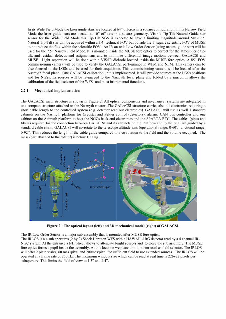
The base design is illustrated in Figure 5. Compact laser sources are hosted in cabinets mounted on the 8m telescope centerpiece; one cabinet for a laser source and frequency conversion unit, the other for control electronics. In this configuration the launch telescope is a few meters (1-2m) away and the beam transport can be accomplished by a simple mirror relay or a fiber if part of the laser source design. On the four corners of the center piece launch telescopes are coupled to long light baffles to minimize scattered light in the dome area.
Figure 5: Mechanical layout of a VLT 8m telescope showing in green and red the cabinet space reserved for laser and its electronic implementation; grayed out
volumes represent handling safety zones. The 4 large tubes on the corner represent
the launch telescopes and their baffle tubes. A 30 cm launch telescope useful aperture has been selected and found adequate to produce the spot size required for wavefront sensing. At this stage trade-off analysis is underway to select the best launch telescope design. Solutions using refractive or reflective design are considered. The required field of view is ±6 arcmin and two solutions are envisioned to accomplish this function: a small tip-tilt mirror feeding the beam at the entrance focal plane of the launch telescope (launch telescope field of view is thus 6 arcmin in diameter) or an on-axis telescope design that is pointed by an appropriate mount.
Depending on the laser spectral purity, the level of output power requested is not the same. In all cases, it has to be noted that the driver for the output power is the NFM of GALACSI. It requires to get 5 106 photons/m2/s at the Nasmyth Focus of the UT, for a Na abundance of 4 1013 m-2. Taking into account the UT4 and the Launch Telescope throughput as well as the atmospheric transmission, this number corresponds to an output laser power of 25 W for a single-line laser. The requested output power will increase with the laser linewidth.
Given the challenges for the laser design and the few potential suppliers, the interfaces have been simplified to accommodate several different types of laser. Compact lasers would be mounted on the Telescope centerpiece in insulated electronic cabinets (baseline design). This solution has the advantage of simplifying beam transport to the launch telescope which would be located less than a few meters away. In case of bulky lasers mounted on large optical table, they would be installed into the Laser Clean Room (under the Nasmyth platform). This is not compatible with the baseline design because a complex mirror relay system would need to be implemented. Efforts are spent in this direction
to better understand the consequences (design, manufacturing time and cost) and be prepared in case the only available lasers are bulky.
If the call for tender results in the selection of a compact laser, the preliminary design review could be held in late 2008/ early 2009. In the opposite case, a more complex design must be completed including a mirror relay from the Laser Clean Room to the launch telescopes. Budget and schedule for the AOF will have to be re-assessed. This constitutes at this stage the most serious risk for the project.
2.5 ASSIST
ASSIST is an effort led by NOVA (The Netherland). It is considered as the corner stone of the assembly, integration & test phase in Europe, allowing full characterization and optimization of the AO modules plus the DSM. This appears to the designers as a fundamental pre-requisite to ease and smooth out the commissioning phases at the telescope in Paranal (Chile).
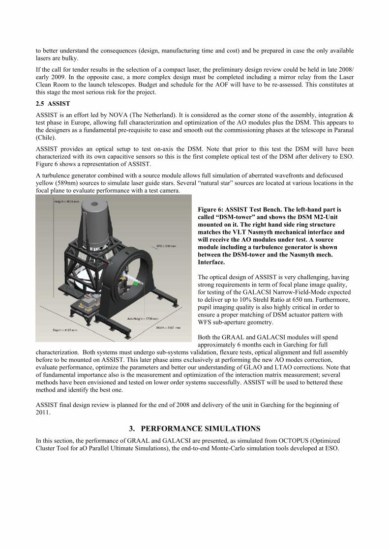
ASSIST provides an optical setup to test on-axis the DSM. Note that prior to this test the DSM will have been characterized with its own capacitive sensors so this is the first complete optical test of the DSM after delivery to ESO. Figure 6 shows a representation of ASSIST.
A turbulence generator combined with a source module allows full simulation of aberrated wavefronts and defocused yellow (589nm) sources to simulate laser guide stars. Several “natural star” sources are located at various locations in the focal plane to evaluate performance with a test camera.
Figure 6: ASSIST Test Bench. The left-hand part is called “DSM-tower” and shows the DSM M2-Unit mounted on it. The right hand side ring structure matches the VLT Nasmyth mechanical interface and will receive the AO modules under test. A source module including a turbulence generator is shown between the DSM-tower and the Nasmyth mech. Interface. The optical design of ASSIST is very challenging, having strong requirements in term of focal plane image quality, for testing of the GALACSI Narrow-Field-Mode expected to deliver up to 10% Strehl Ratio at 650 nm. Furthermore, pupil imaging quality is also highly critical in order to ensure a proper matching of DSM actuator pattern with WFS sub-aperture geometry. Both the GRAAL and GALACSI modules will spend approximately 6 months each in Garching for full
characterization. Both systems must undergo sub-systems validation, flexure tests, optical alignment and full assembly before to be mounted on ASSIST. This later phase aims exclusively at performing the new AO modes correction, evaluate performance, optimize the parameters and better our understanding of GLAO and LTAO corrections. Note that of fundamental importance also is the measurement and optimization of the interaction matrix measurement; several methods have been envisioned and tested on lower order systems successfully. ASSIST will be used to bettered these method and identify the best one. ASSIST final design review is planned for the end of 2008 and delivery of the unit in Garching for the beginning of 2011.
3. PERFORMANCE SIMULATIONS In this section, the performance of GRAAL and GALACSI are presented, as simulated from OCTOPUS (Optimized Cluster Tool for aO Parallel Ultimate Simulations), the end-to-end Monte-Carlo simulation tools developed at ESO.
The main modules of OCTOPUS are described [1]. Then, section 3.1 recalls the main relevant parameters considered for the simulation, as for example the Cn
2 profile, wind profile, the NGS and LGS brightness and the features of the deformable mirror (DSM) and the wavefront sensors (Shack-Hartmann based on a zero read-out-noise L3CCD detector). Section 3.2 will present the performance of GRAAL as simulated from OCTOPUS and considering its own error budget, while GALACSI performance will be given in sections 3.3 and 3.4.
3.1 Input parameters The input parameters considered evaluating the performance of GRAAL and GALACSI are described in the following sections.
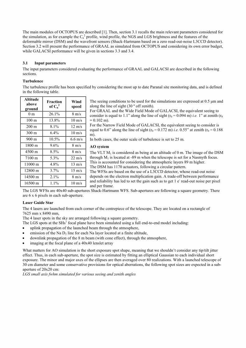
Turbulence The turbulence profile has been specified by considering the most up to date Paranal site monitoring data, and is defined in the following table.
The seeing conditions to be used for the simulations are expressed at 0.5 µm and along the line of sight (30 º off zenith). For GRAAL and the Wide Field Mode of GALACSI, the equivalent seeing to consider is equal to 1.1” along the line of sight (r0 = 0.094 m) i.e. 1” at zenith (r0 = 0.102 m). For the Narrow Field Mode of GALACSI, the equivalent seeing to consider is equal to 0.6” along the line of sight (r0 = 0.172 m) i.e. 0.55” at zenith (r0 = 0.188 m). In both cases, the outer scale of turbulence is set to 25 m.
AO system The VLT M1 is considered as being at an altitude of 0 m. The image of the DSM through M1 is located at -89 m when the telescope is set for a Nasmyth focus. This is accounted for considering the atmospheric layers 89 m higher. The DSM has 1170 actuators, following a circular pattern. The WFSs are based on the use of a L3CCD detector, whose read-out noise depends on the electron multiplication gain. A trade-off between performance and reliability has led to set the gain such as to get 1 e- read-out noise per pixel and per frame.
The LGS WFSs are 40x40 sub-apertures Shack-Hartmann WFS. Sub-apertures are following a square geometry. There are 6 x 6 pixels in each sub-aperture.
Laser Guide Star The 4 lasers are launched from each corner of the centrepiece of the telescope. They are located on a rectangle of 7625 mm x 8490 mm, The 4 laser spots in the sky are arranged following a square geometry. The LGS spots at the SHs’ focal plane have been simulated using a full end-to-end model including: ! uplink propagation of the launched beam through the atmosphere, ! emission of the Na D2 line for each Na layer located at a finite altitude, ! downlink propagation of the 8 m beam (with cone effect), through the atmosphere, ! imaging at the focal plane of a 40x40 lenslet array
What matters for AO simulation is the short exposure spot shape, meaning that we shouldn’t consider any tip/tilt jitter effect. Thus, in each sub-aperture, the spot size is estimated by fitting an elliptical Gaussian to each individual short exposure. The minor and major axes of the ellipses are then averaged over 80 realizations. With a launched telescope of 30 cm diameter and some conservative provisions for optical aberrations, the following spot sizes are expected in a sub-aperture of 20x20 cm: LGS small axis fwhm simulated for various seeing and zenith angles
Altitude above
ground
Fraction of Cn
2 Wind speed
0 m 26.1% 8 m/s 100 m 13.8% 10 m/s 200 m 8.1% 12 m/s 300 m 6.4% 10 m/s 900 m 10.5% 6.6 m/s
1800 m 9.6% 8 m/s 4500 m 8.5% 8 m/s 7100 m 5.3% 22 m/s 11000 m 4.8% 13 m/s 12800 m 3.7% 15 m/s 14500 m 2.1% 8 m/s 16500 m 1.1% 10 m/s

Using the previous table, the LGS spot size (small axis) is defined as follows: ! 1.3” for GRAAL and GALACSI WFM (seeing of 1.1” along the line of sight). ! 1” for GALACSI NFM (seeing of 0.6” along the line of sight).
The sodium profile is assumed to be Gaussian with a FWHM of 7 km. This way, the elongation grows from one edge of the pupil till the other to reach, in a sub-aperture located 8 m far from the launch telescope, a long axis FWHM of: ! 2.05” for GRAAL and GALACSI WFM.
! 1.85” for GALACSI NFM.
The elongation value given above includes the intrinsic LGS size and thus depends on the seeing value.
Laser Guide Star jitter Due to fundamental limitation, it is not possible to compensate for the jitter of the LGS as seen from the focal plane of the sub-apertures. This jitter is mainly due to the effect of the atmosphere on the laser beam on its up-link path. The main effect of this jitter is to introduce measurement errors due to the finite FoV of the sub-apertures. To reduce this effect, a local control loop is used to stabilize the image of the LGS. Two alternative solutions are investigated to reduce this jitter. In case of GRAAL, the baseline is to use fast steering mirrors located at the level of the LGS Launch Telescopes while for GALACSI the baseline is to use the same kind of corrective devices but located in the LGS WFS path. In both cases, the jitter measurement comes from the LGS WFS themselves. In the case of GRAAL, the laser propagation time introduces a supplementary time lag in the jitter loop depending on the telescope elevation angle. For GALACSI, this time lag does not exist, allowing getting better rejection performance. These two options have been simulated. The residual jitters on one axis (quadratic sum of the two axes) to be considered for each mode are the following conservative values: ! 150 mas rms for GRAAL. ! 80 mas rms for GALACSI WFM. ! 60 mas rms for GALACSI NFM.
Throughput The throughput budget is presented hereafter:
The LGS-mirrors and optics will be optimized for Na-wavelength, so the actual values could be slightly higher, but with those values, a provision for aging/dust is taken.
3.2 GRAAL performance Using OCTOPUS simulation tool, the design of GRAAL has been finalized through trade-offs between performance and robustness. Standardization with GALACSI has also been taken into account, to better deal with maintenance and spare policy. For GRAAL, it is recalled that the tip-tilt is corrected thanks to a dedicated Tip-Tilt Sensor. It is fed by a
NGS whose visible part of the spectrum is used. The detector associated to the TTS is a L3CCD, with the same features as the one used for the LGS WFS. The final design parameters of GRAAL are summarized hereafter: ! LGS positions 5.7 arcmin from the optical axis ! LGS WFS plate scale 0.83”/pixel (5” FoV per sub-aperture) ! LGS WFS sampling frequency 500 Hz ! LGS flux 2.5 106 photons/m2/s at Nasmyth focus ! TT star position 13.2 to 15.2 arcmin from the optical axis ! Visible TTS plate scale 0.25”/pixel ! Visible TTS sampling frequency 250 Hz
Seeing (in”) / zenith angle (degrees)
0 30
0.6 1.01 1.06 1 1.24 1.32
1.5 1.58 1.68
Component Efficiency (LGS: 589 nm)
Atmospheric transmission (1.15 airmass) 0.91 VLT 0.68
LGS path optics 0.72 Lenslet array 0.8
CCD QE 0.8 Total LGS path throughput
Without VLT and atmosphere 0.46 With VLT and atmosphere 0.28

! TT star limited magnitude R=14.5 ! Number of controlled modes 300
The metrics used to evaluate the performance of GRAAL are both the gain in the 50% encircled energy diameter and the gain in energy encircled in 0.1”. The reference wavelength is 2.2 "m. Thanks to OCTOPUS the analysis of these parameters has shown that, as expected for a GLAO system, they are almost insensitive to everything except the seeing and the Cn
2 profile. The final performance is given in the two following figures, both obtained in K-band. In both cases the gain in 50% EE diameter and the gain in the EE in 0.1” are plotted vs the position of the observed object in the scientific field. Both results the average performance and the uniformity across the FoV are of value. The mean value of the gain in 50% EE diameter is 1.24 ± 3 % rms. For the gain in the energy in a 0.1’’, the mean value is 1.73. These values include the GRAAL global error budget. These performance fit with the Science cases as defined for GRAAL associated with HAWK-I.
Figure 7: Gain in the size of 50% EE (left) and gain in the energy in 100 mas (right) as a function of position in the field, in K-band.
3.3 GALACSI WFM performance In the same way as for GRAAL, the design of the WFM of GALACSI has been finalized through trade-offs between performance and robustness. The same standardization constraints have been applied as for GRAAL. For the WFM of GALACSI, the tip-tilt is corrected thanks to a dedicated Tip-Tilt Sensor fed by a NGS whose visible part of the spectrum is used. The detector associated to the TTS is a L3CCD, with the same features as the one used for the LGS WFS.
The final design parameters of the WFM of GALACSI are summarized hereafter: ! LGS positions ! LGS WFS plate scale ! LGS WFS sampling frequency! LGS flux! TT star position ! Visible TTS plate scale ! Visible TTS sampling frequency! TT star limited magnitude ! Number of controlled modes
Figure 8: Gain in the energy in 200 mas as a function of the position in the field.

The metrics used to evaluate the performance of GALACSI is the gain in energy encircled in 0.2” at 0.75 "#m. The analysis of this parameter through simulations has shown that, as expected for a GLAO system, it is almost insensitive to everything except the seeing and the Cn
2 profile. The final performance is given in the following figure, where the gain in the EE in 0.2” is plotted vs the position of the observed object in the scientific field. The GALACSI error budget is not included in this curve. Taking into account the global error budget of the WFM of GALACSI, the mean value of the gain in the energy in a 0.2’ diameter is 1.9 ± 7 % rms. The main contributor to the GALACSI WFM error budget is the transmission loss due to the Na notch filter used to prevent the MUSE scientific field of view from any pollution coming from Na laser (backscattered light). These performances are compliant with the requirements defined for GALACSI associated with the MUSE WFM. 3.4 GALACSI NFM performance Simulation results have been used to finalize the design of the NFM of GALACSI through trade-offs between performance and robustness. Standardization constraints have also been applied as for GRAAL and GALACSI WFM. For the NFM of GALACSI, the tip-tilt is corrected thanks to a dedicated sensor fed by a NGS whose IR part of the spectrum is used. The useful wavelength range considered is in between 0.98 !m and 1.8 "m. The detector associated to this sensor is a Hawaii 1RG, with the following features relevant to GALACSI performance: ! Quantum efficiency 60% ! Read-out noise 15 e-/pixel/frame
The NGS used as a reference for the tip-tilt correction can be either an unresolved or an extended object. In the latter case, the extension of the object is limited to 3 arcsec fwhm, but the final performance will obviously depend on its exact profile. The final design parameters of the NFM of GALACSI are summarized hereafter: ! LGS positions 1 arcmin from the optical axis ! LGS WFS plate scale 0.83”/pixel (5” FoV per sub-aperture) ! LGS WFS sampling frequency 1000 Hz ! LGS flux 5 106 photons/m2/s at Nasmyth focus ! TT star position on-axis ! IR TTS plate scale (unresolved object) 0.066”/pixel (1.3” FoV) ! IR TTS sampling frequency 250 Hz ! TT star limited magnitude (unresolved object) J=15
! Number of controlled modes
The metrics used to evaluate the performance of the NFM of GALACSI is the Strehl Ratio at 0.65 "m. The performance to reach as defined by the GALACSI requirements is 5% with a goal set to 10%. These performances are very challenging, considering a LGS AO system working in the visible. They are the main driver for the design of the AOF.
Figure 9: Strehl Ratio as a function of the position in the field Analyses through simulations have shown that this parameter is very sensitive not only to atmospheric parameters such as the seeing or the coherence time, but also to

system parameters such as the LGS position, the LGS return flux or the IR TT reference star magnitude. The LGS position has been defined to be very close to the optimal one, even if a perfect matching is not possible due to mechanical constraints. The LGS return flux required to meet the global requirements of GALACSI has been defined to cope with seasonal and nightly variations of the Na abundance. As is it now defined, the NFM of GALACSI will always meet its requirement, except during a fraction of the time during the low Na abundance season. This has been deemed worth with respect to the cost increase to get the laser flux required to meet the specifications 100% of the time. Finally, the limited magnitude of the IR TT reference star has been found to be equal to 15: the main limitation comes here from the read-out noise of the IR detector. It has to be noticed that reaching this limited magnitude is only possible thanks to the compensation of the effect of the atmosphere by the AO system. In case of an unresolved IR TT reference star, the final performance of the NFM of GALACSI is given in the following figure, where the Strehl ratio is plotted vs the position of the observed object in the scientific field. The global budget error of the NFM of GALACSI is included in these results. Its total net effect is represented through a corrective Strehl ratio of 64% coming from residual aberration calibration errors and VLT vibrations. The residual calibration errors come from the evolution of the LGS beam foot print on the optical elements due to the evolution of the LGS distance to the telescope with the elevation angle. The differential aberrations introduced during the tracking can only be partly compensated for. The performances as presented in the previous figure are compliant with the requirements defined for GALACSI associated with the MUSE NFM. In case an extended object is considered as TT reference star, the plate scale of the IR TTS will have to be increased to 0.26”/pixel. The FoV will be adjusted to the brightness and the extension of the object, to deal with the read-out noise of the detector. Finally, the limited magnitude is in the range of 10 to 12.5 depending on the profile of the object. This limited magnitude is associated to a final performance of 5% as Strehl ratio. .
4. CONCLUSIONS The Adaptive Optics Facility is a major ESO project aiming at delivering an operational facility to the VLT in Paranal for improved scientific capabilities to the European astronomers while at the same time serving as a pathfinder for the E-ELT. Five major subsystems compose the AOF: a Deformable Secondary Mirror, a 4Laser Guide Star Facility, two AO modules GRAAL & GALACSI delivering GLAO and LTAO correction modes and ASSIST a test bench to qualify the facility in Europe. Most systems have undergone Preliminary Design Phase and the DSM is in manufacturing stage. An intensive Europe characterization and optimization test phase is planned in Europe in 2012 and the whole facility will be commissioned in Paranal during 2013.
REFERENCES
[1] Lelouarn, M., Verinaud, C., Korkiakoski, V., “Simulation of MCAO on (extremely) large telescopes”, Comptes Rendus Physique, Volume 6, Issue 10, 1070-1080 (2005)