Download - Firmesa - Baterias Ps

Engineered With Vision. Built With Care.Power-Sonic has more than 38 years of battery industry experience and today our batteries are sold in more than 70 countries world-wide. Since our inception in 1970, our focus has been the design, manufacture and marketing of rechargeable batteries, specifically:
• Sealed lead-acid (SLA), also called valve regulated lead-acid (VRLA) batteries
• Powersport batteries • Sealed nickel-cadmium (NiCd) and nickel-metal hydride
(NiMH) batteries • NiCd and NiMH configured packs (cell assemblies) • SLA battery chargers • NiCd and NiMH battery chargers
Our products are widely used in an ever broadening range of electronic and industrial applications. Our batteries continue to be used wherever cost effective and reliable DC power is required, be it as the principal power or standby power source.
Our aim is the ongoing improvement of our existing products, coupled with the development of new tailored products, to meet the ever increasing needs for stand alone power. Our advanced engineering techniques and state-of-the-art manufacturing processes ensure that we remain on the cutting edge of battery technology. These skills, coupled with our selection of the finest raw materials, allow us to produce batteries combining superior performance and value.
Providing our customers with reliable, yet economical, products is the cornerstone of our mission.
We’ve Got The Power.™�
Sealed/Maintenance-FreeThe valve regulated, spill-proof construction allows trouble-free, safe operation in any position. There is no need to add electrolyte, as gases generated during overcharge are recombined in a unique “oxygen cycle.”
Valve Regulated DesignOur batteries incorporate a series of one-way low pressure valves. These self sealing valves allow the venting of any excess gasses that may be produced in the battery due to severe overcharging. Valve regulated batteries should never be recharged inside a sealed container.
Design FlexibilityBatteries may be used in series and/or parallel to obtain choice of voltage and capacity. Due to recent design breakthroughs, the same battery may be used in either cyclic or standby applications. Over 60 models are available to choose from.
CompactPower-Sonic batteries use state-of-the-art design, high grade materials, and a carefully controlled plate-making process to provide excellent output per cell. The high energy density results in superior power/volume and power/weight ratios.
Rugged ConstructionThe high impact resistant battery case is made of non-conductive ABS plastic to UL94-HB. This material imparts very good resistance to shock, vibration, chemicals and heat. Certain models feature flame retardant (FR) cases/covers to UL94 V-O.
Wide Operating Temperature RangePower-Sonic batteries may be discharged over a temperature range of -40°C to +60°C (-40°F to +140°F) and charged at temperatures ranging from -40°C to +50°C (-40°F to +122°F).
Long Service LifeUnder normal operating conditions, four or five years of dependable service life can be expected in stand-by applications, or between 200 and 1000 charge/ discharge cycles depending on the average depth of discharge.
Deep Discharge RecoverySpecial separators, advanced plate composition, and a carefully balanced electrolyte system have greatly improved the ability to recover from excessively deep discharge.
Lead Calcium PlatesHeavy duty lead calcium plates provide an extra margin of performance and life in both cyclic and float applications and give unequaled recovery from deep discharge.
EconomicalThe high watt-hour per dollar value is made possible by the materials used in a sealed lead-acid battery: they are readily available and low in cost.
Operation in any OrientationOur SLA batteries can be discharged in any orientation, without reduction in performance or leakage of electrolyte.
High Rate DischargeLow internal resistance allows discharge currents of up to ten times the battery’s rated capacity. Relatively small batteries may thus be specified in applications requiring high peak currents.
Long Shelf LifeA low self discharge rate allows storage of fully charged batteries for extended periods of time before charging is required. Lower storage temperatures further enhance shelf life characteristics.
Features

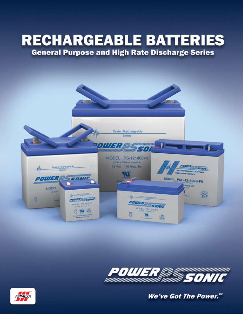
POWER-SONIC Rechargeable Batteries �
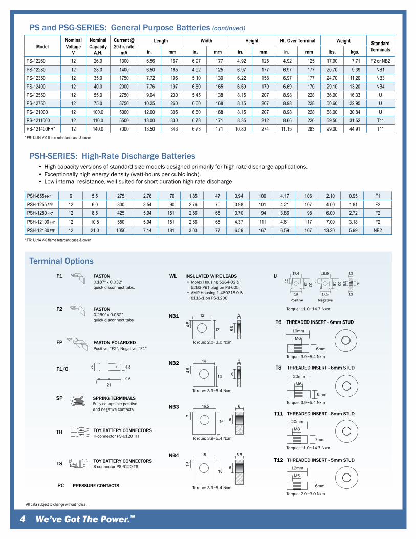
PS and PSG-SERIES: General Purpose Batteries
* FR: UL94 V-0 flame retardant case & coverAll data subject to change without notice.
ModelNominalVoltage
V
NominalCapacity
A.H.
Current @20-hr. rate
mA
Length Width Height Ht. Over Terminal Weight StandardTerminalsin. mm in. mm in. mm in. mm lbs. kgs.
PS-260 2 6.0 300 1.97 50 1.34 34 3.94 100 4.13 105 0.89 0.40 F1PS-445 4 4.5 225 1.89 48 2.09 53 3.70 94 3.86 98 1.30 0.59 F2PSG-450 4 5.0 250 3.54 90 1.94 49 2.87 73 2.87 73 1.40 0.64 F2PSG-480 4 8.0 400 3.54 90 1.94 49 4.00 102 4.00 102 2.09 0.95 F2PS-490 4 9.0 450 4.01 102 1.73 44 3.74 95 4.02 102 2.20 1.00 F2PS-4100 4 10.0 500 4.01 102 1.97 50 3.70 94 3.85 98 2.50 1.13 F1PS-605 6 0.5 25 2.24 57 0.55 14 1.97 50 1.97 50 0.20 0.09 WLPS-610 6 1.1 55 2.00 51 1.65 42 2.00 51 2.20 56 0.44 0.20 F1PS-612 6 1.4 70 3.82 97 0.94 24 2.00 51 2.20 56 0.66 0.30 F1PSG-625 6 2.5 125 4.15 105 1.63 41 2.70 69 2.70 69 1.17 0.53 F1PS-628 6 2.9 145 2.60 66 1.30 33 3.86 98 4.06 103 1.30 0.59 F1PS-630 6 3.5 175 5.28 134 1.34 34 2.35 60 2.56 65 1.37 0.62 F1PS-632 6 3.5 175 2.60 66 1.30 33 4.65 118 4.80 122 1.37 0.62 F1PS-640 6 4.5 225 2.76 70 1.86 47 3.94 100 4.25 108 1.60 0.73 F1PS-650LS & LF 6 5.0 250 2.64 67 2.64 67 3.94 100 4.64 118 1.80 0.82 F1 or SPPSG-650 6 5.0 250 5.28 134 1.94 49 3.00 76 3.00 76 2.15 0.98 F2PS-665 6 6.5 325 3.86 98 2.20 56 3.78 96 4.02 102 2.70 1.22 FPPS-670 6 7.0 350 5.95 151 1.34 34 3.70 94 3.94 100 2.42 1.10 F1PSG-680 6 8.0 400 5.28 134 1.94 49 3.98 101 3.98 101 3.19 1.45 F2PS-682 6 9.0 450 3.86 98 2.20 56 4.65 118 4.72 120 3.20 1.45 F1PS-6100 6 12.0 600 5.95 151 2.00 51 3.70 94 3.86 98 4.30 1.95 F1 or F2PS-6120FP 6 13.0 650 4.25 108 2.80 71 5.55 141 5.55 141 4.80 2.18 FPPS-6120 Toy 6 13.0 650 4.25 108 2.80 71 5.55 141 5.55 141 4.80 2.18 TH or TSPS-6200 6 20.0 1000 6.18 157 3.27 83 4.92 125 4.92 125 7.10 3.22 NB1PS-6360 6 36.0 1800 6.25 159 3.35 85 6.50 165 6.93 176 12.10 5.49 F2 or NB1PS-6580 6 58.0 2900 7.28 185 4.41 112 8.07 205 8.07 205 19.50 8.85 F2PS-62000 6 210.0 10500 12.05 306 6.65 169 8.65 220 8.96 228 63.93 29.00 T8PS-832 8 3.2 160 5.29 134 1.42 36 2.49 63 2.70 69 1.65 0.75 F1PS-1208 12 0.8 40 3.78 96 0.98 25 2.44 62 n/a n/a 0.77 0.35 WLPS-1212 12 1.4 70 3.78 96 1.69 43 2.04 52 2.28 58 1.20 0.54 F1PS-1220 12 2.5 125 7.00 178 1.38 35 2.36 60 2.56 65 2.10 0.95 F1PS-1221 12 2.0 100 5.63 143 0.94 24 2.56 65 2.56 65 1.30 0.59 PCPS-1221S 12 2.0 100 5.91 150 0.80 20 3.52 89 n/a n/a 1.50 0.68 F1/0PS-1223 12 2.3 115 7.17 182 0.94 24 2.40 61 2.40 61 1.70 0.77 PCPS-1227 12 2.9 145 3.11 79 2.20 56 3.90 99 4.13 105 2.40 1.09 F1PS-1228 12 2.8 140 5.24 133 1.30 33 3.82 97 4.09 104 2.60 1.18 F1PS-1229 12 2.9 145 7.00 178 1.38 35 2.36 60 2.60 66 2.30 1.04 F1PS-1230 12 3.4 170 5.24 133 2.64 67 2.36 60 2.60 66 2.90 1.32 F1PS-1238 12 3.8 190 7.68 195 1.85 47 2.91 74 2.91 74 3.50 1.59 F1PS-1250 12 5.0 250 3.54 90 2.76 70 3.98 101 4.21 107 3.50 1.59 F1 or F2PS-1251FP 12 5.4 270 5.50 140 1.90 48 4.00 102 4.06 103 4.10 1.86 FPPS-1270 12 7.0 350 5.95 151 2.56 65 3.70 94 3.86 98 4.80 2.18 F1 or F2PS-1272 12 7.2 360 5.95 151 2.56 65 3.70 94 3.86 98 5.80 2.63 F1 or F2PS-1282L 12 9.0 450 7.72 196 2.20 56 4.65 118 4.65 118 6.90 3.13 F1PS-1282S 12 9.0 450 3.86 98 4.40 112 4.65 118 4.65 118 6.90 3.13 F1PS-1290 12 9.0 450 5.95 151 2.56 65 3.70 94 3.86 98 6.00 2.72 F2PS-12100 12 12.0 600 5.95 151 4.00 102 3.70 94 3.86 98 8.14 3.69 F1 or F2PS-12120 12 12.0 600 5.95 151 3.86 98 3.70 94 3.94 100 7.92 3.59 F2PS-12120L 12 12.0 600 8.45 215 2.75 70 5.75 146 5.75 146 8.80 3.99 FPPS-12140 12 14.0 700 5.95 151 3.86 98 3.70 94 3.94 100 9.25 4.20 F2PS-12180 12 18.0 900 7.13 181 3.00 76 6.59 167 6.59 167 12.60 5.72 F2 or NB2
� We’ve Got The Power.™
Terminal Options
PSH-SERIES: High-Rate Discharge Batteries
20mm
6mm
M6
20mm
7mm
M8
FASTON0.187" x 0.032" quick disconnect tabs.
FASTON0.250" x 0.032" quick disconnect tabs
TOY BATTERY CONNECTORSH-connector PS-6120 TH
F1
SPRING TERMINALSFully collapsible positiveand negative contacts
SP
F2
F1/0
FASTON POLARIZEDPositive: “F2”, Negative: “F1”
FP
INSULATED WIRE LEADS • Molex Housing 5264-02 & 5263-PBT plug on PS-605 • AMP Housing 1-480318-0 & 8116-1 on PS-1208
WL
16mm
6mm
M6
THREADED INSERT - 6mm STUDT6
THREADED INSERT - 6mm STUDT8
THREADED INSERT - 8mm STUDT11
12mm
6mm
M5
THREADED INSERT - 5mm STUDT12
PRESSURE CONTACTSPC
TH
TOY BATTERY CONNECTORSS-connector PS-6120 TSTS
NB1 12
4.8
12 5.6
2
NB2 14
4.5
13 6
2
NB3 16.5
7
16
21
6
6
6 4.8
0.6
NB4 15
7.5
186
5.5
Torque: 2.0~3.0 Nxm
Torque: 2.0~3.0 Nxm
Torque: 11.0~14.7 Nxm
Torque: 3.9~5.4 Nxm
Torque: 3.9~5.4 Nxm
Torque: 3.9~5.4 Nxm
Torque: 3.9~5.4 Nxm
Torque: 3.9~5.4 Nxm
U
Torque: 11.0~14.7 Nxm
18 22
17.4
10 10 9
18 22
15.9
8.5
13
13
17.519Positive Negative
* FR: UL94 V-0 flame retardant case & cover
• High capacity versions of standard size models designed primarily for high rate discharge applications. • Exceptionally high energy density (watt-hours per cubic inch). • Low internal resistance, well suited for short duration high rate discharge
PSH-655 FR* 6 5.5 275 2.76 70 1.85 47 3.94 100 4.17 106 2.10 0.95 F1PSH-1255 FR* 12 6.0 300 3.54 90 2.76 70 3.98 101 4.21 107 4.00 1.81 F2PSH-1280 FR* 12 8.5 425 5.94 151 2.56 65 3.70 94 3.86 98 6.00 2.72 F2PSH-12100 FR* 12 10.5 550 5.94 151 2.56 65 4.37 111 4.61 117 7.00 3.18 F2PSH-12180 FR* 12 21.0 1050 7.14 181 3.03 77 6.59 167 6.59 167 13.20 5.99 NB2
All data subject to change without notice.
ModelNominalVoltage
V
NominalCapacity
A.H.
Current @20-hr. rate
mA
Length Width Height Ht. Over Terminal Weight StandardTerminalsin. mm in. mm in. mm in. mm lbs. kgs.
PS-12260 12 26.0 1300 6.56 167 6.97 177 4.92 125 4.92 125 17.00 7.71 F2 or NB2PS-12280 12 28.0 1400 6.50 165 4.92 125 6.97 177 6.97 177 20.70 9.39 NB1PS-12350 12 35.0 1750 7.72 196 5.10 130 6.22 158 6.97 177 24.70 11.20 NB3PS-12400 12 40.0 2000 7.76 197 6.50 165 6.69 170 6.69 170 29.10 13.20 NB4PS-12550 12 55.0 2750 9.04 230 5.45 138 8.15 207 8.98 228 36.00 16.33 UPS-12750 12 75.0 3750 10.25 260 6.60 168 8.15 207 8.98 228 50.60 22.95 UPS-121000 12 100.0 5000 12.00 305 6.60 168 8.15 207 8.98 228 68.00 30.84 UPS-1211000 12 110.0 5500 13.00 330 6.73 171 8.35 212 8.66 220 69.50 31.52 T11PS-121400FR* 12 140.0 7000 13.50 343 6.73 171 10.80 274 11.15 283 99.00 44.91 T11
PS and PSG-SERIES: General Purpose Batteries (continued)
* FR: UL94 V-0 flame retardant case & cover

POWER-SONIC Rechargeable Batteries �
CAPA
CITY
VAR
IATI
ON
BY
CUR
REN
T LO
ADW
hen
a ba
ttery
dis
char
ges
curr
ent a
t a c
onst
ant r
ate,
its
capa
city
cha
nges
acc
ordi
ng
to th
e am
pera
ge lo
ad. C
apac
ity in
crea
ses
whe
n th
e di
scha
rge
curr
ent i
s le
ss th
an th
e 20
-hou
r rat
e an
d de
crea
ses
whe
n th
e cu
rren
t is
high
er.
The
grap
h ab
ove
show
s ca
paci
ty c
urve
s fo
r maj
or P
ower
-Son
ic b
atte
ry m
odel
s w
ith
diffe
rent
am
pere
-hou
r rat
ings
. Am
pera
ge is
on
the
horiz
onta
l sca
le a
nd th
e tim
e
elap
sed
is o
n th
e ve
rtic
al s
cale
; the
pro
duct
of t
hese
val
ues
is th
e ca
paci
ty.
Prop
er s
elec
tion
of th
e ba
ttery
for a
spe
cific
app
licat
ion
can
be m
ade
from
this
gra
ph
if th
e re
quire
d tim
e an
d cu
rren
t are
kno
wn.
For
exa
mpl
e, to
det
erm
ine
the
prop
er
capa
city
of a
bat
tery
pro
vidi
ng 3
am
ps fo
r 30
min
utes
, loc
ate
the
inte
rsec
tion
of th
ese
valu
es o
n th
e gr
aph.
The
cur
ve im
med
iate
ly a
bove
that
poi
nt re
pres
ents
the
batte
ry
whi
ch w
ill m
eet t
he re
quire
men
t.
Ambie
nt tem
p. 20
o C (6
8o F)
Disc
harg
e Tim
e as a
Fun
ctio
n of
Disc
harg
e Cur
rent
Disc
harg
e tim
es re
flect
cut-o
ffvo
ltage
s whic
h var
y with
the
disch
arge
curre
nt:
LOAD
FI
NAL
CUR
RENT
V
OLTA
GE
0.05C
1.75
V/Ce
ll
0.10C
1.75
V/Ce
ll
0.20C
1.75
V/Ce
ll
0.50C
1.70
V/Ce
ll
1.00C
1.50
V/Ce
ll
2.00C
1.35
V/Ce
ll"C
" = C
apac
ity of
batte
ry
6110100 2030405080 60 234568 12182430364254
DischargeTime(hrs)minhrs
0001
Disc
harg
e Cur
rent
(Am
ps)
.02.03
.05.07
.10.2
.3.5
.6.8
12
34
56
810
2030
4050
6080
100
200
300
500
.01
0.5AH
2.3AH
2.9AH
5.0AH
6.5AH
8.0AH
12.0AH
20.0AH
40.0AH
65.0AH
0.8AH
1.1AH
1.4AH
2.0AH
2.5AH
3.5AH
4.5AH5.5AH
7.0AH
10.0AH
18.0AH
26.0AH
35.0AH
55.0AH
75.0AH
110.0AH
140.0AH
210.0AH

We’ve Got The Power.™�
ChargingCycle Applications: Limit initial current to 0.30C (C is the nominal amp hour capacity of the battery) or 30 amps, which ever is the less. Charge until battery voltage (under charge) reaches 2.45 volts per cell at 68°F (20°C). Hold at 2.45 volts per cell until current drops to approximately 0.01C ampere. Battery is fully charged under these conditions, and charger should either be disconnected or switched to “float” voltage.
“Float” or “Stand-by” Service: Hold battery across constant voltage source of 2.25 to 2.30 volts per cell continuously. When held at this voltage, the battery will seek its own current level and maintain itself in a fully charged condition.
Application NotesContinuous over- or undercharging is the single worst enemy of a lead-acid battery. Caution should be exercised to insure that
the charger is disconnected after cycle charging, or that the float voltage is set correctly.
Because there is a chance of off-gassing hydrogen and oxygen if the battery is overcharged, it is important to provide adequate air circulation. Never charge or discharge a battery in a hermetically sealed enclosure.
Batteries should not be stored in a discharged state (or in a hot place). If a battery is discharged for some time it may not readily take a charge. To overcome this, leave the charger connected and the battery should eventually begin to accept a charge.
Due to the self-discharge characteristics of this type of battery, it is imperative that they be charged within 6 months of storage, otherwise permanent loss of capacity might occur as a result of sulfation. To prolong shelf life without charging, store batteries at 50°F (10°C) or less.
Performance Characteristics
120
100
80
60
40
20
0
Number of Cycles
Life Characteristics in Cyclic Use Life Characteristics in Stand-by Use
Effect of Temperature on Capacity Self-Discharge Characteristics
1. Discharge Current 0.2C (Final Voltage 1.7V/Cell)2. Charge Current: 0.1C3. Ambient Temperature: 20o C to 25 o C (68o F to 77 o F)
Rete
ntio
nCa
pacit
y(%
)
DischargeDepth 100%
DischargeDepth 50%
DischargeDepth 30%
100
80
60
40
20
0
Ambient Temperature 20˚C (68˚F)
Float Charging Voltage2.25 - 2.30 V/Cell
Years
Rete
ntio
n Ca
pacit
y (%
)
Characteristic Discharge Curves
13
12
11
10
9
8
0
6.5
6.0
5.5
5.0
4.5
4.0
1 2 3 5 10 20 30 10 2 3 5 20 30 60min h
Discharge Time @ 0°C (32°F)
0.05C0.1C0.175C0.25C
0.6C
1C2C3C
Batte
ry V
olta
ge (V
)
Characteristic Discharge Curves
13
12
11
10
9
8
0
6.5
6.0
5.5
5.0
4.5
4.0
1 2 3 5 10 20 30 10 2 3 5 20 30 60min h
Discharge Time @ 20°C (68°F)
0.05C0.1C0.175C0.25C
0.6C
1C2C3C
Batte
ry V
olta
ge (V
)
Temperature (°C)
100
80
60
40
00 2 4 6 8 10 12 14 16 18 20
Storage Period (Months)
Capa
city R
eten
tion
Ratio
(%)
40°C(104°F)
30°C(86°F)
20°C(68°F)
5°C(41°F)
Charging is not necessary unless 100% of capacity is required.
Charging before use is necessary to recover full capacity.
Charge may fail to restore full capacity. Do not let battery reach this state
Perc
ent(%
) of C
apac
ity
120
110
80
60
40
20
-40 -30 -20 -10 0 10 20 30 40 50 60
0.05 C0.10 C0.25 C
0.50 C
1 C
0

Container & case sealingCase and lid material is ABS, high impact, resin with high resistance to chemicals and flammability. Case and cover are made of non-conductive ABS plastic to UL94-HB or UL94 V-O. Depending on the model the case sealing is ultrasonic, epoxy or heat seal.
Relief valveIn case of excessive gas pressure build-up inside the battery, the relief valve will open and relieve the pressure. The one-way valve not only ensures that no air gets into the battery where the oxygen would react with the plates causing internal discharge, but also represents an important safety device in the event of excessive overcharge. Vent release pressure is between 2-6 psi; the seal ring material is neoprene rubber.
TerminalsDepending on the model, batteries come either with AMP Faston type terminals made of tin plated brass, post type terminals of the same composition with threaded nut and bolt hardware, or heavy duty flag terminals made of lead alloy. A special epoxy is used as sealing material surrounding the terminals.
ElectrolyteImmobilized dilute sulfuric acid: H2S04.
SeparatorsPower-Sonic separators are made of non-woven glass fiber cloth with high heat and oxidation resistance. The material further offers superior electrolyte absorption and retaining ability, as well as excellent ion conductivity.
Plates (electrodes)Power-Sonic utilizes the latest technology and equipment to cast grids from a lead-calcium alloy free of antimony. The small amount of calcium and tin in the grid alloy imparts strength to the plate and guarantees durability even in extensive cycle service. Lead dioxide paste is added to the grid to form the electri-cally active material. In the charged state, the negative plate paste is pure lead and that of the positive lead dioxide. Both of these are in a porous or spongy form to optimize surface area and thereby maximize capacity. The heavy duty lead calcium alloy grids provide an extra margin of performance and life in both cyclic and float applications and give unparal-leled recovery from deep discharge
POWER-SONIC Rechargeable Batteries �
Battery Construction
Typical ApplicationsPower Sources • Back-up power • Computers • UPS
Communications • GPS equipment • Marine communications • Telecommunication systems
Lighting • Emergency lighting • Exit lights • Hand held lights
Security Systems • Burglar / Fire alarms • Monitoring alarms • Metal detectors
Automotive • Electronic memory accessories • Braking / Fuel systems
Recreation • Fish finders • Ride-on toys • Electrical bicycles/scooters
Portable Equipment • Audio-visual devices • Test and measuring equipment • Consumer electronics
Monitoring Equipment • Fiber-optic test equipment • Scientific instruments • Weather instrumentation
Agricultural • Livestock/game feeders • Containment fencing
Military • Aerospace • Aircraft instrumentation • Fire control systems
Miscellaneous • Invisible fences • DC power lifts • Floor scrubbers • Laser products • Robotics • Advertising signs
Power-sonic offers a wide range of chargers suitable for batteries up to 100AH. Please refer to the Charger Selection Guide in our specification sheets for “C-Series Switch Mode Chargers” and “Transformer Type A and F Series”. Please contact our technical department for advice if you have difficulty in locating suitable models.
Battery Chargers

Quality is always #1 We employ IQC, PQC and ISO 9001 Quality Management
Systems to test materials, monitor manufacturing processes and
evaluate finished products prior to shipment. All our batteries are
100% tested with advanced computer equipment prior to being
released for sale.
Power-Sonic management and staff are committed to providing
the best possible service to satisfy our customer’s needs, and
fulfill our undertaking to deliver top grade products on time and
at a competitive price.
Our batteries are manufactured to international standards including JIS, DIN and IEC and have UL and CE certification.
Corporate Headquarters and Domestic Sales Power-Sonic Corporation • 7550 Panasonic Way • San Diego, CA 92154 • USAPhone: (619) 661-2020 • Fax: (619) 661-3650Email Sales: [email protected] • Email Customer Service: [email protected]
International Sales Power-Sonic Corporation • P.O. Box 5242 • Redwood City, CA 94063 • USAPhone: (650) 364-5001 • Fax: (650) 366-3662Email Sales: [email protected]
European Sales Power-Sonic Europe, Ltd. • 3 Buckingham Square, Hurricane Way • Wickford, Essex SS11 8YQ • EnglandPhone: (1268) 560686 • Fax: (1268) 560902Email Sales: [email protected] • Website: www.power-sonic.co.uk
www.power-sonic.com© Copyright 2009. Power-Sonic Corporation. All rights reserved. REV0109


