cp-s 24/5.0 cp-s 24/10.0 cp-s 24/20 - library.e.abb.com · todas las indicaciones son a título...
TRANSCRIPT
4 42
7 01
4 52
00
11S
VC
427
014
M 5
200
Prin
ted
in t
he F
ed.
Rep
. of
Ger
man
y
CP-S 24/5.0CP-S 24/10.0CP-S 24/20.0
(D) Betriebs- und MontageanleitungPrimär getaktete Schaltnetzteile CP-S ReiheHinweis: Diese Betriebs- und Montageanleitung enthält nicht sämtliche Detailinformationen zu allen Typen derProduktreihe und kann auch nicht jeden Einsatzfall der Produkte berücksichtigen. Alle Angaben dienen ausschließlichder Produktbeschreibung und sind nicht als zugesicherte Eigenschaften im Rechtssinne aufzufassen.Weiterführende Informationen und Daten erhalten Sie in den Katalogen und Datenblättern der Produkte, über dieörtliche ABB-Niederlassung sowie auf der ABB Homepage unter http://www.abb.com. Technische Änderungen jederzeitvorbehalten. In Zweifelsfällen gilt der deutsche Text.
Nur von einer entsprechend qualifizierten Fachkraft zu installieren. Dabei landesspezifische Vorschriften (z.B. VDE, etc.)beachten. Vor der Installation diese Betriebs- und Montageanleitung sorgfältig lesen und beachten.Die Geräte sind wartungsfreie Einbaugeräte.
(GB) Operating and installation instructionsPrimary switch mode power supplies CP-S rangeNote: These operating and installation instructions cannot claim to contain all detailed information of all types of this productrange and can even not consider every possible application of the products. All statements serve exclusively to describe theproduct and have not to be understood as assured characteristics with legal force. Further information and data is obtainablefrom the catalogues and datasheets of this product, from the local ABB sales organisations as well as on the ABB homepagehttp://www.abb.com. Subject to change without prior notice. The German text applies in cases of doubt.
The device must be installed by qualified persons only and in accordance with the specific nationalregulations (e.g., VDE, etc.). Before installing this unit, read these operating and installationinstructions carefully and completely. These devices are maintenance-free chassis-mounted units.
(F) Instructions de service et de montageAlimentations à découpage primaire, gamme CP-SNote: Ces instructions de service et de montage ne contiennent pas toutes les informations relatives à tous les types de cettegamme de produits et ne peuvent pas non plus tenir compte de tous les cas d’application. Toutes les indications ne sontdonnées qu’à titre de description du produit et ne constituent aucunes obligations légales. Pour de plus amples informations,veuillez-vous référer aux cataloges et aux fiches techniques des produits, à votre agence ABB ou à notre sitehttp://www.abb.com. Sous réserve de modifications techniques. En cas de divergences, le texte allemand fait foi.
L’installation de ces produits doit être réalisée uniquement par une personne compétente et enconformité avec les prescriptions nationales (p.e. VDE, etc.). Avant l’installation de cet appareilveuillez lire l’intégralité de ces instructions. Ces produits sont des appareils encliquetablesqui ne nécessitent pas d’entretien.
(E) Instrucciones de servicio y de montajeFuentes de alimentación de conmutación primaria, serie CP-SNota: Estas instrucciones no contienen todas las informaciones detalladas relativas a todos los tipos del productoni pueden considerar todos los casos de operación. Todas las indicaciones son a título descriptivo del producto y noconstituyen obligaciones legales. Para más información, consulte los catálogos, las hojas de características, lasucursal local de ABB o la Web http://www.abb.com. Sujeto a cambios técnicos sin previo aviso. En caso de duda,prevalece el texto alemán.
La instalación debe llevarse a cabo sólo por personal especializado. Es necesario respetar lasnormas especificas del país (p.ej. VDE, etc.). Antes de la instalación lea completamente estasinstrucciones. Estos aparatos son equipos para su montaje en conjuntos y son de libre mantenimiento.
(I) Istruzioni per l’uso ed il montaggioAlimentatori a commutazione primaria, serie CP-SNota: Le presenti istruzioni per l’uso ed il montaggio non contengono tutte le informazioni dettagliate su tutta lagamma di prodotto e non possono trattare tutti i casi applicativi. Tutte le indicazioni servono esclusivamente adescrivere il prodotto e non sono da interpretare come caratteristiche garantite con valore di legge. Per ulterioriinformazioni consultare i cataloghi ed i data sheet dei prodotti, o la nostra homepage http://www.abb.com/, oppurerivolgersi alla locale filiale ABB. Ci riserviamo di eventuali modifiche tecniche. In caso di differenze o problemi è valido il testotedesco.
Installazione solo a cura di personale specializzato. Bisogna osservare le specifiche normenazionali (p.e. VDE, etc.). Prima dell’installazione leggere attentamente le seguenti istruzioni.Questi prodotti sono apparecchi ad incasso, che non hanno bisogno di manutenzione.
ABB Stotz-Kontakt GmbHHauptstr. 14-1678132 Hornberg / Germanywww.abb.com/lowvoltage -> Control Products -> Power Supplies
2
I
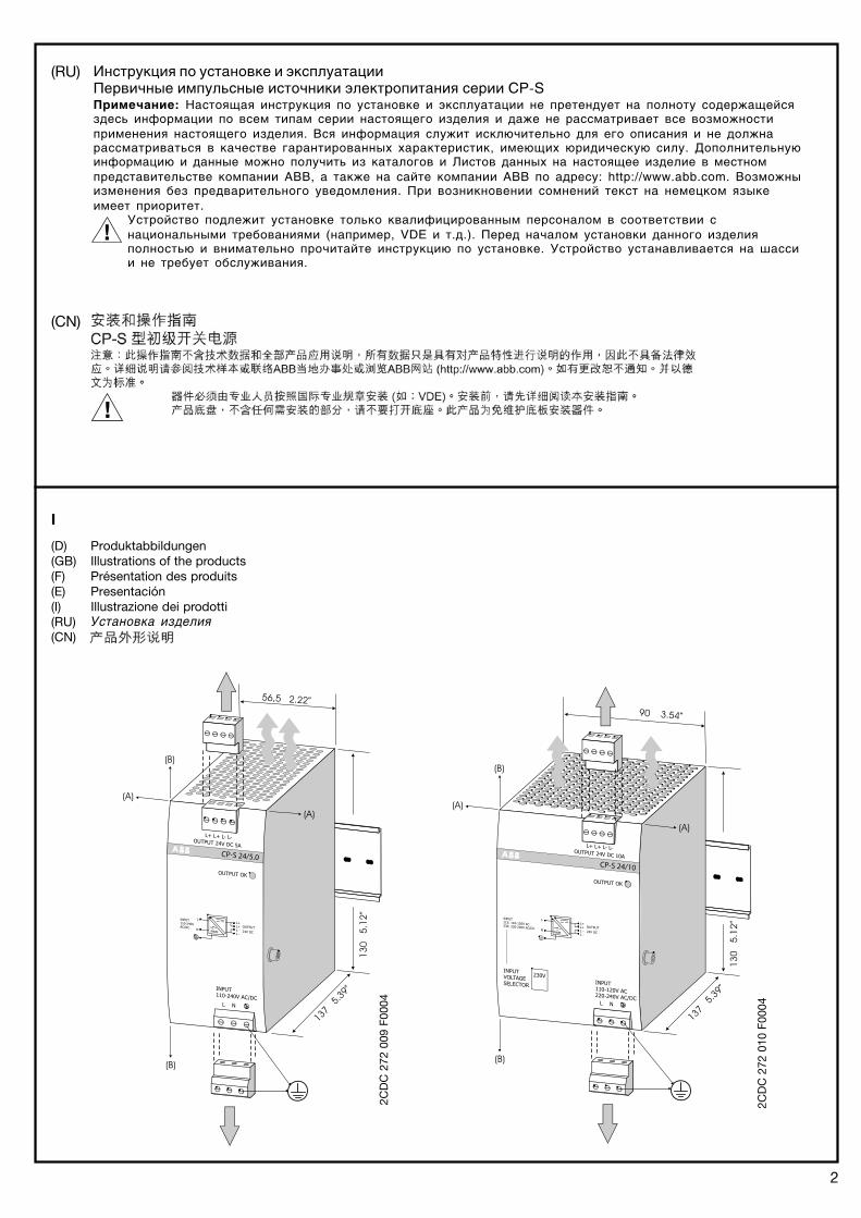
(D) Produktabbildungen(GB) Illustrations of the products(F) Présentation des produits(E) Presentación(I) Illustrazione dei prodotti(RU)(CN)
2CD
C 2
72 0
09 F
0004
2CD
C 2
72 0
10 F
0004
(RU) Инструкция по установке и эксплуатацииПервичные импульсные источники электропитания серии CP�SПримечание: Настоящая инструкция по установке и эксплуатации не претендует на полноту содержащейсяздесь информации по всем типам серии настоящего изделия и даже не рассматривает все возможностиприменения настоящего изделия. Вся информация служит исключительно для его описания и не должнарассматриваться в качестве гарантированных характеристик, имеющих юридическую силу. Дополнительнуюинформацию и данные можно получить из каталогов и Листов данных на настоящее изделие в местномпредставительстве компании АВВ, а также на сайте компании АВВ по адресу: http://www.abb.com. Возможныизменения без предварительного уведомления. При возникновении сомнений текст на немецком языкеимеет приоритет.
Устройство подлежит установке только квалифицированным персоналом в соответствии снациональными требованиями (например, VDE и т.д.). Перед началом установки данного изделияполностью и внимательно прочитайте инструкцию по установке. Устройство устанавливается на шассии не требует обслуживания.
Установка изделия
(CN)
III
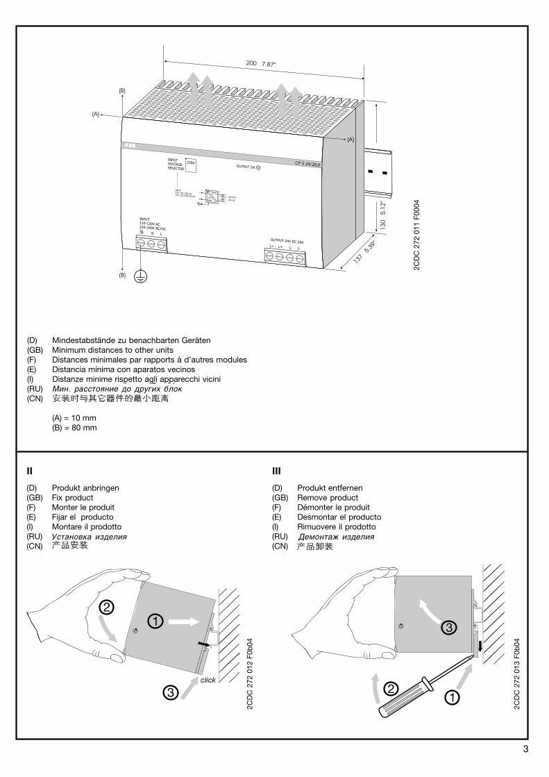
(D) Produkt entfernen(GB) Remove product(F) Démonter le produit(E) Desmontar el producto(I) Rimuovere il prodotto(RU)(CN)
3
2CD
C 2
72 0
11 F
0004
2CD
C 2
72 0
13 F
0b04
2CD
C 2
72 0
12 F
0b04
(D) Mindestabstände zu benachbarten Geräten(GB) Minimum distances to other units(F) Distances minimales par rapports à d’autres modules(E) Distancia mínima con aparatos vecinos(I) Distanze minime rispetto agli apparecchi vicini(RU)(CN)
(A) = 10 mm(B) = 80 mm
p g ppМин. расстояние до других блок
pУстановка изделия
pДемонтаж изделия
II
(D) Produkt anbringen(GB) Fix product(F) Monter le produit(E) Fijar el producto(I) Montare il prodotto(RU)(CN)
Графики зависимости от температуры (Vout = 24 В)V/I Характеристические кривые при Ta = 25 oC
Параллельное включение для резрвирования
4
2CD
C 2
72 0
03 F
0004
2CD
C 2
72 0
06 F
0004
2CD
C 2
72 0
04 F
0004
2CD
C 2
72 0
75 F
0004
2CD
C 2
72 0
05 F
0004
2CD
C 2
72 0
088
F000
4
CP
-S 2
4/5.
0C
P-S
24/
10.0
CP
-S 2
4/20
.0
CP-S1. n. CP-S
L+ L+ L- L-
Ir1 Irn
2CD
C 2
72 0
34 F
0207
ILoad � (n-1) * Ir
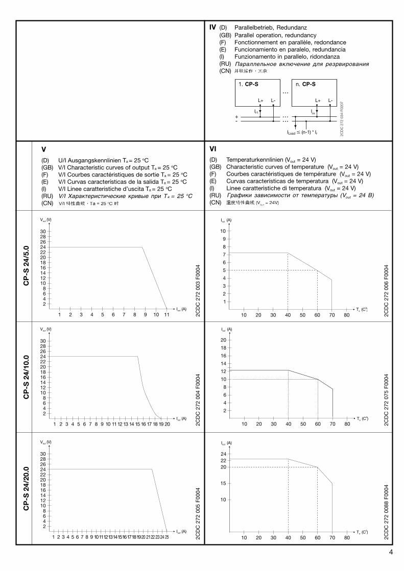
IV (D) Parallelbetrieb, Redundanz(GB) Parallel operation, redundancy(F) Fonctionnement en parallèle, redondance(E) Funcionamiento en paralelo, redundancia(I) Funzionamento in parallelo, ridondanza(RU)(CN)
V(D) U/I Ausgangskennlinien Ta = 25 oC(GB) V/I Characteristic curves of output Ta = 25 oC(F) V/I Courbes caractéristiques de sortie Ta = 25 oC(E) V/I Curvas características de la salida Ta = 25 oC(I) V/I Linee caratteristiche d’uscita Ta = 25 oC(RU)(CN)
VI(D) Temperaturkennlinien (Vout = 24 V)(GB) Characteristic curves of temperature (Vout = 24 V)(F) Courbes caractéristiques de température (Vout = 24 V)(E) Curvas características de temperatura (Vout = 24 V)(I) Linee caratteristiche di temperatura (Vout = 24 V)(RU)(CN)
5
(D) Sicherheits- und WarnhinweiseAnlage freischalten!Vor Installations-, Wartungs- oder Änderungsarbeiten: Anlage spannungsfrei schalten, vor Wiedereinschalten sichern.
Vor Inbetriebnahme:Achtung! Unsachgemäße Installation/Betrieb kann die Sicherheit beeinträchtigen und zu Betriebsstörungen oder zurZerstörung des Gerätes führen. Vor der Inbetriebnahme ist Folgendes sicherzustellen:• Netzanschluss gemäß den landesspezifischen Vorschriften für Schutzklasse I durchführen• Zuleitungen und Gerät ausreichend absichern. Eine Trenneinrichtung für das Netzteil vorsehen, um das Gerät und
die Zuleitungen im Bedarfsfall zu unterbrechen.• Schutzleiter an die Klemme (siehe Abbildung I) anschließen• Ausgangsleitungen für den Ausgangsstrom des Netzteils dimensionieren und polrichtig anschließen.• Abstände zu benachbarten Geräten beachten (siehe Abbildung I) um eine ausreichende Kühlung zu gewährleisten• Der Netzwahlschalter „INPUT VOLTAGE SELECTOR“ muss, sofern vorhanden (CP-S 24/10.0, CP-S 24/20.0),
richtig eingestellt sein.• Schrauben am Gehäuse dienen der geräteinternen Erdung. Nicht entfernen! Keine Kabel anschließen!
Im Betrieb:• Keinerlei Änderungen an der Installation (primär- und sekundärseitig) vornehmen! (Starkstrom!).
Gefahr von Lichtbögen und elektrischem Schlag (Lebensgefahr)!• Bei CP-S 24/5.0 und CP-S 24/10.0 Steckverbinder nur leistungslos betätigen!• Verbrennungsgefahr: In Abhängigkeit der Betriebsbedingungen kann die Gehäusetemperatur hohe Werte annehmen.• Löst die interne Sicherung aus, liegt mit hoher Wahrscheinlichkeit ein Gerätedefekt vor.
In diesem Fall ist eine Überprüfung des Schaltnetzteils durch den Hersteller erforderlich.
Achtung: Hochspannung! Gespeicherte Energie! Gefährliche Energie am Ausgang!In den Netzteilen befinden sich Bauelemente mit hoher gespeicherter Energie und Stromkreise mit Hochspannung!Deshalb keine Gegenstände in das Gerät einführen und das Gerät nicht öffnen. Bei einigen Geräten dieser Serie kann derAusgang gefährlich hohe Energiemengen abgeben. Sicherstellen, dass Bedienpersonal vor versehentlicher Berührungenergieführender Teile geschützt ist.
(GB) Safety instructions and warningsDisconnect system from supply network!Before any installation, maintenance or modification work: Disconnect the system from the supply network andprotect against switching on.
Before start of operation:Attention! Improper installation/operation may impair safety and cause operational difficulties or destruction of theunit. Before operation the following must be ensured:• Connect to main according to the specific national regulations for class of protection I.• Power supply cables and unit must be sufficiently fused. A disconnecting device has to be provided for the end
product to disengage unit and supply cables from supply mains if required.• The protective earth conductor must be connected to the terminal (see figure I)• Rate the output lines for the output current of the power supply and connect them with the correct polarity.• In order to ensure sufficient air-cooling the distance to other devices has to be considered (see figure I)• If present (CP-S 24/10.0, CP-S 24/20.0), the „INPUT VOLTAGE SELECTOR“ must be set properly.• Screws at the enclosure are for internal grounding. Do not remove them! Do not connect cables!
In operation:• Do not modify the installation (primary and secondary side)! High current! Risk of electric arcs and electric shock
(danger to life)!• (Dis)connect the plug connector of CP-S 24/5.0 and CP-S 24/10.0 only when the power is off!• Risk of burns: Depending on the operation conditions the enclosure can become very hot• If the internal fuse blows, most probably the device is defective. In this case, an examination of the switch mode power
supply by the manufacturer is necessary.
Warning: High voltage! Stored energy! Energy hazard at output!The power supplies contain components with high stored energy and circuits with high voltage! Do not introduceany objects into the unit, and do not open the unit. With some units of this range the output is capable of providinghazardous energy. Ensure that the service personnel is protected against inadvertent contact with parts carrying energy.
(F) Indications de sécurité et mises en gardeMettre l’installation hors tension!Avant le début des travaux d’installation, d’entretien ou de modification : mettre le module hors tension et s’assurerqu’il ne peut pas être remis sous tension par erreur.
Avant la mise en service:Attention! Une installation non adaptée peut diminuer la sécurité, provoquer des disfonctionnements et amener ladestruction du module. Avant la mise en service il faut veiller aux points suivants :• Le raccordement au réseau doit être effectué en conformité avec les prescriptions appliquées dans le pays
concerné pour la classe de protection I• Protéger suffisamment les câbles et le module. Un dispositif de coupure doit être prévu en tête de l’appareil de
manière à ce qu’il soit isolé des câbles d’alimentation si besoin.• Raccorder le fil de protection à la borne (voir Fig. I).• Tous les câbles de sortie doivent être dimensionnés pour le courant de sortie et raccordés correctement par
rapport à la polarité.• Considérer la distance du module aux autres modules (voir Fig. I) pour garantir un refroidissement suffisant.
6
• L’interrupteur de sélection du réseau „INPUT VOLTAGE SELECTOR“ doit être correctement réglé s’il existe(CP-S 24/10.0, CP-S 24/20.0).
• Les vis du boîtier servent à la mise à la terre interne. Ne pas les retirer ! Ne pas les utiliser pour raccorder des câbles!
Sous tension:• Ne pas effectuer de changements (côté primaire et secondaire) quand le module est sous tension!
(Courant fort!). Risque de formation d’arcs et de chocs électriques (danger de mort!)• Ne manipuler le connecteur multiple des modules CP-S 24/5.0 et CP-S 24/10.0 qu’ uniquement hors tension!• Risques de brûlures: Selon les conditions d’utilisation le boîtier peut devenir très chaud.• Si le fusible interne fond, selon toute probabilité l’appareil est défectueux. Dans ce cas il faut faire examiner
l’alimentation à découpage par le producteur.
Attention: Haute tension! Energie emmagasinée! Energie dangereuse à la sortie!Le module renferme des composants emmagasinant de l’énergie et des circuits sous haute tension! Ne pasintroduire d’objets dans le module et ne pas l’ouvrir! La sortie de certains appareils peut émettre d’importantesquantités d’énergie. Il faut s’assurer que le personnel de maintenance soit protegé contre les contacts accidentelsavec des composants sous tension.
(E) Avisos de seguridadDesconecte la instalación!Antes de iniciar trabajos de instalación, mantenimiento o modificación desconecte su instalación y cerciórese deque no pueda ser conectada nuevamente por descuido.
Antes de la puesta en marcha :Atención! Una instalación incorrecta o uso inadecuado puede afectar a la seguridad y al funcionamiento, hasta ladestrucción total del aparato. Hay que comprobar lo siguiente antes de la puesta en marcha:• La conexión debe hacerse conforme a las disposiciones nacionales aplicables para la clase de protección I.• Proteger adecuadamente el aparato y los cables de alimentación. Con la intención de proteger, se debe colocar
un dispositivo de aislamiento en el equipo final de modo que, en caso necesario, quede interrumpido el paso decorriente al equipo y las líneas de alimentación
• Conectar el conductor de protección al borne (ver Fig. I)• Todos los cables de salida deben ser adecuados para la intensidad de salida del bloque de alimentación y
conectados con polarización correcta.• Tener en cuenta la distancia con aparatos vecinos (ver Fig. I) para garantizar una refrigeración suficiente.• El commutador-selector de red „INPUT VOLTAGE SELECTOR“, si procede (CP-S 24/10.0, CP-S 24/20.0), debe
estar en la posición correcta.• Los tornillos en la caja sirven para la puesta a tierra interior. No quitar! No conectar cables!
Durante el funcionamiento:• En ningún caso efectuar modificaciones de la instalación (lado primario y secundario)! Corriente de alta tensión!
Peligro de arcos voltáicos y choques eléctricos (peligro de muerte)!• Los conectores enchufables de los aparatos CP-S 24/5.0 y CP-S 24/10.0 sólo deben manipularse si no tienen
corriente!• Peligro de quemaduras: Dependiendo de las condiciones de funcionamiento, la caja puede alcanzar temperaturas elevadas• Si el fusible interno se funde, lo más probable es que el aparato esté defectuoso. En este caso, es necesario que el
fabricante examine la fuente de alimentación conmutada.
Atención: Alta tensión! Energía acumulada! Riesgo de energía en los terminales de salida!El aparato contiene conductores no protegidos bajo alta tensión, así como componentes que acumulan energíaelevada! No introducir objetos en el aparato y no abrir. En algunos dispositivos de esta serie, la salida puede emitirintensidades de energía peligrosas. Es necesario la protección del personal de servicio, para evitar contactos accidentales.
(I) Norme di sicurezza e avvertenzeDisinserire il sistema!Prima di eseguire lavori di installazione, manutenzione o modifica, disinserire il sistema, assicurarsi che sia privo ditensione e che non possa essere reinserita inavvertitamente.
Prima della messa in funzione:Attenzione! La scorretta installazione e il funzionamento inadeguato possono pregiudicare la sicurezza e portare aguasti e al danneggiamento del dispositivo. Prima della messa in funzione bisogna accertarsi del seguente:• Il collegamento alla rete deve essere conforme alle specifiche norme nazionali riguardo la classe di protezione I• L’apparecchio e i cavi d’alimentazione devono essere sicuri in modo sufficiente. Si deve prevedere un dispositivo di seziona-
mento per il terminale, in modo da poter interrompere, in caso di necessità, sia l’apparecchio che le linee di alimentazione.• Collegare il conduttore di terra al morsetto (vedere Fig. I)• Dimensionare tutti i cavi d’uscita idoneamente e collegarli con giusta polarità.• Badare alle distanze verso apparecchi vicini (vedere Fig. I) per garantire un sufficiente raffredamento.• Il selettore rete „INPUT VOLTAGE SELECTOR“, se esistente (CP-S 24/10.0, CP-S 24/20.0), deve essere regolato in
modo esatto.• Le viti poste sulla custodia servono per il collegamento a terra interno. Non togliere le viti! Non collegare cavi!
Durante il funzionamento:• Non apportare modifiche all’installazione (parte primaria e secondaria)! Corrente ad alta tensione!
Pericolo di arco voltaico e shock di corrente (Pericolo di morte)!• Azionare il connettore a spina degli apparecchi CP-S 24/5.0 e CP-S 24/10.0 senza potenza!• Pericolo di ustioni: A seconda delle condizioni di funzionamento, la custodia può diventare molto calda.• Se il fusibile interno scatta, molto probabilmente l’apparecchio è difettoso. In questo caso bisogna far esaminare
l’alimentatore a commutazione dal produttore.
7
Attenzione: Alta tensione! Energia accumulata! Energia pericolosa all’uscita!Gli alimentatori sono provvisti di componenti che accumulano moltissima energia, nonché di conduttori non protettiad alta tensione! Perciò non introdurre oggetti nell’apparecchio e non aprire l’apparecchio. In alcuni apparecchi diquesta serie l’uscita può emettere pericolosamente elevati quantitativi di energia. Provvedere alla adeguateprotezione del personale di manutenzione contro eventuali contatti fortuiti con componenti portando energia.
(RU) Инструкции по мерам безопасности и предупрежденияОтключайте систему от сети электропитания!Перед выполнением любых работ по монтажу, техническому обслуживанию или модернизации отключайтесистему от сети электропитания и принимайте меры от случайного включения.Перед началом работ:Внимание! Неправильная установка и эксплуатация устройства может привести к нарушению мер безопасностии к затруднению эксплуатации или разрушению изделия. Перед началом эксплуатации убедитесь в том, что:• Подключение к основной электросети выполнено в соответствии с конкретными национальными
требованиями для аппаратуры с классом защиты I.• Кабели электропитания и сам блок должны быть защищены соответствующими предохранителями. Должно
быть предусмотрено устройство отключения изделия и кабелей питания от основной электросети.• Проводник защитного заземления должен быть подключен к соответствующей клемме ( см. Рисунок I)• Номинальные параметры отводящих линий должны соответствовать выходному току блока питания и
подключаться с соблюдением полярности.• Для обеспечения необходимого охлаждения изделия должны выдерживаться расстояния до других
устройств (см. Рисунок I)• При наличии (CP+S 24/10.0, CP+S 24/20.0) переключателя „INPUT VOLTAGE SELECTOR“ (Выбор входного
напряжения), он должен быть установлен в правильное положение.• Винты на кожухе изделия служат для внутреннего заземления. Не вывинчивайте их! Не подключайте к ним
кабели!В процессе работы:• Не вносите изменения в конструкцию изделия (как на стороне первичного питания, так и на стороне
вторичного питания)! Протекают большие токи! Существует риск возникновения дугового разряда ипоражения электрическим током (опасно для жизни)!
• Отключайте и подключайте разъем CP+C 24/5.0 и CP+C 24/10.0 только при отключенном электропитании!• Риск ожогов: при некоторых условиях эксплуатации кожух изделия может быть очень горячим• При перегорании внутреннего предохранителя устройство, скорее всего, повреждено. В этом случае
требуется проверка импульсного блока питания на предприятии+изготовителе.Внимание! Высокое напряжение! Накопление энергии! Опасное напряжение на выходе!Источники электропитания содержат компоненты, которые хранят значительную энергию, и цепи высокогонапряжения! Не вставляйте никакие предметы в блок и не открывайте блок. Некоторые из изделий данногосемейства способны формировать на выходе опасные уровни энергии. Убедитесь в том, что обслуживающийперсонал надежно защищен от случайного контакта с деталями, по которым передается энергия.
(CN)
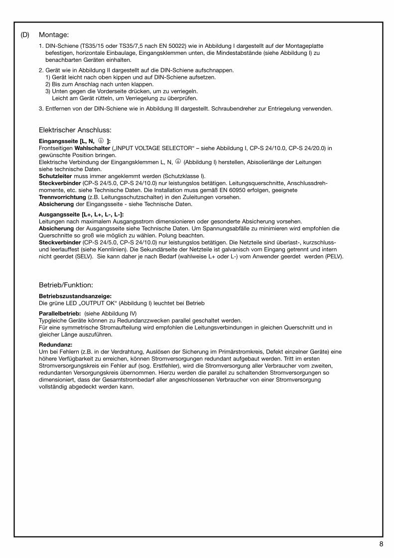
(D) Montage:
1. DIN-Schiene (TS35/15 oder TS35/7,5 nach EN 50022) wie in Abbildung I dargestellt auf der Montageplattebefestigen, horizontale Einbaulage, Eingangsklemmen unten, die Mindestabstände (siehe Abbildung I) zubenachbarten Geräten einhalten.
2. Gerät wie in Abbildung II dargestellt auf die DIN-Schiene aufschnappen.1) Gerät leicht nach oben kippen und auf DIN-Schiene aufsetzen.2) Bis zum Anschlag nach unten klappen.3) Unten gegen die Vorderseite drücken, um zu verriegeln. Leicht am Gerät rütteln, um Verriegelung zu überprüfen.
3. Entfernen von der DIN-Schiene wie in Abbildung III dargestellt. Schraubendreher zur Entriegelung verwenden.
Elektrischer Anschluss:
Eingangsseite [L, N, ]:Frontseitigen Wahlschalter („INPUT VOLTAGE SELECTOR“ – siehe Abbildung I, CP-S 24/10.0, CP-S 24/20.0) ingewünschte Position bringen.Elektrische Verbindung der Eingangsklemmen L, N, (Abbildung I) herstellen, Abisolierlänge der Leitungensiehe technische Daten.Schutzleiter muss immer angeklemmt werden (Schutzklasse I).Steckverbinder (CP-S 24/5.0, CP-S 24/10.0) nur leistungslos betätigen. Leitungsquerschnitte, Anschlussdreh-momente, etc. siehe Technische Daten. Die Installation muss gemäß EN 60950 erfolgen, geeigneteTrennvorrichtung (z.B. Leitungsschutzschalter) in den Zuleitungen vorsehen.Absicherung der Eingangsseite - siehe Technische Daten.
Ausgangsseite [L+, L+, L-, L-]:Leitungen nach maximalem Ausgangsstrom dimensionieren oder gesonderte Absicherung vorsehen.Absicherung der Ausgangsseite siehe Technische Daten. Um Spannungsabfälle zu minimieren wird empfohlen dieQuerschnitte so groß wie möglich zu wählen. Polung beachten.Steckverbinder (CP-S 24/5.0, CP-S 24/10.0) nur leistungslos betätigen. Die Netzteile sind überlast-, kurzschluss-und leerlauffest (siehe Kennlinien). Die Sekundärseite der Netzteile ist galvanisch vom Eingang getrennt und internnicht geerdet (SELV). Sie kann daher je nach Bedarf (wahlweise L+ oder L-) vom Anwender geerdet werden (PELV).
Betrieb/Funktion:
Betriebszustandsanzeige:Die grüne LED „OUTPUT OK“ (Abbildung I) leuchtet bei Betrieb
Parallelbetrieb: (siehe Abbildung IV)Typgleiche Geräte können zu Redundanzzwecken parallel geschaltet werden.Für eine symmetrische Stromaufteilung wird empfohlen die Leitungsverbindungen in gleichen Querschnitt und ingleicher Länge auszuführen.
Redundanz:Um bei Fehlern (z.B. in der Verdrahtung, Auslösen der Sicherung im Primärstromkreis, Defekt einzelner Geräte) einehöhere Verfügbarkeit zu erreichen, können Stromversorgungen redundant aufgebaut werden. Tritt im erstenStromversorgungskreis ein Fehler auf (sog. Erstfehler), wird die Stromversorgung aller Verbraucher vom zweiten,redundanten Versorgungskreis übernommen. Hierzu werden die parallel zu schaltenden Stromversorgungen sodimensioniert, dass der Gesamtstrombedarf aller angeschlossenen Verbraucher von einer Stromversorgungvollständig abgedeckt werden kann.
8
(GB) Mounting:
1. Fasten the DIN rail (TS35/15 or TS35/7,5 acc. EN 50022) as shown in Fig. I on the mounting plate, horizontalmounting position, input terminals on bottom, respect the minimum distance to other units (see Fig. I)
2. Snap on DIN rail as shown in Fig. II1) Tilt the unit slightly upwards and fit the unit on the DIN rail2) Lift it downward until it hits the stop3) Press against the bottom front side for locking Shake the unit slightly to check the locking
3. Remove the unit from the DIN rail as shown in Fig. III. Use a screwdriver for the unlocking.
Electrical connection:
Input side [L, N, ]:Set the front-face „INPUT VOLTAGE SELECTOR” (CP-S 24/10.0, CP-S 24/20.0 - see Fig. I) in desired position.Connect the input terminals L, N, (Fig. I ), stripping length of the cable – see technical data.The protective earth conductor must be connected (class of protection I).Actuate the plug connector (CP-S 24/5.0, CP-S 24/10.0) only when the power is off. Cable cross sections, torqueetc. - see technical data. The installation must be executed acc. EN 60950, provide a suitable disconnectingdevice (e.g., line protection switch) in the supply line.Fuse protection of the input side - see technical data.
Output side [L+, L+, L-, L-]:Rate the lines for the maximum output current or provide a separate fuse protection.Fuse protection of the output side - see technical data. We recommend to choose the cable cross section as largeas possible in order to minimize voltage drops. Observe the polarity.Actuate the plug connector (CP-S 24/5.0, CP-S 24/10.0) only when the power is off. The power supplies areoverload, short-circuit and no-load proof (see characteristic curve). The secondary side of the power suppliesis electrically isolated from the input and internally not earthed (SELV) and can therefore be earthed by the useraccording to the needs with L+ or L- (PELV).
Operating/Function:
Operational status indication: The green LED „OUTPUT OK“ (Fig. I) is lightening during operation.
Parallel operation: (see Fig. IV)In order to enable redundancy, devices of the same type can be connected in parallel.For a symmetric current distribution it is advisable to execute the line connections with the same crosssections and same lengths.
Redundancy:Redundant circuits are used to increase the operational reliability in case of errors (e.g., wrong wiring, blow of thefuses in the primary circuit, failure of single devices). If a fault occurs in the first power supply circuit (called initialfault), power to all loads is then supplied by the second, redundant power supply. For this reason the power supplyunits to be connected in parallel must be sized in such a way that the total current requirement of all loads can becompletely covered by one power supply unit.
9
10
(F) Montage:
1. Fixer le profilé DIN (TS35/15 ou TS35/7,5 selon EN 50022) sur la plaque de montage comme décrit dans la Fig. I,position de montage horizontale, bornes d’entrée en bas, observer les distances minimales (voir Fig. I) parrapports à d’autres modules.
2. Encliqueter le module sur le profilé DIN comme décrit dans la Fig. II1) Pousser le module légèrement en haut et le placer sur le profilé2) Pousser vers le bas jusqu’à la butée3) Pousser vers l’avant pour encliqueter Secouer légèrement pour vérifier l’encliquetage
3. Démonter du profilé DIN comme décrit dans la Fig. III. Utiliser un tournevis pour le désencliquetage.
Raccordement électrique:
Entrée [L, N, ]:Mettre l’interrupteur frontal de liaison au réseau („INPUT VOLTAGE SELECTOR“ - voir Fig. I, CP-S 24/10.0,CP-S 24/20.0 ) dans la position désirée. Raccorder les bornes d’entrée L, N, (Fig. I ), longueur des câbles àdénuder – voir Données Techniques.Le fil de protection doit toujours être raccordé (classe de protection I).Manipuler le connecteur multiple (CP-S 24/5.0, CP-S 24/10.0) uniquement hors tension. Sections de câble, couplede serrage, etc. - voir Données Techniques. L’installation doit être exécutée conformément à la directive EN 60950,prévoir un dispositif de coupure approprié (ex : disjoncteur de protection) dans les câbles d’alimentation.Protection de l’entrée - voir Données Techniques.
Sortie [L+, L+, L-, L-]:Dimensionner les lignes pour le courant de sortie maximum ou les protéger par un fusible spécial.Protection de la sortie - voir Données Techniques. Choisir des câbles de grande section, afin de réduire auminimum les chutes de tension. Faire attention à la polarité.Manipuler le connecteur multiple (CP-S 24/5.0, CP-S 24/10.0) uniquement hors tension. Le module est doté d’uneprotection électronique contre les surcharges, les courts-circuits et la marche à vide (voir courbes caractéristiques).Le côté secondaire des alimentations est isolé électriquement de l’entrée et en interne de la terre (SELV).Pour cette raison, l’utilisateur peut mettre facultativement L+ ou L- à la terre, selon les besoins (PELV).La mise à la terre d’une des polarités est obligatoire pour la sécurité des personnes.
Opération/Fonctionnement:
Indications de fonctionnement:La LED verte „OUTPUT OK“ (Fig. I) s’allume en fonctionnement.
Fonctionnement en parallèle: (voir Fig. IV)Des modules de même type peuvent être branchés en parallèle pour réaliser un circuit redondant.Pour une répartition symétrique du courant, nous conseillons de réaliser toutes les liaisons de l’alimentationsavec la même longueur et la même section de câble.
Redondance:Pour arriver à une fiabilité de fonctionnement plus élevée en cas d’erreurs (p.e. en câblage, déclenchement dufusible dans le circuit primaire, défaut d’un module unique), on peut monter des circuits redondants. En cas dedéfaut dans le circuit primaire de la première alimentation (dit premier erreur), le second module redondant prend lerelais pour assurer l’alimentation de tous les consommateurs. Pour cela, les alimentations à brancher en parallèledoivent être dimensionnées de manière à ce qu’un seul module puisse couvrir intégralement la demande totale encourant de tous les appareils consommateurs.
11
(E) Montaje
1. Fijación del perfil DIN (TS35/15 ó TS35/7,5 según EN 50022) sobre una placa de montaje como se muestra en laFig. 1, montaje en posición horizontal, los bornes de entrada deben de estar hacía abajo, tener en cuenta ladistancia mínima con aparatos vecinos (ver Fig. I)
2. Fijación del aparato en el perfil como se muestra en la Fig. II1) Posicionar el aparato en el perfil, encajar la parte superior de fijación en el perfil2) Desplazar el aparato hacía abajo para su colocación en el perfil3) Presionar sobre la cubierta para su enclavamiento. Mover ligeramente el aparato para comprobar su enclavamiento
3. Para desmontar el aparato se utiliza un destornillador como se muestra en la Fig. III.
Conexión eléctrica:
Entrada [L, N, ]:Ajustar en la parte frontal el commutador-selector de red („INPUT VOLTAGE SELECTOR“ - ver Fig. I, CP-S 24/10.0,CP-S 24/20.0) en la posición deseada. Conectar los bornes de entrada L, N, (Fig. I), longitud a pelar delconductor - ver Datos Técnicos.El conductor de protección debe ser siempre conectado (clase de protección I).Accionar los conectores enchufables (CP-S 24/5.0, CP-S 24/10.0) solo en estado de apagado.Secciones de cable, par de apriete, etc. – ver Datos Técnicos. La instalación tiene que realizarse conforme a lasespecificaciones EN 60950, preveer un dispositivo de aislamiento apropiado (p.ej. interruptores automáticos) enlos cables de entrada.Entrada protegida por fusible- ver Datos Técnicos.
Salida [L+, L+, L-, L-]:Dimensionar los cables para la intensidad de salida máxima o preveer un fusible por separado.Protección por fusible de salida – ver Datos Técnicos. Los cables deben ser de la sección más grande posiblepara reducir la caída de tensión. Tener en cuenta la polarización.Accionar los conectores enchufables (CP-S 24/5.0, CP-S 24/10.0) solo en estado de apagado. Las fuentes dealimentación están protegidas contra sobrecarga, cortocircuito y circuito abierto (ver curvas de características).El lado secundario de la fuente de alimentación está aislado eléctricamente de la entrada y no está puesto a tierrainternamente (SELV). Por ello se puede poner a tierra opcionalmente L+ o L- (PELV).
Servicio/Funcionamiento:
Indicador del estado de funcionamiento:El LED verde „OUTPUT OK“ (Fig. I) se ilumina durante el funcionamiento.
Funcionamiento en paralelo: (ver Fig. IV)Los módulos de igual tipo pueden conectarse en paralelo para realizar un circuito redundante.Para obtener un reparto de corriente simétrico, recomendamos que las conexiones de los cables se realicen conigual sección e igual longitud.
Redundancia:Los circuitos redundantes se utilizan para aumentar la seguridad de servicio en caída de un defecto (p.ej. cableadoincorrecto, fusión de los fusibles en el circuito primario, fallo en el dispositivo). Si en la primaria fuente dealimentación se tiene un defecto (llamado primer defecto), el segundo, redundante circuito de alimentación adoptala alimentación de corriente de todos los receptores. A tal fin, las fuentes de alimentación a conectar en paralelo sedimensionan de forma, que el consumo de corriente total de todos los receptores conectados se pueda cubrir porcompleto por una sola fuente de alimentación.
12
(I) Montaggio:
1. Fissare la sbarra DIN (TS35/15 o TS35/7,5 in confomità con EN 50022) come descritto nella Fig. I sulla piastra dimontaggio, montare in posizione orizzontale, morsetti d’ingresso in basso, osservare le distanze minime (vedereFig. I) rispetto agli apparecchi vicini.
2. Applicare l’apparecchio come descritto nella Fig. II sulla guida di supporto1) Tenere l’apparecchio leggermente spostato verso l’alto, poggiarlo sul supporto sagomato2) Premere verso il basso fino alla battuta3) Spingere in avanti premendo in basso fino ad avvenuto arresto Verificarne la stabilità scrollandolo leggermente
3. Rimuovere l’apparecchio dalla guida di supporto come descritto nella Fig. III. Usare un cacciavite per lo sbloccaggio.
Collegamento elettrico:
Ingresso [L, N, ]:Regolare il selletore rete sul lato frontale („INPUT VOLTAGE SELECTOR“ - vedere Fig. I, CP-S 24/10.0,CP-S 24/20.0 ). Collegare i morsetti d’ingresso L, N, (Fig. I), lunghezza di spelatura - vedere Dati Tecnici.Il conduttore di terra deve essere sempre collegato (classe di protezione I).Azionare il connettore a spina (CP-S 24/5.0, CP-S 24/10.0) solo senza potenza. Sezione della linea, coppia diserraggio etc. - vedere Dati Tecnici. L’installazione deve essere eseguita in conformità con EN 60950, prevedere unaddato dispositivo di sezionamento (p.e. interruttore automatico) per i cavi d’alimentazione.Protezione dell’ingresso - vedere Dati Tecnici.
Uscita [L+, L+, L-, L-]:Dimensionare le linee a secondo della corrente d’uscita massima oppure prevedere una protezione separata.Protezione dell’uscita - vedere Dati Tecnici. Per minimizzare cadute di tensione raccomandiamo di scegliere dellesezioni più grandi possibile. Badare alla polarità.Azionare il connettore a spina (CP-S 24/5.0, CP-S 24/10.0) solo senza potenza. Gli alimentatori sono protetti contro isovraccarichi, i cortocircuiti e il funzionamento a vuoto (vedere linee caratteristiche). La parte secondaria deglialimentatori è isolata in corrente continua dall’ingresso e internamente non collegata a terra (SELV).Pertanto può essere collegata a terra, a scelta L+ o L- (PELV).
Operazione/Funzionamento:
Visualizzazione dello stato di funzionamento:Il LED verde „OUTPUT OK“ (Fig. I) s’illumina durante l’operazione
Funzionamento in parallelo: (vedere Fig. IV)Apparecchi dello stesso tipo possono essere collegati in parallelo per realizzare un circuito ridondante.Per ottenere una ripartizione di corrente simmetrica si raccomanda di realizzare tutti i collegamenti di linee conla stessa sezione e con la stessa lunghezza.
Ridondanza:Per aumentare l’affidabilità di funzionamento in caso di errori (p.e. di cablaggio, scatto del fusibile nel circuito dicorrente primario, difetto di un apparecchio singolo), si può costruire un circuito di corrente ridondante.Se sorge un difetto nel primo circuito di alimentazione di corrente (cosiddetto primo errore), il secondo, ridondantecircuito di alimentazione s’incarica dell’alimentazione di corrente di tutti i carichi. Perciò è necessario dimensionaregli alimentatori da collegare in parallelo in modo che il consumo di corrente totale di tutti i carichi collegati possaessere coperto completamente da un solo alimentatore.
13
) Монтаж:
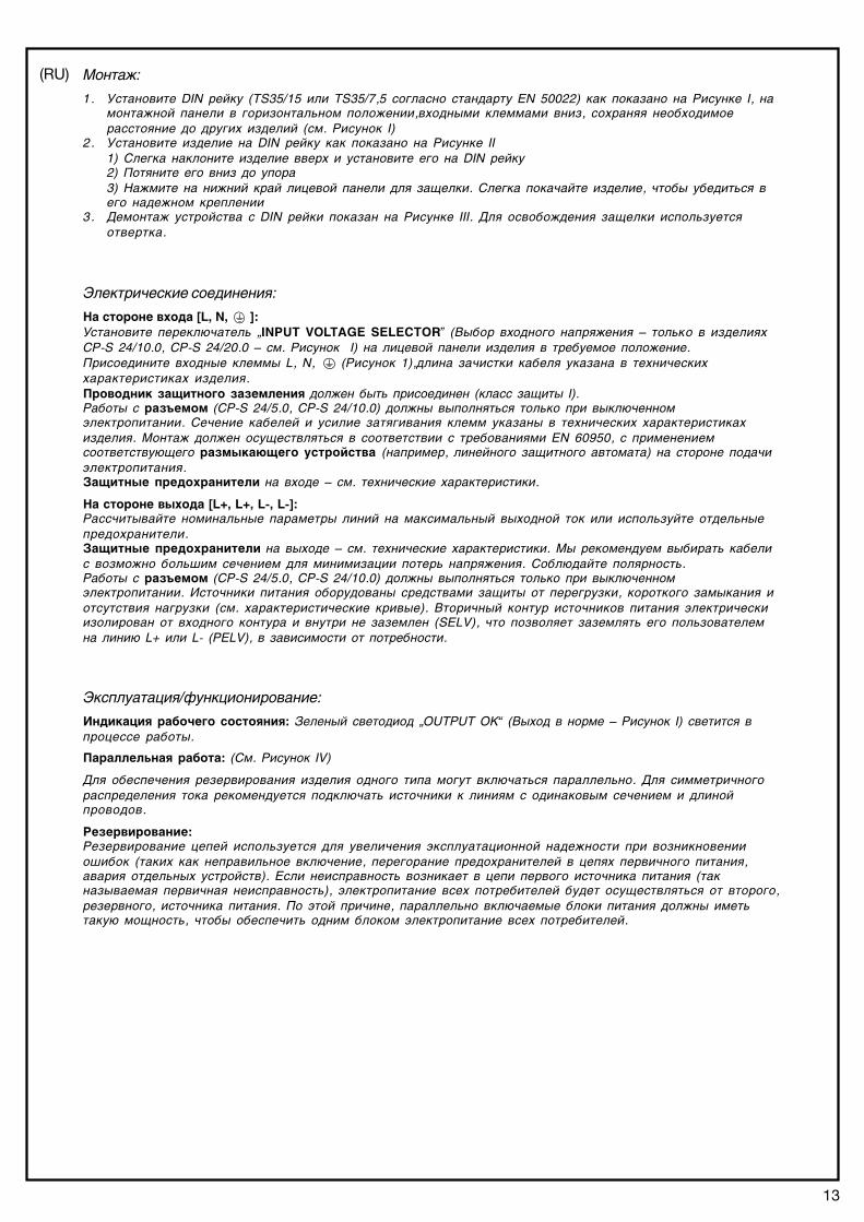
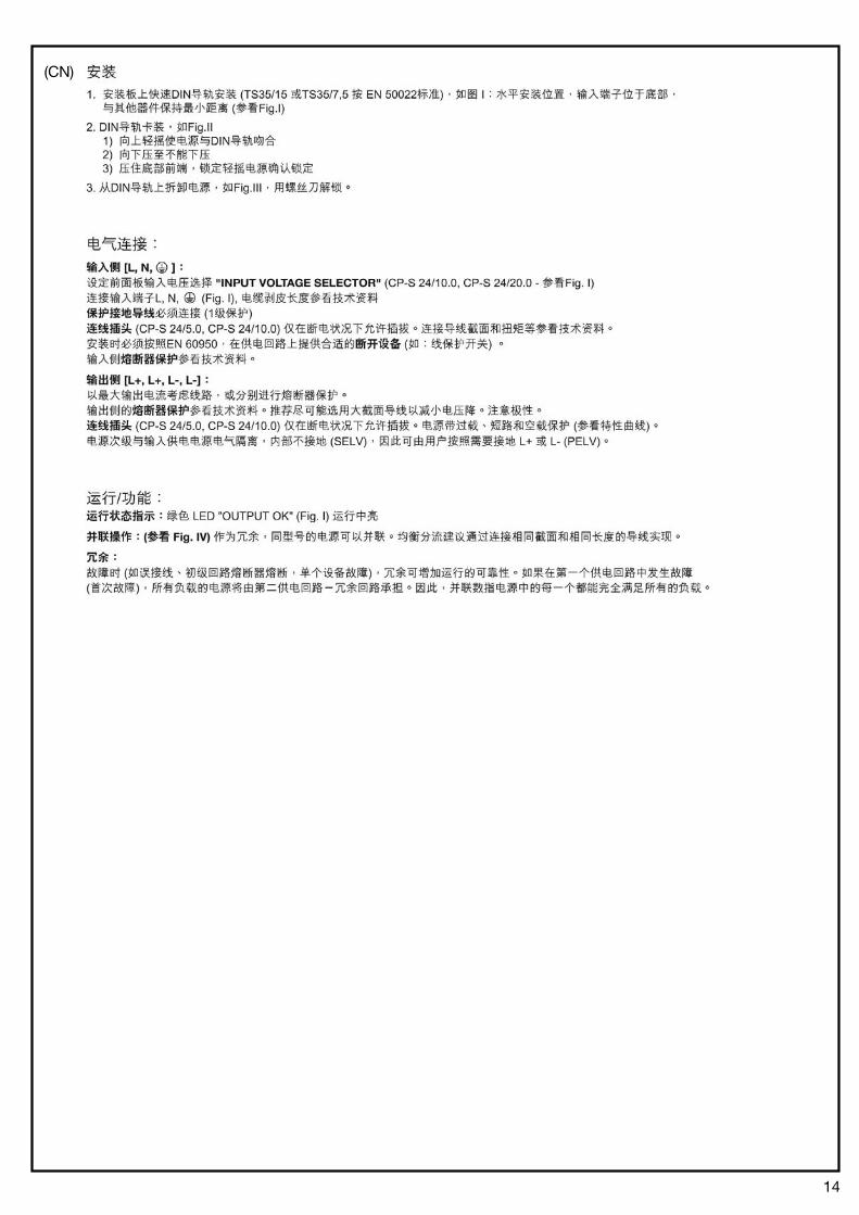
1. Установите DIN рейку (TS35/15 или TS35/7,5 согласно стандарту EN 50022) как показано на Рисунке I, намонтажной панели в горизонтальном положении,входными клеммами вниз, сохраняя необходимоерасстояние до других изделий (см. Рисунок I)
2. Установите изделие на DIN рейку как показано на Рисунке II1) Слегка наклоните изделие вверх и установите его на DIN рейку2) Потяните его вниз до упора3) Нажмите на нижний край лицевой панели для защелки. Слегка покачайте изделие, чтобы убедиться вего надежном креплении
3. Демонтаж устройства с DIN рейки показан на Рисунке III. Для освобождения защелки используетсяотвертка.
Электрические соединения:
На стороне входа [L, N, ]:Установите переключатель „INPUT VOLTAGE SELECTOR” (Выбор входного напряжения – только в изделияхCP*S 24/10.0, CP*S 24/20.0 – см. Рисунок I) на лицевой панели изделия в требуемое положение.Присоедините входные клеммы L, N, (Рисунок 1),длина зачистки кабеля указана в техническиххарактеристиках изделия.Проводник защитного заземления должен быть присоединен (класс защиты I).Работы с разъемом (CP*S 24/5.0, CP*S 24/10.0) должны выполняться только при выключенномэлектропитании. Сечение кабелей и усилие затягивания клемм указаны в технических характеристикахизделия. Монтаж должен осуществляться в соответствии с требованиями EN 60950, с применениемсоответствующего размыкающего устройства (например, линейного защитного автомата) на стороне подачиэлектропитания.Защитные предохранители на входе – см. технические характеристики.
На стороне выхода [L+, L+, L�, L�]:Рассчитывайте номинальные параметры линий на максимальный выходной ток или используйте отдельныепредохранители.Защитные предохранители на выходе – см. технические характеристики. Мы рекомендуем выбирать кабелис возможно большим сечением для минимизации потерь напряжения. Соблюдайте полярность.Работы с разъемом (CP*S 24/5.0, CP*S 24/10.0) должны выполняться только при выключенномэлектропитании. Источники питания оборудованы средствами защиты от перегрузки, короткого замыкания иотсутствия нагрузки (см. характеристические кривые). Вторичный контур источников питания электрическиизолирован от входного контура и внутри не заземлен (SELV), что позволяет заземлять его пользователемна линию L+ или L* (PELV), в зависимости от потребности.
Эксплуатация/функционирование:
Индикация рабочего состояния: Зеленый светодиод „OUTPUT OK“ (Выход в норме – Рисунок I) светится впроцессе работы.
Параллельная работа: (См. Рисунок IV)
Для обеспечения резервирования изделия одного типа могут включаться параллельно. Для симметричногораспределения тока рекомендуется подключать источники к линиям с одинаковым сечением и длинойпроводов.
Резервирование:Резервирование цепей используется для увеличения эксплуатационной надежности при возникновенииошибок (таких как неправильное включение, перегорание предохранителей в цепях первичного питания,авария отдельных устройств). Если неисправность возникает в цепи первого источника питания (такназываемая первичная неисправность), электропитание всех потребителей будет осуществляться от второго,резервного, источника питания. По этой причине, параллельно включаемые блоки питания должны иметьтакую мощность, чтобы обеспечить одним блоком электропитание всех потребителей.
(RU)
14
(CN)
15
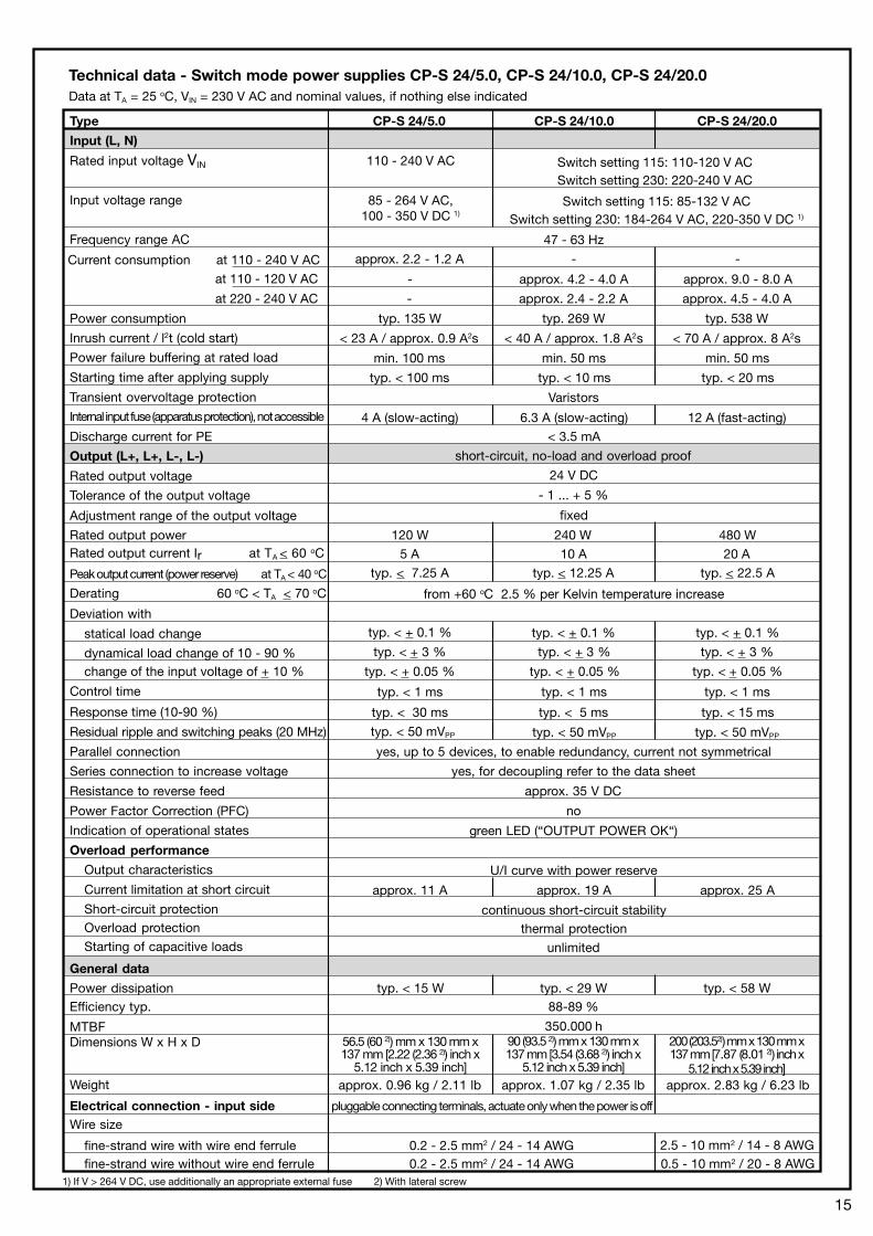
Technical data - Switch mode power supplies CP-S 24/5.0, CP-S 24/10.0, CP-S 24/20.0Data at TA = 25 oC, VIN = 230 V AC and nominal values, if nothing else indicated
General data
Power dissipationEfficiency typ.
MTBFDimensions W x H x D
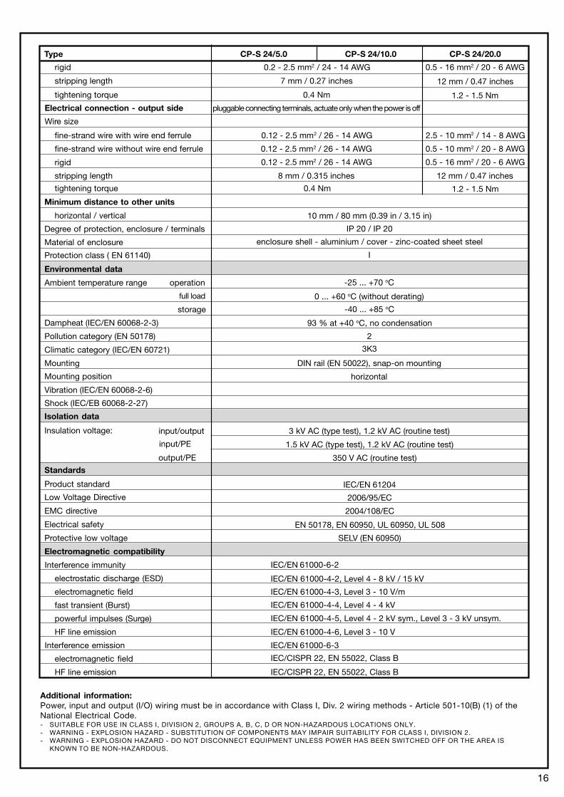
Electrical connection - input sideWire size
fine-strand wire with wire end ferrulefine-strand wire without wire end ferrule
typ. < 29 Wtyp. < 15 W typ. < 58 W88-89 %
350.000 h
pluggable connecting terminals, actuate only when the power is off
0.2 - 2.5 mm2 / 24 - 14 AWG0.2 - 2.5 mm2 / 24 - 14 AWG
2.5 - 10 mm2 / 14 - 8 AWG0.5 - 10 mm2 / 20 - 8 AWG
Type CP-S 24/5.0 CP-S 24/10.0 CP-S 24/20.0
Input (L, N)
Rated input voltage VIN 110 - 240 V AC
Input voltage range
Frequency range AC
Current consumption at 110 - 240 V AC
Power consumption
Inrush current / l2t (cold start)
Power failure buffering at rated load
Starting time after applying supply
Transient overvoltage protection
Internal input fuse (apparatus protection), not accessible
Discharge current for PE
Output (L+, L+, L-, L-)
Rated output voltage
Tolerance of the output voltage
Adjustment range of the output voltage
Rated output powerRated output current Ir at TA < 60 oC
Peak output current (power reserve) at TA < 40 oC
Derating 60 oC < TA < 70 oC
Deviation with
statical load change
dynamical load change of 10 - 90 %
Control time
change of the input voltage of + 10 %
Response time (10-90 %)
Residual ripple and switching peaks (20 MHz)
Parallel connection
Series connection to increase voltage
Resistance to reverse feed
Power Factor Correction (PFC)
Indication of operational states
Overload performance
Output characteristics
Current limitation at short circuit
Short-circuit protection
85 - 264 V AC,100 - 350 V DC 1)
47 - 63 Hz
approx. 2.2 - 1.2 A
typ. 135 W typ. 269 W typ. 538 W
< 23 A / approx. 0.9 A2s < 40 A / approx. 1.8 A2s < 70 A / approx. 8 A2s
min. 100 ms min. 50 ms min. 50 ms
Varistors
4 A (slow-acting) 6.3 A (slow-acting) 12 A (fast-acting)
< 3.5 mA
typ. < 100 ms typ. < 10 ms typ. < 20 ms
short-circuit, no-load and overload proof
24 V DC
- 1 ... + 5 %
fixed
240 W120 W 480 W
10 A5 A 20 A
typ. < 12.25 Atyp. < 7.25 A
from +60 oC 2.5 % per Kelvin temperature increase
typ. < + 0.1 %
typ. < + 3 %
typ. < 1 ms
typ. < + 0.05 %
typ. < 30 ms
yes, up to 5 devices, to enable redundancy, current not symmetrical
yes, for decoupling refer to the data sheet
approx. 35 V DC
no
green LED (“OUTPUT POWER OK“)
U/I curve with power reserve
approx. 19 A
continuous short-circuit stability
approx. 11 A approx. 25 A
typ. < + 0.1 %
typ. < + 3 %
typ. < 1 ms
typ. < + 0.05 %
typ. < 5 ms
typ. < 50 mVPP
Overload protection thermal protectionStarting of capacitive loads unlimited
Weight approx. 1.07 kg / 2.35 lbapprox. 0.96 kg / 2.11 lb approx. 2.83 kg / 6.23 lb
Switch setting 115: 110-120 V ACSwitch setting 230: 220-240 V AC
Switch setting 115: 85-132 V ACSwitch setting 230: 184-264 V AC, 220-350 V DC 1)
typ. < 22.5 A
typ. < + 0.1 %
typ. < + 3 %
typ. < 1 ms
typ. < + 0.05 %
typ. < 15 ms
typ. < 50 mVPP
-
-
-
approx. 4.2 - 4.0 A
approx. 2.4 - 2.2 A
-
approx. 9.0 - 8.0 A
approx. 4.5 - 4.0 A
at 110 - 120 V AC
at 220 - 240 V AC
1) If V > 264 V DC, use additionally an appropriate external fuse 2) With lateral screw
90 (93.5 2)) mm x 130 mm x137 mm [3.54 (3.68 2)) inch x
5.12 inch x 5.39 inch]
56.5 (60 2)) mm x 130 mm x137 mm [2.22 (2.36 2)) inch x
5.12 inch x 5.39 inch]
200 (203.52)) mm x 130 mm x137 mm [7.87 (8.01 2)) inch x
5.12 inch x 5.39 inch]
typ. < 50 mVPP
16
fine-strand wire with wire end ferrule
fine-strand wire without wire end ferrule
rigid
stripping length
tightening torque
Minimum distance to other units
horizontal / vertical
Degree of protection, enclosure / terminals
Material of enclosure
Protection class ( EN 61140)
Environmental data
Ambient temperature range operation
full load
storage
Dampheat (IEC/EN 60068-2-3)
Pollution category (EN 50178)
Climatic category (IEC/EN 60721)
Mounting
Mounting position
Vibration (IEC/EN 60068-2-6)
Shock (IEC/EB 60068-2-27)
Isolation data
Insulation voltage:
input/PE
Standards
Product standard
Electrical safety
Protective low voltage
Electromagnetic compatibility
Interference immunity
electrostatic discharge (ESD)
electromagnetic field
fast transient (Burst)
powerful impulses (Surge)
HF line emission
Interference emission
electromagnetic field
HF line emission
Electrical connection - output side
Wire size
pluggable connecting terminals, actuate only when the power is off
0.12 - 2.5 mm2 / 26 - 14 AWG
0.12 - 2.5 mm2 / 26 - 14 AWG
0.12 - 2.5 mm2 / 26 - 14 AWG
8 mm / 0.315 inches
0.4 Nm
2.5 - 10 mm2 / 14 - 8 AWG
0.5 - 10 mm2 / 20 - 8 AWG
0.5 - 16 mm2 / 20 - 6 AWG
12 mm / 0.47 inches
1.2 - 1.5 Nm
10 mm / 80 mm (0.39 in / 3.15 in)
IP 20 / IP 20
enclosure shell - aluminium / cover - zinc-coated sheet steel
-25 ... +70 oC
0 ... +60 oC (without derating)
-40 ... +85 oC
93 % at +40 oC, no condensation
2
DIN rail (EN 50022), snap-on mounting
horizontal
1.5 kV AC (type test), 1.2 kV AC (routine test)
350 V AC (routine test)
IEC/EN 61204
EN 50178, EN 60950, UL 60950, UL 508
SELV (EN 60950)
IEC/EN 61000-6-2
IEC/EN 61000-4-2, Level 4 - 8 kV / 15 kV
IEC/EN 61000-4-3, Level 3 - 10 V/m
IEC/EN 61000-4-4, Level 4 - 4 kV
IEC/EN 61000-4-5, Level 4 - 2 kV sym., Level 3 - 3 kV unsym.
IEC/EN 61000-4-6, Level 3 - 10 V
IEC/EN 61000-6-3
3 kV AC (type test), 1.2 kV AC (routine test)
IEC/CISPR 22, EN 55022, Class B
IEC/CISPR 22, EN 55022, Class B
rigid
stripping length
tightening torque
0.2 - 2.5 mm2 / 24 - 14 AWG
7 mm / 0.27 inches
0.4 Nm
0.5 - 16 mm2 / 20 - 6 AWG
12 mm / 0.47 inches
1.2 - 1.5 Nm
I
3K3
EMC directive 2004/108/EC
Low Voltage Directive 2006/95/EC
Type CP-S 24/5.0 CP-S 24/10.0 CP-S 24/20.0
output/PE
input/output
Additional information:Power, input and output (I/O) wiring must be in accordance with Class I, Div. 2 wiring methods - Article 501-10(B) (1) of theNational Electrical Code.- SUITABLE FOR USE IN CLASS I, DIVISION 2, GROUPS A, B, C, D OR NON-HAZARDOUS LOCATIONS ONLY.- WARNING - EXPLOSION HAZARD - SUBSTITUTION OF COMPONENTS MAY IMPAIR SUITABILITY FOR CLASS I, DIVISION 2.- WARNING - EXPLOSION HAZARD - DO NOT DISCONNECT EQUIPMENT UNLESS POWER HAS BEEN SWITCHED OFF OR THE AREA IS
KNOWN TO BE NON-HAZARDOUS.