contribution to hierarchical modeling in tunnel design ... · keywords: tunnels, hierarchical...
TRANSCRIPT

© 2019 IBRACON
Volume 12, Number 5 (October 2019) p. 1205 – 1219 • ISSN 1983-4195http://dx.doi.org/10.1590/S1983-41952019000500012
Contribution to hierarchical modeling in tunnel design practice
Contribuição à modelagem hierárquica no projeto de túneis
a Universidade de São Paulo, Escola Politécnica, Departamento de Engenharia de Estruturas e Geotécnica, São Paulo, SP, Brasil;b dMBB Projetos Ltda, São Paulo, SP, Brasil;c EGT Engenharia, São Paulo, SP, Brasil.
Received: 29 Oct 2018 • Accepted: 14 Jan 2019 • Available Online:
This is an open-access article distributed under the terms of the Creative Commons Attribution License
B. S. DZIALOSZYNSKI a,b
[email protected]://orcid.org/0000-0002-7881-5141
F. R. STUCCHI a,c
[email protected]://orcid.org/0000-0003-4149-0985
Abstract
Resumo
This work presents a comparative analysis between two model hierarchies commonly applied in tunnel structural design: continuum ground mod-els and bedded-beam models. Firstly, the main characteristics of each model and the interfaces between them are discussed. Based on those evaluations a simple procedure is proposed for determining the bedded-beam model imposed loads which lead to results compatible to those of a given continuum model. Said procedure is then explored to estimate simplified compatibilization loads for basic and illustrative cases, where a reasonable compatibilization was achieved for a relatively simple applied load.
Keywords: tunnels, hierarchical modelling, numerical modeling.
Esse trabalho apresenta uma análise comparativa entre duas hierarquias de modelos comumente aplicadas no projeto estrutural de túneis: modelos de maciço contínuo e de anel sobre apoios. Primeiramente, as principais características de cada modelo e as interfaces entre ambos são discutidas. Baseado em tais avaliações um procedimento simples é proposto para determinar as cargas impostas ao modelo de anel sobre apoios que levam a resultados compatíveis àqueles de um dado modelo de maciço contínuo. Tal procedimento é então explorado para estimar carregamentos de compatibilização simplificados para casos básicos e ilustrativos, onde uma compatibilização razoável foi atingida para um carregamento relativamente simples.
Palavras-chave: túneis, modelagem hierárquica, modelagem numérica.

1206 IBRACON Structures and Materials Journal • 2019 • vol. 12 • nº 5
Contribution to hierarchical modeling in tunnel design practice
1. Introduction
Civil engineering applies mathematical models to simulate and solve physical problems of complex nature. By definition, models idealize and simplify reality, in order to be a viable and practical tool for the analysis and design of civil structures.Due to its complex nature, the use of various model hierarchies and methods for the design and analysis of tunnels is common. Indeed, the International Tunneling Association [1], in its guidelines for the design of tunnels highlights 4 major groups of methods for the struc-tural modeling and design of tunnels, namely: continuum models (or discontinuum, for rock massifs); bedded-beam models (or action-reaction); empirical approaches; and the observational method.The continuum models usually allow for a more sophisticated anal-ysis, but higher model sophistication leads to higher volume and complexity of input data to estimate and output data to interpret. Thus, a growing complexity of the continuum models is expected to come at the tradeoff of costlier and lengthier processes, which may be more susceptible to error, due to occasional less intuitive model results.Indeed, for the design practice of tunnels, it is of great value to apply lower hierarchical for simple and quick evaluation of physical behav-iors, the validation of higher hierarchy models and the estimation of preliminary results in the search for effective hierarchical models (Bucalem and Bathe [2]). In extense projects, with typical, repre-sentative regions and a large number of sections to be analyzed, it may also be advantageous to directly apply lower hierarchy models, calibrated and validated by a smaller number of higher hierarchy models for each region. Bedded-beam models are highlighted as useful tools for said goal (Prado and Waimberg [3]).This paper aims at a comparative analysis between the continuum soil/rock mass models – henceforth denominated as hierarchy H1
models – and on the bedded-beam models – henceforth denomi-nated hierarchy H2 models - in the context of the analysis and design of tunnels. A procedure for a potential compatibilization of both models is proposed, in the scope of their combined used for the design. Lastly, comparative example cases are presented for the application of the models, aiming at assessing said potential, and applying the proposed procedure.
2. Interface, comparison and calibration between model hierarchies
The comparison of the results for different model hierarchies is not rare in the technical bibliography. Examples of authors which have explored it are: Duddeck and Erdmann [4], comparing traditional models, with a general and conceptual scope; der Poel, Hergarden and Dekker [5], with numerical analysis for some ground profiles; Prado and Waimberg [3], with numerical analysis to study bedded-beam load distribution for a specific case; Vu, Broere and Bosch [6], applying numerical models and field measurements to validate a new bedded-beam model proposition.Technical bibliography commonly highlights the use of bedded-beam models especially for TBM (Tunnel Boring Machine) tunnels, due to its particular geometric and construction characteristics, but there is the possibility of also modeling NATM (New Austrian Tun-neling Method) tunnels, with its due reservations and simplifications.The main difference and interface between hierarchies H1 and H2 resides in how the ground (soil or rock mass) is modeled. Figures [1] and [2] illustrate the described model hierarchies.For the hierarchy H1 ground is modeled as a deformable solid, together with the lining and support structures. The soil-structure interaction will result from the solution of equilibrium for the com-pound structure, accounting for the compatibility of deformations between elements. The engineer estimates the parameters and
Figure 1Hierarchy H1 model schematic view

1207IBRACON Structures and Materials Journal • 2019 • vol. 12 • nº 5
B. S. DZIALOSZYNSKI | F. R. STUCCHI
constitutive behavior for the soil/rock mass and support structures, and soil-structure interaction will derive from such estimations. Outputs related to stress, strain and displacement fields within the soil/rock mass may be computed.For the hierarchy H2 ground is modeled simply by loads and links/“springs” applied to the structure. The engineer directly estimates an imposed load and the constitutive behavior of the links/“springs”. The soil-structure interaction is thusly reflected sim-ply by the conjunction of imposed loads and link/“spring” reactions, and results regarding ground response are limited.When applying hierarchy H2, a distinction between an ‘applied ac-tion’ part and a ‘link/“spring” reaction’ part of the soil structure-in-teraction is necessarily made. Despite being relatively intuitive, this distinction is arbitrary. For hierarchy H1 such distinction is not made, drawing it conceptually closer to the actual physical problem.Indeed, for an ideal compatibilization, the multiple physical be-haviors of the soil/rock simulated in hierarchy H1 would have to be totally translated only in the estimation of applied loads and link/“spring” constitutive behavior for hierarchy H2.In the same way that the accuracy for hierarchy H1 models depends on the representativeness of the estimated parameters and constitu-tive behaviors, the accuracy of hierarchy H2 models depends on the quality of the load and link/“spring” stiffness estimations.On the one hand, the input data for hierarchy H1 is usually com-posed of design and material parameters, imposed as design cri-teria or estimated from laboratory and field measurements. On the other hand, for hierarchy H2 the input data normally cannot be readily measured or imposed, especially before the actual con-struction works. Thus, usually said inputs are estimated by the engineer through a number of methods, commonly of empirical, approximate and simplified nature.Some examples of estimations for the hierarchy H2 imposed loads are described in Mashimo and Ishimura [7], Duddeck and Erdman
[4], Martinek and Winter [8]; and for links/“springs” constitutive be-havior in Duddeck and Erdmann [4], Martinek and Winter [8], Or-este [9], Do et al. [10], Vu, Broere and Bosch [6].
3. “Ideal” hierarchical model compatibilization
For the study and determination of approximate imposed loads which would lead to a reasonable compatibilization between model hierarchies it of interest to determine what would be the exact load to be imposed to hierarchy H2 which would lead to a solution iden-tical to that of hierarchy H1. The practical determination of such load shall be discussed hereafter.
3.1 Concept
Consider a given physical problem of the static equilibrium of a tun-nel excavation where one aims at obtaining an identical response for lining loads, for models of hierarchy H1 and H2. For both hier-archies, an approximation by the finite elements method with small displacements hypothesis is proposed. It is assumed, for simplic-ity in this presentation, that no interface elements are applied, so that ground and lining elements share mesh nodes, and are thusly rigidly linked.The solution of the tunnel excavation physical problem, when modeled through hierarchy H1 usually applies successive calcula-tion stages which reflect the actual construction sequence, with inclusion and exclusion of finite elements mesh sectors. For ex-ample, it is common to initially apply a partial excavation stress relief of the unlined crown excavation, followed by the installation of the crown’s support with additional stress relief, followed by the successive excavation and simultaneous support installation of the inverts – temporary and final – with full stress relief. Thus, let
Figure 2Hierarchy H2 model schematic view

1208 IBRACON Structures and Materials Journal • 2019 • vol. 12 • nº 5
Contribution to hierarchical modeling in tunnel design practice
un be the total accumulated nodal displacement vector for a given construction / calculation stage n:
(1)
Where ∆ui denotes the nodal displacement variation vector for a given calculation stage i.As there is the possibility of the inclusion and exclusion of mesh sectors, displacements that actually imply loads at the support for a given lining part refer only to the calculation stages where the el-ements of said lining part were active in the mesh. For example: (i) during the stress relief of the unlined crown the nodes that will inte-grate the lining elements are displaced. However, the lining is not yet activated; (ii) at the beginning of the next stage, where lining installation and an additional stress relief will be computed, nodes are already displaced, but lining loads are still null, as the sup-port was activated in the displaced configuration; (iii) only from this stage on, with active lining elements, displacements will cause lin-ing loads. Indeed, such model characteristics reflect actual physi-cal behavior, regarding the lag between stress relief, excavation advancement and primary lining installation.
Thus let unp be defined as the vector of the accumulated nodal
displacements that cause actual loading of a given lining part p for a given calculation stage n, that is:
(2)
Where t denotes the calculation stage where the lining part p is activated, and assuming that said part remains active from stages t to n. ‘Lining part’ refers, for example, to the crown, temporary invert (TI), final invert (FI), modeled by a given set of elements.Once the hierarchy H1 model is solved, un
p is known for all calcula-tion stages and lining parts. Figure [3](a) illustrates said solution, for an illustrative and simplified case of a beam fixed at both ends with a single free node and degree of freedom (nodal vectors sim-plified to scalar value).Consider another model, without the ground elements, that is, solely with the lining elements. Analogous mesh and lining part activation are modeled, but links / “springs” and self-weight that would be present in and hierarchy H2 model are not applied. By imposing in this model, stage by stage, and part by part, prescribed nodal support displacements with the respective un
p values, an
Figure 3Illustrative example of the “ideal” calibration procedure with a beam fixed at both ends. (a) Results for hierarchy H1; (b) Hierarchy H2* model for obtaining the “ideal” compatibilization nodal force components; (c) Hierarchy H2 model with “ideal” compatibilization load; (d) Illustrative model without self-weight and without imposed links/“springs”, with the computation of the equivalent total nodal force
a
c
b
d

1209IBRACON Structures and Materials Journal • 2019 • vol. 12 • nº 5
B. S. DZIALOSZYNSKI | F. R. STUCCHI
identical solution to that of hierarchy H1 is obtained, regarding the lining loads. Figure [3](d) illustrates said model for the aforemen-tioned illustrative case.Let fn
H1 be the vector with the respective prescribed displacement support reactions for each node in the model. In a more intuitive fashion, one may obtain the same identical solution to that of hier-archy H1 by applying to the discussed model, stage by stage, fn
H1 as nodal forces or a kinematically equivalent distributed load.For hierarchy H2 models, however, the nodal force vector for each stage fn
H2, for usual cases, has 3 components of the total nodal loading, namely: imposed loading due to the soil/rock mass (ground load), fn
s; imposed loading due to self-weight, fnw and; re-
actions at links / “springs”, fnl.
The said “ideal” compatibilization, with identical solution, would be obtained when fn
H2 loads are applied stage by stage, with:
(3)
Or a kinematically equivalent load.The components fn
s and fnw are totally imposed by the engineer,
and are known previous to the model solution, reflecting a load-ing “before deformation”. However, the fn
l component depends not only on the imposed constitutive behavior and parameters, but also on the un
p displacements, thus being known only after the model solution. Indeed, as a component of fn
H2 depends on the displacements, its imposition in the hierarchy H2 model for “ideal” compatibilization is not totally immediate.
3.2 Practical procedure for computing the “ideal” compatibilization load
A practical procedure is proposed for computing the components of the “ideal” compatibilization load. The procedure is of simple im-plementation in usual computational tools available in the market. The procedure stages are explained in a general manner but figure [3] shall be illustratively referenced for the simplified example of a beam fixed at both ends with a single free node and degree of freedom. Procedure stages are as follows:1. For the calibration it is assumed that the hierarchy H1 model
has been solved, and unp is known for any relevant n and p
(see figure [3] (a)). The aim is, thus, to determine the individual values of fn
w, fns and fn
l to be applied in the hierarchy H2 to model for “ideal” compatibilization with such known result.
2. The self-weigh component fnw is obtained directly form the tun-
nel lining properties.3. A constitutive behavior is defined and imposed for the links /
“springs” to be applied in the hierarchy H2 model. The pro-cedure shall result in compatibilization loads for such defined links, regardless of its representativity of the actual physical behavior. However, more realistic and intuitive compatibiliza-tion loads should normally result for better estimations of link / “spring” behavior.
4. An auxiliary model is applied, henceforth referred to as of hi-erarchy H2*. This model is defined as a bedded-beam model with the beam lining elements mesh and calculation stages analogues to those of the hierarchy H1 model. For such model, the self-weight component fn
w stipulated in procedure stage 2 is imposed, as well as the links / “springs” stipulated in proce-
dure stage 3, both identical for hierarchy H2 and H2* models. However, for this model, the nodal forces due to ground load-ing fn
s are not imposed, applying in their place nodal support displacements with the values of un
p, obtained for hierarchy H1 (see figure [3] (b)). In such hierarchy H2* model the ground component of the nodal forces fn
s does not exist, figuring in its place a component due to the reactions in the supports with imposed displacements, fn
r. Thus for the “ideal” compatibiliza-tion of the hierarchy H2* model:
(4)
5. Solving the hierarchy H2* model of procedure stage 4 an iden-tical solution to that of hierarchy H1 is obtained, that is, total nodal forces are in tune with equation [4].
6. As the stage by stage nodal displacements are, by imposition, identical to those of the hierarchy H1 solution, the reaction in the imposed links / “springs” shall be fn
l, identical for hierarchy H2 and H2* in the “ideal” compatibilization.
7. As for the “ideal” compatibilization of hierarchy H2 equation [3] is valid and for the “ideal” compatibilization of hierarchy H2* equation [4] is valid:
(5)
That is, the reactions in the supports with imposed settle-ments in hierarchy H2*, fn
r, have identical values to those of the ground component of the “ideal” compatibilization load of hierarchy H2, fn
s.8. In this stage the individual values of fn
w, fns and fn
l are already known. Thus, the imposition of fn
w and fns for each calculation
stage in the hierarchy H2 model with analogous mesh and analogous link / “springs” as stipulated in procedure stage 3 shall lead to a solution identical to that of hierarchy H1 (see figure [3] (c)). The reactions in the imposed links/“springs” shall be fn
l for the computed solution.It is evident that this methodology in itself is of little value for direct use in the actual design practice, as it is a totally imposed calibra-tion, where it is necessary to know beforehand the solution for hier-archy H1. However, its application allows one to directly obtain, for hierarchy H2, and a given set of estimated links/“springs”, the load that leads to the same response as hierarchy H1. Its application in various cases, thus, may allow the investigation of patterns, rules and correlations that lead to a reasonable calibration of model hi-erarchies for typical cases.
4. Case examples
In order to illustrate and explore the discussed concepts, their ap-plication to a set of cases of the hierarchical modelling of a physical problem is proposed.
4.1 Physical problem
The loads in the primary support of a tunnel to be driven through a hard tertiary clay are to be evaluated. The cross section of the tunnel consists of a 4-arch ring and is symmetrical to the verti-cal central axis. Tunnel cover is of 30m and a very stiff material,

1210 IBRACON Structures and Materials Journal • 2019 • vol. 12 • nº 5
Contribution to hierarchical modeling in tunnel design practice
assumed as totally rigid is identified 10m below the FI of the tun-nel. Primary support is prescribed as a 25cm thick shotcrete lining, with stiffness estimated at 10GPa for the ages to be modelled. The groundwater level is assumed to be totally lowered in the regions relevant to the structure. Figure [4] illustrates schematically the de-scribed physical problem.
4.2 Hierarchy H1
For the modelling and solution of the case examples in hierarchy H1 the finite elements method was applied, utilizing the software Midas GTS NX. The physical problem was simplified to a plane strain bidimensional model, and took advantage of the symmetry along the vertical central axis of the tunnel.The soil mass was modeled with 3-nodded triangle elements with homogeneous, isotropic linear elastic, perfectly plastic behavior, with Mohr-Coulomb yielding criteria. It is important to highlight that such hypothesis represents a great simplification of the actual constitutive behavior of the material, even though it is commonly applied in design practice. Nonetheless, for the purposes of this work the simplification is considered reasonable, with the acknowl-edgement that more sophisticated constitutive models could lead to different results.
The tunnel lining was modeled with 2-nodded Bernoulli-Euler beam elements. That is, potential effects of stresses acting in the lining out of the modelled plan are neglected. No interface ele-ments between ground and structure were applied, therefore being assumed that both are rigidly linked.Table [1] presents the estimated parameters for the hard tertiary clay.
4.3 Hierarchy H2
The modelling and solution of the hierarchy H2 models also ap-plied the finite elements method with aid of the software Midas GTS NX. The lining was modelled with elements and mesh ana-logues to those of hierarchy H1.The links/“spings” that represent ground’s soil-structure interface reaction in the normal direction were discretely modelled, node by node, with linear elastic behavior for compression and null reaction for tension. The stiffness of such links was estimated according to the following equations for the modulus of subgrade reaction kr, as proposed by Martinek e Winter [8]:
(6)
(7)
Where E and υ are the modulus of elasticity and Poisson’s ratio for the soil, assumed to be isotropic and linear elastic. R denotes the radius of the tunnel. Naturally, such relationships were origi-nally estimated for a circular lining geometry, being utilized in an adapted fashion for the more complex geometry of the modelled tunnel. For each cross section arch, the modulus of subgrade reac-tion was duly adjusted.The link reactions in tangential direction were also discretely mod-eled, with linear elastic behavior. Various authors, like for example Vu, Broere and Bosch [6] or Plizzari and Tibert [11] consider the following relationship between the normal kr and tangential ks link stiffness to be reasonable:
(8)
In the bibliography such relationship is many times associated to more complex constitutive behaviors for the links/“springs” and/or to TBM tunnels, with circular geometry. Still, acknowledging po-tential limitations of its use, for the present study, the relationship was adopted.The imposed loads were determined in depending on the stud-ied case.
4.4 Case A – Single stage construction
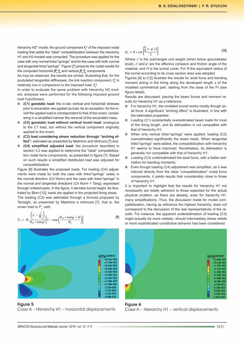
For this evaluation the problem was modelled without the consid-eration of construction stages. That is, for the hierarchy H1 only two calculation stages are modeled: (i)stress state initialization, according to the coefficient of lateral earth pressure, K0 and; (ii) excavation and lining installation for crown and FI with total and simultaneous stress relief.Figures [5] and [6] present the results for horizontal and vertical displacements for hierarchy H1, respectively.Following the procedure detailed in section 3.2, and using the auxiliary
Table 1Estimated ground parameters
Parameter Symbol ValueUnit weight γ 20 kN/m3
Angle of friction φ' 22ºCohesion c' 75 kPa
Elasticity modulus E 100 MPaPoisson’s ratio υ 0.3
Coefficient of lateral earth pressure K0 0.8
Figure 4Physical problem schematic view
1211IBRACON Structures and Materials Journal • 2019 • vol. 12 • nº 5
B. S. DZIALOSZYNSKI | F. R. STUCCHI
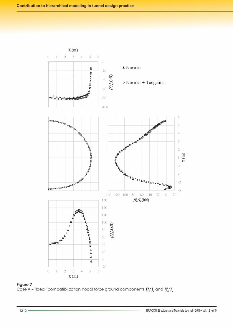
hierarchy H2* model, the ground component fns of the imposed nodal
loading that yields the “ideal” compatibilization between the hierarchy H1 and H2 models was computed. The procedure was applied for the case with only normal links/“springs” and for the case with both normal and tangential links/“springs”. Figure [7] presents the nodal results for the computed horizontal [fn
s]x and vertical [fns]y components.
As may be observed, the results are similar, illustrating that, for the postulated tangential stiffnesses, the link reaction component, fn
l is relatively low in comparison to the imposed load, fn
s.In order to evaluate the same problem with hierarchy H2 mod-els, analyses were performed for the following imposed ground load hypotheses:n (C1) geostatic load: the in-situ vertical and horizontal stresses
prior to excavation are applied as load. As an exception, for the in-vert the applied load is correspondent to that of the crown, consid-ering in a simplified manner the removal of the excavated mass;
n (C2) geostatic load without vertical invert load: analogous to the C1 load, but without the vertical component originally applied to the invert;
n (C3) load considering stress reduction through “arching ef-fect”: estimated as presented by Mashimo and Ishimura [7] and;
n (C4) simplified adjusted load: the procedure described in section 3.2 was applied to determine the “ideal” compatibiliza-tion nodal force components, as presented in figure [7]. Based on such results a simplified distributed load was adjusted for compatibilization.
Figure [8] illustrates the proposed loads. For loading (C4) adjust-ments were made for both the case with links/“springs” solely in the normal direction (C4 Norm) and the case with links/“springs” in the normal and tangential directions (C4 Norm + Tang), expressed through ordered pairs. In the figure, h denotes tunnel height. As illus-trated by Blom [12], loads are applied in the projected lining areas.The loading (C3) was estimated through a formula proposed by Terzaghi, as presented by Mashimo e Ishimura [7], that is, the crown load is Pv, with:
(9)
(10)
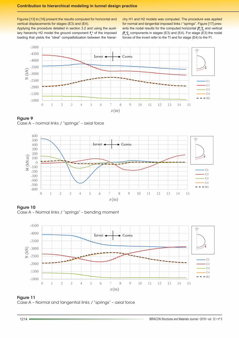
Where γ' is the submerged unit weight (when below groundwater level), c' and φ' are the effective cohesion and friction angle of the material, and H is the tunnel cover. For R the equivalent radius of the tunnel according to its cross section area was adopted.Figures [9] to [12] illustrate the results for axial force and bending moment acting in the lining along the developed length s of the modeled symmetrical part, starting from the base of the FI (see figure detail).Results are discussed, placing the beam forces and moment re-sults for hierarchy H1 as a reference:n For hierarchy H1, the modeled tunnel works mostly though ax-
ial force. A significant “arching effect” is illustrated, in line with the estimated properties;
n Loading (C1) substantially overestimated beam loads for most of the lining length, and its delineation is not compatible with that of hierarchy H1;
n When only normal links/“springs” were applied, loading (C2) overestimated significantly the beam loads. When tangential links/“springs” were added, the compatibilization with hierarchy H1 seems to have improved. Nonetheless, its delineation is generally nor compatible with that of hierarchy H1;
n Loading (C3) underestimated the axial force, with a better esti-mation for bending moments;
n Even though loading (C4) adjustment was simplified, as it was inferred directly from the ideal “compatibilization” nodal force components, it yields results that considerably close to those of hierarchy H1.
It is important to highlight that the results for hierarchy H1 not necessarily are totally adherent to those expected for the actual physical problem, as there are already, even for hierarchy H1, many simplifications. Thus, the discussion made for model com-patibilization, having as reference the highest hierarchy, does not correspond to the discussion of the real representativity of the re-sults. For instance, the apparent underestimation of loading (C3) might actually be more realistic, should intermediary stress reliefs or more sophisticated constitutive behavior had been considered.
Figure 5Case A – Hierarchy H1 – horizontal displacements
Figure 6Case A – Hierarchy H1 – vertical displacements
1212 IBRACON Structures and Materials Journal • 2019 • vol. 12 • nº 5
Contribution to hierarchical modeling in tunnel design practice
Figure 7Case A – “Ideal” compatibilization nodal force ground components [fn
s]x and [fns]y

1213IBRACON Structures and Materials Journal • 2019 • vol. 12 • nº 5
B. S. DZIALOSZYNSKI | F. R. STUCCHI
4.5 Case B – multiple stage construction
This case was aimed at exploring a commonly applied procedure for modeling NATM tunnels though hierarchy H1. For hierarchy H1 the following calculation stages were modeled:n (E1) Stress state initialization according to K0;n (E2) Excavation of crown and TI, with 50% stress relief;n (E3) Lining installation for crown and TI, with the remaining
50% stress relief;n (E4) Excavation and lining installation for the FI, with immedi-
ate stress relief.It should be noted that a simplification was made, modeling the advancement of excavation and lining installation for the TI simul-taneously to the crown. Such hypothesis is considered reasonable for the present scope, assuming the advancements are made with small lags.
Figure 8Case A – Hierarchy H2 – imposed loads
1214 IBRACON Structures and Materials Journal • 2019 • vol. 12 • nº 5
Contribution to hierarchical modeling in tunnel design practice
Figures [13] to [16] present the results computed for horizontal and vertical displacements for stages (E3) and (E4).Applying the procedure detailed in section 3.2 and using the auxil-iary hierarchy H2 model the ground component fn
s of the imposed loading that yields the “ideal” compatibilization between the hierar-
chy H1 and H2 models was computed. The procedure was applied for normal and tangential imposed links / “springs”. Figure [17] pres-ents the nodal results for the computed horizontal [fn
s]x and vertical [fn
s]y components in stages (E3) and (E4). For stage (E3) the nodal forces of the invert refer to the TI and for stage (E4) to the FI.
Figure 9Case A – normal links / “springs” – axial force
Figure 10Case A – Normal links / “springs” – bending moment
Figure 11Case A – Normal and tangential links / “springs” – axial force

1215IBRACON Structures and Materials Journal • 2019 • vol. 12 • nº 5
B. S. DZIALOSZYNSKI | F. R. STUCCHI
The occurrence of sharper variations may be observed in the tran-sition from crown to invert. These occurrences may be related to the sharp tangency discontinuity in stage (E3) between crown and
TI; to the considered constructions stages, deactivating TI and activating FI; and also to yielding in the region. Such phenomena also deviate from the hypotheses applied to link/“spring” behavior estimation
Figure 13Case B – Hierarchy H1 – Stage (E3) – horizontal displacements
Figure 14Case B – Hierarchy H1 – Stage (E3) – vertical displacements
Figure 15Case B – Hierarchy H1 – Stage (E4) – horizontal displacements
Figure 16Case B – Hierarchy H1 – Stage (E4) – vertical displacements
Figure 12Case A – Normal and tangential links / “springs” – bending moment

1216 IBRACON Structures and Materials Journal • 2019 • vol. 12 • nº 5
Contribution to hierarchical modeling in tunnel design practice
in hierarchy H2, hindering an intuitive compatibilization. For example, ver-tical positive loads are verified in the crown, and negative vertical loads are verified in the invert, intuitively corresponding to reaction, not loading.
It may also be noted that loads in part of the TI are low for stage (E3), indicating that during the partial stress relief in stage (E2) a major fraction of the stresses in the region were significantly reduced.
Figure 17Case B – “Ideal” compatibilization nodal force ground components [fn
s]x and [fns]y

1217IBRACON Structures and Materials Journal • 2019 • vol. 12 • nº 5
B. S. DZIALOSZYNSKI | F. R. STUCCHI
Figure 18Case B – Hierarchy H2 – imposed loads
Figure 19Case B – Stage (E3) – axial force
Figure 20Case B – Stage (E3) – bending moment

1218 IBRACON Structures and Materials Journal • 2019 • vol. 12 • nº 5
Contribution to hierarchical modeling in tunnel design practice
In line with what was performed for loading (C4) in Case A, a sim-plified load was adjusted according to the nodal component fn
s of the “ideal’ compatibilization nodal forces obtained with the aid of an hierarchy H2* model, from figure [17]. Figure [18] illustrates the adjusted loads, which were applied to a hierarchy H2 model with both normal and tangential links / “springs”.Figures [19] to [22] illustrate the results for axial force and bending moment acting in the lining along the developed length s of the mod-eled symmetrical part, starting from the base of the invert (temporary for stage (E3) and final for stage (E4)) (see figure detail).It may be observed that, despite a higher complexity in the “ide-al” compatibilization nodal force pattern illustrated in figure [17], it is possible to obtain reasonable adherence in the beam loads, especially axial force, maintaining a relatively simple load pat-tern. The bending moments for stage (E4) showed lower com-patibility, illustrating that as the sophistication of the hierarchy H1 model increases, the “ideal” compatibilization may be hin-dered, due phenomena less adherent to the hypotheses and
limitations of hierarchy H2. The relatively low bending moments must be highlighted, however. The imposed load could be fur-ther simplified, at the tradeoff of lower adherence, especially for bending moments.
5. Conclusions and future work
This work comparatively analyzed hierarchical models for the anal-ysis and design of tunnels. A simple procedure was proposed to directly compute an “ideal” compatibilization load between hierar-chies though nodal force components, applying the finite elements method. Said nodal loading may be utilized to estimate distributed loads for reasonable hierarchy compatibilization.The procedure was applied in simple and particular case examples to evaluate its potential, in comparison to other load estimations usual to the bibliography and design practice. For those examples the possibility of reasonable compatibilization between hierarchies with relatively simple adjusted loads was verified. The proposed
Figure 21Case B – Stage (E4) – axial force
Figure 22Case B – Stage (E4) – bending moment

1219IBRACON Structures and Materials Journal • 2019 • vol. 12 • nº 5
B. S. DZIALOSZYNSKI | F. R. STUCCHI
loads could be further simplified, with the tradeoff of less adherent beam loads, especially the bending moments.However, the simplicity and specificity of the evaluated cases must be highlighted. Indeed, the compatibilization loads were directly estimated from the higher order hierarchy results, without rules of general nature for cases where the results for the continuous ground model are not known beforehand. For the discussed proce-dures to have its potential effectively explored, a higher number of examples should be evaluated in future work, with higher sophisti-cation for the continuum ground models.
6. References
[1] International Tunneling Association - ITA. Guidelines for the Design of Tunnels. Tunnelling and underground space tech-nology, v.3, n.3, 1988; p. 237-249.
[2] BUCALEM, M.L.; BATHE, K.J. The mechanics of solids and structures - hierarchical modeling and the finite element solution. Berlin: Springer Science & Business Media, 1ed, 2011, 596 p.
[3] PRADO, F. S.; WAIMBERG, M.. A modelagem numérica da interação solo-estrutura. Concreto & Construções, ed. 84, 2016; p. 83-88.
[4] DUDDECK, H.; ERDMANN, J. Structural design models for tunnels. In: Tunnelling 82, 3rd, Brighton, 1982, Proceedings, London, 1982; p.83-91.
[5] DER POEL, J.T. Van; HERGARDEN, H.J.A.M.; DEKKER, H. R. E. Soil loads acting on shield tunnels: Comparison be-tween bedded beam model and finite element calculations. In: Tunneling. A Decade of Progress – Geodelft 1995-2005. London: Taylor & Francis, 1ed, 2006; p. 195-200.
[6] VU, M.N.; BROERE, W.; BOSCH, J.W. Structural Analysis for Shallow Tunnels in Soft Soils. International Journal of Geomechanics, v.17, n.8, 2017; p. 1-10.
[7] MASHIMO, H.; ISHIMURA, T. Evaluation of the load on shield tunnel lining in gravel. Tunnelling and underground space technology, v.18, n.2, 2003; p.233-241.
[8] MARTINEK, K.; WINTER, V.K.. Tunnelbau Unter Tage. Er-laeuterungen Zu Den Normen, Richtlinien Und Regeln. Wi-esbaden und Berlin: Bauverlag GmbH, 1ed, 1987.
[9] ORESTE, P. P. A numerical approach to the hyperstatic re-action method for the dimensioning of tunnel supports. Tun-nelling and Underground Space Technology, v.22, n.2, 2007; p. 185-205.
[10] DO, N.A.; DIAS, D.; ORESTE, P.; DJERAN-MAIGRE, I.. The behaviour of the segmental tunnel lining studied by the hy-perstatic reaction method. European Journal of Environmen-tal and Civil Engineering, v.18, n.4, 2014; p. 489-510.
[11] PLIZZARI, G.; TIBERTI, G. Steel fibers as reinforcement for precast tunnel segments. Tunnelling Underground Space Technol., v.21, n.3, 2006; pp. 438–439.
[12] BLOM, Cornelis Bernhard Marco. Design philosophy of con-crete linings for tunnels in soft soils. Delft: DUP Science, 1ed, 2002, 245 p.