brassblaster2
TRANSCRIPT
8/7/2019 BrassBlaster2
http://slidepdf.com/reader/full/brassblaster2 1/3
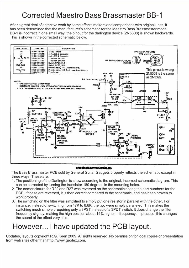
Corrected Maestro Bass Brassmaster BB-1After a great deal of detective work by some effects makers and comparisons with original units, ithas been determined that the manufacturer’s schematic for the Maestro Bass Brassmaster modelBB-1 is incorrect in one small way: the pinout for the darlington device (2N5308) is shown backwards.This is shown in the corrected schematic below.
The Bass Brassmaster PCB sold by General Guitar Gadgets properly reflects the schematic except inthree ways. These are:1. The positioning of the Darlington is show according to the original, incorrect schematic diagram. Thi
can be corrected by turning the transistor 180 degrees in the mounting holes.
2. The nomenclature for R22 and R27 was reversed on the schematic noting the part numbers for thePCB. If these are reversed, it is then correct compared to the schematic, and has been proven towork properly.
3. The switching on the filter was simplified to simply put one resistor in parallel with the other. For instance, instead of switching from 47K to 6.8K, the two were simply paralleled. This makes theswitching much simpler, requiring only a 3PST instead of a 3PDT switch. It does change the filter frequency slightly, making the high position about 14% higher in frequency. In practice, this changesthe sound of the effect very little.
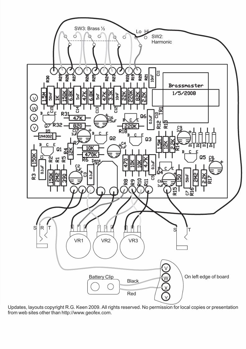
However... I have updated the PCB layout.
Updates, layouts copyright R.G. Keen 2009. All rights reserved. No permission for local copies or presentarom web sites other than http://www.geofex.com.

8/7/2019 BrassBlaster2
http://slidepdf.com/reader/full/brassblaster2 2/3
3
4
5
1
15
2
13
14
12 +9
+9+9
+8
+9
+9
+8
+8
+8
+9
R17
10K
4.7K
R9
R11470R
R7
470K
C6
1uF
C41uF
Q2 Q3
C1
C3
C5
C9
C8
C2
C14C13
C12
C15
C10
C11
0.1uF
0.1uF
0.1uF
0.1uF
R1
R4
390R150K2.2MR2
150KR3 12K
12K
10K
10K
10K
Q1
1uF
1uF
1uF
VR1
VR2
VR3
Q4 Q5
Q6
Q6
R5
R12
R13
R15
R14 R18
R19
R6
R10
R8
C7
1.5M
150R
2.2K
2.2K47nF
10nF
47nF
4.7nF 4.7nFT1
R21
R29
R31
R30
R22
R26
R27
R24
R23
R25
R28
R20
R16
220K
220K
82K
150K 1.5M
1K
22K
47K 47K 47K
2.2K
3.3K
6.8K 6.8K
In
Out
2M29 Vd c
1N4002C1625uF
C1710uF
R32820R
D5
D1
D2 D3
D4
A B C D E F G H I
K
J
LMNOPQRSTU
V
W
X
Y
V
W
X
Y
Updates, layouts copyright R.G. Keen 2009. All rights reserved. No permission for local copies or presentarom web sites other than http://www.geofex.com.
8/7/2019 BrassBlaster2
http://slidepdf.com/reader/full/brassblaster2 3/3
SW3: Brass ½
SW2:Harmonic
HiLo
S SR T T
VR1 VR2 VR3
V
V
W
W
X
X
Y
Y
Black
Red
Battery Clip On left edge of board
Updates, layouts copyright R.G. Keen 2009. All rights reserved. No permission for local copies or presentarom web sites other than http://www.geofex.com.