advances in the analysis of npp and other critical structures … · programa de pós-graduação...
TRANSCRIPT

Universidade Federal do Rio Grande do Sul Programa de Pós-Graduação em Engenharia Civil Laboratório de Dinâmica Estrutural e Confiabilidade (LDEC)
Advances in the analysis of NPP
and other critical structures
subjected to aircraft impact
Jorge D. Riera Universidade Federal do Rio Grande do Sul
Porto Alegre, RS, Brasil
International Nuclear Conference:
Bulgarian Nuclear Energy – Regional, National and International World Energy Safety
Varna, Bulgaria, June 5-7, 2013
(1) Federal University of Rio Grande do Sul, Porto Alegre, RS, Brazil
1. Introduction
The determination of the risk of failure of critical NPP structures
subjected to aircraft impact was initially performed by means of a
decoupled analysis, in which the forces induced by an incoming
projectile impacting against a rigid target, assessed in an inital step,
were applied on the target structure in a second, independent step, to
evaluate its response.
Various approaches were later proposed to account for the
influence on the interface forces - between projectile and target
structure - of motion of the latter. An extensive body of both
experimental and theoretical research was directed to the verification
of the predictions of the available models and the assessment of
model error.
1. Introduction
As the capacity of available hardware increased,
coupled analysis of both aircraft and structure became
feasible, which eliminated the need to assess the
influence of motion of the target structure on the
interface forces. This approach, illustrated by
examples in Section 3, is more expensive and cannot
be easily incorporated in codes or regulations.
1. Introduction
On the other hand, while predictions of the structural
response for impact loading that do not result in significant
structural damage may be expected to be characterized by
uncertainty levels usually admissible in dynamic analysis,
the same statement is not valid in cases of large damage or
partial failure. Recent round robin projects suggest that in
these cases prediction errors of the response may largely
exceed engineering tolerance. The uncertainty is attributed
to factors such as the inappropriate choice of material
model, which in reinforced or pre-stressed concrete
structures should account for fracture, size and rate effects.
Finally, recent research on these factors is briefly
reviewed.

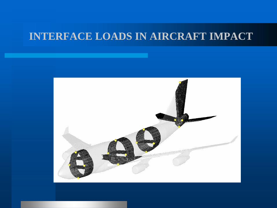
INTERFACE LOADS IN AIRCRAFT IMPACT
The US NRC (ex-AEC) requested in 1968 a safety
evaluation of the Three-Mile Island (Unit 1) NPP against
an accidental aircraft impact, on account of the plant
proximity to Harrisburg Airport. The potential effects of
fire were also assessed and adequate protective measures
taken, although no verification of impact-induced
vibrations of equipment was performed at the time (Gilbert
Assoc. Inc., 1968).

INTERFACE LOADS IN AIRCRAFT IMPACT
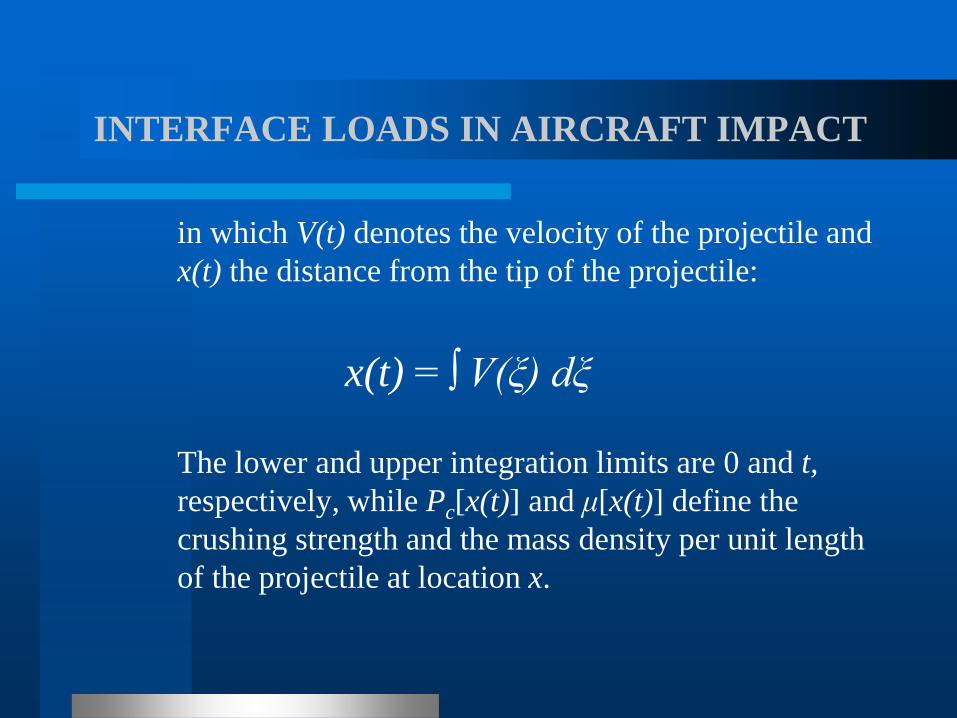
For purposes of structural analysis, the problem was
uncoupled. The time dependent reaction Fx (t) of a flat rigid
barrier against a normally impacting aircraft was evaluated
first, in order to be applied to the target structure in a
second, independent step (Riera, 1968). Assuming a rigid-
perfectly plastic behavior of the projectile (aircraft) and zero
residual velocity after impact, it was shown that:
Fx (t)= Pc [x(t)] + μ [x(t)] V2(t)
INTERFACE LOADS IN AIRCRAFT IMPACT
in which V(t) denotes the velocity of the projectile and
x(t) the distance from the tip of the projectile:
x(t) = ∫ V(ξ) dξ
The lower and upper integration limits are 0 and t,
respectively, while Pc[x(t)] and μ[x(t)] define the
crushing strength and the mass density per unit length
of the projectile at location x.
INTERFACE LOADS IN AIRCRAFT IMPACT
The approach is applicable to structures that do
not undergo large displacements as a consequence
of impact and was applied by Drittler and Grüner
(1976) to determine the forces induced by a
Phantom jet aircraft crashing at 215m/s on a rigid
target. A simplified load vs. time diagram based
on this analysis was subsequently adopted in
Germany as a standard requirement in NPP
structural design.
INTERFACE LOADS IN AIRCRAFT IMPACT
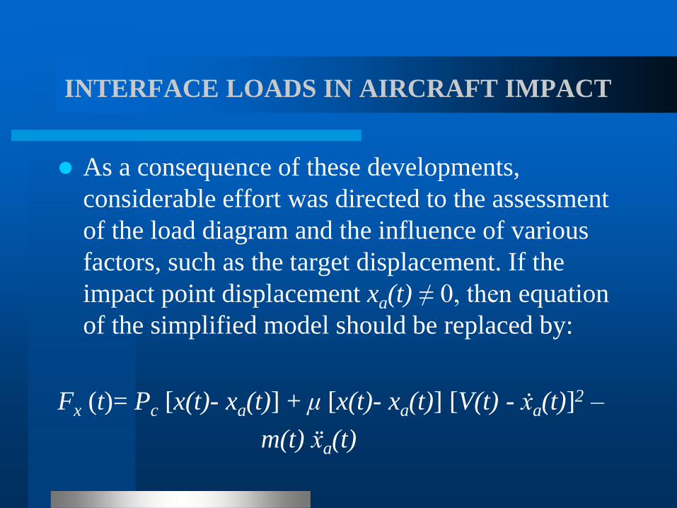
As a consequence of these developments,
considerable effort was directed to the assessment
of the load diagram and the influence of various
factors, such as the target displacement. If the
impact point displacement xa(t) ≠ 0, then equation
of the simplified model should be replaced by:
Fx (t)= Pc [x(t)- xa(t)] + μ [x(t)- xa(t)] [V(t) - ẋa(t)]2 –
m(t) ẍa(t)

INTERFACE LOADS IN AIRCRAFT IMPACT
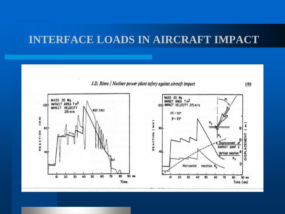
Dots denote derivatives with respect to time and
m(t) is the crushed mass of the aircraft at the impact
point. Riera (1980, 1982) examined the influence of
the impact angle in relation to the normal to the
surface and the effect of sliding along the surface
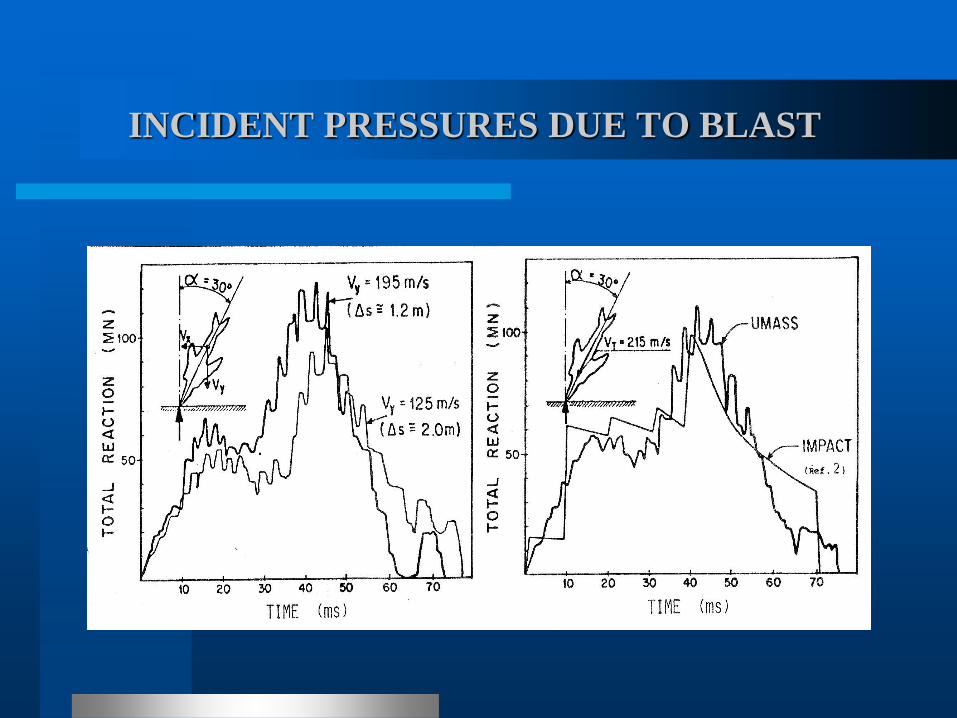
during the crash. Next figures show the reactions
induced by impact of a Phantom jet determined by
the simplified model and by Drittler and Grüner
(1976), as well as the reactions computed for impact
at a 30º angle with the normal.
INTERFACE LOADS IN AIRCRAFT IMPACT
INTERFACE LOADS IN AIRCRAFT IMPACT
In the 80’s, there was growing concern with the vibrations
induced on the reactor and other critical components by an
aircraft impact against the containment building (Riera,
1982). This would require the determination of floor
response spectra, similar to those introduced earlier in
seismic design. The displacements of the structure at the
impact location and induced local damage, which exert
marginal influence on the verification of the strength of the
target structure, may have an significant effect on induced
vibrations.
INCIDENT PRESSURES DUE TO BLAST

INTERFACE LOADS IN AIRCRAFT IMPACT
Experimental verification of the predictions of impact loading was deemed essential and led to a testing program conducted in Meppen, Germany, in which 6m long steel tubes were launched against instrumented reinforced concrete plates. A parallel series of experiments were conducted at the Winfrieth site in England, employing 1:10 reduced scale models of the projectiles used in Meppen. Next figure shows a detail of the Winfrieth projectile.
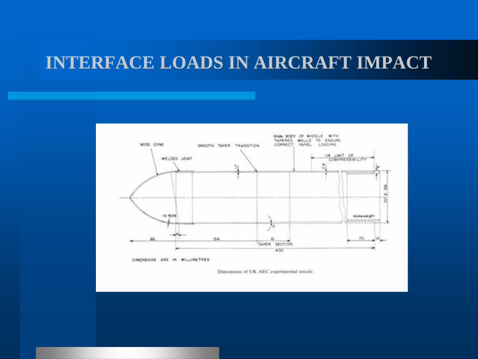
INTERFACE LOADS IN AIRCRAFT IMPACT
INTERFACE LOADS IN AIRCRAFT IMPACT
0
50
100
150
200
250
300
350
400
0,00 0,50 1,00 1,50 2,00 2,50 3,00 3,50
Time [ms]
F [
KN
]
test1
test 2
test 3
test 4
Mean
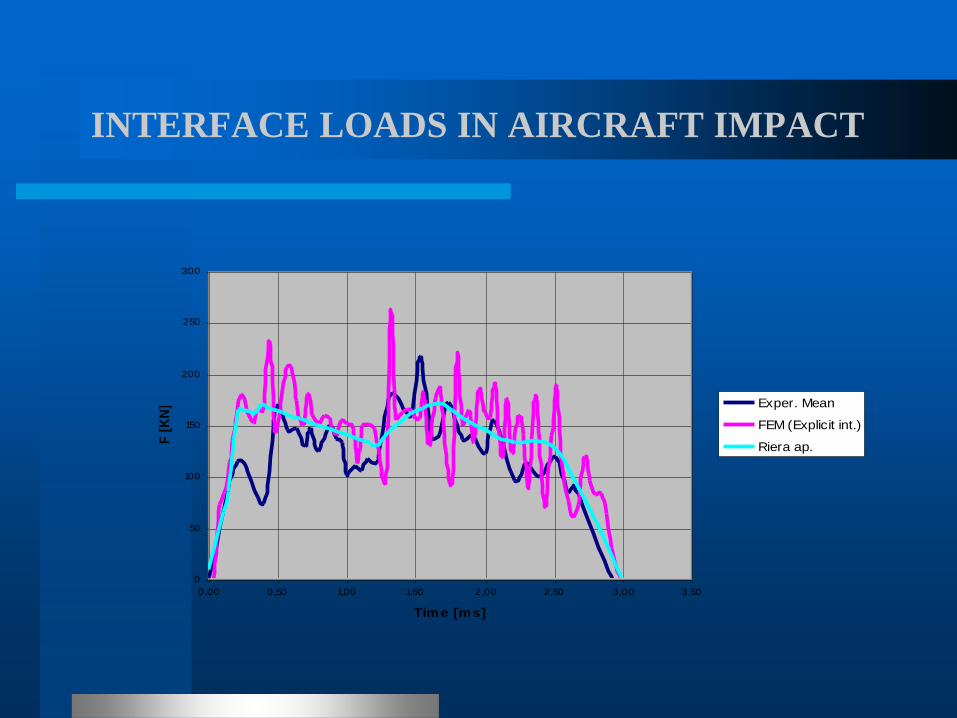
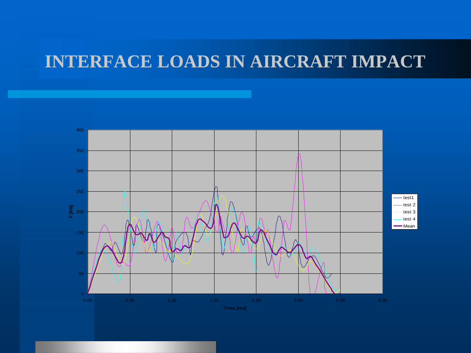
INTERFACE LOADS IN AIRCRAFT IMPACT
0
50
100
150
200
250
300
0,00 0,50 1,00 1,50 2,00 2,50 3,00 3,50
Tim e [ms]
F [
KN
] Exper. Mean
FEM (Explicit int.)
Riera ap.
INTERFACE LOADS IN AIRCRAFT IMPACT
A comprehensive summary of developments in this area until 1989, as reflected in SMiRT Transactions, was presented during SMiRT 10 and is partially reproduced in Table 2.1. As a consequence of these research efforts, the assumptions introduced in 1968 concerning the so-called soft behavior of both military and commercial aircraft, which for unyielding targets results in ideally plastic impact, were firmly consolidated and became the standard approach for analysis and design of NPPs (NEI 07-13, Revision 7, 2009).

INTERFACE LOADS IN AIRCRAFT IMPACT
The author is not aware of any attempt to statistically quantify model error in the assessment of loads induced by aircraft impact on NPP structures, i.e. the contribution of the model adopted by the designer to total uncertainty, but it should be emphasized that it is not large, being comparable to model error in any standard structural dynamics problem. In terms of the peak of the mean reaction vs. time function, it is suggested that the coefficient of variation of model predictions is of the order of 0.05.
INTERFACE LOADS IN AIRCRAFT IMPACT
In this conection, the experimental determination performed at SANDIA Laboratories of forces induced on a massive concrete block by a Phantom aircraft impacting at 215 m/s (von Riesemann et al, Muto et al, 1995) must be mentioned at this point. The carefully planned and conducted test, employing a full-scale aircraft at the design flying velocity, led the authors to conclude that “the analysis and evaluation gave an accurate impact force-time curve under the test conditions and confirmed that the existing Riera approach with slight modifications is a practical way of evaluating the impact force”.
INTERFACE LOADS IN AIRCRAFT IMPACT
It is thus quite clear that, in view of the Meppen, Winfrieth and SANDIA experiments, no major uncertainty remains in connection with the model to determine the interface reaction, although by precaution it is always advisable to accept that there is some inherent uncertainty in the procedure. The previously suggested 5% coefficient of variation to account for model uncertainty in this case appears to be a reasonable value.
INTERFACE LOADS IN AIRCRAFT IMPACT
To illustrate this point, let us examine next figure, reproduced from Muto et al (1995) which shows the distribution of the crushing strength Pc(x) of the Phantom admitted by Drittler and Grüner (1976) and by Zorn et al (1981) in their assessments of the load-time function, jointly with the distribution inferred by Muto et al (1995) from the measured reaction, which is also affected by large experimental and numerical errors. The uncertainty concerning the crushing load is not negligible, although it plays a small influence because the velocity term is predominant for the range of impact velocities of interest.

INTERFACE LOADS IN AIRCRAFT IMPACT
INTERFACE LOADS IN AIRCRAFT IMPACT
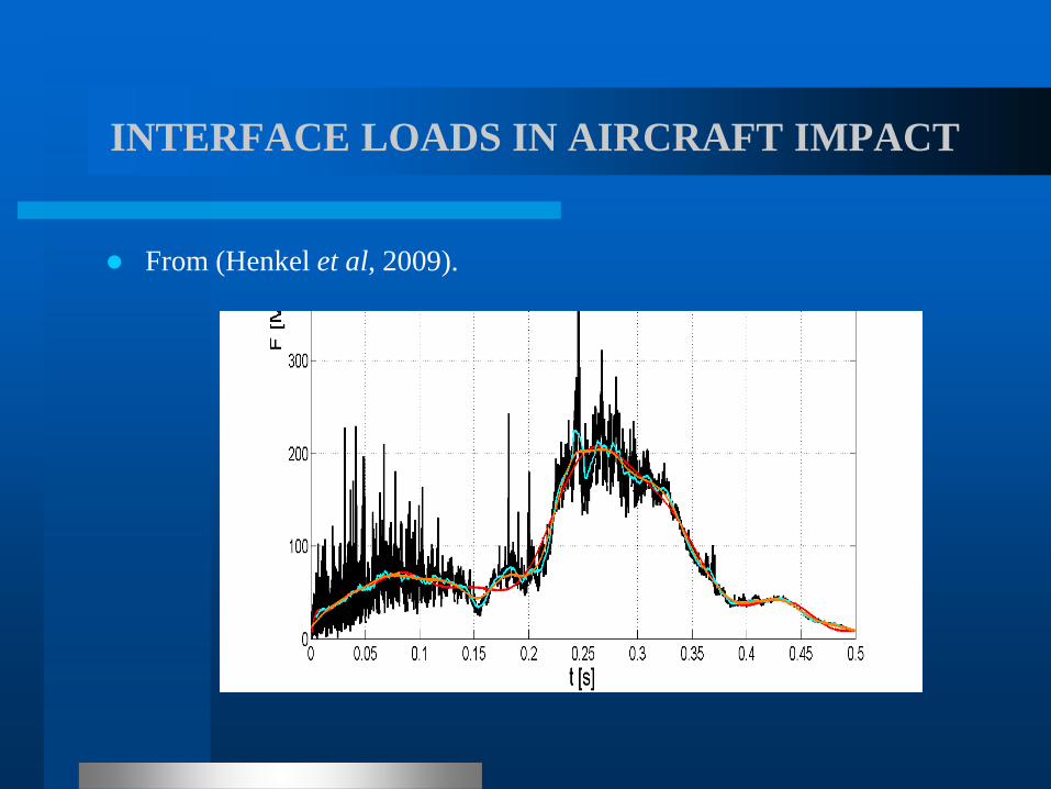
INTERFACE LOADS IN AIRCRAFT IMPACT
From (Henkel et al, 2009).
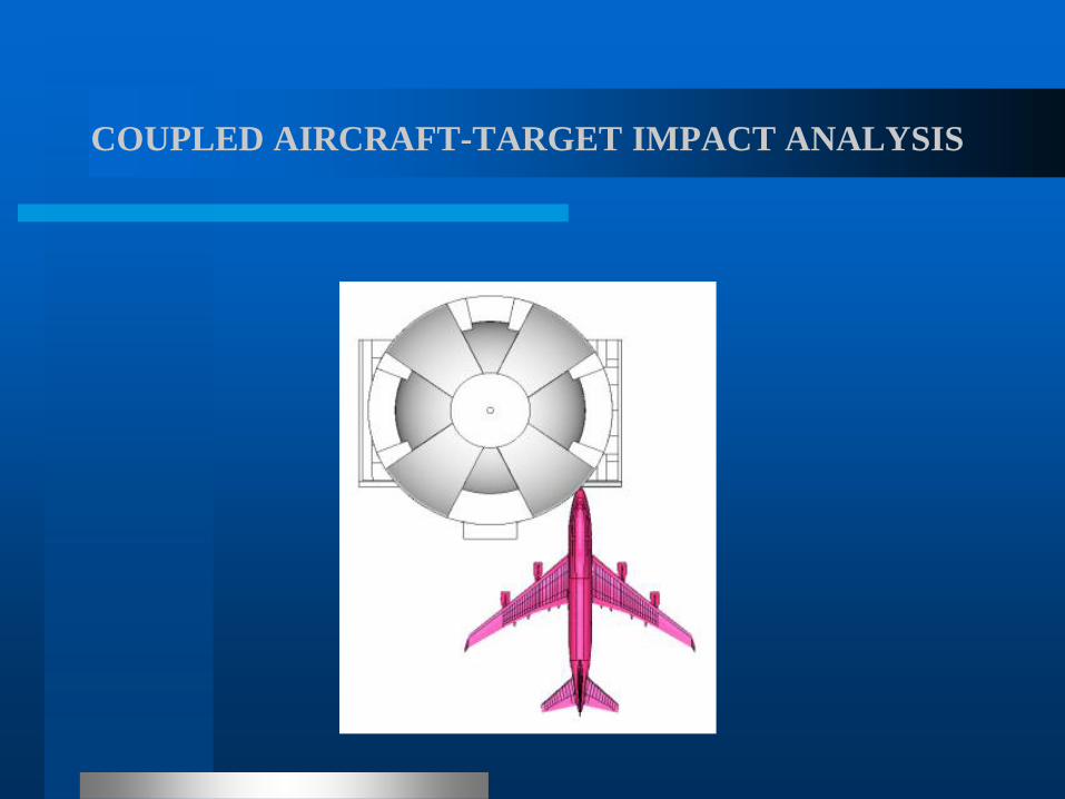
COUPLED AIRCRAFT-TARGET IMPACT ANALYSIS
The model of a Boeing B747 aircraft, briefly described
above, was coupled in ensuing studies with a complete
FEM model of a NPP containment building [Henkel et al
(2009) and Risk Engineering (2009)]. Such analysis
typically involves several millions DOF models, implying
high computing costs as well as great pre- and post-
processing design efforts. On the other hand, a global
analysis presents advantages, by freeing the analyst from
the need to make difficult decisions in the development of
the model to reduce its size without losing precision and/or
information.
COUPLED AIRCRAFT-TARGET IMPACT ANALYSIS
COUPLED AIRCRAFT-TARGET IMPACT ANALYSIS
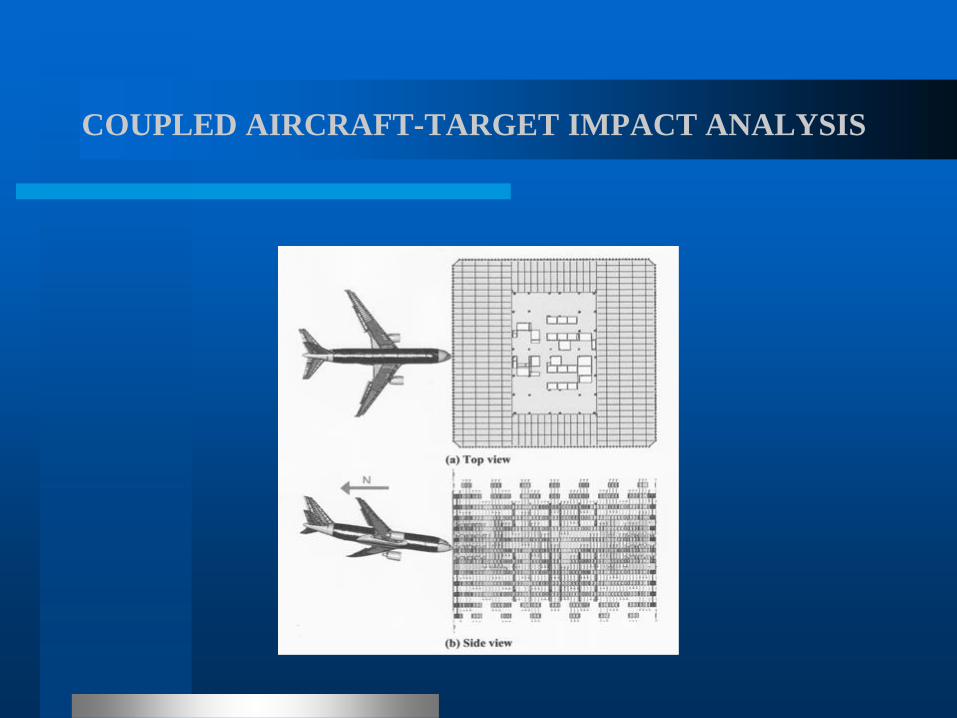
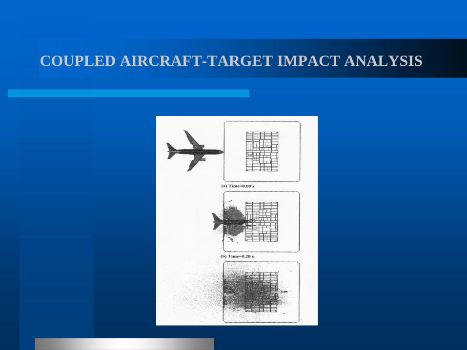
A large model, with 2.3 million nodes, was recently used by
Kirkpatrick et al (2009) to determine the nonlinear dynamic
response of the World Trade Center (WTC) Tower 1 to
aircraft impact. Top and side views of the coupled aircraft-
target model at the time of initial contact are shown first,
while next figure presents top views of the positions of nodal
points at the building elevation where impact took place, at
various times (0s, 0.2s and 0.5s) from the initiation of impact.
The analysis was performed using LS-Dyna Computer Code
on a cluster of twelve 2.8 GHz Intel Xeon Processors with a
run time of approximately two weeks.
COUPLED AIRCRAFT-TARGET IMPACT ANALYSIS
COUPLED AIRCRAFT-TARGET IMPACT ANALYSIS

COUPLED AIRCRAFT-TARGET IMPACT ANALYSIS
Various numerical techniques were tested, leading to
the adoption of SPH to model fuel in the global
impact analysis due to computational efficiency.
Comparisons of predicted and observed response, in
particular damage distribution, suggest a close
agreement, but since it was not a blind analysis, it is
difficult to extend this conclusion to typical design
situations. The issue will be addressed again later.

STRUCTURAL RESPONSE: THE DEM APPROACH
It is clear now that for predicting the response up to failure of
solids subjected to dynamic loads, in particular post-peak
response, methods based on Continuum Mechanics present
disadvantages in comparison with discrete models of the
solids under consideration.
This is a consequence of material fracture, which introduces
discontinuities in the displacement functions that are difficult
to handle in a continuum formulation and fostered the rapid
development of more efficient methods of analysis.
STRUCTURAL RESPONSE: THE DEM APPROACH
Among various such alternative methods, the so-
called truss-like Discrete Element Method (DEM)
proved quite useful. The approach was proposed by
Riera (1984) to determine the dynamic response of
plates and shells under impact loading when failure
occurs primarily by shear or tension, which is
generally the case in concrete structures.

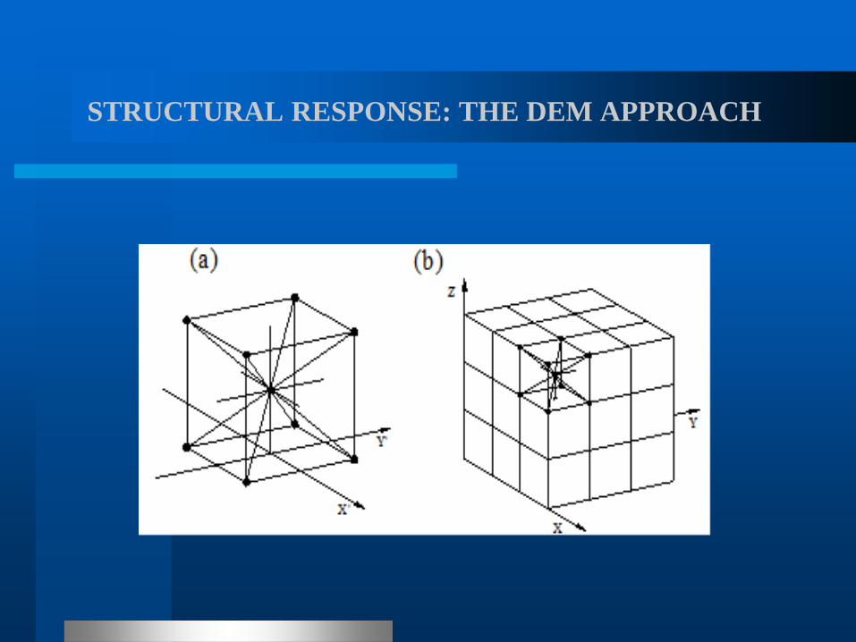
STRUCTURAL RESPONSE: THE DEM APPROACH
The Discrete Element Method (DEM) is based on the
representation of a solid by means of an arrangement of nodal
masses linked by elements able to carry only axial loads. The
discrete elements representation of an orthotropic continuum
was adopted to solve structural dynamics problems by means
of explicit direct numerical integration of the equations of
motion. Each node has three degrees of freedom,
corresponding to the nodal displacements in the three
orthogonal coordinate directions.
STRUCTURAL RESPONSE: THE DEM APPROACH
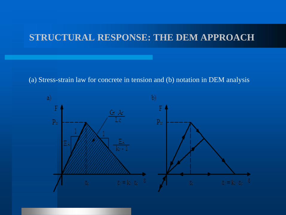
STRUCTURAL RESPONSE: THE DEM APPROACH
(a) Stress-strain law for concrete in tension and (b) notation in DEM analysis
STRUCTURAL RESPONSE: THE DEM APPROACH
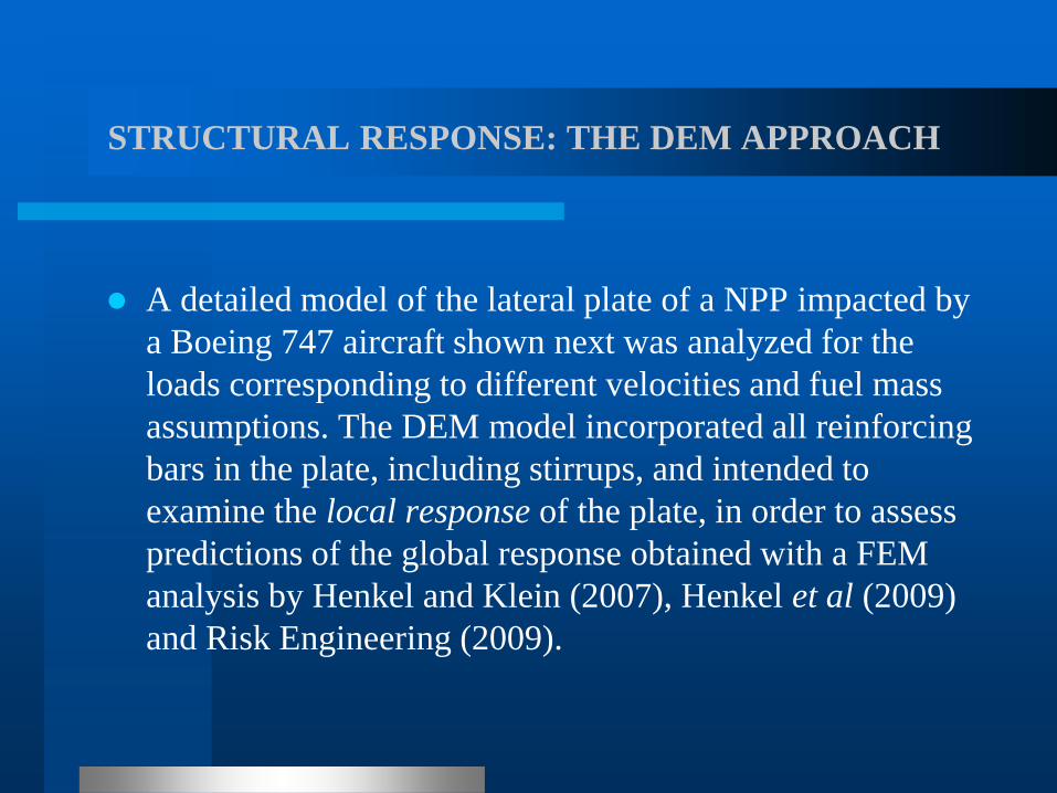
A detailed model of the lateral plate of a NPP impacted by
a Boeing 747 aircraft shown next was analyzed for the
loads corresponding to different velocities and fuel mass
assumptions. The DEM model incorporated all reinforcing
bars in the plate, including stirrups, and intended to
examine the local response of the plate, in order to assess
predictions of the global response obtained with a FEM
analysis by Henkel and Klein (2007), Henkel et al (2009)
and Risk Engineering (2009).
STRUCTURAL RESPONSE: THE DEM APPROACH
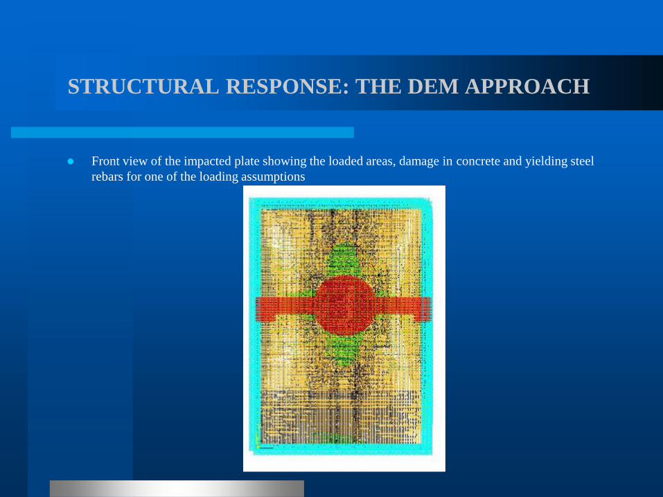
Front view of the impacted plate showing the loaded areas, damage in concrete and yielding steel
rebars for one of the loading assumptions
STRUCTURAL RESPONSE: THE DEM APPROACH
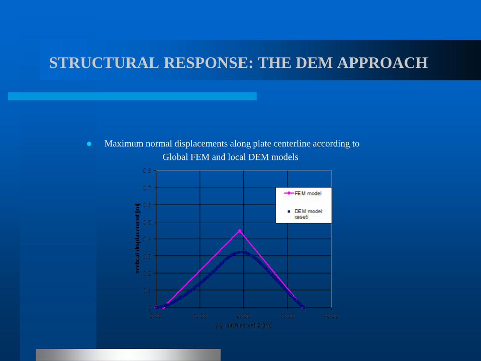
Maximum normal displacements along plate centerline according to
Global FEM and local DEM models
STRUCTURAL RESPONSE: THE DEM APPROACH
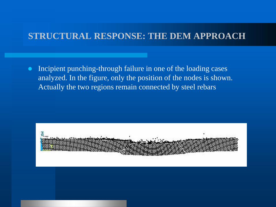
Incipient punching-through failure in one of the loading cases
analyzed. In the figure, only the position of the nodes is shown.
Actually the two regions remain connected by steel rebars
STRUCTURAL RESPONSE: THE DEM APPROACH
Under impact, blast and other short duration loadings, it
has long been acknowledged that the strength of
engineering materials tends to increase with the loading or
the strain rate. In DEM applications, the authors have
noticed that simulations conducted on samples of fragile,
inhomogeneous materials subjected to various loading
conditions, tend to fail under increasing loads when the
loading rate increases.
STRUCTURAL RESPONSE: THE DEM APPROACH
The issue raised a number of questions, such as the need to
explain the capacity of the DEM to predict, at least
approximately, the increase typically observed in load-
carrying capacity of structural systems subjected to impact
and blast loadings, the need to assess the correlation with
experimental results under different loading conditions
and, last but not least, to critically examine the
experimental evidence for very high strain rates available
in the technical literature.
STRUCTURAL RESPONSE: THE DEM APPROACH
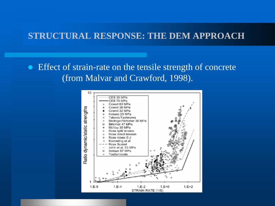
Effect of strain-rate on the tensile strength of concrete
(from Malvar and Crawford, 1998).

STRUCTURAL RESPONSE: THE DEM APPROACH
Envelopes of experimental observations of the dynamic/static strengths
ratio (η) for concrete in uniaxial tension (Malvar and Crawford , 1998
and Cotsovos and Pavlovic, 2008) in black lines, and in continuous
blue line DEM prediction (from Miguel et al., 2012).
STRUCTURAL RESPONSE: THE DEM APPROACH
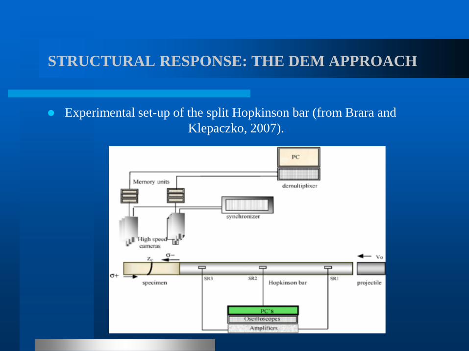
Experimental set-up of the split Hopkinson bar (from Brara and
Klepaczko, 2007).
STRUCTURAL RESPONSE: THE DEM APPROACH
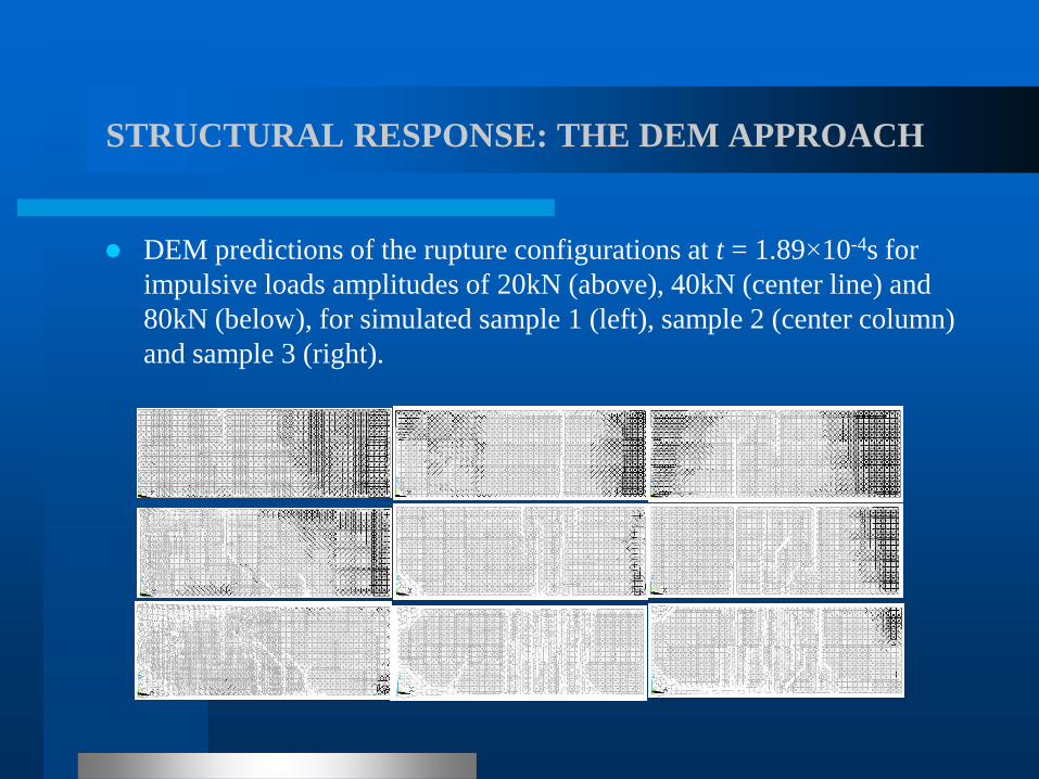
DEM predictions of the rupture configurations at t = 1.89×10⁻⁴s for
impulsive loads amplitudes of 20kN (above), 40kN (center line) and
80kN (below), for simulated sample 1 (left), sample 2 (center column)
and sample 3 (right).
STRUCTURAL RESPONSE: THE DEM APPROACH
A surprising prediction of simulation studies was the
detection of strain rate effects, that is, the computed
strength of structural elements was observed to increase as
the loading or strain rates increase, without any change in
the constitutive equations or material parameters. Studies
were then aimed at determining the response of cubic
samples subjected to controlled displacements, which
confirmed the capacity of the DEM to predict the
experimentally observed strength increase with the strain
rate. However, this conclusion is limited to strain rates
smaller than about 1/s.
STRUCTURAL RESPONSE: THE DEM APPROACH
Hence, modified split Hopkinson bar published test results
were simulated next, employing the DEM formulation,
which was able to reproduce the observed failure
configurations, but in contradiction with published results
in the technical literature, do not predict large tensile
strength increases (ratios η larger than about 5) or large
specific fracture energy increases with the strain rate.

FINAL REMARKS ON INHERENT UNCERTAINTIES
The Round Robin Project IRIS 2012 requested predictions
of the complete response of samples with specified
nominal properties of five structural systems (a) to (e). The
first three cases refer to static standard tests employed to
determine material properties to be used in the response
predictions of the ensuing impact problems (d) and (e).

FINAL REMARKS ON INHERENT UNCERTAINTIES
A total of 27 qualified participants submitted 135 complex
analyses, each of which demands careful consideration of
material models, numerical simulation, boundary
conditions, among other relevant issues, rendering the task
of conducting a critical review simply overwhelming.
Thus a final, global review has not yet been completed due
to various circumstances. Nevertheless, the IRIS 2012
Proceedings constitute an extremely valuable depository of
data on both Model and Phenomenological Uncertainties.

FINAL REMARKS ON INHERENT UNCERTAINTIES
The models employed by IRIS 2012 participants may be
classified in the following groups:
(1) Models based on a Continuum Mechanics approach to
the material behavior of solids, such as the Finite Element
Method (FEM) or Boundary Element Method (BEM)
formulations. The approach constitutes the standard
method of analysis of linear elastic structural systems.

FINAL REMARKS ON INHERENT UNCERTAINTIES
(2) Models based on the representation of structural
systems by a collection of discrete elements or bodies,
which cannot be subdivided, linked by massless
elements, (or simply inter-element forces), which
when rupture occurs give rise to fissures or cracks,
that is, to discontinuities in the system. These models
are herein grouped within the so-called Discrete
Element Methods (DEM).

FINAL REMARKS ON INHERENT UNCERTAINTIES
(3) An approach derived from the numerical analysis of
large groups of particles, initially applied to the study of
the formation and evolution of proto-stars and of fluid flow
and now extensively used in the determination of the
response of solids that experience plastic flow, fracture and
fragmentation, known as Smoothed Particle
Hydrodynamics (SPH). The approach shares some
common features with DEM, except that in the former
inter-particle forces can exist between any pair of particles
in the system, while in the latter they are typically
restricted to initially neighbor particles.
FINAL REMARKS ON INHERENT UNCERTAINTIES
It was suggested before that the mean load-time function
for aircraft impact against target structures that suffer
minor damage during the crash may be determined with
small uncertainty, reflected in the proposed coefficient of
variation of the peak load CV= 0.05.
A preliminary evaluation of IRIS 2012 results led to CV of
the parameters defining peak structural response not
smaller than 25%, fact that should be taken into account in
the assessment of numerical response predictions.

FINAL REMARKS ON INHERENT UNCERTAINTIES
Finally, note that the uncertainty inherent in
methods of analysis in group (a) (FEM approach)
and (b) (DEM approach), as described above, may
be expected to be smaller than the uncertainty
associated to methods (c) (SHP approach), which
are still in the stage of experimentation and
consolidation.
CONCLUSIONS
A brief overview of analysis and design criteria of
structures subjected to aircraft impact was presented,
focusing attention on factors considered of relevance for
NPP design. One of these factors is related to model
uncertainty, i.e. to the degree of belief of the designer in
the numerical or analytical model employed to determine
the structural response. Note that uncertainty grows as we
approach the limits of past experience, region in which the
analyst and design engineer find themselves when
assessing the effects of aircraft impact.

CONCLUSIONS
Finally, I wish to express my sincere thanks to
BULATOM organizers for the opportunity
provided by their invitation to exchange
knowledge, experiences and ideas to make
Nuclear Power safer and more reliable.