(*$6021,= ,167,7872683(5,25'(&,Ç1&,$6'$6$Ò'( - rcaap · figure 16....
TRANSCRIPT

INSTITUTO SUPERIOR DE CIÊNCIAS DA SAÚDE EGAS MONIZ
MESTRADO INTEGRADO EM CIÊNCIAS FARMACÊUTICAS
DESIGN/OPTIMIZATION/INTRODUCTION OF DISPOSABLES FOR BIOTECH DRUG PRODUCT PROCESSES
Trabalho submetido por Joana Demmich Barbosa Agostinho
para a obtenção do grau de Mestre em Ciências Farmacêuticas
Novembro de 2014

INSTITUTO SUPERIOR DE CIÊNCIAS DA SAÚDE EGAS MONIZ
MESTRADO INTEGRADO EM CIÊNCIAS FARMACÊUTICAS
DESIGN/OPTIMIZATION/INTRODUCTION OF DISPOSABLES FOR BIOTECH DRUG PRODUCT PROCESSES
Trabalho submetido por Joana Demmich Barbosa Agostinho
para a obtenção do grau de Mestre em Ciências Farmacêuticas
Trabalho orientado por Doutor André Mang
Prof. Doutora Carla Ascenso
Novembro de 2014


3
To my parents, who have always guided me and been by my side.
4
Acknowledgments
I thank my university Instituto Superior de Ciências da Saúde Egas Moniz and all its
teachers and staff for all the knowledge and values taught during these last five years.
I also want to thank my teacher Prof. Doutora Carla Ascenso for all the support, for
believing in me and for giving me the opportunity to enrich my knowledge.
I also thank my chief and mentor Doctor André Mang and all his team for the opportunity
given to enrich my knowledge, for all the help and support and for all the share of
knowledge.
I am thankful to all my dear friends and university colleagues for these wonderful five
years and for all the good moments, but especially to Carolina Azevedo and Margarida
Rocha for their support, advices, help and true friendship.
To my best friend, Sara Jordão, whom I am also thankful for all the support in good and
bad moments, for believing in me, for all the advice, for her true friendship and for always
being by my side.
I also want to thank Nuno Lourisela for all his patience, for supporting me in good and
bad moments, for all his help, for believing in me, for always being by my side and for
his love.
Finally, I am thankful to the most important persons in my life, my parents and my whole
family, who during my life have guided me, supported me, helped me and believed in me
and for all the given strength and tools needed to overcome the daily barriers.

Abstract
5
Abstract
The Quality-Time-Cost Iron triangle is in the middle of a pharmaceutical commercial
production process. However, nowadays pharmaceutical companies try to optimize the
security level of sterility assurance, available capacity and costs, looking for innovative
technologies in order to improve their processes.
Within this master thesis, the possibility to transfer active pharmaceutical ingredient
solutions with a peristaltic pump and with overpressure in combination with a combined
thawing and transfer disposable tube was tested. Moreover, the transfer speeds of three
combined thawing and transfer disposable tubes in combination with the two transfer
methods were measured in order to decide which combined disposable tube and which
method is more suitable for the transfer of active pharmaceutical ingredient solutions and
therefore, see if it is advantageous to replace the current single thawing and single transfer
disposable tubes, taking also into account other additional factors.
It is possible to transfer active pharmaceutical ingredient with a peristaltic pump and
overpressure. However, the use of an optimized combined thawing and transfer
disposable tube in combination with the overpressure transfer method would be an
innovative process and would bring quality and efficiency to a pharmaceutical sterile drug
product manufacturing process.
Key words: disposable technologies combined thawing and transfer disposable tube,
peristaltic pump, overpressure

Design/Optimization/Introduction of Disposables for Biotech Drug Product Processes
6
Resumo
O triângulo de ferro qualidade-tempo-custo está no seio do processo farmacêutico de
produção comercial. No entanto, nos nossos dias, as empresas farmacêuticas tentam
otimizar o nível de segurança de garantia da esterilização, a capacidade disponível e os
custos, procurando melhorar os seus processos produtivos por recurso a tecnologias
inovadoras.
No âmbito desta tese, foi testada a possibilidade de transferência de soluções de
ingredientes farmacêuticos ativos, por recurso a dois métodos de transferência de fluidos,
bomba peristáltica e sobrepressão, em combinação com um tubo descartável de
descongelamento e transferência. Além disso, foram medidas as velocidades de
transferência através dos dois métodos utilizando três alternativas de tubos descartáveis
combinados de descongelamento e transferência, de forma a decidir qual o método e o
tubo descartável combinado mais adequados para a transferência de soluções de
ingredientes farmacêuticos ativos e, por conseguinte, verificar se é vantajoso proceder à
substituição dos atuais tubos descartáveis, um de descongelamento e outro de
transferência, tendo igualmente em consideração outros fatores adicionais necessários à
tomada de decisão.
É possível transferir ingredientes farmacêuticos ativos através de bomba peristáltica e
através de sobrepressão. Contudo, a utilização otimizada de um tubo descartável
combinado de descongelamento e transferência, empregando o método de transferência
de sobrepressão, seria um processo inovador que traria qualidade e eficiência ao processo
de produção de produtos farmacêuticos estéreis.
Palavras-chave: tecnologias descartáveis, tubos descartáveis combinados de
descongelamento e transferência, bomba peristáltica, sobrepressão
Table of Contents
7
Table of Contents
Acknowledgments ............................................................................................................ 4
Abstract ............................................................................................................................. 5
Resumo ............................................................................................................................. 6
Figure index ...................................................................................................................... 9
Table index ..................................................................................................................... 12
Abbreviations ................................................................................................................. 13
Glossary .......................................................................................................................... 14
1. Introduction ................................................................................................................. 17
1.1. Disposable technologies ...................................................................................... 17
1.1.1. Examples of disposable technologies ............................................................ 19
1.1.2. Disadvantages................................................................................................ 19
1.1.3. Advantages .................................................................................................... 20
1.1.4. Qualification and Validation ......................................................................... 22
1.1.5. Environmental impact ................................................................................... 23
1.2. Highly potent drugs ............................................................................................. 26
1.2.1. Facility design ............................................................................................... 28
1.3. Cryo-vessel .......................................................................................................... 29
1.4. Tubings and Connectors ...................................................................................... 30
1.4.1. Tubings .......................................................................................................... 30
1.4.2. Connectors ..................................................................................................... 34
1.5. Fluid transfer ........................................................................................................ 37
1.5.1. Pump systems ................................................................................................ 37
1.5.2. Pressurizing ................................................................................................... 38
1.6. Influence of Pump systems and Pressurizing in protein solutions ....................... 39
2. Target .......................................................................................................................... 41

Design/Optimization/Introduction of Disposables for Biotech Drug Product Processes
8
3. Types of Cryo-vessels ................................................................................................. 42
3.1. US Cryo-vessel Type ........................................................................................... 42
3.2. Basel and Penzberger Cryo-vessel Types ............................................................ 44
4. Today’s Cryo-vessel process cycle (API), Roche Mannheim .................................... 47
5. Today’s API thawing and transfer process ................................................................. 48
6. Materials and Methods ............................................................................................... 53
6.1. Experiment ........................................................................................................... 56
6.1.1. Tube A. .......................................................................................................... 56
6.1.2. Tube B. .......................................................................................................... 59
6.1.3. Tube C. .......................................................................................................... 62
7. Results ......................................................................................................................... 66
8. Discussion ................................................................................................................... 76
8.1. Advantages of a combined thawing and transfer tube ......................................... 77
8.2. Disadvantages of a combined thawing and transfer tube..................................... 78
8.3. Selection of an adequate combined thawing and transfer disposable tube .......... 79
8.4. Recommendation of a transfer method ................................................................ 80
8.5. Recommendation of a combined thawing and transfer disposable tube .............. 81
8.6. Future research ..................................................................................................... 82
9. Conclusion .................................................................................................................. 83
10. References ................................................................................................................. 84

Figure index
9
Figure index
Figure 1. The Iron Triangle.. .......................................................................................... 17
Figure 2. Decision tree for management of solid waste ................................................. 26
Figure 3. Triclamp disposable (a) and a stainless steel clamp (b) .................................. 35
Figure 4. Quick-connectors: MPC® Series from Colder Company ................................ 35
Figure 5. Steam-Thru System® from Colder Company .................................................. 35
Figure 6. Lynx ST® from Millipore Company ............................................................... 35
Figure 7. Kleenpak KPC® by Pall .................................................................................. 36
Figure 8. Lynx S2S® by Millipore .................................................................................. 36
Figure 9. Opta SFT-1® by Sartorius Stedim Biotech ..................................................... 36
Figure 10. ReadyMate DAC® by GE ............................................................................. 36
Figure 11. Pure-Fit SC® by Saint-Gobain ...................................................................... 36
Figure 12. Classification of pumps ................................................................................. 37
Figure 13. US Cryo-vessel type: Filling, Thawing and Transfer processes ................... 42
Figure 14. US Cryo-vessel type of (a) 120 L and (b) 300 L, with upper and bottom
valves highlighted. ....................................................................................... 43
Figure 15. Basel and Penzberger Cryo-vessel: Filling, Thawing and Transfer
processes ...................................................................................................... 44
Figure 16. Penzberger Cryo-vessel type of 300 L (left) and close-up showing of
the upper valve (a) and of the dip tube (b)................................................... 45
Figure 17. Basel Cryo-vessel type of 300 L (left) and close-up showing of the upper
valve (a) and of the dip tube (b)................................................................... 45
Figure 18. Today’s Cryo-vessel process cycle in Roche Diagnostics GmbH,
Mannheim .................................................................................................... 47
Figure 19. Today’s thawing tube (a) attached with a Nova Septum® and a syringe for
sampling (b) ................................................................................................. 48
Figure 20. Upper valve of US Cryo-vessel (a) and connection of the thawing disposable
tube with the upper valve before the thawing process (b) ........................... 48
Figure 21. Bottom valve of US Cryo-vessel (a) and connection of the thawing
disposable tube with the bottom valve before the thawing process (b) ....... 49
Figure 22. The silicon oil cycle. (a) Entry of silicon oil in the cryo-vessel; (b)
Circulation of silicon oil in the double coat and in the inner tube snake
in the cryo-vessel; (c) Exit of silicon oil out of the cryo-vessel .................. 50
Design/Optimization/Introduction of Disposables for Biotech Drug Product Processes
10
Figure 23. Peristaltic pump for product circulation and the today´s thawing
disposable tube in the peristaltic pump for product circulation ................... 50
Figure 24. Operators lying on the floor to connect the transfer tube before
implementation of the adapter ..................................................................... 51
Figure 25. Adapter used for the today’s connection of the transfer tube with the US
Cryo-vessel .................................................................................................. 51
Figure 26. Operators doing the connection of the transfer tube after implementation
of the adapter ............................................................................................... 51
Figure 27. Today’s transfer disposable tube ................................................................... 52
Figure 28. Peristaltic pump (up) and manometer and overpressure tube (right) used
in the experiment ......................................................................................... 54
Figure 29. US Cryo-vessel (300 L) used in the experiment ........................................... 55
Figure 30. Filling the US Cryo-vessel with WFI ........................................................... 55
Figure 31. First disposable tube that was tested - Tube A .............................................. 56
Figure 32. US Cryo-vessel with Tube A in class D room .............................................. 57
Figure 33. Part C of tube A with Lynx S2S® connector and with a tube connection
piece (a) and Part C of Tube A after removing the Lynx S2S® connector
and with a tube connection piece (b) ........................................................... 57
Figure 34. Part C of Tube A passing through the peristaltic pump ................................ 58
Figure 35. Manometer (a), overpressure tube (blue tube) (b) and overpressure tube
connected to the US Cryo-vessel in class C-room (c) ................................. 58
Figure 36. Experiment design of Tube A (a) with peristaltic pump and (b) with
overpressure ................................................................................................. 59
Figure 37. Second disposable tube that was tested - Tube B ......................................... 59
Figure 38. US Cryo-vessel with Tube B in class D room .............................................. 60
Figure 39. Part E of Tube B passing through the peristaltic pump ................................ 60
Figure 40. Manometer (a) and overpressure tube (blue tube) (b) and overpressure
tube connected to the US Cryo-vessel in class C-room (c) ......................... 61
Figure 41. Experiment design of Tube B (a) with peristaltic pump and (b) with
overpressure ................................................................................................. 61
Figure 42. Third disposable tube that was tested - Tube C.. .......................................... 62
Figure 43. US Cryo-vessel with Tube C in class D room (a) and US Cryo-vessel
with Tube C connected to the y-connector in class D room (b) .................. 63

Figure index
11
Figure 44. Transfer concept for ADCs: connection of Tube C with y-connector and
connection of y-connector with the compounding tank .............................. 63
Figure 45. Part D of y connector (connected to Tube C) passing through the
peristaltic pump ........................................................................................... 64
Figure 46. Manometer (a), overpressure tube (blue tube) (b) and overpressure tube
connected to the Cryo-vessel in class C-room (c) ....................................... 64
Figure 47. Experiment design of Tube C with (a) peristaltic pump and (b)
overpressure ................................................................................................. 65
Figure 48. Transfer speed of the tubes with peristaltic pump ........................................ 67
Figure 49. Transfer speed of the tubes with overpressure .............................................. 68
Figure 50. Transfer speed of the tubes with peristaltic pump and overpressure ............ 68
Figure 51. Overview of some statistical analysis.. ......................................................... 69
Figure 52. Descriptive Statistics: Transferred amount/time with peristaltic pump and
transferred amount /time with overpressure ................................................ 70
Figure 53. Transferred amount/time of the tubes with peristaltic pump and
overpressure ................................................................................................. 71
Figure 54. Probability plot of the transferred amount/time with peristaltic pump
and overpressure .......................................................................................... 72
Figure 55. Interval plot for the transferred amount/time of the tubes with
peristaltic pump ........................................................................................... 73
Figure 56. Interval plot for the transferred amount/time of the tubes with
overpressure ................................................................................................. 73
Figure 57. One Way ANOVA table output for the transferred amount/time using
peristaltic pump ........................................................................................... 74
Figure 58. One Way ANOVA table output for the transferred amount/time using
overpressure ................................................................................................. 75
Figure 59. Cryo-vessel process cycle in Roche Diagnostics GmbH, Mannheim with
the application of a combined thawing and transfer disposable tube .......... 78
Figure 60. Steps that can be followed to evaluate if a disposable technology is
feasible from the business point of view in GMP-environment .................. 79

Design/Optimization/Introduction of Disposables for Biotech Drug Product Processes
12
Table index
Table 1. Common types of disposable technologies used in the biopharmaceutical
industry .......................................................................................................... 19
Table 2. Recycling advantages and constraints............................................................ 24
Table 3. Incineration advantages and constraints ........................................................ 25
Table 4. Landfill advantages and constraints ............................................................... 25
Table 5. High potency API evaluation and categorization .......................................... 27
Table 6. Example of plastic used for tubing (Silicone) ................................................ 31
Table 7. Example of plastics used for tubing (Thermoplastic elastomer).................... 32
Table 8. Example of plastic used for tubing (Copolymer) ........................................... 32
Table 9. Examples of plastics used for tubing (Fluoropolymers) ................................ 32
Table 10. Different types of connectors ......................................................................... 34
Table 11. Today´s Tube features .................................................................................... 49
Table 12. Features of the today´s transfer tube material ................................................ 49
Table 13. Combined thawing and transfer Tubes A, B and C features. ......................... 53
Table 14. Features of the tube materials used in the experiment ................................... 54
Table 15. Transfer speeds of Today´s Tube and Tube A, B and C ................................ 66
Table 16. Transferred amount/time of Today´s tube, Tube A, B and C ........................ 69
Table 17. Correspondence of the tubes for the statistical methods ................................ 70
Table 18. Advantages and disadvantages of the tested tubes......................................... 81
Abbreviations
13
Abbreviations
ADC - Antibody drug conjugate
ANOVA - Analysis of variance API - Active Pharmaceutical Ingredient
ASTM - American Society for Testing and Materials
Cfu – Colony forming units
cGMP – Current Good Manufacturing Practices
CI – Confidence interval
CIP – Clean- in- place
FDA – Food and Drug Administration
HPAPI – Highly potent active pharmaceutical ingredients
ID – Inner diameter
ISO – International Organization for Standardization
Kg – Kilograms
kGy - Kilogray
LAL - Limulus amebocyte lysate
Min - Minutes
OD – Outer diameter
OEB – Occupational exposure bands
OEL – Occupational exposure limits
QC – Quality Control
SIP – Sterilization- in- place
SOP – Standard operating procedures
StDev – Standard deviation
USP – United States Pharmacopeia
WFI – Water for injection
Design/Optimization/Introduction of Disposables for Biotech Drug Product Processes
14
Glossary
Active Pharmaceutical Ingredient - any substance or combination of substances used
in a finished pharmaceutical product, intended to furnish pharmacological activity or to
otherwise have direct effect in the diagnosis, cure, mitigation, treatment or prevention of
disease, or to have direct effect in restoring, correcting or modifying physiological
functions in human beings.
Aseptic - free of pathogenic microorganisms.
Batch - a quantity of any drug produced during a given cycle of manufacture.
Basic clean rooms – clean rooms that have control of airflow, air filtration, air velocity,
air changes, air pressure, airborne particulates, temperature, humidity and
microorganisms.
Bioburden - population of viable microorganisms on or in raw materials, products, and
labeling/packaging materials determined before sterilization.
Clean in place - cleaning of equipment in its assembled condition and at its location. This
cleaning may be an automatic process or manual. Whatever the method, it must comply
with the stringent hygiene regulations of the pharmaceutical industries.
Clean room area - an area (or room or zone) with defined environmental control of
particulate and microbial contamination, constructed and used in such a way as to reduce
the introduction, generation and retention of contaminants within the area.
Containment - a process or device to contain product, dust or contaminants in one zone,
preventing it from escaping to another zone.
Contamination - The undesired introduction of impurities of a chemical or
microbiological nature, or of foreign matter, into or on to a starting material, intermediate
or pharmaceutical product during handling, production, sampling, packaging or
repackaging, storage or transportation.
Class C – a clean area for carrying out less critical stages in the manufacture of sterile
products. In this clean area personal must take hair cover, beard cover, face mask, a
general protective suit, gathered at the wrists and with high neck, shoe covers and gloves.
This area has a maximum permitted number of particles per m3 at rest and in operation
and has recommended limits for microbial contamination. The maximum permitted

Glossary
15
number of particles per m3 equal to or greater than 0,5 µm is at rest 352000 and is in
operation 3520000. The maximum permitted number of particles per m3 equal to or
greater than 5 µm is at rest 2900 and is in operation 29000. The recommended limits for
microbial contamination in contact plates (Ø 55mm) are 25 cfu/plate.
Cross contamination - contamination of a starting material, intermediate product or
finished product with another starting material or product during production or due to
microorganisms.
Current Good Manufacturing Practices – is the aspect of quality assurance that ensures
that medicinal products are consistently produced and controlled to the quality standards
appropriate to their intended use and as required by the product specification.
Class D - a clean area for carrying out less critical stages in the manufacture of sterile
products. In this clean area personal must take hair cover, beard cover, a general
protective suit and shoe covers. This area has a maximum permitted number of particles
per m3 at rest and in operation and has recommended limits for microbial contamination.
The maximum permitted number of particles per m3 equal to or greater than 0,5 µm is at
rest 3520000 and is not defined in operation. The maximum permitted number of particles
per m3 equal to or greater than 5 µm is at rest 29000 and is not defined in operation. The
recommended limits for microbial contamination in contact plates (Ø 55mm) are 50
cfu/plate.
Endotoxin - lipopolysaccharide contained within the outer membrane of Gram-negative
bacteria that may lead to pyrogenic reactions and other biological activities in humans.
Gamma irradiation – the operation of exposing a material to gamma rays in order to
sterilize.
Gray space – non-defined clean room area.
LAL test - used for the detection and quantification of bacterial endotoxins.
Process qualification - confirming that the manufacturing process as designed is capable
of reproducible commercial manufacturing.
Process validation - documented evidence which provides a high degree of assurance
that a specific process will consistently result in a product that meets its predetermined
specifications and quality characteristics. Process validation is a requirement of current

Design/Optimization/Introduction of Disposables for Biotech Drug Product Processes
16
Good Manufacturing Practices. Process validation involves a series of activities taking
place over the lifecycle of the product and process.
Qualification - action of proving and documenting that equipment or ancillary systems are
properly installed, work correctly, and actually lead to the expected results. Qualification is
part of validation, but the individual qualification steps alone do not constitute process
validation.
Sanitization - process of decontamination that reduces viable microorganisms to a
defined acceptance level.
Shelf life - The period of time during which a pharmaceutical product, if stored correctly,
is expected to comply with the specification as determined by stability studies on a
number of batches of the product. The shelf-life is used to establish the expiry date of
each batch.
Spalling – is the removal of small particulate matter from the inner wall of flexible tubing
when subjected to repeated deformation and flexing.
Standard operating procedures – an authorized, written procedure giving instructions
for performing operations not necessarily specific to a given product but of a more general
nature (e.g. equipment operation, maintenance and cleaning, validation, cleaning of
premises and environmental control, sampling and inspection).
Sterile – complete absence of microorganisms.
Sterilization - complete destruction or removal of all microorganisms including spore-
forming and non-spore-forming bacteria, viruses, fungi, and protozoa.
Sterilization in place – sterilization of equipment in its assembled condition and at its
location.
Validation - action of proving and documenting that any process, procedure or method
actually and consistently leads to the expected results. It includes the qualification of
systems and equipment. In general, an entire process is validated.

Introduction
17
1. Introduction
1.1. Disposable technologies
It has been about a decade since disposable products were introduced to the
biomanufacturing industry. While disposables have been examined for years in less
regulated environments, disposable manufacturers had to demonstrate their benefits and
qualities to convince biomanufacturers to try them (Mintz, C. 2009; Whitford, W. G.,
2010).
Pharmaceutical drug products should be produced with efficiency (reduced costs and less
production time) and with high quality according to current Good Manufacturing
Practices (cGMP) as shown in the iron triangle (see figure 1) (Valle, C., 2009; Sandle, T.,
& Saghee, M. R., 2011). Quality-Time-Cost is in the middle of the development process.
At each verification point, choices have to be made, based on Quality-Time-Cost. There
must be a balance between the three pillars of the triangle. For example too little time
could lead to poor quality, which can prove very expensive later on. Therefore, ways have
to be found to improve quality and still cut on time and costs (Legrand, B., 2004).
However, the presence of microbiological contamination can affect the quality and the
efficiency leading to batch rejection. Therefore, an emphasis on risk reduction should be
an essential component of sterile product manufacturing. A focus on high quality
operating clean rooms, trained staff, the use of sterilized clean room items and recent
technologies are examples of what can be done to support this goal (Sandle, T., & Saghee,
M. R., 2011).
The development from basic clean rooms to novel clean room technologies over the last
years has resulted in a reduction on the risk of product contamination and in a
Figure 1. The Iron Triangle. Adapted from Atkinson, R. (1999).

Design/Optimization/Introduction of Disposables for Biotech Drug Product Processes
18
simplification of the process operation. These novel technologies include the following:
barrier isolated systems and RABS (restricted access barrier systems) to protect the
aseptic filling; methods to protect the product from personnel contamination such as
particle reducing air showers; sanitization and sterilization methods to decontaminate
clean rooms and sterile disposable technologies. The use of disposable technologies
allowed pharmaceutical companies to substitute equipment that needs to be sterilised by
disposable items (Sandle, T., & Saghee, M. R., 2011).
Nowadays pharmaceutical companies are under pressure to increase productivity and
profitability. In addition, there is a concern about costs, available capacity and sterility
assurance, forcing them to look for available technologies in order to optimize their
processes (Sinclair, A., & Monge, M., 2002; Aranha, H., 2004). As a consequence, some
pharmaceutical companies have incorporated disposables technologies in the
biopharmaceutical and biotechnology sectors (Sandle, T., & Saghee, M. R., 2011).
Single-use technologies, which are generally sterile, plastic items, have been adopted in
order to replace traditional pharmaceutical processing items, like stainless steel that
require cleaning, recycling and in-house sterilization (Sandle, T., & Saghee, M. R., 2011).
Disposables are available in different formats and can be rigid or flexible. They are
usually manufactured from plastic polymers approved by the Food and Drug
Administration (FDA) (Eibl, D., Peuker, T., & Eibl, R., 2011; Sandle, T., & Saghee, M.
R., 2011). The plastic items are especially suitable to pre-sterilization with gamma
irradiation, between 25 and 50 kGy, because of the relative transparency of plastics to
ionizing radiation, which allow a disposable to be sterilized without the risk of spreading
the sterilizing agent throughout the fluid path. The sterilization cycles must achieve a
Sterility Assurance Level of at least 10-6. This method of sterilization protects the
disposable material, plastic, from degradation and eliminates the need for subsequent
sterilization of the equipment. When gamma irradiation is used for sterilization it is
important to take in consideration the appropriate irradiation dose and the inspection of
the sterilized item for signs of degradation (Eibl, D., Peuker, T., & Eibl, R., 2011; Sandle,
T., & Saghee, M. R., 2011; Repetto, R., et al., 2014). Other sterilization methods are
acceptable to sterilize disposables. Examples of other sterilization methods are:
autoclaving that is often used to sterilize components assembled by end-users and gas
sterilization using ethylene oxide. However, gas sterilization is not widely used since by-
products can be formed and some ethylene oxide can be retained. Each method is
Introduction
19
appropriate for different applications and should be evaluated for suitability (Repetto, R.,
et al., 2014).
1.1.1. Examples of disposable technologies
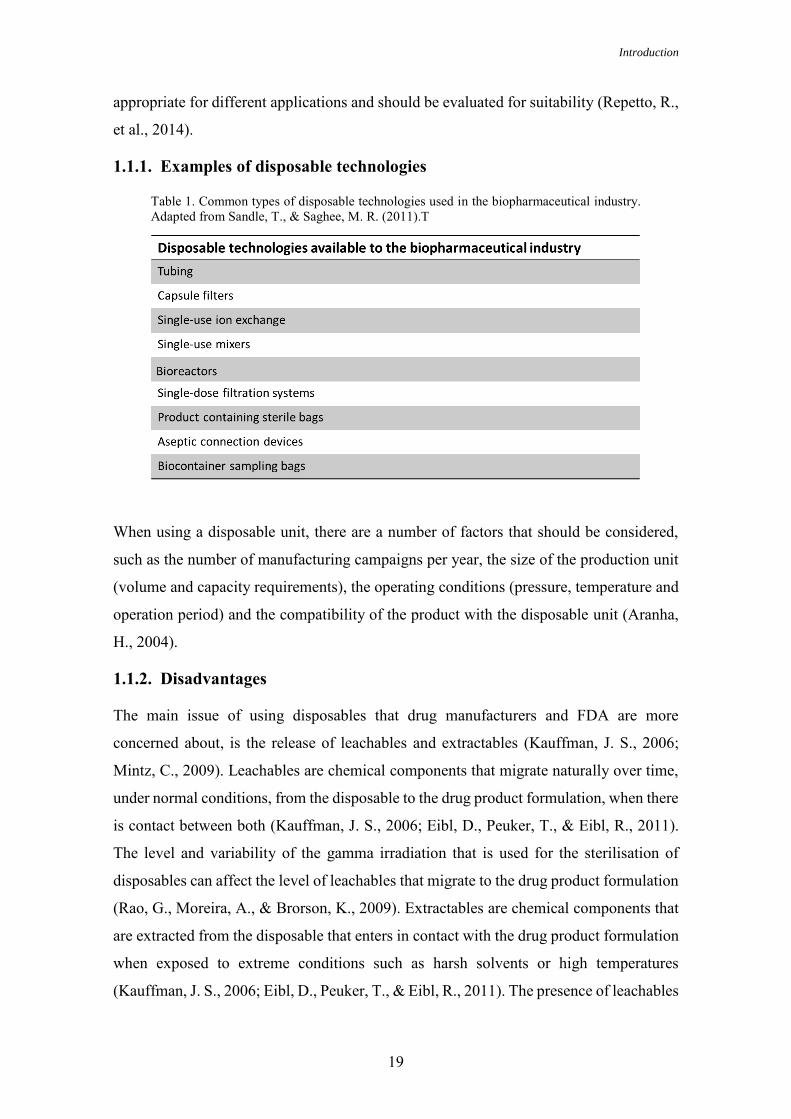
Table 1. Common types of disposable technologies used in the biopharmaceutical industry. Adapted from Sandle, T., & Saghee, M. R. (2011).T
When using a disposable unit, there are a number of factors that should be considered,
such as the number of manufacturing campaigns per year, the size of the production unit
(volume and capacity requirements), the operating conditions (pressure, temperature and
operation period) and the compatibility of the product with the disposable unit (Aranha,
H., 2004).
1.1.2. Disadvantages
The main issue of using disposables that drug manufacturers and FDA are more
concerned about, is the release of leachables and extractables (Kauffman, J. S., 2006;
Mintz, C., 2009). Leachables are chemical components that migrate naturally over time,
under normal conditions, from the disposable to the drug product formulation, when there
is contact between both (Kauffman, J. S., 2006; Eibl, D., Peuker, T., & Eibl, R., 2011).
The level and variability of the gamma irradiation that is used for the sterilisation of
disposables can affect the level of leachables that migrate to the drug product formulation
(Rao, G., Moreira, A., & Brorson, K., 2009). Extractables are chemical components that
are extracted from the disposable that enters in contact with the drug product formulation
when exposed to extreme conditions such as harsh solvents or high temperatures
(Kauffman, J. S., 2006; Eibl, D., Peuker, T., & Eibl, R., 2011). The presence of leachables

Design/Optimization/Introduction of Disposables for Biotech Drug Product Processes
20
and/or extractables can modify the safety, quality, identity, strength or purity of the drug
products. Therefore, the FDA offers guidance for protection against leachables and
extractables (Kauffman, J. S., 2006).
1.1.3. Advantages
The adoption of disposables has been increasing due to a variety of advantages over
traditional stainless steel systems, which include: decreased risk of cross-contamination,
increased assurance of sterility, safety considerations, process efficiencies, cost saving
and others (Aranha, H., 2004, Mintz, C. 2009; Sandle, T., & Saghee, M. R., 2011).
Cross-contamination
Cross contamination might result from microbiological contamination that can be
transferred from one batch to another, and from product adulteration, which means that
chemical residues can also be transferred from one batch to another. Disposables decrease
the risk of cross-contamination because they are single used and consequently not used
for further operations (Sandle, T., & Saghee, M. R., 2011).
Sterility assurance
The assurance of sterility is achieved due to a reduction of cross-transference of
microorganisms that diminishes the risk of environmental microbial contamination and
also due to a reduction of inadequate sterilisation cycles. The use of disposables avoid
cross contamination since the need to clean components disappears, thus reducing manual
handling. In addition, it allows the pharmaceutical companies to distance themselves from
equipment that needs to be sterilized or offer a risk with their transfer to clean rooms. A
reduction of microbial contamination is also achieved since structural integrity tests
(testing for leaks) of disposable technologies are also made by the manufacturers and by
the pharmaceutical company (Sandle, T., & Saghee, M. R., 2011; Jenness, E., & Gupta,
V., 2011; Repetto, R., et al., 2014).
Safety considerations
The use of disposables is safe for the product and for the operator. On one hand, it is safe
for the product because it reduces cross contamination as it is single used. In addition, the
potential for microbial contamination is decreased because the intervention of the
operator is less dependent since there is a reduction in assembly and handling of the
system. On the other hand, it is safe for the operator to use single use systems when he

Introduction
21
manipulates cytotoxic drugs, so called highly potent drugs or radiolabeled chemicals. The
handling of the operator with hazardous active pharmaceutical ingredients (API) is
diminished because single use systems don’t need clean in place (CIP) and sterilization
in place (SIP) operations. Thus, disposable systems protect the operator from materials
that can compromise his health and are in the best interest of manufacturing personnel
(Aranha, H., 2004; Sandle, T., & Saghee, M. R., 2011).
Process efficiencies
The use of disposables has advantages with regard to process efficiencies in comparison
with reusable stainless steel systems. Reusable stainless steel systems lead to equipment
support and routine inspections that need labour, time, effort and money. With the use of
disposables labour and time can be saved by decreasing operator dependence so that
operators and other resources can be used for other tasks. Disposables also reduce process
downtime and eliminate CIP and SIP, which save time, energy and costs. Time is also
saved because qualification and validation are facilitated (Aranha, H., 2004; Eibl, D.,
Peuker, T., & Eibl, R., 2011). Moreover they save waste disposal and quantities of
detergents and other cleaning chemicals that are used. The most important advantage is
faster turnaround times. There is a reduction of the time taken to obtain a new batch ready
for processing (Aranha, H., 2004; Mintz, C. 2009; Sandle, T., & Saghee, M. R., 2011).
Costs savings
One of the reasons that explain cost savings is the elimination of contamination events
that lead to batch rejection and process downtime (Eibl, D., Peuker, T., & Eibl, R., 2011).
Additionally, costs are reduced given that smaller batch sizes are possible to produce.
Disposable technologies are also capable to operate outside the clean rooms, which are
expensive (Valle, C., 2009). The costs are also reduced since the use of expansive
cleaning procedures (corrosive chemicals, water for injection and sterilization
procedures) are no longer required as disposables are pre-sterilized and discarded (Eibl,
D., Peuker, T., & Eibl, R., 2011). With the use of disposables there is also a reduction of
costs in installation, in process qualification and validation and in maintenance
requirements (Wong, R., 2004; Eibl, D., Peuker, T., & Eibl, R., 2011; Sandle, T., &
Saghee, M. R., 2011).

Design/Optimization/Introduction of Disposables for Biotech Drug Product Processes
22
Therefore, the use of disposable technologies not only increases quality since these
technologies decrease cross contamination, assure sterility and are safer but also reduces
costs and time.
1.1.4. Qualification and Validation
GMP regulations that are involved with the production of drugs and active pharmaceutical
ingredients (API´s) are supported by the FDA regulations 21 CFR Parts 210 and 211 and
internationally they are supported by the European Union directive 356 (Day, N., 2004).
Disposable technologies are manufactured according to cGMP, and must be qualified and
validated to guarantee that the equipment is not reactive, additive or absorptive, which is
important to assure that the safety, identity, strength, quality or purity of the API is not
affected (CFR, 2014).
Disposable technologies are manufactured with pharmaceutical grade polymeric
materials that are tested to meet the requirements of USP<87>, USP<88>, USP<661>
ISO 10993 and EP <3.1.9> (Creasey, J. & Thibion, V., 2013; Mueller, D., 2014). The
qualification and validation methods have to demonstrate that the disposable is reliable,
robust and safe (Belongia, B. M., & Allay, J. A., 2006).
Single use systems are sterilized with gamma irradiation, which can decrease the shelf
life of disposables and can accelerate the degradation of the polymeric substances.
Qualification tests must be done to determine the effects of irradiation and the stability of
the polymer used. Some qualification tests are (Aranha, H., 2004; Jornitz, M. W., Cappia,
J.-M. & Meltzer, T. H., 2009; Jornitz, M. W., Szarafinski, D., & Peuker, T., 2012;
Mueller, D., 2014):
Biocompatibility testing:
o USP ‹87› biological reactivity tests, in vitro,
o USP ‹88› biological reactivity tests, in vivo.
Mechanical properties:
o tensile strength,
o elongation at break,
o seal strength,
o air leak test.
Gas transmission properties:
o ASTM D3985: oxygen,

Introduction
23
o ASTM F1249: water vapour.
USP ‹661› test for plastics.
European Pharmacopeia (EP) <3.1.7.>: Ethylene vinyl acetate (EVA) for containers
and tubing.
European Pharmacopeia (EP) <3.1.9.>: Silicone elastomers for closures and tubing.
European Pharmacopeia (EP) <5.2.8.>: Minimizing the risk of transmitting animal
spongiform encephalopathy agents via human and veterinary medicinal products.
Total organic carbon (TOC) analysis.
pH and conductivity.
Extractable and leachable tests with standard solutions.
Chemical compatibility testing.
Protein adsorption studies.
Endotoxin testing.
Gamma irradiation sterilization validation.
Bacterial ingress test.
These tests are performed by the disposable technologies manufacturer under standard
setting and solutions, so they only serve as guidance for the pharmaceutical company that
buys the disposable technologies. Thus, before implementing the disposable technologies
in the manufacturing process, the system users must validate them under specific
requirements and process conditions (Aranha, H., 2004; Jornitz, M. W., Cappia, J.-M. &
Meltzer, T. H., 2009; Jornitz, M. W., Szarafinski, D., & Peuker, T., 2012).
1.1.5. Environmental impact
The balance of ecosystems can be significantly affected by human activities and therefore
have health, aesthetic and economic consequences to us. Consequently, sustainability is
an important issue and companies must respect laws and regulations that are related to
their business activities (Whitford, W. G., 2014). Companies should provide information
on the environmental impact and sustainability of their manufacturing systems (Rawlings,
B., & Pora, H., 2009). The environmental evaluation can be enabled through guidelines
from industrial organization (ex: Bio Process Systems Alliance (BPSA)), regulatory
guidelines and directives, data from suppliers and manufacturers and published articles,
reviews, and case studies (Rawlings, B., & Pora, H., 2009).

Design/Optimization/Introduction of Disposables for Biotech Drug Product Processes
24
Table 2. Recycling advantages and constraints. Adapted from Pora, H., & Rawlings, B. (2009).
The environmental impact of disposable technologies has become a concern in recent
years (Rawlings, B., & Pora, H., 2009; Pora, H., & Rawlings, B., 2009). Thus,
manufacturers should choose recyclable materials of construction for disposable systems
instead of using materials made from non-renewable feedstocks (Rao, G., Moreira, A., &
Brorson, K., 2009). Disposable systems should be designed and manufactured to ensure
a minimum environmental impact and a maximum recyclability of waste (Rao, G.,
Moreira, A., & Brorson, K., 2009; Pora, H., & Rawlings, B., 2009).
Another concern is the environmental impact of currently used disposal methods, which
should consider the legislation in force to protect the environment and guarantee
industrial sustainability. There are three major solid-waste disposal methods for
disposable systems: 1) recycling options, which include the reuse of components, the
reprocessing of recycled material and the production of liquid fuel; 2) incineration, with
or without energy recovery; 3) landfills (non-hazardous waste, hazardous waste). The
following tables summarize the advantages and constraints of the methods above
mentioned (Pora, H., & Rawlings, B., 2009):

Introduction
25
Table 4. Landfill advantages and constraints. Adapted from Pora, H., & Rawlings, B. (2009).
Table 3. Incineration advantages and constraints. Adapted from Pora, H., & Rawlings, B. (2009).
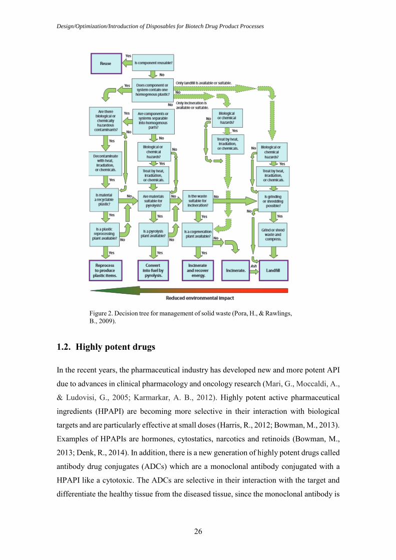
Taking into account the three disposal methods presented, the optimal choice would be
the one with the lowest environmental impact. In order to help making this choice, a
decision tree can be used, as shown below (Pora, H., & Rawlings, B., 2009):
Design/Optimization/Introduction of Disposables for Biotech Drug Product Processes
26
Figure 2. Decision tree for management of solid waste (Pora, H., & Rawlings, B., 2009).
1.2. Highly potent drugs
In the recent years, the pharmaceutical industry has developed new and more potent API
due to advances in clinical pharmacology and oncology research (Mari, G., Moccaldi, A.,
& Ludovisi, G., 2005; Karmarkar, A. B., 2012). Highly potent active pharmaceutical
ingredients (HPAPI) are becoming more selective in their interaction with biological
targets and are particularly effective at small doses (Harris, R., 2012; Bowman, M., 2013).
Examples of HPAPIs are hormones, cytostatics, narcotics and retinoids (Bowman, M.,
2013; Denk, R., 2014). In addition, there is a new generation of highly potent drugs called
antibody drug conjugates (ADCs) which are a monoclonal antibody conjugated with a
HPAPI like a cytotoxic. The ADCs are selective in their interaction with the target and
differentiate the healthy tissue from the diseased tissue, since the monoclonal antibody is
Introduction
27
joined to the HPAPI by a short linker molecule, which is designed to break down at the
active site and release the cytotoxic (Bormett, D., 2008; Lonza, 2012; Wooge, C., 2014)
Every API must be evaluated and classified to assess potential toxicity, potency and
potential hazards so that the level of containment that is required can be determined
(Bormett, D., 2008). The drug substances can be classified according to their potency
based on the use of occupational exposure limits (OEL) or occupational exposure bands
(OEB) (Calkins, T., 2010; Wollowitz, S., 2010; Harris, R., 2012). The OEL is given in
microgram (µg) per cubic meter (m3) or milligram (mg) per cubic meter (m3) and as the
most likely and toxic route is by inhalation it is defined as the air concentration of the
compound that can be inhaled by a worker over an 8h working day, 40 hours a week
without adverse effects (Wollowitz, S., 2010; Denk, R., 2014). A lower value of OEL
means a more potent compound which requires a higher level of containment (Van
Arnum, P., 2009). The OEB group together substances by an approximate hazard level
and this dictate the handling containment required to work with the substances
(Wollowitz, S., 2010; Bowman, M., 2013). In the last years, a number of systems have
been proposed to classify APIs (Harris, R., 2012). The industry uses different category
systems ranging from three to six - category systems (Farris, J. P., Ader, A. W., & Ku, R.
H., 2006; Calkins, T., 2010). There are also companies that developed their own category
system, according to their equipment and facilities (Bowman, M., 2013). There are
different category systems because companies have different products, facilities,
equipment and processes (Farris, J. P., Ader, A. W., & Ku, R. H., 2006). The system that
is more frequently used is the four category system, the SafeBridge System and its
evaluation and categorisation are described in table 5 (Farris, J. P., Ader, A. W., & Ku,
R. H., 2006; Harris, R., 2012; Bowman, M., 2013).
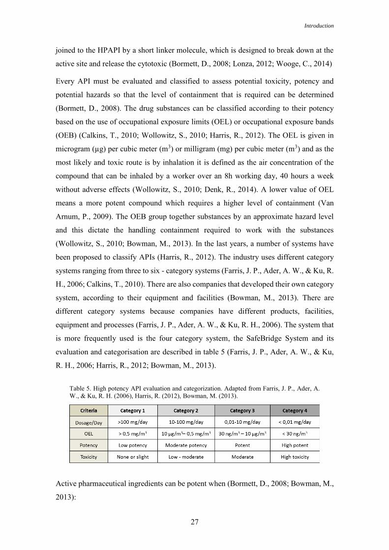
Active pharmaceutical ingredients can be potent when (Bormett, D., 2008; Bowman, M.,
2013):
Table 5. High potency API evaluation and categorization. Adapted from Farris, J. P., Ader, A. W., & Ku, R. H. (2006), Harris, R. (2012), Bowman, M. (2013).

Design/Optimization/Introduction of Disposables for Biotech Drug Product Processes
28
1. The active pharmaceutical ingredient has an OEL of ≤ 10 µg/m3 of air as an 8
hour time weighted average.
2. The active pharmaceutical ingredient has a therapeutic dose of ≤ 10 mg/day.
3. The dose of 1 mg/kg/day of active pharmaceutical ingredient produce serious
toxicity in laboratory animals.
4. The active pharmaceutical ingredient has high selectivity and/or has the potential
to cause cancer, mutations, developmental effects or reproductive toxicity at low
doses.
5. It is a novel compound of unknown toxicity.
The handling with highly potent active pharmaceutical ingredients requires a substantial
investment in specialized containment to guarantee that workers and the working
environment are protected from exposure (Bormett, D., 2008). A safe handling with
highly potent active pharmaceutical ingredients can be achieved by using standard
operating procedures (SOPs), trained workers, containment equipments, personal
protective equipment, process isolation, facility design and cGMP activities (Bormett, D.,
2008; Karmarkar, A. B., 2012).
1.2.1. Facility design
Handling with highly potent active pharmaceutical ingredients requires specialized
equipment to achieve containment and attention to safety. A facility should be designed
with equipment such as isolators with laminar flow hoods and appropriate ventilation for
potent compound handling to protect workers and to maintain the product sterile. The
room pressure should be negative to its surrounding rooms to guarantee that the potent
products are retained in the working environment. The air should also be filtrated so that
escaping product is captured before its release to the external environment. To prevent
cross contamination or concentration of materials, the airflow in the facility must be
single pass. Process isolation and containment equipment are very important to ensure
that an entire manufacturing process is carried out in closed systems (from raw materials
to product packaging) so that the chances of operators exposure can be minimized (Van
Arnum, P., 2009; Calkins, T., 2010; Wooge, C., 2014).
The facility design for ADCs has to take in consideration that the HPAPI must be
contained under negative pressure, but the antibody components and the final drug
product should be handled under positive pressure to prevent microbial and particle

Introduction
29
contamination. Therefore, the handling steps involving HPAPI should take place in an
isolator in a separate room, where the air is under negative pressure. HPAPIs can only
leave this room if they are in solution, because this removes the risk of airborne
contamination and the chances of operators or environment contamination are much
lower. The conjugation to an antibody occurs in a second room which is under positive
pressure and therefore protects the product from external contamination. The conjugation
reaction must still take place in a closed system that enables full containment of hazardous
materials, because despite being in solution HPAPIs are still hazardous (Calkins, T.,
2010; Wooge, C., 2014).
Disposable technologies are a suitable option for handling with HPAPIs as they can
improve containment. They protect and reduce the exposure of the operators from the
compounds, they eliminate the need for extensive cleaning that potent drugs require and
decrease cross contamination. The adoption of disposable technologies is of extreme
importance in order to avoid the present risk of contamination of HPAPI in multiproduct
facilities (Greb, E., 2010; Challener, C., 2014).
1.3. Cryo-vessel
Cryo-vessels are large-scale cryo-preservation systems made of stainless steel containers
from 50-300 L. They are divided in two compartments. The inner compartment contains
the API solution, whereas the outer compartment, named double coat is for the circulation
of silicon oil. They are systematically frozen and thawed with a well-controlled heat or
cold transfer fluid (silicon oil) that circulates in the outer compartment and goes in the
internal compartment through an inner tube snake with fins, which efficiently transfer
heat or cold into the solution (Arnitz, T., & Liebig, C., 2011; Kantor, A., MacMillan, S.,
Ho, K., Tchessalov, S., & Warne, N., 2011; Kolhe, P., & Badkar, A., 2013).
Cryo-vessels are used for freezing, storage, transport and thawing of API. The
temperature storage can range from liquid storage at 2 – 8 °C to frozen storage down to -
50 °C. The liquid storage from 2 - 8 °C can affect the quality and lead to degradation of
proteins. Therefore, frozen storage is indicated to guarantee a higher stability and longer
shelf life of proteins, decrease microbial growth and eliminate the foam formation during
transport (Webb, S. D., Webb, J. N., Hughes, T. G., Sesin, D. F., & Kincaid, A. C., 2002;
Arnitz, T., & Liebig, C., 2011; Kantor, A., Tchessalov, S., & Warne, N., 2011; Desu, H.
R., & Narishetty, S. T., 2013).

Design/Optimization/Introduction of Disposables for Biotech Drug Product Processes
30
As proteins lack stability when in solution, it was considered convenient since a long
time, to freeze them because of the need to store proteins for a large period of time. New
approaches to the freezing and storage of proteins have been developed in which the
freeze-thaw process is better controlled due to the emergence of large scale production of
proteins (Kantor, A., Tchessalov, S., & Warne, N., 2011).
Protein based API can be stored under a variety of conditions such as refrigerated liquids
and spray dried powders. However, a considerable number of clinical and commercial
API are stored in a frozen state (Kantor, A., Tchessalov, S., & Warne, N., 2011).
There are three types of container closure system normally used for frozen API: plastic
or stainless steel bottles between 1-5 L, plastic bags between 1-16 L and stainless steel
cryo-vessels between 50-300 L. Although there has been a development of the systems,
there is still a need for all these three systems depending on the nature of the drug
substance, its volume and storage temperature (Kantor, A., Tchessalov, S., & Warne, N.,
2011; Kolhe, P., & Badkar, A., 2013).
1.4. Tubings and Connectors
Nowadays the economic situation is an obstacle for the development of new drugs. As a
challenge, the pharmaceutical companies have to review their manufacturing systems and
find ways to make them more reliable, flexible and cost-effective. Therefore traditional
stainless steel equipment has been replaced by pre-sterilized disposable technologies
(Boehm, J., 2010).
1.4.1. Tubings
Flexible tubings have gained more acceptance in recent years due to its low costs
associated with validation, CIP and SIP (Spontak, R. J., & Patel, N. P., 2000; Colas, A.,
Malczewski, R., & Ulman, K., 2004).
Tubings are involved in the manufacturing of pharmaceuticals and are currently used for
fluid transfer, gas transfer, peristaltic pumping and filling operations. Tubings are made
from various polymeric materials that may vary according to polymer class, molecular
weight and additives. This variability confers a wide range of performance characteristics
on the plastic materials. Examples of plastics that are commonly used are silicone and
thermoplastic elastomer (Colas, A., 2001; Aranha, H., 2004).

Introduction
31
Silicone can have diverse applications: as excipients in topical formulation, as excipients
in controlled devices and in pharmaceutical manufacturing for siliconisation, as antifoam
and for tubing. Silicone tubings are used in pharmaceutical manufacuturing operations
for transfer processes. Two types of silicone tubings may be used: platinum-cured silicone
tubings or peroxide-cured silicone tubings. It is preferable to use platinum-cured silicone
tubings since it is naturally purer and it offer fewer leachables and extractables; they have
smoother internal surfaces and it minimizes protein loss due to adhesion. Moreover
peroxide cured tubings contain peroxide by-products that can be released and contaminate
the transferred product (Colas, A., 2001, Aranha, H., 2004; AdvantaPure, 2013). The
platinum-cured silicone tubings can have different applications such as in ultra-pure fluid
transfer or in peristaltic pumps, where durability is required or in high/low pressure
applications (Dow Corning).
Tubings that can be heat sealed and welded are often needed at some point in the fluid
path. Instead of using multiple materials in the different sections of the fluid path since
not all materials have the required characteristics (for example: heat sealed and welded
capacity), a material that meets the needed requirements of the customer can be selected.
Tubing materials such as thermoplastic elastomer (combine the material properties of
rubbers and plastics) meet the conditions that are often required.This kind of tubing is
flexible, has a high purity, is less permeable and is a peristaltic pump tubing that may be
welded and sealed, thus eliminating the use of multiple materials in a fluid path
(AdvantaPure, 2013). Thermoplastic elastomer can be divided in two groups: multiblock
copolymers which consist of soft elastomers and hard thermoplastic blocks such as
thermoplastic polyurethane and blends (Shanks, R., & Kong, I., 2012).
Table 6. Example of plastic used for tubing (Silicone). Adapted from Repetto, R., et al. (2014).

Design/Optimization/Introduction of Disposables for Biotech Drug Product Processes
32
Other plastics that can be used for tubing:
Table 7. Example of plastics used for tubing (Thermoplastic elastomer). Adapted from Repetto, R., et al. (2014).
Table 9. Examples of plastics used for tubing (Fluoropolymers). Adapted from Repetto, R., et al. (2014).
Table 8. Example of plastic used for tubing (Copolymer). Adapted from Repetto, R., et al. (2014).

Introduction
33
In the cGMP environment flexible tubing has to be qualified and validated. So, the tubing
that are considered for single use application as well as for multiple use application need
to meet FDA, ISO, USP, EP and ASTM standards. In case of an inspection in the US it
is sufficient that the tubing meet the US standards and in case of an inspection in the
Europe it is sufficient that the tubing meet the Euopean standards. Therefore, according
to the country where it is manufactured and according to the delivery country the
following standards should be fulfilled (Colas, A., Malczewski, R., & Ulman, K., 2004;
Hunt, D. G., 2013; Mueller, D., 2014):
US standards:
FDA G95-1 Memorandum: Required Biocompatibility Training and Toxicology
Profiles for Evaluation of Medical Devices.
FDA 21 CFR 177.2600: Rubber articles intended for repeated use.
USP <85>: Bacterial Endotoxins Test.
USP <87>: Biological Reactivity Tests, In Vitro.
USP <88>: Biological Reactivity Tests, In Vivo, Classification of Plastics: Class V
and VI.
USP <1663>: Extractables.
USP <1664>: Leachables.
ASTM F748-98: Standard Practice for Selecting Generic Biological Test Methods for
Materials and Devices.
International standards:
ISO 10993: Biological Evaluation of Medical Devices, Part 1: Evaluation and Testing.
ISO 10993: Biological Evaluation of Medical Devices, Part 5: Tests for in vitro
cytotoxicity.
ISO 10993: Biological Evaluation of Medical Devices, Part 11: Tests for systemic
toxicity.
European standards:
EP <3.1.9>: Silicone elastomers for closures and tubing.
EP <3.2.2>: Plastic containers and closures for pharmaceutical use.
Design/Optimization/Introduction of Disposables for Biotech Drug Product Processes
34
ASTM F748-98: Standard Practice for Selecting Generic Biological Test Methods for
Materials and Devices.
1.4.2. Connectors
Many of the advantages of disposable technologies would be lost if manufactures could
not safely connect systems to create an aseptic process, once a connector can be the
determining factor in keeping a process strictly aseptic (Boehm, J., 2010).
The risk of contamination requires special attention in biopharmaceutical processes since
almost every biopharmaceutical process implicates making sterile connections between
fluid pathways. Traditionally, reusable fittings have been used, particularly those made
of stainless steel (e.g. a stainless steel tri-clamp), but the tendency is towards the use of
disposable connectors (Mach, C. J., & Riedman, D., 2008).
A wide variety of connectors are commercially available and the right choice depends on
the needs and preferences of a given facility and customer (Boehm, J., 2010).
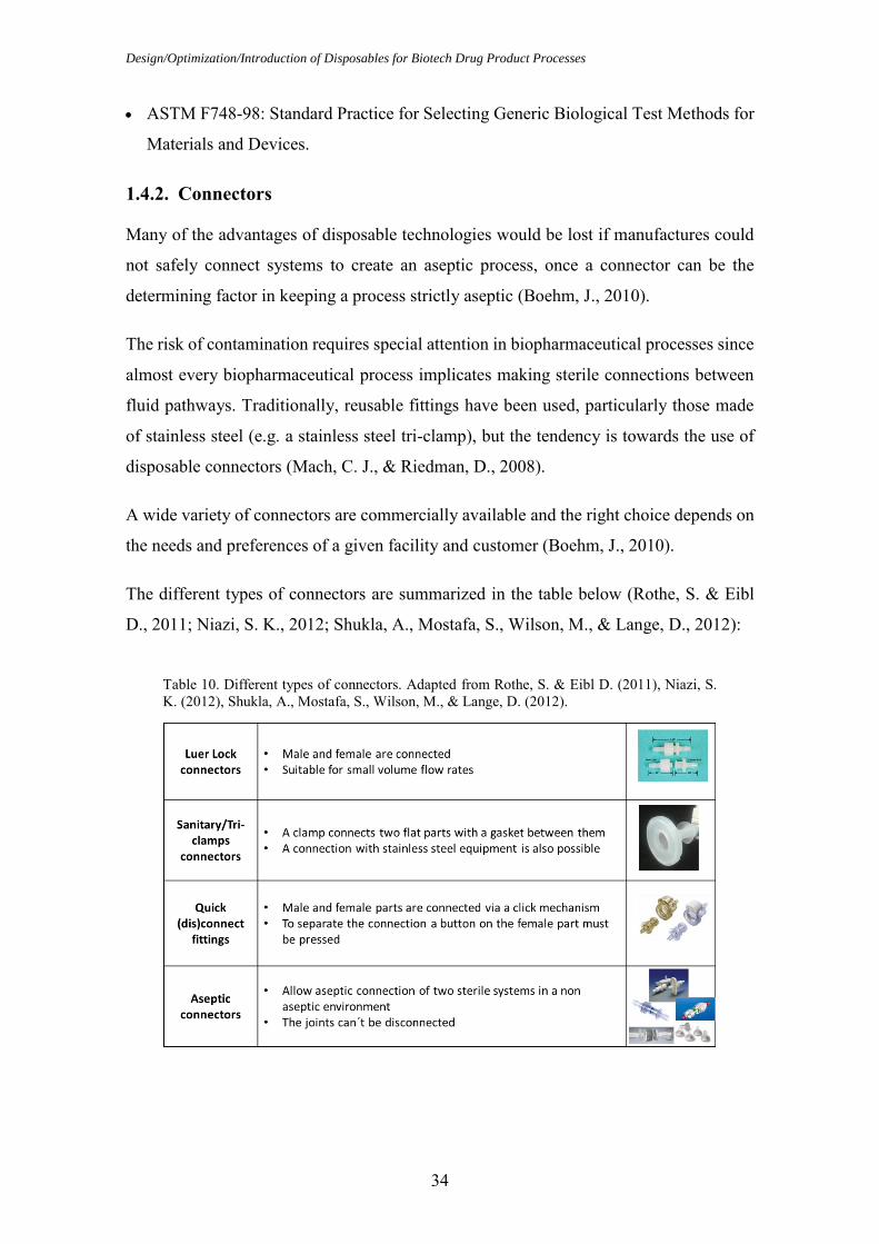
The different types of connectors are summarized in the table below (Rothe, S. & Eibl
D., 2011; Niazi, S. K., 2012; Shukla, A., Mostafa, S., Wilson, M., & Lange, D., 2012):
Table 10. Different types of connectors. Adapted from Rothe, S. & Eibl D. (2011), Niazi, S. K. (2012), Shukla, A., Mostafa, S., Wilson, M., & Lange, D. (2012).

Introduction
35
There are different systems for aseptic connection:
1. Connection under laminar flow hood or in a clean room area class A:
Luer-lock connectors, tri-clamps and quick (dis)connect connectors provide fast and easy
connections and should be used together with laminar flow hood. Careful handling with
this type of connectors is needed to prevent contamination. Examples of this kind of
connectors are: tri-clamps and MPC® Series from Colder Company (Boehm, J., 2010;
Rothe, S. & Eibl D., 2011).
2. Sterilisation in place connectors:
These types of connectors create sterile connections between a range of disposable
systems and stainless steel equipment. They can be sterilized at the point of connection.
Examples of this kind of connectors are: Steam-Thru System® from Colder Company and
Lynx ST® from Millipore Company (Boehm, J., 2010; Rothe, S. & Eibl D., 2011).
3. Aseptic connectors
Aseptic connectors allow aseptic connection without laminar flow hood like conventional
connectors. These connectors are secure, the connections can be achieved rapidly without
any further support or additional equipment and permit a sterile fluid pathway in a non-
Figure 4. Quick-connectors: MPC® Series from Colder Company
Figure 6. Lynx ST® from Millipore Company
a) b)
Figure 3. Triclamp disposable (a) and a stainless steel clamp (b)
Figure 5. Steam-Thru System® from Colder Company

Design/Optimization/Introduction of Disposables for Biotech Drug Product Processes
36
aseptic environment (gray space). The aseptic parts on the connector side are sealed with
sterile membrane filters or caps. After coupling, the sterile membrane filters or caps must
be removed and both parts have to be clamped or fixed. The connection is then ready for
use. It is not possible to disconnect connectors that are once connected. Examples of this
kind of connectors are: Kleenpak KPC® by Pall, Lynx S2S® by Millipore, Opta SFT-1®
by Sartorius Stedim Biotech, ReadyMate DAC® by GE and the Pure-Fit SC® by Saint-
Gobain (Strahlendorf, K. A., & Harper, K., 2009; Boehm, J., 2010; Rothe, S. & Eibl D.,
2011).
The variety of plastics and connectors enables the development of innovative equipment
and provides customization.
Figure 9. Opta SFT-1® by Sartorius Stedim Biotech
Figure 11. Pure-Fit SC® by Saint-Gobain
Figure 8. Lynx S2S® by Millipore
Figure 10. ReadyMate DAC® by GE
Figure 7. Kleenpak KPC® by Pall

Introduction
37
1.5. Fluid transfer
In the manufacturing process the fluid can be transferred either by pump systems or by
pressurizing (Kubischik, J. & Schaupp, M., 2011).
1.5.1. Pump systems
Pumps can be classified in two types: positive displacement pumps and rotodynamic
pumps. Both types are designed to transfer fluids but the way this is accomplished differs
(Srinivasan, K. M., 2008).
A positive displacement pump moves the same amount of fluid for each rotating cycle of
the system. It uses mechanisms that seals fluid in a chamber and forces it out by reducing
the volume of the chamber. This action increases the fluid pressure. The motion can be
rotary or reciprocating (Srinivasan, K. M., 2008; Gupta, A. K. & Arora, S. K., 2013).
In a rotodynamic pump there is a free passage of fluid between the inlet and outlet of the
machine without sealing. Rotodynamic pumps have a rotating part called impeller, which
rotates the fluid continuously and transfers energy from the rotor to the fluid (Garde, R.
J., 1997; Gupta, A. K. & Arora, S. K., 2013).
Piston pumps have been a traditional technology in pharmaceutical technology. However
due to stricter validation requirements and design innovations peristaltic pumps started to
be considered instead of piston pumps (Lambert, P., (2008).
Figure 12. Classification of pumps. Adapted from Srinivasan, K. M. (2008).

Design/Optimization/Introduction of Disposables for Biotech Drug Product Processes
38
Piston pump
A piston pump is a positive displacement pump. It is a mechanical device that cycles
through a suction phase and a pressure phase to move fluid. Internal parts of a piston
pump (gaskets, seals, valves and internal surfaces) are in direct contact with the fluid.
Piston pumps are known for their reliability and accuracy. However, they require regular
maintenance and disassembly for cleaning and sterilization and cross contamination
between batches is a concern. In addition, they also apply high pressure and high shear
forces, that are inappropriate for biological drugs which are shear sensitive (Lambert, P.,
2008).
Peristaltic pump
A peristaltic pump is also a positive displacement pump. In this pump type the fluid is
moved forward by progressively squeezing and releasing the flexible tubing (Avis, K. E.
(Ed.) 1995; Lipták, B. G. (Ed), 2003; Volk, M., 2014). The product only comes in contact
with the flexible tubing. For this reason peristaltic pumps can be used for single aseptic
processes (Lambert, P., 2008).
Peristaltic pumps using disposable tubes eliminate the possibility of cross contamination
and the cleaning of the pump isn't required since the tubing is the only part that comes
into contact with the fluid (Lipták, B. G. (Ed), 2003; Niazi, S. K., 2012). It also can be
used with some biological drugs that are shear sensitive, since they apply low pressure
and provide a gentle handling (Niazi, S. K., 2012). However, studies have shown that
some tubing materials release particles (spalling) during the use with peristaltic pumps,
due to their poor abrasion resistance and consequently, contaminating the solution (Bahal,
S. M., & Romansky, J. M., 2002; Colas, A., Malczewski, R., & Ulman, K., 2004).
1.5.2. Pressurizing
Fluids can be transferred by using pressurized gas or vacuum, when pumps are not
available, when their use might cause contamination or degradation due to mechanical
shear or when handling abrasive or corrosive materials, thus avoiding pumping the
materials. Pressurized systems use nitrogen, air or other gas under moderate to high
pressure to force the transfer of the fluid (CCPS, 1993; Kerry, F. G., 2007).

Introduction
39
1.6. Influence of Pump systems and Pressurizing in protein solutions
In some cases, during manufacturing, proteins undergo a variety of stresses leading to
physical and chemical instability that can compromise the quality, safety and efficiency
of the proteins, such as monoclonal antibodies and the yield of the final drug product.
Physical instability causes changes in the higher order structure of proteins (secondary,
tertiary or quaternary structure), which include denaturation, aggregation, precipitation or
adsorption to surfaces. Chemical instability is a covalent modification of the protein via
bond formation or cleavage (Banga, A. K., 2005; Bausch, U. J., 2008; Vázquez-Rey, M.,
& Lang, D. A., 2011; Ma, J. K., & Hadzija, B., 2013).
Protein aggregation can be induced by various processing steps during manufacture such
as pumping and pressurization (Vázquez-Rey, M., & Lang, D. A., 2011).
Pumping processes expose proteins to mechanical shear forces that can cause protein
aggregation and formation of particles. However, the extent of impact depends on the
intensity and on the duration of exposure to such stress. Shearing creates a hydrophobic
air/water interface which results in the alignment of protein molecules at the interface.
The alignment of the protein molecules at the interface occurs since proteins denature
exposing the hydrophobic residues to the air, forming unfolded intermediates that induce
protein aggregation (Wang, W., 1999; Vázquez-Rey, M., & Lang, D. A., 2011; Ma, J. K.,
& Hadzija, B., 2013). To reduce shearing-induced protein aggregation, surfactants can be
used as they compete with the protein molecules for the hydrophobic interfaces by
binding directly to proteins or by increasing the viscosity of a protein solution limiting
the movement of proteins (Wang, W., Nema, S., & Teagarden, D., 2010). Certain pumps
like piston pumps and peristaltic pumps can form protein particles (for example white
tornadoes) due to shear. However, peristaltic pumps generate less protein particles as
piston pumps (Bausch, U. J., 2008; Roche Internal Report, 2008; Nayak, A., Colandene,
J., Bradford, V., & Perkins, M., 2011).
Despite peristaltic pumps being advertised to be used with biological drugs that are shear
sensitive, it was shown that they also can form protein aggregation and protein particles
due to shear forces (Maggio, E. T., 2008). Some authors correlate the formation of protein
aggregation with the material of the tubing (Thomas, C. R., & Geer, D., 2010, Vázquez-
Rey, M., & Lang, D. A., 2011).

Design/Optimization/Introduction of Disposables for Biotech Drug Product Processes
40
The formation of aggregates due to pumping can also be minimized using pressure for
the transfer of fluids (Vázquez-Rey, M., & Lang, D. A., 2011).
Low to moderate pressures exert no significant effect on the aggregation of proteins.
However, high pressure can cause protein denaturation and facilitate protein aggregation
due to increased hydrophobic interactions. The pressure-induced protein aggregation has
not been a major problem in the manufacturing of proteins therapeutics since the pressure
that is required to unfold proteins must be greater than 100 MPa, which is beyond the
range of routine exposure (Chang, B. S., & Yeung, B., 2010; Wang, W., Nema, S., &
Teagarden, D., 2010; Meersman, F., Daniel, I., Bartlett, D. H., Winter, R., Hazael, R., &
McMillain, P. F., 2013).

Target
41
2. Target
The purpose of this master thesis is to test the possibility to transfer API solutions with
peristaltic pump and overpressure in combination with a combined thawing and transfer
disposable tube and to verify if it is advantageous to replace the current thawing and
transfer disposable tubes used in the API thawing and drug product compounding process
by a new combined thawing and transfer disposable tube in order to diminish the quality
risks of manual handling, reduce assembling time and improve safety of ADCs.
With that purpose in mind, a series of practical experiments will be performed, which
consist of testing three different combined thawing and transfer disposable tubes with two
methods for moving fluid: peristaltic pump and overpressure. Testing a new combined
disposable with overpressure and additionally, using a peristaltic pump for the transfer of
API solution would be innovative in the methods used in Roche Diagnostics GmbH,
Mannheim drug product compounding processes, since until today the only moving fluid
method used for transfer has been overpressure with a specific tube with pressure
capabilities. In addition, the transfer speeds will be calculated, the length and diameter of
the tubes will be measured and the whole handling process evaluated in order to compare
their benefits and disadvantages from the quality and efficiency perspective.

Design/Optimization/Introduction of Disposables for Biotech Drug Product Processes
42
3. Types of Cryo-vessels
Roche Diagnostics GmbH, Mannheim operates with three different types of cryo-vessels,
namely US (United States Cryo-vessel), Basel and Penzberger (European Cryo-vessels).
3.1. US Cryo-vessel Type
Two sizes of US Cryo-vessel are used: 120 L (small vessel) and 300 L (big vessel).
Figure 13. US Cryo-vessel type: Filling, Thawing and Transfer processes
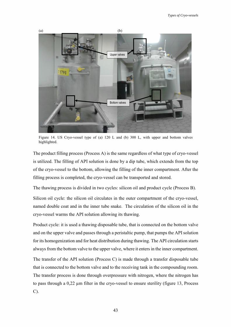
Types of Cryo-vessels
43
The product filling process (Process A) is the same regardless of what type of cryo-vessel
is utilized. The filling of API solution is done by a dip tube, which extends from the top
of the cryo-vessel to the bottom, allowing the filling of the inner compartment. After the
filling process is completed, the cryo-vessel can be transported and stored.
The thawing process is divided in two cycles: silicon oil and product cycle (Process B).
Silicon oil cycle: the silicon oil circulates in the outer compartment of the cryo-vessel,
named double coat and in the inner tube snake. The circulation of the silicon oil in the
cryo-vessel warms the API solution allowing its thawing.
Product cycle: it is used a thawing disposable tube, that is connected on the bottom valve
and on the upper valve and passes through a peristaltic pump, that pumps the API solution
for its homogenization and for heat distribution during thawing. The API circulation starts
always from the bottom valve to the upper valve, where it enters in the inner compartment.
The transfer of the API solution (Process C) is made through a transfer disposable tube
that is connected to the bottom valve and to the receiving tank in the compounding room.
The transfer process is done through overpressure with nitrogen, where the nitrogen has
to pass through a 0,22 µm filter in the cryo-vessel to ensure sterility (figure 13, Process
C).
(a)
Figure 14. US Cryo-vessel type of (a) 120 L and (b) 300 L, with upper and bottom valves highlighted.
(b)
Bottom valves
Upper valves

Design/Optimization/Introduction of Disposables for Biotech Drug Product Processes
44
3.2. Basel and Penzberger Cryo-vessel Types
The Basel and Penzberger Cryo-vessel types only exist with the capacity of 300 L. They
differ from each other in the localization of the upper valve and the dip tube.
Figure 15. Basel and Penzberger Cryo-vessel: Filling, Thawing and Transfer processes
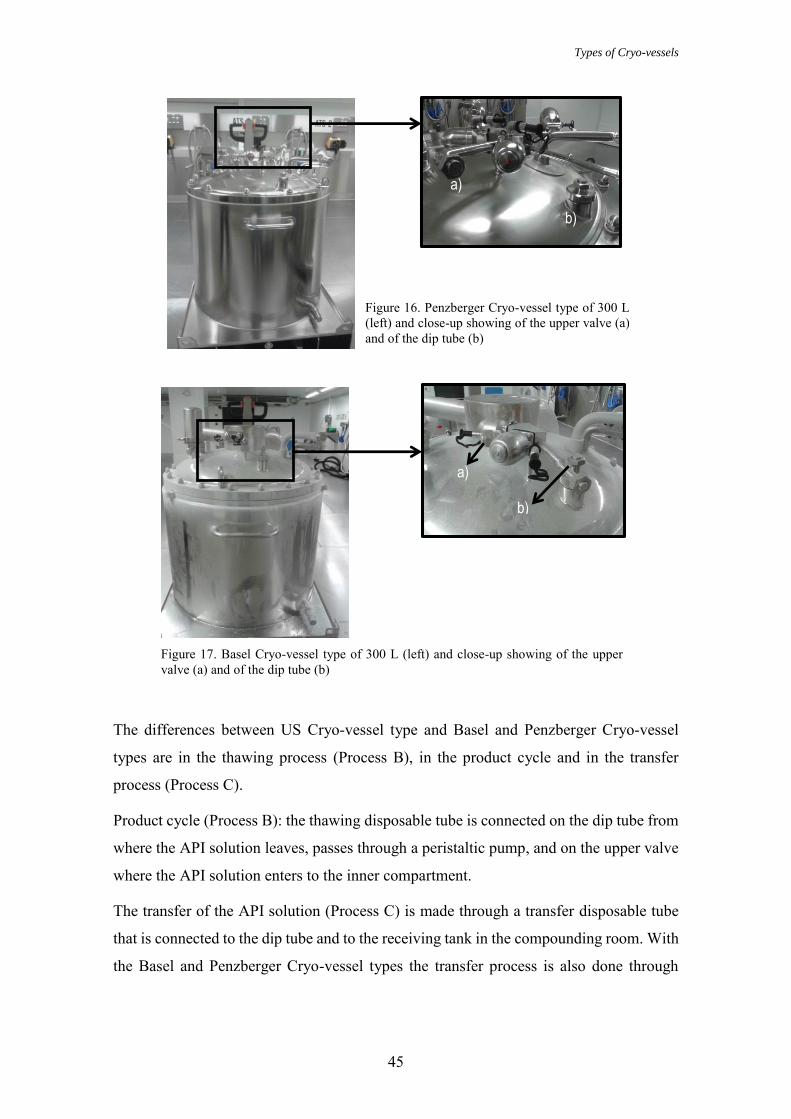
Types of Cryo-vessels
45
The differences between US Cryo-vessel type and Basel and Penzberger Cryo-vessel
types are in the thawing process (Process B), in the product cycle and in the transfer
process (Process C).
Product cycle (Process B): the thawing disposable tube is connected on the dip tube from
where the API solution leaves, passes through a peristaltic pump, and on the upper valve
where the API solution enters to the inner compartment.
The transfer of the API solution (Process C) is made through a transfer disposable tube
that is connected to the dip tube and to the receiving tank in the compounding room. With
the Basel and Penzberger Cryo-vessel types the transfer process is also done through
a)
b)
Figure 16. Penzberger Cryo-vessel type of 300 L (left) and close-up showing of the upper valve (a) and of the dip tube (b)
Figure 17. Basel Cryo-vessel type of 300 L (left) and close-up showing of the upper valve (a) and of the dip tube (b)
a)
b)

Design/Optimization/Introduction of Disposables for Biotech Drug Product Processes
46
overpressure with nitrogen where the nitrogen has to pass through a 0,22 µm filter in the
cryo-vessel to ensure sterility (see figure 15 – Process C).

Today’s Cryo-vessel process cycle (API), Roche Mannheim
47
4. Today’s Cryo-vessel process cycle (API), Roche Mannheim
Figure 18. Today’s Cryo-vessel process cycle in Roche Diagnostics GmbH, Mannheim

Design/Optimization/Introduction of Disposables for Biotech Drug Product Processes
48
5. Today’s API thawing and transfer process
Before starting the thawing process the thawing disposable tube must be attached to the
cryo-vessel in a class C room. The thawing disposable tube length is approximately 4
meters (m) and must be cut with a sterilized scissor in two parts, one with the length of
approximately 3 m and the other with the length of approximately 1 m. Linked to the
thawing tube is a Nova Septum® bag for bioburden sampling and a syringe used for
endotoxins (LAL test) sampling. The polyethylene Nova Septum® bag was validated for
bioburden and the polycarbonate syringe was validated for endotoxins (Roche Internal
Document, 2010).
In a 2-8 °C room the thawing tube is connected to a peristaltic pump, which will allow
the thawing process, product cycle.
Figure 19. Today’s thawing tube (a) attached with a Nova Septum® and a syringe for sampling (b)
(a)
(b)
(b)
Figure 20. Upper valve of US Cryo-vessel (a) and connection of the thawing disposable tube with the upper valve before the thawing process (b)
(a) (b)
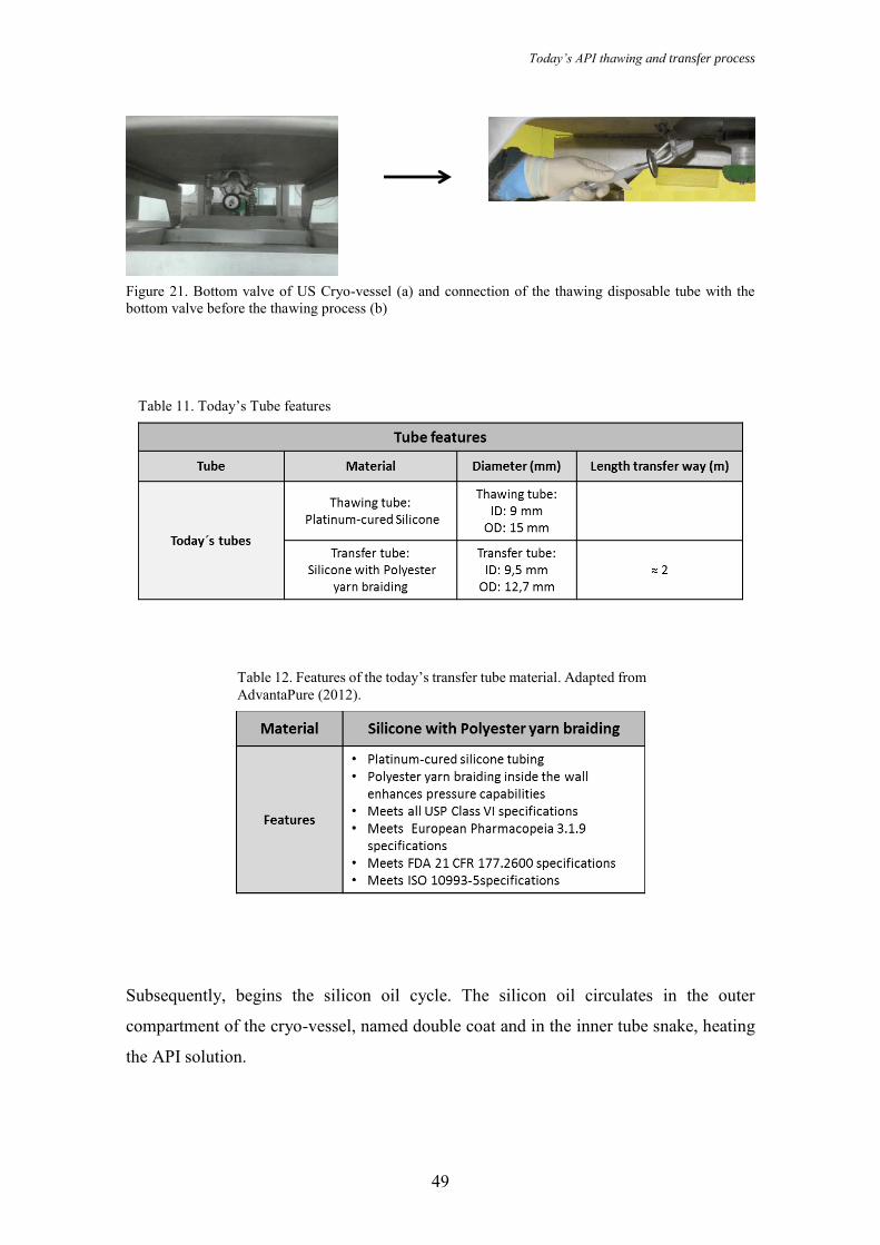
Today’s API thawing and transfer process
49
Subsequently, begins the silicon oil cycle. The silicon oil circulates in the outer
compartment of the cryo-vessel, named double coat and in the inner tube snake, heating
the API solution.
(a) (b)
Table 12. Features of the today’s transfer tube material. Adapted from AdvantaPure (2012).
Table 11. Today’s Tube features
Figure 21. Bottom valve of US Cryo-vessel (a) and connection of the thawing disposable tube with the bottom valve before the thawing process (b)

Design/Optimization/Introduction of Disposables for Biotech Drug Product Processes
50
After four hours of heating starts the product circulation via peristaltic pump. The thawing
process takes 9 hours in case of a small cryo-vessel (120 L) and 12 hours in case of a big
cryo-vessel (300 L).
During the thawing process the operators and a machine document the thawing
parameters (GMP-batch record). After the thawing process the cryo-vessel is cleaned
outside and transported to a C-room. There, the operators take samples for
microbiological Quality Control (QC) analysis of bioburden (Nova Septum® bag) and
endotoxins, due to a LAL test (syringe) and take a sample for chemical QC analysis of
identity of the API solution. The batch record, the analysis of bioburden and endotoxins
and the analysis of identity will be reviewed by the QC. After that, the QC makes the
decision to release, reject or quarantine the cryo-vessel in accordance with the quality.
Figure 23. Peristaltic pump for product circulation and the today´s thawing disposable tube in the peristaltic pump for product circulation
Figure 22. The silicon oil cycle. (a) Entry of silicon oil in the cryo-vessel; (b) Circulation of silicon oil in the double coat and in the inner tube snake in the cryo-vessel; (c) Exit of silicon oil out of the cryo-vessel
(a) (b) (c)

Today’s API thawing and transfer process
51
Subsequently they remove the thawing disposable tube and connect an adapter on the
bottom valve in case of a US cryo-vessel. Before the implementation of an adapter, the
operators in the compounding room had to lie down on the floor to connect the transfer
tube with the compounding tank which increased the contamination risks. Therefore, the
implementation of an adapter on the bottom valve aims to avoid having to lie down on
the floor to connect the transfer tube from the cryo-vessel to the compounding tank.
Consequently the adapter enables a safer connection between the cryo-vessel and the
compounding tank and prevents operators from lying down on the floor minimizing the
contamination risks.
Figure 24. Operators lying on the floor to connect the transfer tube before implementation of the adapter
Figure 25. Adapter used for the today’s connection of the transfer tube with the US Cryo-vessel
Figure 26. Operators doing the connection of the transfer tube after implementation of the adapter

Design/Optimization/Introduction of Disposables for Biotech Drug Product Processes
52
When the QC decides that the microbiological and chemical samples and that the batch
record meet the specifications, the cryo-vessel can be released.
In the compounding room, before connecting the transfer disposable tube from the cryo-
vessel to the compounding tank the operators must to do a quick LAL test (Diagnostic
Kit) for some products to check the microbiological quality after holding time
(approximately two weeks). Sometimes it is necessary to use more than one cryo-vessel
for the compounding. Therefore, the LAL test is made to prevent financial risks due to
the possibility of the mixture of one API solution with suboptimal quality from one cryo-
vessel with one with optimal quality from another cryo-vessel. If the result of the quick
LAL test is negative they can connect the transfer disposable tube to the adapter in the
cryo-vessel to and to the compounding tank and start the transfer process. The API
solution is transferred trough overpressure to the compounding tank.
With this master work a first data base will be created for the decision if Roche
Diagnostics GmbH, Mannheim can adopt a combined thawing and transfer disposable
tube to reduce the operators manipulation and the assembly time. Moreover, with the
implementation of a combined thawing and transfer disposable tube the operators will no
longer need to connect an adapter on the bottom valve. Additionally it can be used with
highly potent drugs (ADCs).
Figure 27. Today’s transfer disposable tube

Materials and Methods
53
6. Materials and Methods
The possibility of transferring product with a peristaltic pump and with overpressure in
combination with a combined thawing and transfer disposable tube was tested and the
most suitable method verified. Additionally, the transfer speed (kg/min) of three different
combined thawing and transfer disposable tubes (Tube A, B and C) was measured using
both transfer fluid methods, peristaltic pump and overpressure, and compared with the
transfer speed of today´s transfer with overpressure of Product A, taking also into account
other additional factors as presented in the tables 11 and 13.
Tube A is the only combined thawing and transfer disposable tube that is already qualified
according to the cGMP.
Tube B and C were specially designed for Roche Diagnostics GmbH, Mannheim.
Table 13. Combined thawing and transfer Tubes A, B and C features.

Design/Optimization/Introduction of Disposables for Biotech Drug Product Processes
54
The experiments were performed on the pharmaceutical GMP equipment of Roche
Diagnostics GmbH, Mannheim in the compounding room of Module 1 (pharmaceutical
sterile drug product manufacturing process). The experiments were not performed under
GMP conditions; for that reason the combined thawing and transfer disposable tubes were
connected in a class D room.
Since Roche Diagnostics GmbH, Mannheim only works in a GMP environment the use
of all types of cryo-vessels that were explained was not possible. In order to use a cryo-
vessel for experiments, cleaning validation is needed due to possible API residues. The
only cryo-vessel that was available to make the experiments was a US Cryo-vessel type
(300 L), as it is a GMP training test vessel.
Figure 28. Peristaltic pump (up) and manometer and overpressure tube (right) used in the experiment
Table 14. Features of the tube materials used in the experiment. Adapted from Dow Corning and Saint-Gobain (2014).

Materials and Methods
55
The solution that was used for testing was water for injection (WFI). For each designed
experiment with the exception of the experiment with Tube C (pressure) the cryo-vessel
was filled four times with WFI to obtain a final amount of 1031 kg of transfer solution.
For the experiment with Tube C with pressure the cryo-vessel was filled three times with
WFI to obtain a final amount of 1031 kg of transfer solution.
Amount of transfer product
The maximum volume that can be transferred to the compounding tank is approximately
1050 L. The compounding tank measures the transfer product in kg. So when the transfer
product is WFI and 1000 L of WFI should be transferred, the final amount in the
compounding tank is 1000 kg since the density of water is approximately 1g/cm3.
𝐷𝑒𝑛𝑠𝑖𝑡𝑦 (𝑔 𝑐𝑚3)⁄ = 𝐴𝑚𝑜𝑢𝑛𝑡 (𝑔)
𝑉𝑜𝑙𝑢𝑚𝑒 (𝑐𝑚3) =
𝐴𝑚𝑜𝑢𝑛𝑡 (𝑘𝑔)
𝑉𝑜𝑙𝑢𝑚𝑒 (𝑑𝑚3)=
𝐴𝑚𝑜𝑢𝑛𝑡 (𝑘𝑔)
𝑉𝑜𝑙𝑢𝑚𝑒 (𝐿)
⇔
⇔ 𝐴𝑚𝑜𝑢𝑛𝑡 (𝑘𝑔) = 𝐷𝑒𝑛𝑠𝑖𝑡𝑦 (𝑔 𝑐𝑚3⁄ ) x 𝑉𝑜𝑙𝑢𝑚𝑒 (𝐿)
⇔
⇔ 𝐴𝑚𝑜𝑢𝑛𝑡 = 1 x 1000 = 1000 𝑘𝑔
Figure 29. US Cryo-vessel (300 L) used in the experiment
Figure 30. Filling the US Cryo-vessel with WFI
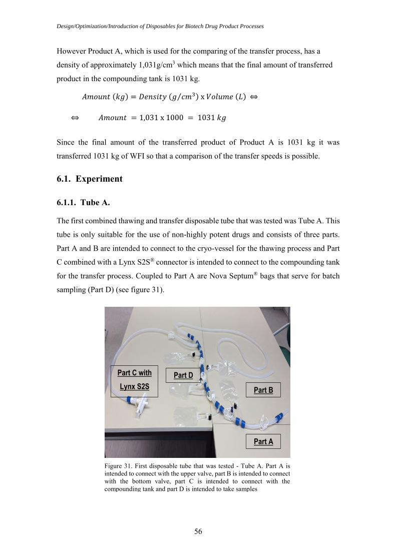
Design/Optimization/Introduction of Disposables for Biotech Drug Product Processes
56
However Product A, which is used for the comparing of the transfer process, has a
density of approximately 1,031g/cm3 which means that the final amount of transferred
product in the compounding tank is 1031 kg.
𝐴𝑚𝑜𝑢𝑛𝑡 (𝑘𝑔) = 𝐷𝑒𝑛𝑠𝑖𝑡𝑦 (𝑔 𝑐𝑚3⁄ ) x 𝑉𝑜𝑙𝑢𝑚𝑒 (𝐿)
⇔
⇔ 𝐴𝑚𝑜𝑢𝑛𝑡 = 1,031 x 1000 = 1031 𝑘𝑔
Since the final amount of the transferred product of Product A is 1031 kg it was
transferred 1031 kg of WFI so that a comparison of the transfer speeds is possible.
6.1. Experiment
6.1.1. Tube A.
The first combined thawing and transfer disposable tube that was tested was Tube A. This
tube is only suitable for the use of non-highly potent drugs and consists of three parts.
Part A and B are intended to connect to the cryo-vessel for the thawing process and Part
C combined with a Lynx S2S® connector is intended to connect to the compounding tank
for the transfer process. Coupled to Part A are Nova Septum® bags that serve for batch
sampling (Part D) (see figure 31).
Part C
with Lynx
S2S
Part D
Figure 31. First disposable tube that was tested - Tube A. Part A is intended to connect with the upper valve, part B is intended to connect with the bottom valve, part C is intended to connect with the compounding tank and part D is intended to take samples
Part A
Part B
Part D Part C with
Lynx S2S

Materials and Methods
57
Tube A was connected to the cryo-vessel in a class D room and then transported to the
compounding room, class C room. Part A was connected to the upper valve of the cryo-
vessel with a metal clamp and part B was connected to the bottom valve of the cryo-vessel
also with a metal clamp.
Two methods were used as moving force for the transfer of the solution to the
compounding tank: peristaltic pump and overpressure.
Experiment with peristaltic pump:
Although Part C has a Lynx S2S® connector, the experiment wasn´t performed with it as
it was designed for another plant and didn´t fit for Module 1 processes. Therefore, the
operators cut the connector and connected a short tube with a tri-clamp connection to the
existing tube. In the compounding room the transfer tube (Part C) was connected to the
compounding tank passing through a peristaltic pump with a tube connection piece. For
the transfer process approximately 200 rpm were used.
Figure 32. US Cryo-vessel with Tube A in class D room
(a) (b)
Figure 33. Part C of tube A with Lynx S2S® connector and with a tube connection piece (a) and Part C of Tube A after removing the Lynx S2S® connector and with a tube connection piece (b)
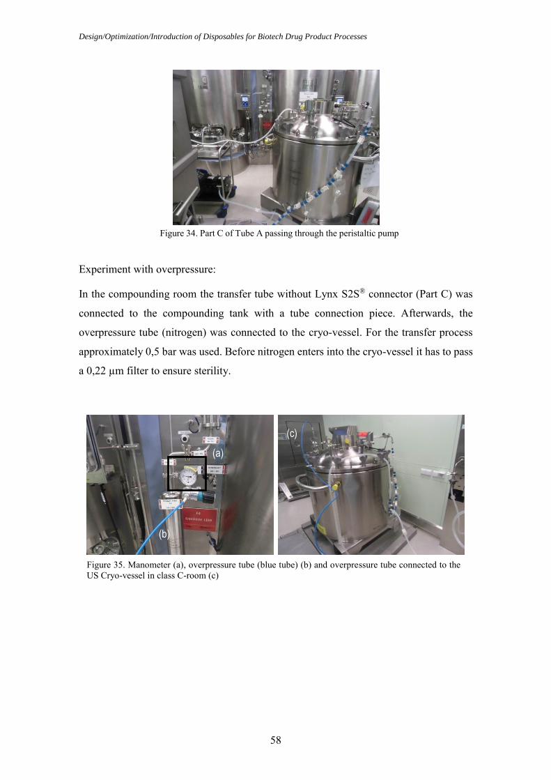
Design/Optimization/Introduction of Disposables for Biotech Drug Product Processes
58
Experiment with overpressure:
In the compounding room the transfer tube without Lynx S2S® connector (Part C) was
connected to the compounding tank with a tube connection piece. Afterwards, the
overpressure tube (nitrogen) was connected to the cryo-vessel. For the transfer process
approximately 0,5 bar was used. Before nitrogen enters into the cryo-vessel it has to pass
a 0,22 µm filter to ensure sterility.
Figure 34. Part C of Tube A passing through the peristaltic pump
(a)
(b)
(c)
Figure 35. Manometer (a), overpressure tube (blue tube) (b) and overpressure tube connected to the US Cryo-vessel in class C-room (c)

Materials and Methods
59
Experiment design of Tube A with peristaltic pump and overpressure:
6.1.2. Tube B.
The second tube that was tested was Tube B. This tube is a delivery tube for the
connection of different cryo-vessels (y-connector). It can connect up to four different
cryo-vessels (Part B, C, D and E) and can be used for the handling of API solutions and
for highly potent drugs, ADCs. Part A is intended for the connection with the
compounding tank and Part F is intended for flushing in case of highly potent drugs,
ADCs manipulation allowing the cleaning of the tube. However, Tube B was tested as a
combined thawing and transfer disposable tube to test the silicon tube material (see figure
37).
Part C
Part D Part E
Part B
Part A
Part F
Figure 37. Second disposable tube that was tested - Tube B. Part A is intended to connect with the compounding tank, Part B, C, D, E are intended to connect with different cryo-vessels and part F is intended for flushing
Figure 36. Experiment design of Tube A (a) with peristaltic pump and (b) with overpressure
(a) (b)

Design/Optimization/Introduction of Disposables for Biotech Drug Product Processes
60
Tube B was connected to the cryo-vessel in a class D room and then transported to the
compounding room, class C room. Part A was connected to the upper valve with a tri-
clamp connection and part C was connected to the bottom valve of the cryo-vessel also
with a tri-clamp connection.
Two methods were used as moving force for the transfer of the solution to the
compounding tank: peristaltic pump and overpressure.
Experiment with peristaltic pump:
In the compounding room the transfer tube (Part E) was connected to the compounding
tank with a tri-clamp connection passing through a peristaltic pump. For the transfer
process approximately 200 rpm was used.
Figure 39. Part E of Tube B passing through the peristaltic pump
Figure 38. US Cryo-vessel with Tube B in class D room

Materials and Methods
61
Experiment with overpressure:
In the compounding room the transfer tube (Part E) was connected to the compounding
tank with a tri-clamp connection. Afterwards, the overpressure tube (nitrogen) was
connected to the cryo-vessel. For the transfer process approximately 0,5 bar was used.
Before nitrogen enters into the cryo-vessel it has to pass a 0,22 µm filter to assure sterility.
Experiment design of Tube B with peristaltic pump and overpressure:
Figure 40. Manometer (a) and overpressure tube (blue tube) (b) and overpressure tube connected to the US Cryo-vessel in class C-room (c)
(a)
(b)
(c)
Figure 41. Experiment design of Tube B (a) with peristaltic pump and (b) with overpressure
(a) (b)
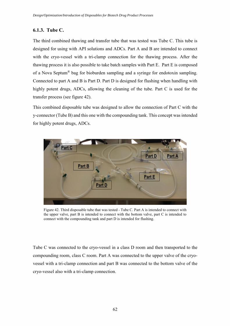
Design/Optimization/Introduction of Disposables for Biotech Drug Product Processes
62
6.1.3. Tube C.
The third combined thawing and transfer tube that was tested was Tube C. This tube is
designed for using with API solutions and ADCs. Part A and B are intended to connect
with the cryo-vessel with a tri-clamp connection for the thawing process. After the
thawing process it is also possible to take batch samples with Part E. Part E is composed
of a Nova Septum® bag for bioburden sampling and a syringe for endotoxin sampling.
Connected to part A and B is Part D. Part D is designed for flushing when handling with
highly potent drugs, ADCs, allowing the cleaning of the tube. Part C is used for the
transfer process (see figure 42).
This combined disposable tube was designed to allow the connection of Part C with the
y-connector (Tube B) and this one with the compounding tank. This concept was intended
for highly potent drugs, ADCs.
Tube C was connected to the cryo-vessel in a class D room and then transported to the
compounding room, class C room. Part A was connected to the upper valve of the cryo-
vessel with a tri-clamp connection and part B was connected to the bottom valve of the
cryo-vessel also with a tri-clamp connection.
Part B
Part C
Part D
Part E
Part C
Figure 42. Third disposable tube that was tested - Tube C. Part A is intended to connect with the upper valve, part B is intended to connect with the bottom valve, part C is intended to connect with the compounding tank and part D is intended for flushing.
Part A
Part D
Part D
Part B
Part E
Part C

Materials and Methods
63
Two methods were used as moving force for the transfer of the solution to the
compounding tank: peristaltic pump and overpressure.
Figure 44. Transfer concept for ADCs: connection of Tube C with y-connector and connection of y-connector with the compounding tank
Figure 43. US Cryo-vessel with Tube C in class D room (a) and US Cryo-vessel with Tube C connected to the y-connector in class D room (b)
(a) (b)
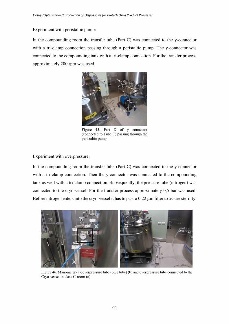
Design/Optimization/Introduction of Disposables for Biotech Drug Product Processes
64
Experiment with peristaltic pump:
In the compounding room the transfer tube (Part C) was connected to the y-connector
with a tri-clamp connection passing through a peristaltic pump. The y-connector was
connected to the compounding tank with a tri-clamp connection. For the transfer process
approximately 200 rpm was used.
Experiment with overpressure:
In the compounding room the transfer tube (Part C) was connected to the y-connector
with a tri-clamp connection. Then the y-connector was connected to the compounding
tank as well with a tri-clamp connection. Subsequently, the pressure tube (nitrogen) was
connected to the cryo-vessel. For the transfer process approximately 0,5 bar was used.
Before nitrogen enters into the cryo-vessel it has to pass a 0,22 µm filter to assure sterility.
Figure 46. Manometer (a), overpressure tube (blue tube) (b) and overpressure tube connected to the Cryo-vessel in class C-room (c)
(a)
(b)
(c)
Figure 45. Part D of y connector (connected to Tube C) passing through the peristaltic pump

Materials and Methods
65
Experiment design of Tube C with peristaltic pump and overpressure:
Figure 47. Experiment design of Tube C with (a) peristaltic pump and (b) overpressure
(a) (b)
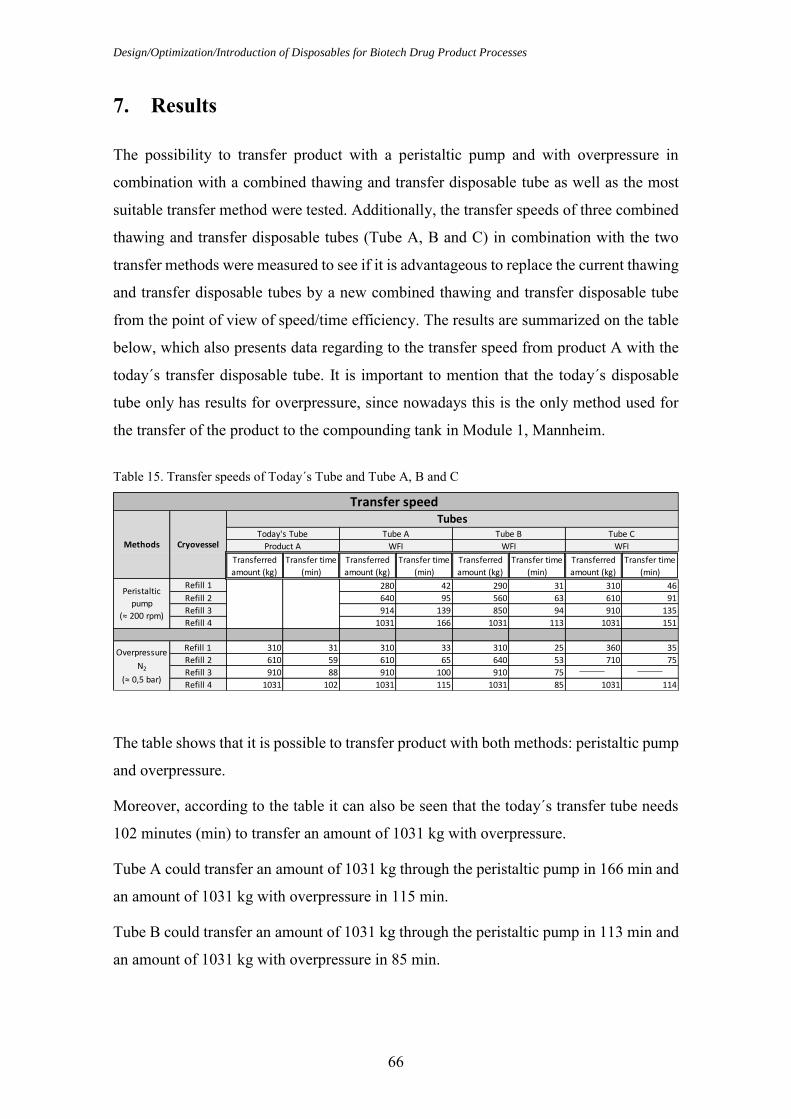
Design/Optimization/Introduction of Disposables for Biotech Drug Product Processes
66
7. Results
The possibility to transfer product with a peristaltic pump and with overpressure in
combination with a combined thawing and transfer disposable tube as well as the most
suitable transfer method were tested. Additionally, the transfer speeds of three combined
thawing and transfer disposable tubes (Tube A, B and C) in combination with the two
transfer methods were measured to see if it is advantageous to replace the current thawing
and transfer disposable tubes by a new combined thawing and transfer disposable tube
from the point of view of speed/time efficiency. The results are summarized on the table
below, which also presents data regarding to the transfer speed from product A with the
today´s transfer disposable tube. It is important to mention that the today´s disposable
tube only has results for overpressure, since nowadays this is the only method used for
the transfer of the product to the compounding tank in Module 1, Mannheim.
The table shows that it is possible to transfer product with both methods: peristaltic pump
and overpressure.
Moreover, according to the table it can also be seen that the today´s transfer tube needs
102 minutes (min) to transfer an amount of 1031 kg with overpressure.
Tube A could transfer an amount of 1031 kg through the peristaltic pump in 166 min and
an amount of 1031 kg with overpressure in 115 min.
Tube B could transfer an amount of 1031 kg through the peristaltic pump in 113 min and
an amount of 1031 kg with overpressure in 85 min.
Table 15. Transfer speeds of Today´s Tube and Tube A, B and C
Transferred
amount (kg)
Transfer time
(min)
Transferred
amount (kg)
Transfer time
(min)
Transferred
amount (kg)
Transfer time
(min)
Transferred
amount (kg)
Transfer time
(min)
Refill 1 280 42 290 31 310 46
Refill 2 640 95 560 63 610 91
Refill 3 914 139 850 94 910 135
Refill 4 1031 166 1031 113 1031 151
Refill 1 310 31 310 33 310 25 360 35
Refill 2 610 59 610 65 640 53 710 75
Refill 3 910 88 910 100 910 75
Refill 4 1031 102 1031 115 1031 85 1031 114
Transfer speed
Methods Cryovessel
TubesToday's Tube Tube A Tube B Tube C
Product A WFI WFI WFI
Peristaltic
pump
(≈ 200 rpm)
Overpressure
N2
(≈ 0,5 bar)

Results
67
At last, one can also observe that Tube C could transfer an amount of 1031 kg through
the peristaltic pump in 151 min and an amount of 1031 kg with overpressure in 114 min.
Consequently one can say that the transfer method with overpressure is faster than the
transfer method with peristaltic pump.
To summarize, Tube B reveals a better transfer speed with peristaltic pump and with
overpressure.
Based on the above results it is possible to design three graphs. The first one compares
the transfer speeds between the tubes with peristaltic pump, the second one compares the
transfer speeds with overpressure and the third one compares the transfer speeds between
the tubes with peristaltic pump and overpressure.
On the y axis the amounts of transferred product are expressed in kilograms, while on the
x axis the time of transfer is represented in minutes. The transfer speeds are represented
by plotted lines that combine the accumulated time (in minutes) and the transferred
amounts to accumulate 1031 kg of product.
Tube B reveals a better transfer speed with peristaltic pump.
Figure 48. Transfer speed of the tubes with peristaltic pump

Design/Optimization/Introduction of Disposables for Biotech Drug Product Processes
68
Tube B also reveals a better transfer speed with overpressure.
The transfer speed of the tubes using the overpressure method is in each single subgroup
higher than the one using the peristaltic pump method.
To see any possible statistical significance some statistical methods were used with
Microsoft Excel 2010 and Minitab® Software Version 16. Some statistical measures and
analysis are presented for a better understanding of the results. Aiming to enhance the
presentation of the results the following scheme will be considered (Brook, Q., 2010):
Figure 49. Transfer speed of the tubes with overpressure
Figure 50. Transfer speed of the tubes with peristaltic pump and overpressure
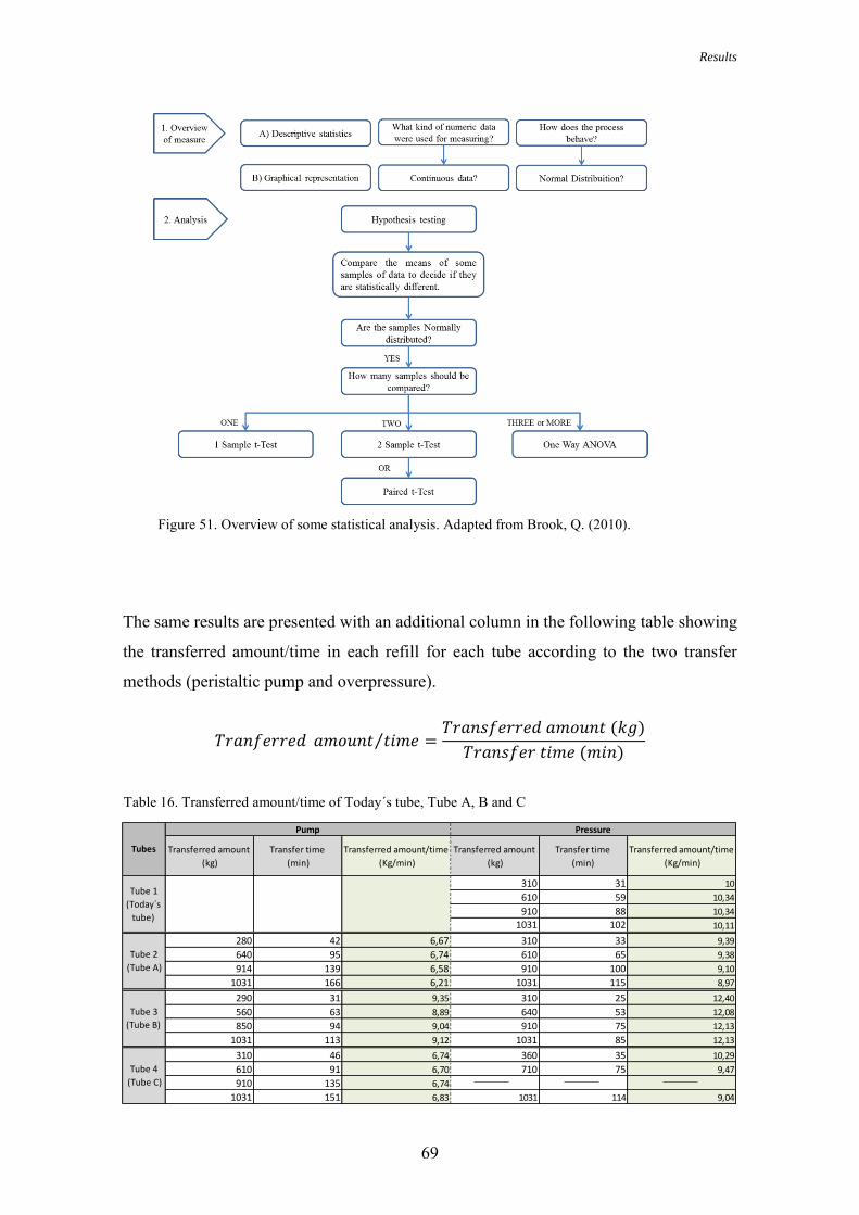
Results
69
The same results are presented with an additional column in the following table showing
the transferred amount/time in each refill for each tube according to the two transfer
methods (peristaltic pump and overpressure).
𝑇𝑟𝑎𝑛𝑓𝑒𝑟𝑟𝑒𝑑 𝑎𝑚𝑜𝑢𝑛𝑡 𝑡𝑖𝑚𝑒⁄ =𝑇𝑟𝑎𝑛𝑠𝑓𝑒𝑟𝑟𝑒𝑑 𝑎𝑚𝑜𝑢𝑛𝑡 (𝑘𝑔)
𝑇𝑟𝑎𝑛𝑠𝑓𝑒𝑟 𝑡𝑖𝑚𝑒 (𝑚𝑖𝑛)
Figure 51. Overview of some statistical analysis. Adapted from Brook, Q. (2010).
Table 16. Transferred amount/time of Today´s tube, Tube A, B and C
Transferred amount
(kg)
Transfer time
(min)
Transferred amount/time
(Kg/min)
Transferred amount
(kg)
Transfer time
(min)
Transferred amount/time
(Kg/min)
310 31 10
610 59 10,34
910 88 10,34
1031 102 10,11
280 42 6,67 310 33 9,39
640 95 6,74 610 65 9,38
914 139 6,58 910 100 9,10
1031 166 6,21 1031 115 8,97
290 31 9,35 310 25 12,40
560 63 8,89 640 53 12,08
850 94 9,04 910 75 12,13
1031 113 9,12 1031 85 12,13
310 46 6,74 360 35 10,29
610 91 6,70 710 75 9,47
910 135 6,74
1031 151 6,83 1031 114 9,04
Pressure
Tube 1
(Today´s
tube)
Tube 2
(Tube A)
Tube 3
(Tube B)
Tube 4
(Tube C)
Tubes
Pump
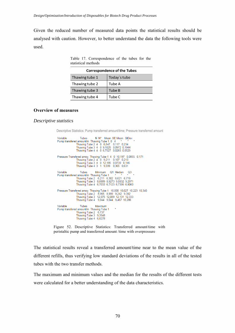
Design/Optimization/Introduction of Disposables for Biotech Drug Product Processes
70
Table 17. Correspondence of the tubes for the statistical methods
Given the reduced number of measured data points the statistical results should be
analysed with caution. However, to better understand the data the following tools were
used.
Overview of measures
Descriptive statistics
The statistical results reveal a transferred amount/time near to the mean value of the
different refills, thus verifying low standard deviations of the results in all of the tested
tubes with the two transfer methods.
The maximum and minimum values and the median for the results of the different tests
were calculated for a better understanding of the data characteristics.
Descriptive Statistics: Pump transferred amount/time; Pressure transferred amount
/time
Figure 52. Descriptive Statistics: Transferred amount/time with peristaltic pump and transferred amount /time with overpressure

Results
71
Graphical representation
The graph represents the transferred amount/time in the different refills for the tested
tubes according to the two transfer methods.
Numeric data used for measuring
The data obtained for the transfer amount/min are continuous data since they assume
values over the entire measured period and are clearly not limited to whole numbers. The
continuous data sometimes follow a normal distribution (Pedroso, A. C. & Gama, S. M.
A., 2004; Brook, Q., 2010).
Process behaviour
To evaluate the process behaviour of the data, a probability plot was constructed for the
today´s tube and the tested tubes (Tube A, B and C) with the two transfer methods
(peristaltic pump and overpressure).
The probability plot will help to answer if the data follow a normal distribution. If it is
the case they will fall in a straight line. However the line will never be perfectly straight
and that is the reason for a 95% CI (confidence interval) limits on the diagram. Then if
all points fall within the lines the data are normally distributed (Brook, Q., 2010).
Figure 53. Transferred amount/time of the tubes with peristaltic pump and overpressure

Design/Optimization/Introduction of Disposables for Biotech Drug Product Processes
72
As shown in the probability plot all data fall within the lines and moreover all p-values
are greater than 0,05. Consequently the data within each subgroup follow a normal
distribution.
Analysis One Way ANOVA
Since the data follow a normal distribution and the number of samples is more than three
a One Way ANOVA was performed to compare the means of the data samples and decide
if they are statistically different.
For the One Way ANOVA technique there are two hypothesis: the null hypothesis and
the alternative hypothesis. The null hypothesis tests that there is no difference in the
means of the transferred amount/time values across the four different tubes-subgroups
with peristaltic pump and overpressure. The alternative hypothesis tests that there is a
difference.
Two Interval plots were calculated to compare the transferred amount/time of the
different tubes with the two transfer methods. An interval plot is a graphical summary of
the distribution of the samples that shows the samples central tendency and variability.
Each dot represents a sample mean from a subgroup and each interval is a 95% CI for
that sample mean (Pedroso, A. C. & Gama, S. M. A., 2004; Brook, Q., 2010).
Probability Plot of Pump transferred amount/time; Pressure transferred amount/time
Normal – 95% CI
Figure 54. Probability plot of the transferred amount/time with peristaltic pump and overpressure

Results
73
This plot compares the transferred amount/time of Tube A, B and C with peristaltic pump.
The means seem to be different in the three tubes-subgroups but the difference between
Tube A (thawing tube 2) and C (thawing tube 4) is probably not significant because the
interval bars easily overlap. However, the difference between the means of Tube A
(thawing tube 2) and C (thawing tube 4) with Tube B (thawing tube 3) is probably
significant because the interval bars do not overlap.
This plot compares the transferred amount/time of Today´s tube, Tube A, B and C with
overpressure. The means seem to be different in the four tubes-subgroups but the
difference between Today´s tube (thawing tube 1) and Tube C (thawing tube 4) and the
difference between Tube A (thawing tube 2) and Tube C (thawing tube 4) are probably
not significant because the interval bars easily overlap. However, in this plot it can also
be seen that the difference between the means of Today´s tube (thawing tube 1), Tube A
(thawing tube2) and C (thawing tube 4) with Tube B (thawing tube 3) and the difference
Interval Plot of Pump transferred amount/time
95% CI for the mean
Figure 55. Interval plot for the transferred amount/time of the tubes with peristaltic pump
Interval Plot of Pressure transferred amount/time
95% CI for the mean
Figure 56. Interval plot for the transferred amount/time of the tubes with overpressure

Design/Optimization/Introduction of Disposables for Biotech Drug Product Processes
74
between Today´s tube (thawing tube 1) with Tube A (thawing tube 2) are probably
significant because the interval bars do not overlap.
Since the p-value is greater than 0,05 for every sample (see figure 54) the data are all
normally distributed. As represented in table 16 the number of samples is more than three
so a One Way ANOVA test will be performed to compare the averages of the data samples
to decide if they are statistically different.
The results of the ANOVA test can be presented in the ANOVA tables output (see figure
57 and 58).
The p-value on the ANOVA table output is the result for the hypothesis test. The p-value
is 0, 000 which demonstrates that there is a difference in the means of the transferred
amount/time values between the tubes-subgroups tested with the peristaltic pump method.
In the ANOVA table output a diagram of the samples means and their 95% CI is also
presented. Tube B (thawing tube 3) is the sample with the average value that is most
different from the others, so maybe the results of this tube have caused the p-value of the
whole test to be 0,000. Consequently the null hypothesis should be rejected.
Figure 57. One Way ANOVA table output for the transferred amount/time using peristaltic pump
One-way ANOVA: Pump transferred amount/time vs Tubes

Results
75
In this case the p-value is also 0, 000, which demonstrates that there is a difference in the
means of the transferred amount/time values between the tubes tested with the
overpressure method.
In the ANOVA table output it can be seen that Tube B (thawing tube 3) is again the
sample with the average value most different from the others, so maybe the results of this
tube have caused the p-value of the whole test to be 0,000. Consequently the null
hypothesis should be rejected.
Figure 58. One Way ANOVA table output for the transferred amount/time using overpressure
One-way ANOVA: Pressure transferred amount/time vs Tubes

Design/Optimization/Introduction of Disposables for Biotech Drug Product Processes
76
8. Discussion
In the present master thesis the possibility to transfer API solutions with a peristaltic pump
and with overpressure in combination with a combined thawing and transfer disposable
tube were tested, with the goal of finding the most suitable method. Moreover, the transfer
speed of three combined thawing and transfer disposable tubes was measured to decide
if it is advantageous to replace the current single thawing and single transfer disposable
tubes, taking also into account other additional factors.
The results demonstrate that is possible to transfer a solution with a peristaltic pump and
overpressure. On the one hand this was expected since the tubes that were tested are made
of silicone which is suitable for pumps. On the other hand the tubes and connectors didn´t
bust when overpressure was applied which means that the transfer process can also be
done with this kind of tubes and connectors applying an overpressure of around 0,5 bar.
The three tested combined thawing and transfer tubes reveal different results for the
transfer speed depending on their diameter and on the length of the transfer way. The
results demonstrate that tube B (thawing tube 3) has a faster transfer speed in both
methods used. Additionally the ANOVA tests showed a statistical difference in relation
to the other tubes. Considering that the flow of what was transferred corresponds to a
laminar flow then it is possible to use the Poiseuille’s equation (it was not calculated if
the flow was laminar or turbulent as this is not one of the targets of this master thesis):
𝑄 =∆𝑃 ∙ 𝜋 ∙ 𝑅4
8 ∙ 𝜂 ∙ 𝐿
where
𝑄 is the volumetric flow;
ΔP is the pressure difference between the two ends;
R is the radius;
η is the viscosity and
L is the length of the tube.
According to the Poiseuille’s equation, one can say that if the pressure difference, the
viscosity and the length of the tube are constant, then the transfer speed is proportional to

Discussion
77
the diameter. Additionally if the pressure difference, the viscosity and the diameter are
constant, then the transfer speed is inversely proportional to the length of the tube. Since
the radius is the fourth potency in relation to the length one can say that the radius has
more influence on the transfer speed as the length. Although tube B does not have the
shortest length, it was the tube with the fastest transfer speed since it has a wider diameter
than the other tubes and it is also why the ANOVA test showed a statistical difference of
tube B in relation to the other tubes.
8.1. Advantages of a combined thawing and transfer tube
The advantages of replacing the current single thawing and single transfer disposable
tubes by a combined thawing and transfer disposable tube are: there is no need for the use
of two different disposable tubes, the single thawing and single transfer disposable tubes
are combined in one disposable tube. Furthermore, there is a reduction on the quality risks
since the manual handling of the adapter is no longer required and therefore the process
is from the microbiological point of view more secure. Another advantage is the reduced
assembling time as the removal of the transfer tube, the assembly of the adapter and of
the transfer disposable tube are no longer needed (see figure 59). Moreover, if a combined
thawing and transfer disposable tube with the possibility for flushing is chosen, the safety
of ADCs will be improved.

Design/Optimization/Introduction of Disposables for Biotech Drug Product Processes
78
8.2. Disadvantages of a combined thawing and transfer tube
One of the disadvantages of a combined thawing and transfer disposable tube is that the
more complex the disposable is, the more expensive it probably becomes. Moreover, it
needs probably also more qualifications and it is more difficult to find a second supplier.
Additionally, due to the complexity of the disposable the shelf life can be diminished.
Figure 59. Cryo-vessel process cycle in Roche Diagnostics GmbH, Mannheim with the application of a combined thawing and transfer disposable tube
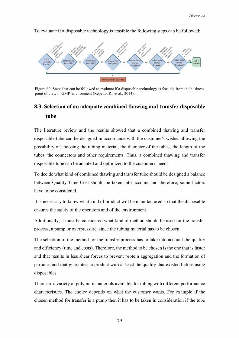
Discussion
79
To evaluate if a disposable technology is feasible the following steps can be followed:
8.3. Selection of an adequate combined thawing and transfer disposable
tube
The literature review and the results showed that a combined thawing and transfer
disposable tube can be designed in accordance with the customer's wishes allowing the
possibility of choosing the tubing material, the diameter of the tubes, the length of the
tubes, the connectors and other requirements. Thus, a combined thawing and transfer
disposable tube can be adapted and optimized to the customer's needs.
To decide what kind of combined thawing and transfer tube should be designed a balance
between Quality-Time-Cost should be taken into account and therefore, some factors
have to be considered.
It is necessary to know what kind of product will be manufactured so that the disposable
ensures the safety of the operators and of the environment.
Additionally, it must be considered what kind of method should be used for the transfer
process, a pump or overpressure, since the tubing material has to be chosen.
The selection of the method for the transfer process has to take into account the quality
and efficiency (time and costs). Therefore, the method to be chosen is the one that is faster
and that results in less shear forces to prevent protein aggregation and the formation of
particles and that guarantees a product with at least the quality that existed before using
disposables.
There are a variety of polymeric materials available for tubing with different performance
characteristics. The choice depends on what the customer wants. For example if the
chosen method for transfer is a pump then it has to be taken in consideration if the tube
Figure 60. Steps that can be followed to evaluate if a disposable technology is feasible from the business point of view in GMP-environment (Repetto, R., et al., 2014).

Design/Optimization/Introduction of Disposables for Biotech Drug Product Processes
80
has been tested and meets the needed standards and if it has an extended pump life. If the
chosen method for transfer is overpressure then it is important to choose a tube that has
been tested and meets the required standards and that can withstand the applied pressure.
According to the tested tubes a combination of different materials was also used with the
aim to achieve different performances.
However, the selected tubing materials should always be tested and qualified for
leachables and extractables in order to prevent product contamination and guarantee the
safety and quality of API solutions. Besides choosing the tubing materials, the diameter
and length have also to be determined. The tubing has to have an appropriate diameter
and length since it affects the transfer speed and therefore the efficiency. Moreover, the
diameter has to be chosen so that the tube fits in the peristaltic pump of the thawing station
and if the chosen method for the transfer process is a pump it has also to fit in the pump
of the compounding process. Furthermore, the tubing should have a suitable length so
that it can be connected to the thawing station and also from the cryo-vessel to the
compounding tank. Additionally, the length should also be suitable to prevent yield loss.
The connectors that are attached to the tubing in order to permit the different connections,
such as the connections to the cryo-vessel or to the compounding tank have to be chosen
in accordance with the facility and the level of sterility that must be assured. They should
protect the fluid path from microbiological contamination ensuring an aseptic process and
additionally ensure that there are no leaks that can lead to product loss. Moreover an
efficient connection should protect the operators and the surrounded environment.
Another aspect that has to be considered is that the connectors can burst with overpressure
compromising the fluid path. Therefore the choice of the connector and the applied
pressure has to be considered.
8.4. Recommendation of a transfer method
According to the literature some protein solutions that are shear-sensitive can be used
with peristaltic pumps (Niazi, S. K., 2012). However, because of peristaltic pumps some
tubing materials can release particles due to their poor abrasion resistance (Bahal, S. M.,
& Romansky, J. M., 2002; Colas, A., Malczewski, R., & Ulman, K., 2004). Moreover,
pumps like piston pumps and peristaltic pumps can cause protein aggregation and the
formation of protein particles due to shear forces (Wang, W., 1999; Bausch, U. J., 2008;
Maggio, E. T., 2008; Roche Internal Report, 2008; Nayak, A., Colandene, J., Bradford,

Discussion
81
V., & Perkins, M., 2011; Vázquez-Rey, M., & Lang, D. A., 2011; Ma, J. K., & Hadzija,
B., 2013).
Regarding the results of this master thesis it is better to use overpressure for the transfer
of product as it is faster (efficiency), as proved in the experiments and according to the
literature it minimizes the possibility of protein aggregation (quality) since only low to
moderate pressure is used (Chang, B. S., & Yeung, B., 2010; Wang, W., Nema, S., &
Teagarden, D., 2010; Meersman, F., Daniel, I., Bartlett, D. H., Winter, R., Hazael, R., &
McMillain, P. F., 2013). Furthermore, there are no changes in the transfer method, once
nowadays in Roche Mannheim, the transfer method that is used is overpressure.
Therefore, fewer mistakes would probably be made by the operators ensuring quality.
Nevertheless, obtaining stability data for each API solution that should be transferred is
always required to test this hypothesis. Consequently, using overpressure is considered
to be the best option for the transfer of product from the cryo-vessel to the compounding
tank.
8.5. Recommendation of a combined thawing and transfer disposable
tube
To decide what kind of combined thawing and transfer disposable tube is most suitable
to replace the current single thawing and single transfer tubes in Roche Diagnostic GmbH,
Mannheim some advantages and disadvantages of the tested tubes are presented in the
table below (see table 18).
Table 18. Advantages and disadvantages of the tested tubes

Design/Optimization/Introduction of Disposables for Biotech Drug Product Processes
82
According to the advantages and disadvantages presented in the table 18, although Tube
B showed the best results in terms of transfer speed it can´t be used alone as a combined
thawing and transfer disposable tube once it is a delivery tube for the connection of
different cryo-vessels. It can only be used in combination with a combined thawing and
transfer disposable tube. Therefore, Tube A is adequate to replace the current single
thawing and single transfer disposable tubes if it is used for non-hazardous API, since it
is not suitable for highly potent drugs. In addition it is already qualified. On the other
hand, tube C is adequate to replace the current single thawing and single transfer
disposable tubes as it has been specially designed for highly potent drugs and for Roche
Diagnostics GmbH, Mannheim. Regardless of the decision both tubes have to be
optimized in respect to the diameter and lengths.
8.6. Future research
Taking into consideration the time constraints and the master thesis deadline, only a
number of experiments were performed. Therefore, some additional tests and parameters
were not part of the evaluation process.
First, it was not possible to evaluate if a combined thawing and transfer disposable tube
is appropriate to all described types of cryo-vessels. Moreover, there is the need to see if
this concept can be used in all Modules of Roche Diagnostic GmbH, Mannheim.
Additionally, it must be tested if the combined thawing and transfer disposable tube is
adequate for the thawing process and how it will be transported in the cryo-vessel from
the API-group to the different Modules. Furthermore, only tube A is already qualified,
therefore, if the choice is to use tube C qualification and validation have to be done from
the start point of cGMP. At last, there are still GMP issues that have to be evaluated and
the need of a cost-benefit analysis.

Conclusion
83
9. Conclusion
In the pharmaceutical industry, concerns about quality, time and costs, make it necessary
for companies to analyse their processes and look for available technologies which allow
process optimization. There are different disposable technologies available in which
companies are investing due to their benefits.
In recent years, the pharmaceutical industry has developed new and more potent active
pharmaceutical ingredients. The development of innovative active pharmaceutical
ingredients, like antibody drug conjugates requires containment and appropriate
equipment and methods to ensure quality, efficiency and safety. With disposable
technologies it is possible to customize and therefore optimize the processes, handling
steps and yields.
As shown, the use of a combined thawing and transfer disposable tube makes it possible
to diminish the quality risks of manual handling, to reduce assembling time and improve
safety of antibody drug conjugates. Moreover, the transfer of active pharmaceutical
ingredient solutions is possible through the use of the two methods tested, peristaltic
pump and overpressure, whereas the overpressure transfer method proved to be faster and
has according to the literature research probably fewer effects on the stability of proteins.
Moreover, this is a transfer method that is already used in the described pharmaceutical
production area.
The decision of which combined thawing and transfer disposable tube should replace the
current single thawing and single transfer disposable tubes must be made by the
pharmaceutical company taking their needs into account. To conclude, the use of an
optimized combined thawing and transfer disposable tube in combination with the
overpressure transfer method would be an innovative process and would bring quality
and efficiency to a pharmaceutical sterile drug product manufacturing process.

Design/Optimization/Introduction of Disposables for Biotech Drug Product Processes
84
10. References
AdvantaPure (2012). APSH Braid-Reinforced Silicon Hose. Retrieved 25/09/2014,
from http://www.advantapure.com/apsh-silicone-hose.htm
AdvantaPure (2013). Ten Tips for Single Use Pharmaceutical Tubing Selection. The
American Pharmaceutical Review. Retrieved 02/10/2014, from
http://www.americanpharmaceuticalreview.com/1504-White-Papers-Application-
Notes/131624-Ten-Tips-for-Single-Use-Pharmaceutical-Tubing-Selection/
Aranha, H. (2004). Disposable systems. One More Manufacturing Option. BioProcess
International, 2(9), 6-16
Arnitz, T., & Liebig, C. (2011). U.S. Patent Application. Cryogenic container.
13/183,045. Retrieved 27/08/2014, from
http://www.google.com/patents/US20110309086
Atkinson, R. (1999). Project management: cost, time and quality, two best guesses and a
phenomenon, its time to accept other success criteria. International Journal of
Project Management, 17(6), 337-342. doi:10.1016/S0263-7863(98)00069-6
Avis, K. E. (Ed.). (1995). Sterile Pharmaceutical Products: Process Engineering
Applications (2nd ed., pp. 99-100). Retrieved 16/09/2014, from
http://books.google.de/books?id=Hy_X5NGEMqkC&printsec=frontcover&dq=St
erile+Pharmaceutical+Products:+Process+Engineering+Applications&hl=en&sa=
X&ei=fVZHVPH4JsLCOZecgLgG&redir_esc=y#v=onepage&q=Sterile%20Phar
maceutical%20Products%3A%20Process%20Engineering%20Applications&f=fal
se
Bahal, S. M., & Romansky, J. M. (2002). Spalling and Soprtion of Tubing for Peristaltic
Pumps. Pharmaceutical Development and Technology, 7(3), 317-323
Banga, A. K. (2005). Therapeutic peptides and proteins. Formulation, processing, and
delivery systems (2nd ed., p. 67). CRC Press Taylor & Francis. Retrieved
21/09/2014, from
http://books.google.de/books?id=rPFw2iPB51gC&printsec=frontcover&dq=Ther
apeutic+peptides+and+proteins:+formulation,+processing,+and+delivery+systems
+Therapeutic+peptides+and+proteins:+formulation,+processing,+and+delivery+s
ystems&hl=en&sa=X&ei=P1lHVNzLHMXXPInHgdAD&ved=0CCAQ6AEwAA

References
85
#v=onepage&q=Therapeutic%20peptides%20and%20proteins%3A%20formulati
on%2C%20processing%2C%20and%20delivery%20systems%20Therapeutic%20
peptides%20and%20proteins%3A%20formulation%2C%20processing%2C%20a
nd%20delivery%20systems&f=false
Bausch, U. J. (2008). Impact of filling processes on protein solutions (Doctoral
dissertation). University of Basel. Retrieved 01/10/2014, from
http://edoc.unibas.ch/845/1/DissB_8427.pdf
Belongia, B. M., & Allay, J. A. (2006). Characterization, Qualification, and Validation
of a Disposable Final Filling Process for Parenteral and Ophthalmic Drugs.
Pharmaceutical Technology, 30(3), 122-136
Boehm, J. (2010). Single-Use Connections Enable Advancements in Aseptic
Processing. BioProcess International, 8(4), 32-35
Bormett, D. (2008). High-potency APIs: containment and handling issues.
Pharmaceutical Technology, Supplement, s12-s16
Bowman, M. (2013). Developments in high potency API manufacturing. Speciality
Chemicals Magazine, p.30. Retrieved 18/08/2014, from
http://lifesciences.thomsonreuters.com/m/pdf/Bowman_SCM_Jul13.pdf
Brook, Q. (2010). Lean Six Sigma & Minitab.The Complete Toolbox Guide for all Lean
Six Sigma Practicioners (pp. 32-154). OPEX Resources Ltd
Calkins, T. (2010). Containment of High-Potency Products in a GMP
Environment. BioProcess International, 8(8), 14-18
Center for Chemical Process Safety (CCPS) (1993). Guidelines for Engineering Design
for Process Safety (104-105). American Institute of Chemical Engineers.
Retrieved 21/09/2014, from
http://books.google.de/books?id=mDgJjpmj950C&pg=PA105&dq=liquid+produc
t+transfer+-
+pressurizing+nitrogen+and+pump+guidelines&hl=en&sa=X&ei=Z6hHVJqiDc6
7PdeggIgO&ved=0CDsQ6AEwAg#v=onepage&q=liquid%20product%20transfer
%20-%20pressurizing%20nitrogen%20and%20pump%20guidelines&f=false
Code of Federal Regulations (CFR) Title 21, Part 211 (2014) - Equipment construction,
21CFR211.65. Retrieved 18/09/2014, from
Design/Optimization/Introduction of Disposables for Biotech Drug Product Processes
86
http://www.accessdata.fda.gov/scripts/cdrh/cfdocs/cfcfr/CFRSearch.cfm?CFRPart
=211&showFR=1&subpartNode=21:4.0.1.1.11.4
Challener, C. (2014). Appropriate Process Design Critical for Commercial Manufacture
of Highly Potent APIs. Pharmaceutical Technology, 38(4), 34-36
Chang, B. S., & Yeung, B. (2010). Physical stability of protein pharmaceuticals. In F.
Jameel & S. Hershenson (Eds.), Formulation and Process Development Strategies
for Manufacturing Biopharmaceuticals (2nd ed., pp. 89-92). John Wiley and Sons.
Retrieved 23/09/2014, from
http://books.google.de/books?hl=en&lr=&id=gNUltOoceOQC&oi=fnd&pg=PA6
9&dq=Physical+stability+of+protein+pharmaceuticals.&ots=upi5721uLo&sig=ev
NGELWFR4leD7ZyT-
_GXrJSHRA#v=onepage&q=Physical%20stability%20of%20protein%20pharma
ceuticals.&f=false
Colas, A. (2001). Silicone in Pharmaceutical Applications. Dow Corning. Retrieved
25/09/2014, from http://www.dowcorning.com/content/publishedlit/51-993a-
01.pdf
Colas, A., Malczewski, R., & Ulman, K. (2004). Silicone tubing for pharmaceutical
processing. Dow Corning. Retrieved 25/09/2014, from
http://www.dowcorning.com/content/publishedlit/52-1067-01.pdf
Creasey, J. & Thibon, V. (2013) Measuring Potential Leachables in Single-Use
Manufacturing Assemblies using Total Organic Carbon (TOC) Analysis.
American Pharmaceutical Review. Retrieved 14/08/2014, from:
http://www.americanpharmaceuticalreview.com/Featured-Articles/135984-
Measuring-Potential-Leachables-in-Single-Use-Manufacturing-Assemblies-using-
Total-Organic-Carbon-TOC-Analysis/
Day, N. (2004). GMP in pharmaceutical processing and its implications for centrifuges.
Filtration & separation, 41(2), 20-23. doi:10.1016/S0015-1882(04)00069-2
Denk, R. (2014). Herstellung von hochaktiven oder hochgefährlichen pharmazeutischen
Produkten. Die pharmazeutische Industrie, 76(5), 811-818
Desu, H. R., & Narishetty, S. T. (2013). Challenges in Freeze–Thaw Processing of Bulk
Protein Solutions. In P. Kolhe, M. Shah, & N. Rathore (Eds.), Sterile Product

References
87
Development. Formulation, Process, Quality and Regulatory Considerations (pp.
167-203). Springer New York. Retrieved 23/09/2014, from
http://download.springer.com/static/pdf/260/bok%253A978-1-4614-7978-
9.pdf?auth66=1413964552_a929d3f097eb0cd870e618330ad105c3&ext=.pdf.
doi:10.1007/978-1-4614-7978-9
Dow Corning (s.d). Tubing and Molded Assemblies Selection Chart. Retrieved
06/09/2014, from
http://www.dowcorning.com/content/publishedlit/Tubing_Chart.pdf?popup=true
Eibl, D., Peuker, T., & Eibl, R. (2011). Single-use equipment in biopharmaceutical
manufacture: a brief introduction. In R. Eibl & D. Eibl (Eds.), Single-use
technology in biopharmaceutical manufacture (pp. 3-11). John Wiley & Sons.
Retrieved 22/07/2014, from http://books.google.de/books?id=-
DYvRCfFG6sC&printsec=frontcover&dq=Single-
use+technology+in+biopharmaceutical+manufacture&hl=en&sa=X&ei=KmVHV
PKVEsT2OsiPgaAN&ved=0CDwQ6AEwAQ#v=onepage&q=Single-
use%20technology%20in%20biopharmaceutical%20manufacture&f=false
Farris, J. P., Ader, A. W., & Ku, R. H. (2006). History, implementation and evolution of
the pharmaceutical hazard categorization and control system. Chimica oggi, 24(2),
5-10
Garde, R. J. (1997). Fluid Mechanics through Problems (2nd ed., p. 526). New Age
International. Retrieved 16/09/2014, from
http://books.google.de/books?id=m1DOVKahg6EC&printsec=frontcover&dq=Fl
uid+Mechanics+through+problems&hl=en&sa=X&ei=o2lHVJizPMauPOrRgZA
D&ved=0CCIQ6AEwAA#v=onepage&q=Fluid%20Mechanics%20through%20pr
oblems&f=false
Greb, E. (2010). Are Disposables Components Powerful Enough to Manufacture Highly
Potent Drugs? Pharmaceutical Technology. Retrieved 19/09/2014, from
http://www.pharmtech.com/pharmtech/Production+Lines/Are-Disposable-
Components-Powerful-Enough-to-Manuf/ArticleStandard/Article/detail/682828
Gupta, A. K. & Arora, S. K. (2013). Industrial Automation and Robotics (2nd ed., pp.
32-34). University Science Press. Retrieved 16/09/2014, from
http://books.google.de/books?id=Y7rgCP7iC18C&pg=PA2&dq=Industrial+auto

Design/Optimization/Introduction of Disposables for Biotech Drug Product Processes
88
mation+and+robotics&hl=en&sa=X&ei=WGtHVOePLYjyOJ_LgfAN&ved=0CD
UQ6AEwAA#v=onepage&q=Industrial%20automation%20and%20robotics&f=f
alse
Harris, R. (2012). Formulating High Potency Drugs. Product development challenges.
Contract Pharma. Retrieved 18/08/2014, from
http://www.contractpharma.com/issues/2012-10/view_features/formulating-high-
potency-drugs/
Hunt, D. G. (2013). Plastic Packaging Materials and Systems for Drug Products. U.S.
Pharmacopeial Convention. Retrieved 25/09/2014, from
http://www.usp.org/sites/default/files/events/stakeholder_forums/2013/meeting-
5/04b-extractables-leachables-and-plastics-packaging-2014-03-07.pdf
Jenness, E., & Gupta, V. (2011). Implementing a Single-Use Solution for Fill–Finish
Manufacturing Operations. BioProcess International, 9(5), 22-25
Jornitz, M. W., Cappia, J.-M. & Meltzer, T. H. (2009). Disposable Components in
Aseptic Processing. Pharmaceutical Technology, Supplement, s10-s15
Jornitz, M. W., Szarafinski, D., & Peuker, T. (2012). Single-Use Technologie:
Opportunities in Biopharmaceutical Processes. In Subramanian, G. (Ed.),
Biopharmaceutical production technology (Volume 2, pp. 810-811). John Wiley
& Sons. Retrieved from http://books.google.de/books?id=NXl--
7u2PPQC&printsec=frontcover&dq=Biopharmaceutical+production+technology+
vol+2&hl=en&sa=X&ei=O61HVIHgKYWHPZjcgZgM&redir_esc=y#v=onepage
&q=Biopharmaceutical%20production%20technology%20vol%202&f=false
Jornitz, M. W., Szarafinski, D., & Peuker, T. (2012). Single-Use Technologie:
Opportunities in Biopharmaceutical Processes. In Subramanian, G. (Ed.),
Biopharmaceutical production technology (Volume 2, pp. 810-811). John Wiley
& Sons. Retrieved 22/07/2014, from http://books.google.de/books?id=NXl--
7u2PPQC&printsec=frontcover&dq=Biopharmaceutical+production+technology+
vol+2&hl=en&sa=X&ei=O61HVIHgKYWHPZjcgZgM&redir_esc=y#v=onepage
&q=Biopharmaceutical%20production%20technology%20vol%202&f=false
Kantor, A., Tchessalov, S., & Warne, N. (2011). Quality-by-Design for Freeze-Thaw of
Biologics: Concepts and Application to Bottles of Drug Substances. American
Pharmaceutical Review. Retrieved 27/08/2014, from

References
89
http://www.americanpharmaceuticalreview.com/Featured-Articles/36901-Quality-
by-Design-for-Freeze-Thaw-of-Biologics-Concepts-and-Application-to-Bottles-
of-Drug-Substance/
Kantor, A., MacMillan, S., Ho, K., Tchessalov, S., & Warne, N. (2011). Quality-by-
Design for Freeze-Thaw of Biologics: Concepts and Application During
Controlled Freeze and Thaw. American Pharmaceutical Review. Retrieved
27/08/2014, from http://www.americanpharmaceuticalreview.com/Featured-
Articles/36989-Quality-by-Design-for-Freeze-thaw-of-Biologics-Concepts-and-
Application-During-Controlled-Freeze-and-Thaw/
Karmarkar, A. B. (2012) High Potency is fastest growing segment. Ingredients South
Asia, 50-52. Retrieved 18/08/2014, from
http://www.academia.edu/1533858/High_potency_is_fastest_growing_segment
Kauffman, J. S. (2006). Identification and risk-assessment of extractables and
leachables. Pharmaceutical Technology, 30(2), s14-s22
Kerry, F. G. (2007). Industrial Gas Handbook. Gas separation and purification (p. 243)
CRC Press Taylor & Francis. Retrieved 21/09/2014, from
http://books.google.de/books?id=cXNmyTTGbRIC&printsec=frontcover&dq=Ind
ustrial+gas+handbook:+gas+separation+and+purification&hl=en&sa=X&ei=Qm5
HVJq6DYPEPPqOgKAP&ved=0CDAQ6AEwAA#v=onepage&q=Industrial%20
gas%20handbook%3A%20gas%20separation%20and%20purification&f=false
Kolhe, P., & Badkar, A. (2013). Freeze-Thaw of Portein Bulk Drug Substance. In
Annual Newsletter of American Association of Pharmaceutical Scientists (AAPS)
Sterile Product Focus Group (pp. 2-4). Retrieved 27/08/2014, from
http://www.aaps.org/uploadedFiles/Functional/AAPS_Focus_Group_Discussion_
Board/Sterile_Products_Focus_Group/SPFG%20Newsletter-April%202013.pdf
Kubischik, J. & Schaupp, M. (2011). Single-use Technology for Formulation and
Filling Application. In R. Eibl & D. Eibl (Eds.), Single-use technology in
biopharmaceutical manufacture (p. 106). John Wiley & Sons. Retrieved
16/09/2014, from http://books.google.de/books?id=-
DYvRCfFG6sC&printsec=frontcover&dq=Single-
use+technology+in+biopharmaceutical+manufacture&hl=en&sa=X&ei=5WdHV

Design/Optimization/Introduction of Disposables for Biotech Drug Product Processes
90
Ny9KY2HPczfgJAN&ved=0CDwQ6AEwAQ#v=onepage&q=Single-
use%20technology%20in%20biopharmaceutical%20manufacture&f=false
Lambert, P. (2008). Dispensing Biopharmaceuticals with Piston and Peristaltic Pumps.
Pharmaceutical Technology. Retrieved 24/10/2014, from
http://www.pharmtech.com/pharmtech/Dispensing-Biopharmaceuticals-with-
Piston-and-Peri/ArticleStandard/Article/detail/550135
Legrand, B. (2004). Q-course Quality & Organization (1st ed., p. 8). Retrieved
08/10/2014, from
http://books.google.de/books?id=PV0P2MEjhZEC&printsec=frontcover&dq=Q-
course+Quality+%26+Organization&hl=en&sa=X&ei=4m9HVIarLYrsO-
yEgJAD&ved=0CCsQ6AEwAA#v=onepage&q=Q-
course%20Quality%20%26%20Organization&f=false
Lipták, B. G. (Ed.) (2003). Instrument Engineers' Handbook. Process Measurement and
Analysis (4th ed., pp. 252-253). CRC press Taylor & Francis. Retrieved
16/09/2014, from
http://books.google.de/books?id=a05NAvaqfcUC&printsec=frontcover&dq=Instr
ument+Engineers%27+Handbook&hl=en&sa=X&ei=oXFHVJPjG4eCPbqEgPA
H&ved=0CCIQ6AEwAA#v=onepage&q=Instrument%20Engineers'%20Handboo
k&f=false
Lonza (2012). Antibody Drug Conjugates. The next generation. Retrieved 20/08/2014,
from
http://bio.lonza.com/uploads/tx_mwaxmarketingmaterial/Lonza_Brochures_Antib
ody_Drug_Conjugates.pdf
Ma, J. K., & Hadzija, B. (2013). Basic Physical Pharmacy (pp. 467-468). Jones &
Bartlett Learning. Retrieved 21/09/2014, from
http://books.google.de/books?id=NLabiVZSE7QC&printsec=frontcover&dq=basi
c+physical+pharmacy&hl=en&sa=X&ei=SHNHVMf2IoH3O-
rNgdAD&sqi=2&ved=0CCAQ6AEwAA#v=onepage&q=basic%20physical%20p
harmacy&f=false
Mach, C. J., & Riedman, D. (2008). Reducing microbial contamination risk in
biotherapeutic manufacturing. BioProcess International, 6(8), 20-26

References
91
Maggio, E. T. (2008). Novel excipients prevent aggregation in manufacturing and
formulation of protein and peptide therapeutics. BioProcess International, 6(10),
58-65
Mari, G., Moccaldi, A., & Ludovisi, G., (2005). Handling of high potency drugs:
process and containment. WIT Press, 85, 257-266. doi:10.2495/EEH050281
Meersman, F., Daniel, I., Bartlett, D. H., Winter, R., Hazael, R., & McMillain, P. F.
(2013). High-pressure biochemistry and biophysics. Review Mineral
Geochemistry, 75, 607-648. doi:10.2138/rmg.2013.75.19
Mintz, C. (2009). Single-use, disposable products: a “state of the industry” update. Life
Science Leader. Retrieved 22/07/2014 from http://www.sartorius.de/fileadmin/fm-
dam/DDM/Bioprocess-
Solutions/Fluid_Management/General/Publications/State%20of%20Industry%20
Update%209-2-09.pdf
Mueller, D. (2014). Single-use systems in pharmaceutical applications – a GMP
inspectors view (not published). ECA Conference Single-Use Disposables,
Duesseldorf
Nayak, A., Colandene, J., Bradford, V., & Perkins, M. (2011). Characterization of
subvisible particle formation during the filling pump operation of a monoclonal
antibody solution. Journal of Pharmaceutical Sciences, 100(10), 4198-4204.
doi:10.1002/jps.22676
Niazi, S. K. (2012). Disposable Bioprocessing Systems (pp. 127-129). CRC press
Taylor & Francis. Retrieved 09/09/2014, from
http://books.google.de/books?id=U6ZUmkqFoYAC&printsec=frontcover&dq=Di
sposable+Bioprocessing+Systems&hl=en&sa=X&ei=bHVHVMDcIsjKPd6JgNg
H&ved=0CCIQ6AEwAA#v=onepage&q=Disposable%20Bioprocessing%20Syst
ems&f=false
Repetto, R., Munk, M., Brown, S., Carter, J., Guldager, N., Julien, C., Low, D.,
Markovic, I., Martin, J., Prieb, P., Smalley, C. J., & Wong, R. (2014). Technical
Report No. 66. Application of Single-Use Systems in Pharmaceutical
Manufacturing (p. 6-27). Parenteral Drug Association. Retrieved 09/10/2014,
from http://www.pda.org/footer/press-resources/press-releases/press-release-
detail/pda-offers-help-in-applying-single-use-systems-to-bio-pharma-operations

Design/Optimization/Introduction of Disposables for Biotech Drug Product Processes
92
Pedroso, A. C. & Gama, S. M. A. (2004). Introdução Computacional à Probabilidade e
Estatística (pp. 144-525). Porto Editora
Pora, H., & Rawlings, B. (2009). Managing solid waste from single-use systems in
biopharmaceutical manufacturing. BioProcess International, 7(1), 18-25
Rao, G., Moreira, A., & Brorson, K. (2009). Disposable bioprocessing: the future has
arrived. Biotechnology and bioengineering, 102(2), 348-356
Rawlings, B., & Pora, H. (2009). Environmental impact of single-use and reusable
bioprocess systems. BioProcess International, 7(2), 18-26
Roche Internal Document (2010)
Roche Internal Report (2008)
Rothe, S. & Eibl D. (2011). Systems for Coupling and Sampling. In R. Eibl & D. Eibl
(Eds.), Single-use technology in biopharmaceutical manufacture (pp. 53-66). John
Wiley & Sons. Retrieved 09/09/2014, from
http://books.google.de/books?id=vO57HWijFOoC&pg=PT48&dq=Single-
use+technology+in+biopharmaceutical+manufacture:+a+brief+introduction&hl=e
n&sa=X&ei=indHVMPTI8S7PdaKgUA&ved=0CDUQ6AEwAA#v=onepage&q
=Single-
use%20technology%20in%20biopharmaceutical%20manufacture%3A%20a%20b
rief%20introduction&f=false
Sandle, T., & Saghee, M. R. (2011). Some considerations for the implementation of
disposable technology and single-use systems in biopharmaceuticals. Journal of
Commercial Biotechnology, 17(4), 319-329. doi:10.1057/jcb.2011.21
Saint-Gobain (2014). C-flex Biopharmaceutical Tubing. Retrieved 06/09/2014, from
http://www.biopharm.saint-gobain.com/en/Products.asp?ID=17
Shanks, R., & Kong, I. (2012). Thermoplastic Elastomers. In Prof. Adel El-Sonbati
(Ed.), Thermoplastic elastomers (p. 140). Intech. Retrieved 07/10/2014, from
http://www.intechopen.com/books/thermoplastic-elastomers. doi: 10.5772/36807
Shukla, A., Mostafa, S., Wilson, M., & Lange, D. (2012). Vertical integration of
disposables in biopharmaceutical drug substance manufacturing. BioProcess
International, 10(6), 34-47

References
93
Sinclair, A., & Monge, M. (2002). Quantitative economic evaluation of single use
disposables in bioprocessing. Pharmaceutical Engineering, 22(3), 20-34
Spontak, R. J., & Patel, N. P. (2000). Thermoplastic elastomers: fundamentals and
applications. Current opinion in colloid & interface science, 5(5-6), 333-340. doi:
10.1016/S1359-0294(00)00070-4
Srinivasan, K. M. (2008). Rotodynamic pumps (Centrifugal and Axial) (pp. 1-5). New
Age International. Retrieved 16/09/2014, from
https://de.scribd.com/doc/34309334/Rotodynamic-Pumps
Strahlendorf, K. A., & Harper, K. (2009). A Review of Sterile Connectors. BioPharm
International, Guide to Disposables, 28-35
Thomas, C. R., & Geer, D. (2010). Effects of shear on proteins in solution.
Biotechnology Letters, 33(3), 443-456. doi:10.1007/s10529-010-0469-4
Valle, C. (2009). Biotechnology drugs: Integrated single-use technologies for
biopharmaceuticals. Filtration & Separation, 46(6), 18-21. doi: 10.1016/S0015-
1882(09)70225-3
Van Arnum, P. (2009). Examining High-Potency API Manufacturing. Pharmaceutical
Technology, 33(7), 42-46
Vázquez‐Rey, M., & Lang, D. A. (2011). Aggregates in monoclonal antibody
manufacturing processes. Biotechnology and bioengineering, 108(7), 1494-1508.
doi 10.1002/bit.23155
Volk, M. (2014). Pump Characteristics and Applications (3rd ed., pp. 1-22). CRC Press
Taylor & Francis. Retrieved 16/09/2014, form
http://books.google.de/books?id=4cKnAAAAQBAJ&pg=PA491&dq=Pump+char
acteristics+and+applications&hl=en&sa=X&ei=XHtHVKfwA8KsPNingJAF&ve
d=0CCIQ6AEwAA#v=onepage&q=Pump%20characteristics%20and%20applicat
ions&f=false
Wang, W. (1999). Instability, stabilization, and formulation of liquid protein
pharmaceuticals. International Journal of Pharmaceutics, 185(2), 129-188. doi:
10.1016/S0378-5173(99)00152-0
Design/Optimization/Introduction of Disposables for Biotech Drug Product Processes
94
Wang, W., Nema, S., & Teagarden, D. (2010). Protein aggregation—Pathways and
influencing factors. International Journal of Pharmaceutics, 390(2), 89-99. doi:
10.1016/j.ijpharm.2010.02.025
Webb, S. D., Webb, J. N., Hughes, T. G., Sesin, D. F., & Kincaid, A. C. (2002).
Freezing bulk-scale biopharmaceuticals using common techniques: and the
magnitude of freeze-concentration. Biopharm, 15(5), 22-34
Whitford, W. G. (2010). Single-use systems as principal components in bioproduction.
BioProcess International, 8(11), 34-42
Whitford, W. G. (2014). Single-Use and Sustainability. BioProcess International,
12(4)s, 12-17
Wollowitz, S. (2010). Managing high‐potency active pharmaceutical ingredients—A
drug sponsor's guide. Drug Development Research, 71(7), 420-428. doi:
10.1002/ddr.20385
Wong, R. (2004). Disposable assemblies in biopharmaceutical production. BioProcess
International, 2(9), 36-38
Wooge, C. (2014). Process Challenges of Antibody-Drug Conjugates. BioProcess
International, 12(6)s, 28-31
