wear of stamping tool without lubricant - estudo geral of... · ocorrência de uma falha da...
TRANSCRIPT

DEPARTAMENTO DE
ENGENHARIA MECÂNICA
Wear of stamping tool without lubricant
Submitted in Partial Fulfilment of the Requirements for the Degree of Master in
Materials Engineering
Author
Ivana Malnar
Advisors
Bruno Trindade
Marta Oliveira
Jury
President Professor Doutor Albano Cavaleiro
Professor Catedrático da Universidade de Coimbra
Vowels
Professor Doutor Mitjan Kalin
Full Professor at University of Ljubljana
Doutor Evaristo Peralta Investigador na Universidade de Coimbra
Advisor Professora Doutora Marta Oliveira
Professora Auxiliar da Universidade de Coimbra
In the framework of Joint European Master in tribology of Surfaces and Interfaces
Coimbra, July, 2015
ii
Acknowledgments
This research work was sponsored by national funds from the Portuguese Foundation for
Science and Technology (FCT) via the projects PTDC/EMS-TEC/1805/2012 and PEst-
C/EME/UI0285/2013 and by FEDER funds through the program COMPETE – Programa
Operacional Factores de Competitividade, under the project CENTRO -07-0224 -FEDER -
002001 (MT4MOBI).

iii
Abstract
The need to reduce the cost of a product in order to lower the price of it or increase the profits
is present in all industries. This became a necessity in order to stay competitive on the market.
The way this trend presented itself in the manufacturing industry is by affecting the steps
involved in the manufacturing process, meaning that the number of operations required to
produce a certain part is constantly reducing, while the complexity of each step is increasing.
The reduced number of tools, therefore, becomes more demanding in terms of dimensional
accuracy. This leads to serious consequences that consume both time and resources, if a fail in
the process occurs. Designing a highly reliable tool then becomes one of the key points in
creating an efficient process.
A highly reliable tool means that it undergoes little wear and deformation during its use.
Additionally for processes like worm forming, these requirements need to be kept even at
elevated temperatures. Thus studies have been made on self-lubricating coatings that would
provide protection against wear and increase tools life span as well as reduce the need for
liquid toxic lubricants that have been used so far.
DLC-Si and W-Ti-N coatings, which show such properties, have been produced on pins and
disks of 100Cr6 steel and tested at room temperature, 100°C and 200°C using pin-on-disk
test. Tests were performed in dry conditions. The results obtained from coated and uncoated
steel parts were compared. Both pins and disks have been coated and tested against
aluminium alloy AA6016. Transfer layer of aluminium alloy was present on coated pins while
the layer was not found for coated disks. DLC-Si coated disks have shown lower coefficients
of friction and wear rates when compared to 100Cr6 steel for all temperature conditions. At
200°C W-Ti-N showed better or similar results to 100Cr6 and higher coefficients of friction
and wear rates at lower temperatures.
iv
Resumo
A necessidade de reduzir o custo de um produto, de forma a reduzir o seu preço final ou
aumentar o lucro, está presente em todos os setores industriais e é fundamental para que as
indústrias se mantenham competitivas. Tal envolve a redução do número de etapas
necessárias para o fabrico de um componente. No entanto, esta redução tem implicado um
aumento da complexidade de cada etapa do processo. Para além disso, a redução do número
de ferramentas envolvidas nos processos produtivos exigente maior controlo dimensional. A
ocorrência de uma falha da ferramenta, durante o processo de fabrico de um componente,
provoca graves consequências, com consumo adicional de tempo e recursos. O projeto
adequado de uma ferramenta fiável é, assim, um dos pontos-chave na criação de um processo
produtivo eficiente.
Uma ferramenta confiável apresenta níveis de desgaste e deformação reduzidos durante a seu
tempo de vida. Tal é ainda mais premente no caso de processos de conformação a média e alta
temperatura. Os revestimentos auto-lubrificantes podem ser uma mais-valia para as
ferramentas, já que contribuem para a redução do seu desgaste, com consequente aumento da
sua vida útil. Por outro lado, permitem a diminuição do nível de lubrificantes líquidos tóxicos
utilizados atualmente.
Nesta dissertação foram estudados dois revestimentos com composição química diferente
(DLC-Si e W-Ti-N), passíveis de serem utilizados como materiais auto-lubrificantes. A
resistência ao desgaste destes revestimentos foi testada à temperatura ambiente, 100 °C e 200
°C, através do ensaio pino-disco. Os pinos e os discos em aço 100Cr6 foram revestidos com
DLC-Si e W-Ti-N e testados contra uma liga de alumínio, AA6016. Os resultados mostraram
a existência de uma camada de transferência de alumínio à superfície dos pinos revestidos.
Tal não se verificou no caso dos discos revestidos. Os discos revestidos com DLC-Si
apresentaram coeficientes de atrito e taxas de desgaste menores, quando comparados com os
discos de aço 100Cr6 não revestidos, para todas as condições de temperatura testadas. O
revestimento W-Ti-N teve um comportamento semelhante ou ligeiramente melhor que o aço
100Cr6 a 200 °C, mas para temperaturas inferiores os valores de coeficiente de atrito e de
taxa de desgaste são mais elevados.
v
Table of Contents
List of figures ..................................................................................................................................... vi
List of tables ..................................................................................................................................... vii
Symbology and acronyms ................................................................................................................ viii
1 Introduction ...................................................................................................................................1
1.1 Scope and motivation ..........................................................................................................1
1.2 Objectives / Goals of thesis ..................................................................................................2
1.3 Thesis structure ...................................................................................................................3
2 State of the art ...............................................................................................................................4
2.1 Aluminium in industry ..........................................................................................................4
2.2 Hot and warm forming .........................................................................................................6
2.3 Warm forming of aluminium ................................................................................................7
2.4 Use of coatings................................................................................................................... 10
2.4.1 W-Ti-N coatings .......................................................................................................... 12
2.4.2 DLC-Si ......................................................................................................................... 16
3 Experimental methodology .......................................................................................................... 20
3.1 Material and specimen ....................................................................................................... 20
3.2 Experimental techniques .................................................................................................... 20
3.2.1 Deposition .................................................................................................................. 20
3.2.2 Characterisation ......................................................................................................... 21
4 Results and discussion ................................................................................................................. 26
4.1 Chemical and mechanical analysis ...................................................................................... 26
4.2 Structure ............................................................................................................................ 27
4.3 Pin-on-disk ......................................................................................................................... 28
4.4 Profilometry ....................................................................................................................... 35
5 Conclusion and future work ......................................................................................................... 41
6 Bibliography ................................................................................................................................. 42

vi
List of figures
Figure 1 - Material share as percent of vehicle weight ........................................................................4
Figure 2 - Use of aluminium in automotive industries in past 40 years ................................................5
Figure 3 - Direct and indirect hot stamping .........................................................................................6
Figure 4 - Main deformation mechanisms for sheet forming processes at elevated temperatures ......8
Figure 5 - Forming process window for hot stamping of AA6082 ........................................................9
Figure 6 - Typical tooling failure mechanisms ................................................................................... 10
Figure 7 - Hardness-depth profile of plasma nitrided and hardened specimens ................................ 11
Figure 8 - Hardness of W–Ti –N coatings deposited on nitriding treated high and low alloy steels .... 12
Figure 9 - EDX Zn maps and the corresponding friction curve ........................................................... 13
Figure 10 - Wear and coefficient of friction of uncoated and W–Ti-(N) coated balls .......................... 14
Figure 11 - Wear and coefficient of friction Of W-Ti-N coating with and without ion gun .................. 15
Figure 12 - Effective hardness vs. applied load of annealed and not annealed films .......................... 17
Figure 13 - Coefficient of friction as a function of the number of rotations in the ball-on-disc .......... 18
Figure 14 - Friction and abrasive wear of Si-DLC vs. silicon content ................................................... 18
Figure 15 - Principle of wear and friction optimised Si-DLC based layer system ................................ 19
Figure 16 - DC reactive magnetron sputtering .................................................................................. 20
Figure 17 - Scanning Electron Microscope ......................................................................................... 21
Figure 18 - Nanoindentation setup .................................................................................................. 22
Figure 19 - X'Pert by Philips .............................................................................................................. 23
Figure 20 - Schematic diagram of typical pin-on-disk equipment ...................................................... 23
Figure 22 – Profilometer .................................................................................................................. 24
Figure 21 - Pin-on-disk apparatus with heating equipment ................................................................ 24
Figure 23 - XRD pattern for W-Ti-N coating ....................................................................................... 27
Figure 24 - XRD pattern for DLC-Si coating ........................................................................................ 28
Figure 25 - Coefficient of friction curves for W-Ti-N coated disks ....................................................... 28
Figure 27 - Al disk after tests at 200°C ............................................................................................... 29
Figure 26 - Coefficient of friction curves for W-Ti-N coated balls ....................................................... 29
Figure 28 - Micrograph of W-Ti-N coated balls and Al disks a)22°C, b)100°C, c)200°C ........................ 30
Figure 29 - Micrograph of Al balls and W-Ti-N coated disks a)22°C, b)100°C, c)200°C ........................ 31
Figure 30 - Coefficient of friction curves for DLC-SI coated disks ........................................................ 32
Figure 31 - Coefficient of friction curves for DLC-SI coated balls ........................................................ 32
Figure 32 - Micrograph of Al disks and DLC-Si coated balls a)22°C, b)100°C, c)200°C ......................... 33
Figure 33 - Micrograph of Al balls and DLC-Si coated disks a)22°C, b)100°C, c)200°C ......................... 33
Figure 34 - Coefficient of friction for coated and steel disks .............................................................. 34
Figure 35 - Coefficient of friction for coated and steel balls ............................................................... 34
Figure 36 - Wear rate of aluminium disks against coated and uncoated balls .................................... 37
Figure 37 - Wear rate of aluminium disks against coated and uncoated balls (area enlarged) ............ 37
Figure 38 - Wear rate of aluminium balls against coated and uncoated disks .................................... 39
Figure 39 - Wear rate of aluminium balls against coated and uncoated disks (area enlarged) ........... 40

vii
List of tables
Table 1 - Chemical composition W-Ti-N ............................................................................................. 26
Table 2 - Chemical composition DLC-Si .............................................................................................. 26
Table 3 - Profilometry and wear rate of wear track son Al disks (W-Ti-N balls)................................... 35
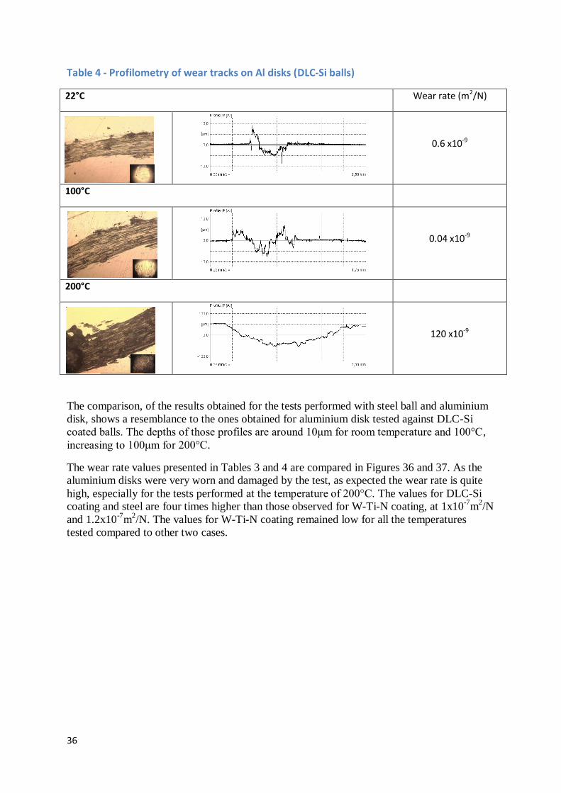
Table 4 - Profilometry of wear track son Al disks (DLC-Si balls) .......................................................... 36
Table 5 - Profilometry and wear rate - W-Ti-N disks .......................................................................... 38
Table 6 - Profilometry and wear rate - DLC-Si disks............................................................................ 39

viii
Symbology and acronyms
BPII - Plasma-Based Ion Implantation
d - Diameter (mm)
DLC - Diamond like carbon
EDS - Energy Dispersive Spectroscopy
F - Normal load (N)
GBS - Grain boundary sliding
H - Hardness
HMDSO - Hexamethyldisiloxane
k - Specific wear rate coefficient (m3/Nm or m
2/N)
Lc - Critical load
PECVD - Plasma-enhanced chemical vapour deposition
PLB - Power-Law Breakdown
PLC - Portevin–Le Chatelier effect
PVD - Physical Vapour Deposition
QPF - Quick plastic forming
s - Sliding distance (m)
SEM - Scanning Electron Microscope
SD - Solute drag creep
T - Temperature (°C)
t - Time (s)
TMS - Tetramethylsilane
V - Volume (m3)
XRD - X-Ray Diffraction Analysis
μ - Coefficient of friction
1
1 Introduction
1.1 Scope and motivation
The need to reduce cost of a product in order to decrease the final price or increase the profits
is present in all industries. This became a necessity in order to stay competitive on the market.
The way this trend presented itself in the manufacturing industry is by affecting the steps
involved in the process of manufacturing. More precisely, the number of operations required
to produce a certain part is constantly reducing, while the complexity of each step is
increasing.
The effect of price reduction influences the process parameters in order to reduce time
consumption. One of the most important parameters is coefficient of friction. To reduce its
effect different lubricants are applied in the process. Lubricants decrease friction by forming
lubricious oxides between the die and the sheet reducing wear and helping achieve smooth
material flow. Unfortunately lubricants in general are not environmentally friendly substances
and also add additional cost and production steps into process, as they need to be applied to
the sheet.
This is where the need for self-lubricating coatings arises from. Certain additions of elements
to coatings have shown lubricant like behaviour when used at warm or high temperatures.
Elements that have shown this type of behaviour have easy shearable planes, and are called
Magnéli oxide phases. The elements they are based on are V, Mo, Ti, Si, and W.
This study is testing two coatings that are expected to have such properties in the conditions
associated with warm forming process: W-Ti-N and DLC-Si. Their tribological properties
will therefore be tested through a range of temperatures starting from room temperature up to
200°C against an aluminium alloy - AA6061. Pin-on-disk equipment will be used for
simulation of sliding effect that occurs in deep drawing process.
2
1.2 Objectives / Goals of thesis
The main objective of this thesis is to conceive a comprehensive set of tests, which will
enable us to experimentally evaluate warm forming technological parameters of lightweight
advanced alloys. Obtaining reliable reference experimental data plays a key role for the whole
project of “Experimental and Numerical Simulation Analysis in the Optimisation of Warm
Forming of lightweight advanced sheet materials”, which is the framework for this study.
Therefore, it is intended to characterise materials at room and warm temperatures to be able to
cooperate with a team doing similar experiments on a testing stamping tool. This will in turn
enable the adaptation of accurate experimental conditions and procedures in order to produce
a fully documented and technically ascertained experimental and simulation results.
Following these objectives the results of this thesis will help to contribute to the knowledge
and development of simulation of the forming lightweight advanced alloys at room and warm
temperatures as well as describing the behaviour of these alloys during forming as function of
temperature and friction conditions.
The results of this study will also promote further research of the application of thin coatings
on die tools and contribute to understanding their behaviour during the forming process at
warm temperatures. In the greater picture contribute to improvement of production of
lightweight components using warm forming.

3
1.3 Thesis structure
This thesis is divided into five chapters. It begins with an introduction into the subject and
then continues to scope of objectives and motivation for this study.
The second chapter in divided into four sections and provides an overview of the present state
of the industry, especially of the warm and hot forming processes. Larger part of it covers
studies performed on thin film W-Ti-N and DLC-Si coatings and their application which will
be used for this study.
Chapter three explains in detail the methodology and equipment used for this study. The
techniques and methods used for interpreting the results obtained and the characterisation of
all tested materials.
Obtained results and discussion are presented in chapter four and finally conclusions and
future work recommendations are explained in chapter five.

4
2 State of the art
2.1 Aluminium in industry
In the past two decades the environmental awareness raised to the highest levels as the climate
changes and waste management become major issues in all parts of the world. Regulating
bodies have shown a serious concern for the environmental impact of industries, trying to
decrease it by imposing restrictions and directives that need to be followed [1]. Following
such regulations and their implementation means that companies need to adapt their processes
and ways of functioning, which requires financial investments and increases costs. This
means, that in order to keep customers and stay competitive on the market, cost needs to be
reduced in other parts of production process. However, the regulations also affect gas
consumption, emissions and the overall recyclability of a vehicle. This is where the use of
aluminium and magnesium alloys, and high strength steel started to rise and replace
traditional mild steel (Figure 1). Benefits of these materials, as shown by studies, are that
aluminium alloys for example reduce mass by 40-60% when compared to steel products,
same study with magnesium showed an even bigger reduction of 60-75%. However,
magnesium alloys present lower formability when compared to aluminium alloys at room
temperature. [2]
Figure 1 - Material share as percent of vehicle weight [3]
5
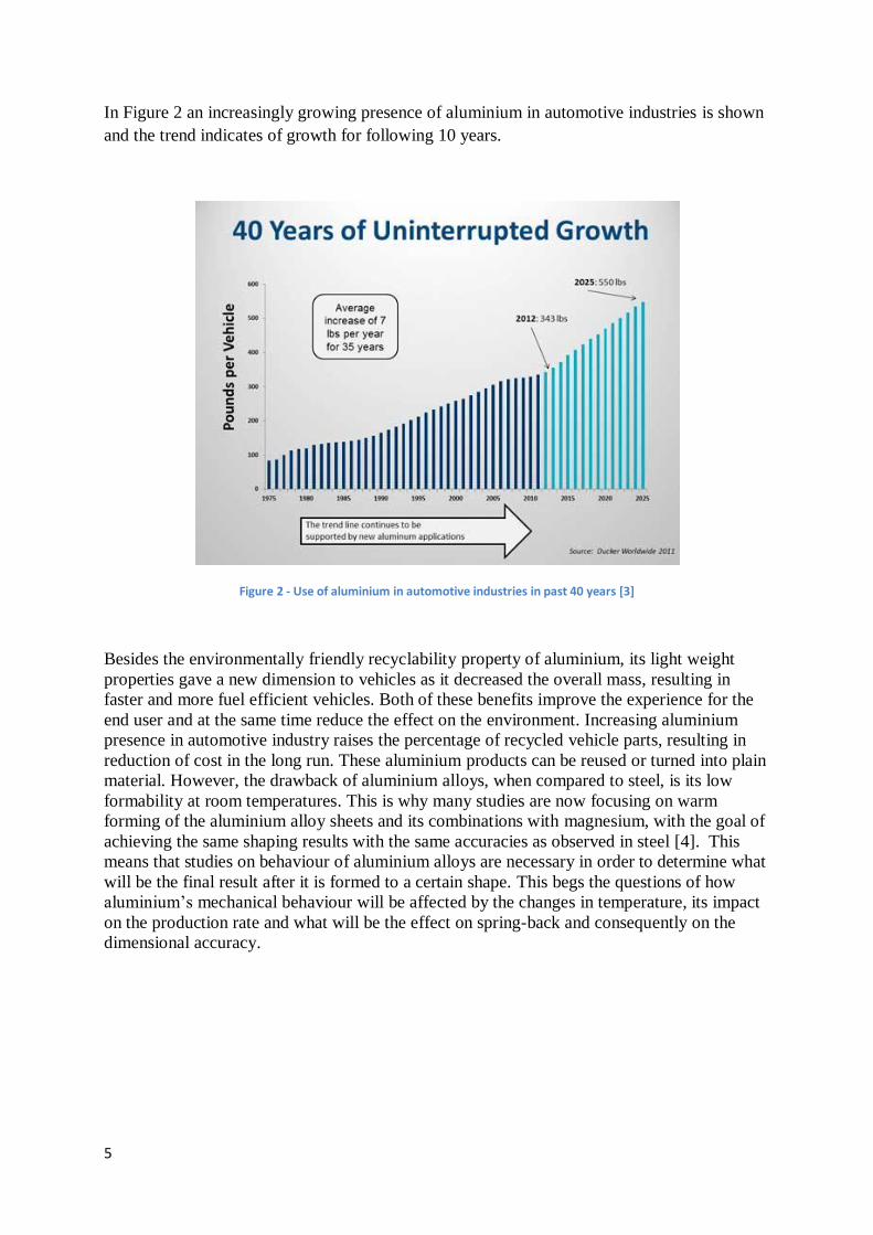
In Figure 2 an increasingly growing presence of aluminium in automotive industries is shown
and the trend indicates of growth for following 10 years.
Figure 2 - Use of aluminium in automotive industries in past 40 years [3]
Besides the environmentally friendly recyclability property of aluminium, its light weight
properties gave a new dimension to vehicles as it decreased the overall mass, resulting in
faster and more fuel efficient vehicles. Both of these benefits improve the experience for the
end user and at the same time reduce the effect on the environment. Increasing aluminium
presence in automotive industry raises the percentage of recycled vehicle parts, resulting in
reduction of cost in the long run. These aluminium products can be reused or turned into plain
material. However, the drawback of aluminium alloys, when compared to steel, is its low
formability at room temperatures. This is why many studies are now focusing on warm
forming of the aluminium alloy sheets and its combinations with magnesium, with the goal of
achieving the same shaping results with the same accuracies as observed in steel [4]. This
means that studies on behaviour of aluminium alloys are necessary in order to determine what
will be the final result after it is formed to a certain shape. This begs the questions of how
aluminium’s mechanical behaviour will be affected by the changes in temperature, its impact
on the production rate and what will be the effect on spring-back and consequently on the
dimensional accuracy.

6
2.2 Hot and warm forming
Hot stamping, also called press hardening, is a process where metallic sheets (blanks) are
heated to become malleable in order to be formed and rapidly cooled in special dies. Such
finished product has the final desired shape and material is hardened by the process. This is a
very effective combination of strength and dimensional complexity as it creates relatively
light-weight product. For comparison a different process such as cold stamping would require
more steps and possibly welding of bigger, heavier parts in order to achieve same
performance results. Therefore it is not a surprise that hot stamping is a very widely used
procedure in manufacturing industries. This is especially true for the automotive industry
where the parts produced are lightweight; improve crash performance and passenger safety
requirements. Hot stamping has an effect of increasing the tensile strength of material that is
being formed, because it is used for materials that undergo a phase transformation during the
cooling process. This wide use of hot stamping is also confirmed by statistical data, where the
number of hot stamped parts used in a vehicle has been increasing since year 2000, and in
2007 reached a value of approximately 107 million parts per year [5].
The hot stamping process is currently performed using two different methods: the direct and
the indirect hot stamping method, which are schematically shown in Figure 3.
Figure 3 - Direct and indirect hot stamping [6]
In the direct hot stamping process a furnace is used to heat up the material to desired
temperature. Material is then transferred to a press where it is formed and quenched in the
closed tool. The indirect hot stamping process involves an additional step, where the material
is nearly completely formed at room temperatures and then subjected to the quenching and
austenitization processes. Final calibration of the part is achieved in the press [7].
However, the hot forming technique is usually used for steel, which requires very high
temperatures in order to achieve the phase transformation. Therefore, warm forming was
developed as an alternative technique that could be used for softer materials such as
aluminium and magnesium alloys, but still offer the increase of formability and process
robustness. Warm forming is mostly used for its properties of increasing the material
formability and no spring-back effect. It usually involves dies that gradually deform a sheet of
metal into its final form, similar to hot forming, but at a temperature range of 100–350°C [8].

7
2.3 Warm forming of aluminium
The idea of vehicle mass reduction and the complexity of components that came as a result of
it, raised importance of aluminium alloys in the industry, especially of its formability
(ductility) as it is an important property for any material that is being plastically deformed.
Studies have been done on this subject in order to better understand behaviour of aluminium
alloys during a process like warm forming.
The mechanical behaviour of re-crystallized AA5182 sheet material was studied using tensile
tests, at temperatures ranging from 100°C up to 400°C, and strain rates from 10−3
up to 3 ×
10−2
s−1
. The forming conditions of quick plastic forming (QPF) were also tested and the
results indicate that three deformation regimes present:
1) deformation under solute drag creep, which gradually transitioned into power-law
breakdown
2) deformation under logarithmic creep
3) deformation under a transition into dynamic strain-aging, the PLC (the Portevin–Le
Chatelier) effect.
It was shown that strain-rate sensitivity controls tensile ductility during warm forming of the
AA5182 and that the effect of strain hardening on tensile ductility is negligible in the second,
logarithmic regime. In the third, PLC regime ductility showed to be at its lowest point; this
also disproved the importance of strain hardening to tensile ductility during warm forming,
which was given great importance by some theories. However, this type of quick plastic
forming has very low production rates, which makes it unsuited for a high-volume production
at a reasonable cost. If high production volumes and economic competitiveness is the aim of a
company, then hot stamping might be a more appropriate method as the absence of expensive
pre-treatments lowers material costs for the AA5xxx series [9].
Similarly to the study just described, other studies have been also conducted on different
aluminium alloys. The series that have been used throughout the studies are AA5xxx and
AA6xxx. These series represent the best candidates to replace steel used so far due to their
low density and good strength, very good corrosion resistance and the ability to be welded. In
addition, when compared to commonly used aluminium alloys for aeronautical applications,
AA5xxx and AA6xxx series proved to be more cost effective [10]. However, the drawbacks
of these materials come to light when they are formed at room temperature, since they exhibit
very low formability and do not provide accurate dimensions, which are caused by the
pronounced spring-back effect.
The effects of these two disadvantages were investigated. An improvement was found in a
study by Bariani et al. [10] where an aluminium alloy was subjected to plastic deformation at
elevated temperatures. In contrast to the solute drag creep (SD) which prevails in the QPF
method it was found that in hot stamping the deformation mechanism is the glide controlled
thermally activated dislocation mechanism. This type of mechanism is typical for a Power-
Law Breakdown (PLB). SPF, QPF and HS technologies and their corresponding deformation
mechanisms are shown on Figure 4. Thus hot stamping does not require a fine-grained alloy,
which means that the use of commercial grades is acceptable. Therefore AA5083 was used
and exhibited lowest ductility at the lowest strain rates, regardless of the testing temperature.
Also, an automotive component with a complex geometry was tested and confirmed that the

8
forming temperature of 450 °C can assure a geometrically sound component, with micro-
structural and mechanical characteristics comparable of those of the as-delivered blanks.
Figure 4 - Main deformation mechanisms for sheet forming processes at elevated temperatures [10]
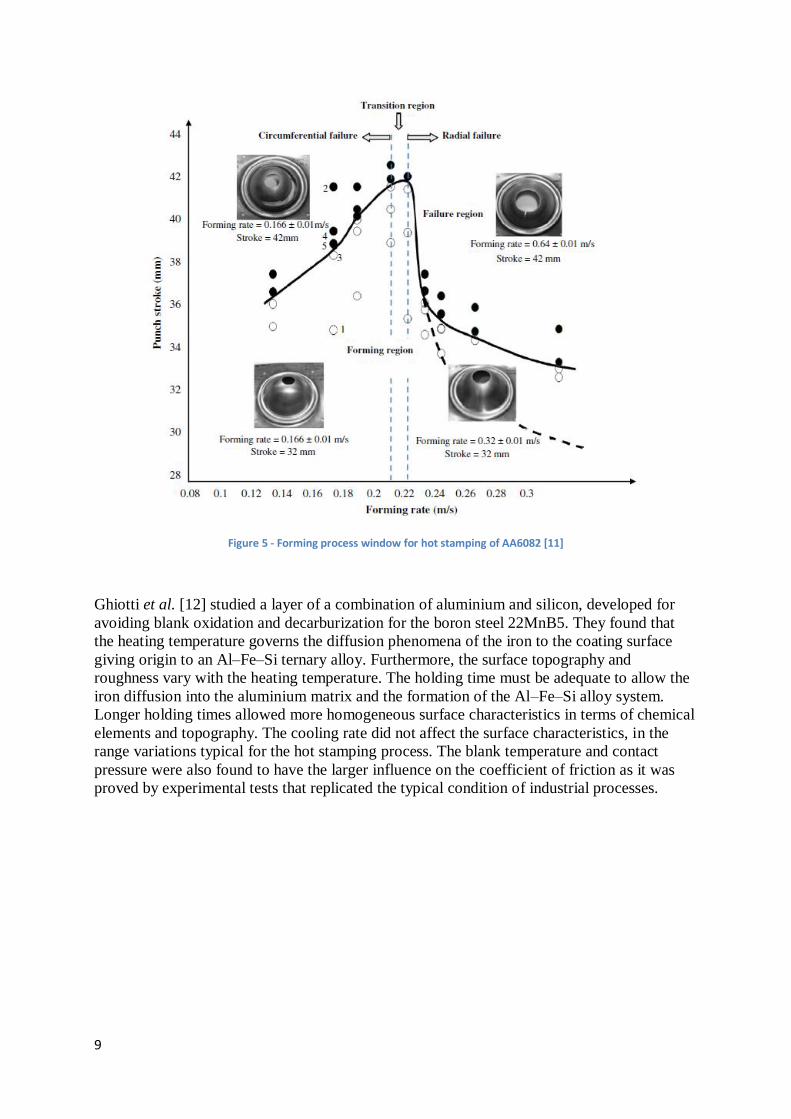
Study was performed in regard to the mechanical behaviour of an AA6082 aluminium alloy
considering hot stamping procedure. This study showed that failure features of panel parts are
dependent on the rate of forming. This is shown in a form of graph with matching pictures on
Figure 5. As can be seen from the graph in the case of a fast forming rate, failure mode was
shown to be radial tear emanating from the central hole on the formed cup (upper right
image). For a slow forming rate, the failure mode is a circumferential tear at a mid-height
location on the formed cup. The area marked by blue lines is where the largest drawing depth
and most uniform part thickness can be achieved i.e. with a forming rate of approximately
0.21 m/s. This study showed a very good combination of the use of alloy-specific material
models calibrated by matching experimental data to numerical, obtained using commercial FE
software. Limit curves obtained using this approach may save time and money which would
be otherwise spent on tests [11].
9
Figure 5 - Forming process window for hot stamping of AA6082 [11]
Ghiotti et al. [12] studied a layer of a combination of aluminium and silicon, developed for
avoiding blank oxidation and decarburization for the boron steel 22MnB5. They found that
the heating temperature governs the diffusion phenomena of the iron to the coating surface
giving origin to an Al–Fe–Si ternary alloy. Furthermore, the surface topography and
roughness vary with the heating temperature. The holding time must be adequate to allow the
iron diffusion into the aluminium matrix and the formation of the Al–Fe–Si alloy system.
Longer holding times allowed more homogeneous surface characteristics in terms of chemical
elements and topography. The cooling rate did not affect the surface characteristics, in the
range variations typical for the hot stamping process. The blank temperature and contact
pressure were also found to have the larger influence on the coefficient of friction as it was
proved by experimental tests that replicated the typical condition of industrial processes.

10
2.4 Use of coatings
In order to have a more cost effective process, dies used in forming have gained higher
geometrical complexity. This decreases time and fund requirements. In terms of forming
process itself, it increases the required dimensional accuracy of dies used in order to reduce
the number of steps involved. The tendency is also to decrease the additional processing, in
order to meet dimensional requirements after forming. Higher complexity of dies meet these
requirements, however, this also means an increase of possible wear, galling and deformation
of the dies, as shown on Figure 6. These defects in turn influence the accuracy of the formed
geometry in a greater manner, when compared to simple shapes.
Figure 6 - Typical tooling failure mechanisms [13]
This is where the use of lubricants comes into place. They are added to the process in order to
improve the contact conditions between the blank and the tools, enabling them to withstand
the severe conditions they can be exposed to during the long production cycles. However,
lubricants are not environmentally friendly, which presents a problem in terms of following
EU directives as they need to be properly managed during and after their use. Use of
lubricants also decreases production efficiency as cleaning operations of the products are
needed. Another problem arises when they are considered for warm or hot forming, since
lubricants typically experience behaviour of decreasing properties with increase of
temperature. In order for a tool to withstand wear, friction, oxidation and corrosion without
the use of lubricant, solid lubricants, coatings and their combinations in nanocrystalline or
multilayer structures are used. They increase the life span of tools and benefit their
performance. Yet when used in warm conditions their effectiveness decreases due to their low
resistance to oxidation.
Therefore, a new concept of lubrication has been designed, which is based on the formation of
lubricious oxides. These oxides are called Magnéli oxide phases and include elements such as
Ti, Si, Mo, W and V. They have easy shearable planes, which improve significantly the

11
lubrication efficiency and as a result protect the tool against wear and galling. Examples of
such coatings include Cu-Mo-S2, Cr-V-N, Ti-Si-V-N, Ti-Al-V-N, W-Ti-N, DLC-Si and many
more.
These coatings that are believed to form Magnéli oxide phases in contact have already been
used at room temperatures for sheet metal forming operations that require: (i) strict lubrication
conditions and geometrical accuracy and also for (ii) the stamping of ductile materials, such
as aluminium and titanium alloys, requiring very severe lubricant conditions to control the
galling problems. Benefits of using coatings were not only shown in large reductions of the
lubricant content, but also in the reduction of duration of production process time. Steps like
preparation and cleaning of the material were no longer necessary. The same tribological
behaviour for corrosion protection purposes has been achieved when using coatings with only
25% of the amount of the oil lubricant used without coatings involved [14, 15]. Therefore the
use of described coatings has potential to counterbalance the degradation of the oil lubrication
efficiency during the warm forming process.
However, thin films might not be enough to improve life span of a tool used in demanding
processes such as cutting and rolling. This is due to occurrence of elastic or plastic
deformation of the substrate which promotes deformation of the coating. In order to improve
these properties ion nitrating of substrate was introduced. This is a widely used process
because it incorporates the nitride atoms by diffusion into steel lattice, which in turn improves
fatigue strength, wear resistance and load bearing capacity properties [14]. The effect of
plasma nitriding is shown in Figure 7, where the clear rise in hardness is visible and behaviour
through 700μm in depth, shown. These excellent results were the source of the idea of using
such treated surfaces combined with hard coatings, in order to achieve very high wear
resistance. In this case the nitrided surface would prevent plastic deformation of substrate and
coating would add hardness to the material.
Figure 7 - Hardness-depth profile of plasma nitrided and hardened specimens [15]
12
2.4.1 W-Ti-N coatings
The idea of nitrated surface improving properties of a material, when combined with a thin
coating was tested using a TiN coating and a steel substrate. Several different combinations
were tested and the load bearing property was used for comparison. TiN coating on an un-
nitrated substrate had the lowest values of load bearing while the same coating had the highest
load bearing values on nitrated substrate. The load bearing properties were even better when
slight grinding was used to remove iron nitrate layer produced during plasma nitriding. This is
because of the formation of brittle and porous ‘‘white layer’’ of iron nitrides (ε-Fe2–3N or γ’-
Fe4N compound layer), which occurs at the top surface during nitriding. This combination had
highest wear resistance as well [14].
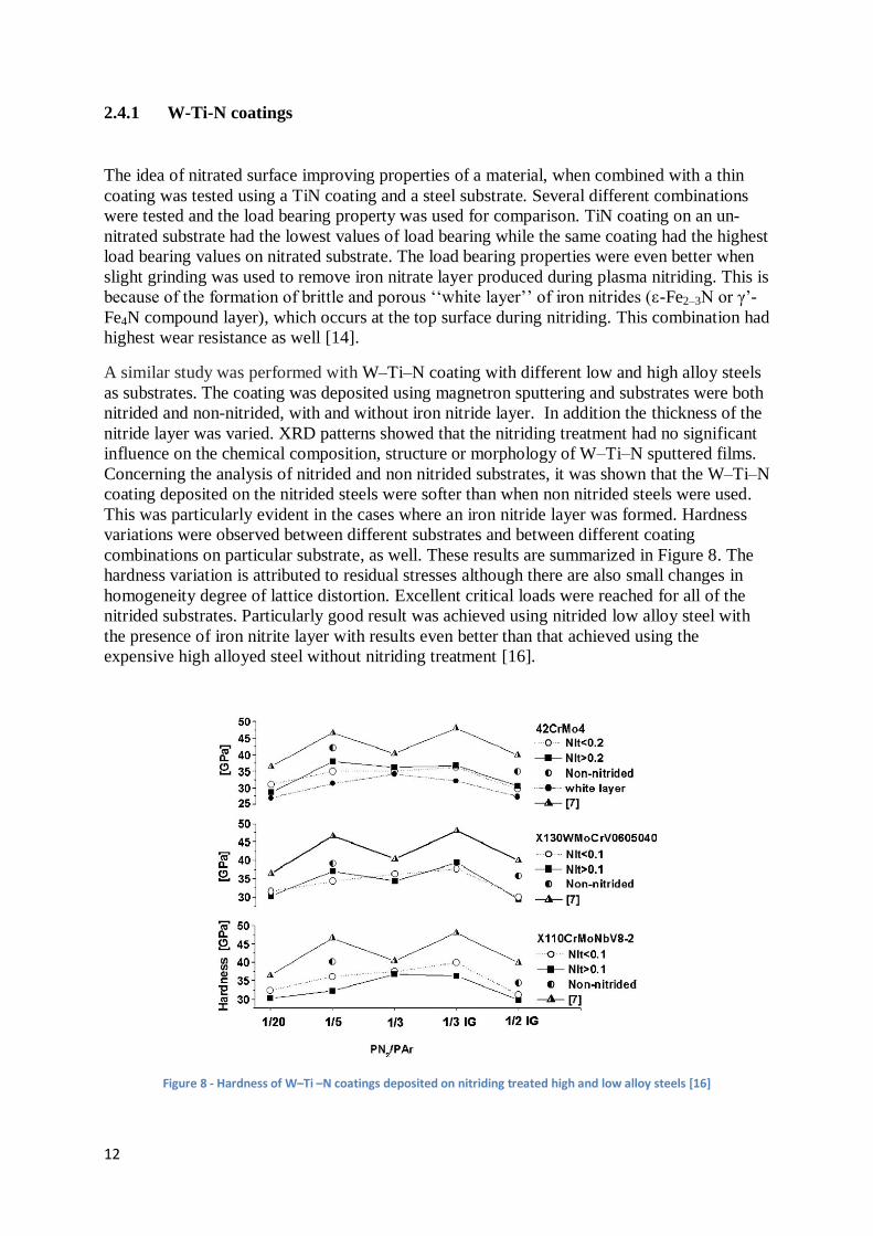
A similar study was performed with W–Ti–N coating with different low and high alloy steels
as substrates. The coating was deposited using magnetron sputtering and substrates were both
nitrided and non-nitrided, with and without iron nitride layer. In addition the thickness of the
nitride layer was varied. XRD patterns showed that the nitriding treatment had no significant
influence on the chemical composition, structure or morphology of W–Ti–N sputtered films.
Concerning the analysis of nitrided and non nitrided substrates, it was shown that the W–Ti–N
coating deposited on the nitrided steels were softer than when non nitrided steels were used.
This was particularly evident in the cases where an iron nitride layer was formed. Hardness
variations were observed between different substrates and between different coating
combinations on particular substrate, as well. These results are summarized in Figure 8. The
hardness variation is attributed to residual stresses although there are also small changes in
homogeneity degree of lattice distortion. Excellent critical loads were reached for all of the
nitrided substrates. Particularly good result was achieved using nitrided low alloy steel with
the presence of iron nitrite layer with results even better than that achieved using the
expensive high alloyed steel without nitriding treatment [16].
Figure 8 - Hardness of W–Ti –N coatings deposited on nitriding treated high and low alloy steels [16]

13
Beside the properties presented thus far, another important property of the contact pair
coating-material is the coefficient of friction. In this case the quality of the surface of both the
material and coating is of great importance. When a surface has impurities or defects,
problems with the adhesion of the coating to the substrate are very likely. Example of
adhesion problems are shown on Figure 9 through EDX Zn map. Map is showing the
increasing amount of Zn being adhered to a ball coated by DLC thin film. The tests were
performed for sliding contact and the coefficient of friction was also measured. After 50
cycles surface was mainly covered with ZnO. Frequently a consequence of adhesion is
formation of wear particles, which can damage surface by inducing scratches or promoting
abrasion. This in turn increases the coefficient of friction and makes contact more unstable.
This situation is very common for pairs of materials were one is hard and the other is soft and
ductile, such as aluminium and zinc. Reduction of coefficient of friction, wear and corrosion
has been studied through use of hard PVD coatings, such as nitrides, carbides or carbo-
nitrides of titanium, chromium or aluminium. These coatings showed an improvement in the
performance concerning all mentioned parameters. This in turn enables a better surface
finishing, extended life span and decreases the production and the maintenance costs [17].
Figure 9 - EDX Zn maps and the corresponding friction curve [17]
A study performed on the tribological characterisations of W-Ti-(N) coatings was using
conventional pin-on-disk equipment. The tests were done using coated and uncoated balls
against only uncoated sheets. This was done in order to address the issue of the evaluation of
wear resistance, which arises when coated disks are used, as a transfer layer is formed on the
disk, which protects the surface giving very low coefficient of friction. The transfer layer is
important as the tribological behaviour of the contact depends on it.
The contact conditions analysed in this study included both dry and lubricated tests, with
lubrication amounts being controlled and several different types of lubricants being tested.
The results showed that in dry conditions there was a high adhesion tendency for zinc layer
coated steel and aluminium alloy i.e. the soft sheet materials. This made a correct calculation
of the wear coefficients impossible to obtain. Similar tribological behaviour was found for all
uncoated and coated balls against HSLAS-F and DDS materials. Balls coated by W–Ti-N

14
(1/3) and W–Ti-N (1/5) showed the best tribological results. All of these tests, however,
showed high values of coefficient of friction ranging from 0.35 to 0.65 [18] as shown in
Figure 10.
Figure 10 - Wear and coefficient of friction of uncoated and W–Ti-(N) coated balls [18]
Lubricated tests lead to the conclusions that when compared to other types of lubricants, oil
had the biggest advantage. In this case amounts used to achieve desirable effect were as low
as 10% of the amount that is usually applied for this type of purposes and its value is around
0.2 g/m2. However, addition of lubrication did not help in terms of adhesion, which was
observed during tests on aluminium alloy sheets. Again the best results were achieved by
using W–Ti-N (1/5) coated ball; these results are explained by the highest value of hardness
of this sample. This sample also showed very good tribological results when tested with the
corrosion protection oil, this time the amounts of lubricant were only 25% of the total amount
usually utilized in the industry [18].
These studies show the improvements addition of nitrogen in a coating can make on the
tribological condition. This was also shown by another study where ion gun was used during
film growth in order to enhance the bombardment of nitrogen. The chemical, structural and
mechanical properties were explored and it was found that these properties were not largely
affected, except for a small shift in the nitrogen content for higher values (from ~35 to ~42
at.%) in relation to the maximum hardness peak (>45 GPa). Also wear behaviour of films
deposited using ion guns and without them was compared. A narrow window of nitrogen
contents was found where a very good compromise between high hardness and critical load
values was obtained at 47 GPa and 62 N, respectively. This good relation between hardness
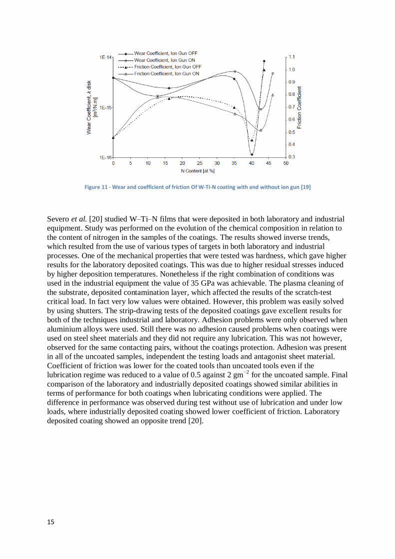
and critical load resulted in lowest wear coefficient and coefficient of friction. Film behaviour
during pin-on-disk test was not however, influenced by the surface roughness of the substrate
[19]. Wear and coefficient of friction curves of W–Ti–N films are shown on Figure 11,
showing the influence of increasing nitrogen content for depositions performed with and
without ion gun assistance.
15
Figure 11 - Wear and coefficient of friction Of W-Ti-N coating with and without ion gun [19]
Severo et al. [20] studied W–Ti–N films that were deposited in both laboratory and industrial
equipment. Study was performed on the evolution of the chemical composition in relation to
the content of nitrogen in the samples of the coatings. The results showed inverse trends,
which resulted from the use of various types of targets in both laboratory and industrial
processes. One of the mechanical properties that were tested was hardness, which gave higher
results for the laboratory deposited coatings. This was due to higher residual stresses induced
by higher deposition temperatures. Nonetheless if the right combination of conditions was
used in the industrial equipment the value of 35 GPa was achievable. The plasma cleaning of
the substrate, deposited contamination layer, which affected the results of the scratch-test
critical load. In fact very low values were obtained. However, this problem was easily solved
by using shutters. The strip-drawing tests of the deposited coatings gave excellent results for
both of the techniques industrial and laboratory. Adhesion problems were only observed when
aluminium alloys were used. Still there was no adhesion caused problems when coatings were
used on steel sheet materials and they did not require any lubrication. This was not however,
observed for the same contacting pairs, without the coatings protection. Adhesion was present
in all of the uncoated samples, independent the testing loads and antagonist sheet material.
Coefficient of friction was lower for the coated tools than uncoated tools even if the
lubrication regime was reduced to a value of 0.5 against 2 gm−2
for the uncoated sample. Final
comparison of the laboratory and industrially deposited coatings showed similar abilities in
terms of performance for both coatings when lubricating conditions were applied. The
difference in performance was observed during test without use of lubrication and under low
loads, where industrially deposited coating showed lower coefficient of friction. Laboratory
deposited coating showed an opposite trend [20].
16
2.4.2 DLC-Si
DLC (diamond-like carbon) coatings, similarly to the tungsten titanium coatings, are widely
used due to the great properties they show, such as low friction, high wear resistance, high
hardness, and chemical inertness. These properties are assigned to the bond that is created
between sp3 (diamond) and sp
2 (graphite). Ratio of this bond is largely affected by the
hydrogen presence in the coating therefore good ratio gives good properties. However, with
the rise of temperature the amount of hydrogen present decreases and graphitization occurs.
This causes poor thermochemical stability of such coatings. In order to keep the ratio of sp2
and sp3, but also decrease the amount of hydrogen present to enable coating to be usable at
higher temperatures, silicon is added to the coating. The effect silicon has on the structure is
that it does not form double bonds and therefore pushes carbon into the sp3 bonds. This is turn
gives better stability at higher temperatures and also decreases the energy of ion bombardment
during the PECVD (plasma-enhanced chemical vapour deposition) procedure. This is
important as high energy ion bombardment can result in intrinsic stress and limit the thickness
of the coating to few hundred nanometres for the coating to stay stable [21].
A study added hexamethyldisiloxane (HMDSO) to the gas mixture for the deposition of DLC
coating in order to test if any improvements are achieved in terms of mechanical properties of
the film. Diamond like film was prepared with incorporation of silicon. The mixture of gas for
the deposition process was comprised of methane, argon and HMDSO. Two coatings were
produced DLC/Si and DLC prepared with the mixture of argon and methane. The properties
of produced coatings were tested and showed that higher deposition rates can be achieved
when DLC/Si coatings are made. The rate for these coatings was 22-50nm/min while the
DLC coating without the incorporation of Si had the rate of 5nm/min. It should be mentioned
that higher deposition rate produces stable thicker coatings.
Compressive stresses were found for pure DLC films thicker than 0.9μm, which caused
wrinkling and delamination of the coating. This was not the case for the coatings deposited by
addition of HMDSO where no cracking was found and film thickness ranged from 1 to 5μm.
This shows great influence on fracture toughness without affecting mechanical properties of
the DLC coatings. Microindetation tests showed optimum hardness of 22GPa. These
properties remained unchanged up to the temperature of 400°C. However, beyond this
temperature structural changes occurred that decreased hardness and fracture toughness
properties. This result was observed when by annealing films deposited on silicon substrate
for 1 h at temperatures ranging from 250-450°C. Annealed films did not show delamination
and their load dependencies of effective microhardness compared to a coating that has not
been annealed is shown in Figure 12 [22].

17
Figure 12 - Effective hardness vs. applied load of annealed and not annealed films [22]
Ikeyama et al. [23] also studied the effect of Si doping on DLC films. For this study bipolar
pulse PBII system was used for the deposition of the coatings. To vary the content of Si, the
flow rate of tetramethylsilane (TMS) was controlled, and it varied from 0.0 to 3.5 sccm. For
coatings that had no TMS present during the deposition, the coefficient of friction was
relatively high, reaching a maximum value of 0.35. Also film adhesion to the substrate of
these coatings was not very good, as it easily peeled off. When the TMS flow rate was
increased to 1.0 sccm the effect was instantly visible. The coefficient of friction decreased by
more than half, reaching the value of 0.14, while showing good adhesion to the substrate.
However, with the additional increase of the TMS to 2.0 sccm the coefficient of friction
increased to 0.18 and then decreased again to 0.12 for 3.5 sccm of TMS. The increase of TMS
flow rate also had a decreasing effect on compressive internal stresses of the coating.
However, a negative influence of the TMS doping was shown in the gradual decrease of
hardness, for the flow up to 1.0 sccm, and drastic decrease for values above it. The hardness
value was also negatively affected by the increase of the silicon content, which is reasonable
as it was shown that Si content and the TMS flow rate have nearly linear relation. The ideal
doping of Si was then concluded to be between 1 and 2%, as with this values the hardness is
maintained at desirable values, adhesion is improved and internal stresses are decreased [23].
Baba et al. [24] performed a similar study with Si-DLC coatings deposited on silicon wafer
substrates, by DC glow discharge. The working gases for plasma used in this procedure were
acetylene and a mixture of tetramethylsilane (TMS). The deposited coatings showed very low
surface roughness and no special structure. In this case, the Si content of the coating was
nearly linearly related to the deposition rate. When Si content is compared to TMS flow rate,
strong increase in Si is shown at low fractions of TMS and stabilisation of Si is observed at
30at% of Si this is due to saturation of the coating with Si. This was assigned to the limitation
of the incorporation ability of Si in the DLC films. Thermal stability of the coating was tested
by annealing at temperatures 450°C, 500°C and 600°C. Si doping again showed to have
positive influence on thermal stability as no clear change was found between annealed
samples. The lowest coefficient of friction found in this study was at a value of 0.03 for the
24at% of Si in the coating. As it is shown on Figure 13, coefficient of friction lower than in

18
previous study were derived for all films (a - DLC. b - 9 at.% Si-DLC. c - 17 at.% Si-DLC. d -
24 at.% Si-DLC) even after 10,000 cycles [24].
Figure 13 - Coefficient of friction as a function of the number of rotations in the ball-on-disc [24]
DLC and Si-DLC based layer systems can also be deposited using magnetron sputtering. This
was shown in a study where industrial coating conditions were applied in combination with
intense ion bombardment in a special magnetron sputtered target configuration deposition. In
this procedure silicon was introduced by using silicon carbide as solid target material and both
DLC and Si-DLC based coatings were produced. Where Si-DLC coatings were carried out as
monolayers and Si-DLC/DLC nanolayers with silicon concentrations of up to 24 at.%.
Commonly discussed properties of coatings: wear resistance, hardness and coefficient of
friction have shown to be a function of hydrogen content for the DLC based coatings. This
deposition method allowed a decrease of hydrogen concentration in the coatings. Values
decreased down to 6 at.% for Si-DLC and to 10at.% for the DLC coating.
DLC coatings achieved low coefficient of friction of 0.15 and low wear rates of 0.6×10⁻¹⁵
m3m
−1 N
−1. For the Si-DLC based coatings at high silicon concentrations of more than 19
at.% coefficient of friction was even lower reaching values of 0.07. However, the abrasive
wear rate was affected by increasing the Si content with an increase from ~1×10⁻¹⁵
m3m
−1 N
−1
up to ~4×10⁻¹⁵
m3m−1
N−1
, as shown in Figure 14.
Figure 14 - Friction and abrasive wear of Si-DLC vs. silicon content [25]

19
In order to combine these two excellent properties of DLC and Si-DLC coatings i.e. the low
wear and coefficient of friction, a combined coating was produced. Coating was comprised of
layers with low Si-content followed by a Si-DLC with a high Si-content of up to 19 at.% Si.
This idea is schematically presented in Figure 15. In order to test the behaviour of these
coatings at high temperature, all coatings of various compositions and architectures were
annealed in the temperature range up to 500 °C. The results showed that the DLC coatings
can be used up to temperatures of 300 °C to 400 °C whereas the Si-DLC based coatings were
stable up to 500 °C. [25]
Figure 15 - Principle of wear and friction optimised Si-DLC based layer system [25]
20
3 Experimental methodology
3.1 Material and specimen
The test specimens analysed were two thin film coatings, W-Ti-N and DLC-Si. These
coatings were deposited using magnetron sputtering on steel substrates (100Cr6), consisting
of balls (d=10mm) and disks (d=30mm). The coatings were chosen for their self-lubricating
properties, low friction and wear behaviour and high hardness values. The deposition
conditions and the experimental characterisation techniques used to study these coatings are
described in the following sections.
The coatings were tested against aluminium alloy AA6061 samples. This alloy belongs to the
AA6xxx series, and it was selected due to similarities in mechanical properties and
composition of the most frequently used materials in warm forming [10].
3.2 Experimental techniques
3.2.1 Deposition
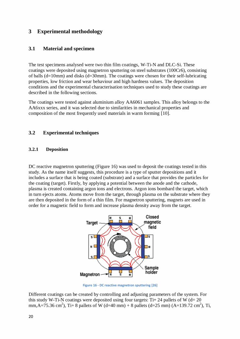
DC reactive magnetron sputtering (Figure 16) was used to deposit the coatings tested in this
study. As the name itself suggests, this procedure is a type of sputter depositions and it
includes a surface that is being coated (substrate) and a surface that provides the particles for
the coating (target). Firstly, by applying a potential between the anode and the cathode,
plasma is created containing argon ions and electrons. Argon ions bombard the target, which
in turn ejects atoms. Atoms move from the target, through plasma on the substrate where they
are then deposited in the form of a thin film. For magnetron sputtering, magnets are used in
order for a magnetic field to form and increase plasma density away from the target.
Figure 16 - DC reactive magnetron sputtering [26]
Different coatings can be created by controlling and adjusting parameters of the system. For
this study W-Ti-N coatings were deposited using four targets: Ti+ 24 pallets of W (d= 20
mm,A=75.36 cm2), Ti+ 8 pallets of W (d=40 mm) + 8 pallets (d=25 mm) (A=139.72 cm
2), Ti,
21
and W/Ti. Process was started by cleaning of the chamber for 10 min and then process of
deposition started at the pressure of 3x10⁻³
mbar and lasted for 45min. The power of targets
was kept constant at values of 700W for Ti target and 2000 W for rest of the targets. The
content of argon was 30sccm and 23.6sccm for nitrogen.
The DLC-Si coatings were deposited in a four magnetron Teer Coatings deposition chamber
using following four targets: one target of pure chromium, two of pure graphite and one of
pure silicon. The sputtered cleaning was done before the deposition lasting 20 minutes. To
improve the coating adhesion, a Cr interlayer of approximately 300 nm, was also deposited.
The content of silicon was controlled by the power supplied to silicon target, while graphite
targets had constant power throughout the process. The coatings were deposited with
increasing power applied on the Si target ranging from 0 to 580 W. DLC-Si coating used in
this study was deposited at the point when Si target received power of 350W. All carbon
targets were kept at constant power supply of 1750 W.
3.2.2 Characterisation
3.2.2.1 Chemical composition
The chemical composition of the coatings was determined by electron dispersive spectrometry
(EDS). Energy Dispersive Spectroscopy (EDS, also sometimes called EDX - Energy
Dispersive X-ray Analysis) is the most frequently used chemical analysis tool. It is used as an
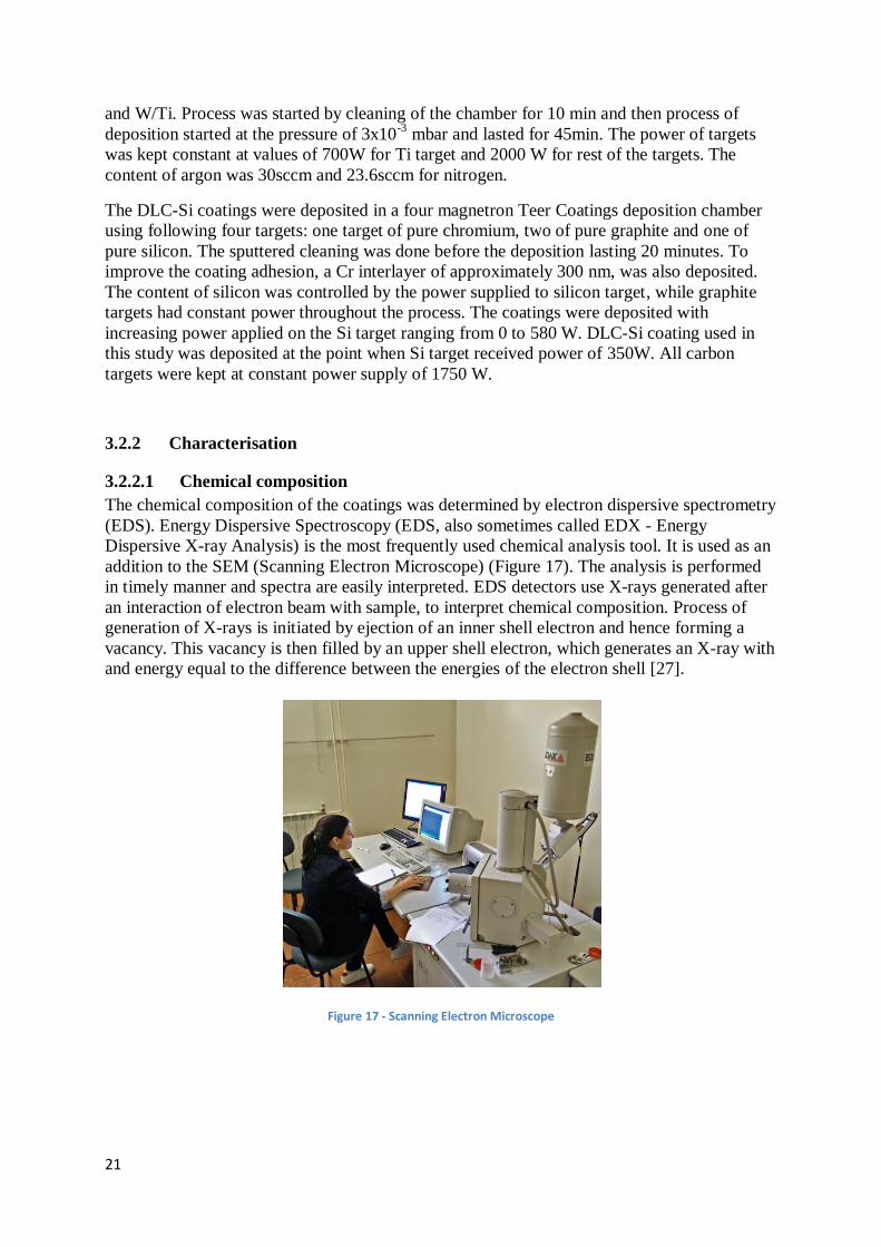
addition to the SEM (Scanning Electron Microscope) (Figure 17). The analysis is performed
in timely manner and spectra are easily interpreted. EDS detectors use X-rays generated after
an interaction of electron beam with sample, to interpret chemical composition. Process of
generation of X-rays is initiated by ejection of an inner shell electron and hence forming a
vacancy. This vacancy is then filled by an upper shell electron, which generates an X-ray with
and energy equal to the difference between the energies of the electron shell [27].
Figure 17 - Scanning Electron Microscope

22
3.2.2.2 Hardness and Young’s modulus
The hardness and Young’s modulus of the coatings were assessed by depth-sensing
indentation technique (Micro Materials NanoTest) using a Berkovich diamond pyramid
indenter, under 5-10 mN applied load. This type of indentation tip has a three sided geometry.
Exact values of this geometry have to be known, as indentation created by it is only a few
square micrometres or even nanometres large. This makes it difficult to interpret as contact
area is hard to determine. Therefore during the process of indentation, depth of penetration is
recorded along with other parameters, such as load. This way contact area is easily
determined using the know geometry. Load vs. displacement curves can also be obtained in
order to calculate the hardness of the material as well as other mechanical properties. The
slope of the unloading part of the curve indicates stiffness of the material, which is then used
to derive reduced Young’s modulus values [28].
Figure 18 - Nanoindentation equipment [29]
3.2.2.3 Structure
The crystal structure of the coatings was evaluated by X-ray diffraction (XRD) using a X’Pert
(from Philips) apparatus with Co Kα (λ = 0.178897 nm) radiation (Figure 19). X-ray
diffraction (XRD) is a technique used to study crystal structures and atomic spacing. It is
based on constructive interference of monochromatic X-rays and a crystalline sample.
Incident X-rays are produced by a cathode ray tube. This procedure is based on Bragg's Law
and when satisfying conditions are achieved, the interaction of the incident rays with the
sample produces constructive interference. Diffracted X-rays are then detected, processed and
counted. The sample is scanned through a range of 2θ angles where all possible diffraction
directions of the lattice are attained, even in case of a random orientation of a particular
material [30].

23
Figure 19 - X'Pert by Philips [31]
3.2.2.4 Tribological Characterisation
The experimental method used is the pin-on-disk test, which represents a typical pin-on-disk
or ball-on-flat contact, where the pin on the equipment is held stationary and the disk beneath
it is moving. Hence, the contact location moves with a velocity relative to the stationary
contact area [32]. Figure 20 presents a schematic representation of the test. The pressure
achieved at the contact point is dependent on the force of the pin, which is controlled by
adding weights on it. The coefficient of friction can be evaluated based of the normal and
tangential force, by connecting the equipment to a computer and using specialised software.
Figure 20 - Schematic diagram of typical pin-on-disk equipment [32]
Tests using this equipment were performed at three different temperatures: room temperature
(~24°C), 100°C and 200°C. The force used was 2N for all samples and each test was
performed for 500 cycles, at a speed of 0.1m/s.
As previously mentioned both balls and disks, needed for this test were coated. Thus, it was
possible to perform tests with both, i.e. coated pins against aluminium disks and aluminium
balls against coated disks. For comparison purposes, tests with uncoated 100Cr6 balls and
disks were also performed against aluminium disk and an aluminium ball, respectively.
24
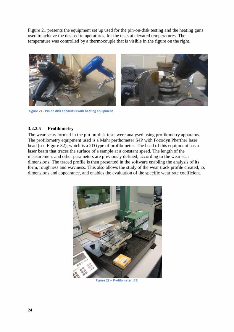
Figure 21 presents the equipment set up used for the pin-on-disk testing and the heating guns
used to achieve the desired temperatures, for the tests at elevated temperatures. The
temperature was controlled by a thermocouple that is visible in the figure on the right.
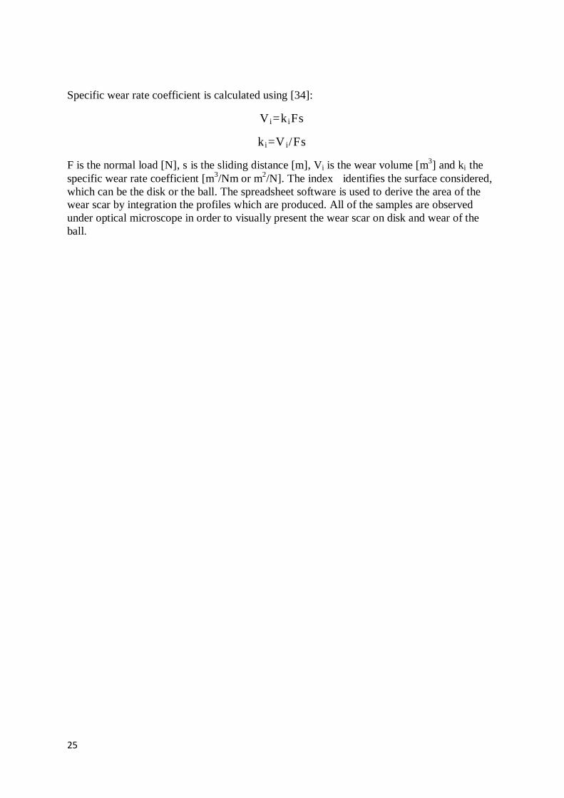
3.2.2.5 Profilometry
The wear scars formed in the pin-on-disk tests were analysed using profilometry apparatus.
The profilometry equipment used is a Mahr perthometer S4P with Focodyn Pherther laser
head (see Figure 32), which is a 2D type of profilometer. The head of this equipment has a
laser beam that traces the surface of a sample at a constant speed. The length of the
measurement and other parameters are previously defined, according to the wear scar
dimensions. The traced profile is then presented in the software enabling the analysis of its
form, roughness and waviness. This also allows the study of the wear track profile created, its
dimensions and appearance, and enables the evaluation of the specific wear rate coefficient.
Figure 22 – Profilometer [33]
Figure 21 - Pin on disk apparatus with heating equipment
25
Specific wear rate coefficient is calculated using [34]:
V i=k iFs
k i=V i/Fs
F is the normal load [N], s is the sliding distance [m], Vi is the wear volume [m3] and ki the
specific wear rate coefficient [m3/Nm or m
2/N]. The index identifies the surface considered,
which can be the disk or the ball. The spreadsheet software is used to derive the area of the
wear scar by integration the profiles which are produced. All of the samples are observed
under optical microscope in order to visually present the wear scar on disk and wear of the
ball.

26
4 Results and discussion
4.1 Chemical and mechanical analysis
Chemical composition and mechanical analysis (hardness and Young’s modulus) of the W-Ti-
N and DLC-Si coatings are summarised and presented in the Tables 1 and 2, respectively.
Table 1 - Chemical composition W-Ti-N
W-Ti-N Chemical composition (%) Thickness
[μm] Hardness
[GPa] Young’s
Modulus [GPa]
W Ti N W/Ti 1
26
( 1.1)
292
( 9.5) 39.3 27.8 32.9 1.41
The values of hardness and Young’s modulus for the W-Ti-N coating are nearly two times
smaller than the ones obtained for the same coating, deposited on steel substrate in other
studies [20,21]. In fact, the hardness value is more similar to the one obtained for a W-Ti-N
coating deposited on 42CrMo4 substrate, with ion gun assistance and partial pressure ratio of
N2/Ar at 0.5 and M2 (AISI) steel, at equal partial pressure ratio [18,15].
Table 2 - Chemical composition DLC-Si
DLC-Si Chemical composition (%) Thickness
[μm] Hardness
[GPa] Young’s
Modulus [GPa]
C Si O Ar 1.2
19
( 0.51)
204
( 4.5) 81.9 14.4 0.3 3.4
The hardness of the DLC-Si coating is similar to the one obtained for the same coating
deposited on steel. However, those studies presented much smaller amounts of Si, for
example about 5% [25] or 0% of TMS addition [23]. Both hardness and Young’s modulus can
be compared to the values reported by Buršíková [22], where the hardness of the film
deposited without annealing was similar to ones obtained in this study. However, the Young’s
modulus value is 1/3 smaller than the value presented in Table 2.

27
4.2 Structure
The structure of the W-Ti-N coating is presented in Figure 23. The XRD pattern of the W-Ti-
N coating shows high sharp peaks of TiN (FCC structure, ICDD card no. 87-0633) and peaks
of W2N (ICDD card no. 25-1257) less intense but, nevertheless still present. From the curve
and position of the annotations of the peaks, there is a clear shift of the peaks to the left, i.e. to
lower diffraction angles. This can be assigned to residual compressive stresses in the coating.
The same behaviour was found by Braga et al. [16] in their study of W-Ti-N coating.
Figure 23 - XRD pattern for W-Ti-N coating
The structure of the DLC-Si coating is presented in Figure 24. The DLC-Si coating shows an
intense and narrow diffraction peak ascribed to Cr cubic phase (ICDD card no. 85-1336 ) and
some less intense peaks, corresponding to the SiC hexagonal phase (ICDD card no. 75-1541) .
No other diffraction peaks were detected, which indicates that the DLC coating is amorphous.
Amorphous structure was also found in the study by Hofmann et al. [25]. The peak for
chromium content is very high due to the interlayer that was deposited to improve adhesion.

28
Figure 24 - XRD pattern for DLC-Si coating
4.3 Pin-on-disk
The aim of this study was to evaluate the behaviour of two different coatings using the pin-
on-disk test in dry conditions, in order to describe their tribological behaviour for warm
forming process in laboratory conditions.
Figure 25 shows the coefficient of friction for W-Ti-N coated disks for different temperatures.
For coated disks, the coefficient of friction does not change considerably when tests are
performed at room temperature and 100°C. This is in accordance to the results found in other
studies, considering W-Ti-N coated disks, where the average value for the coefficient of
friction was recorded to be about 0.7, for the same percentage of nitrogen in the coating as in
the ones produced for this study [19].
The coefficient of friction values decrease when temperature is raised to 200°C, to an average
value of approximately 0.5. This is the type of behaviour that was expected and desired: a
decrease of the coefficient of friction at temperatures appropriate for warm forming process.
-0,2
0
0,2
0,4
0,6
0,8
1
1,2
1,4
1,6
0 50 100 150 200 250 300
Co
efi
cie
nt
of
fric
tio
n
Time (s)
W-Ti-N disk 22°C W-Ti-N disk 100°C W-Ti-N disk 200°C
Figure 25 - Coefficient of friction curves for W-Ti-N coated disks
29
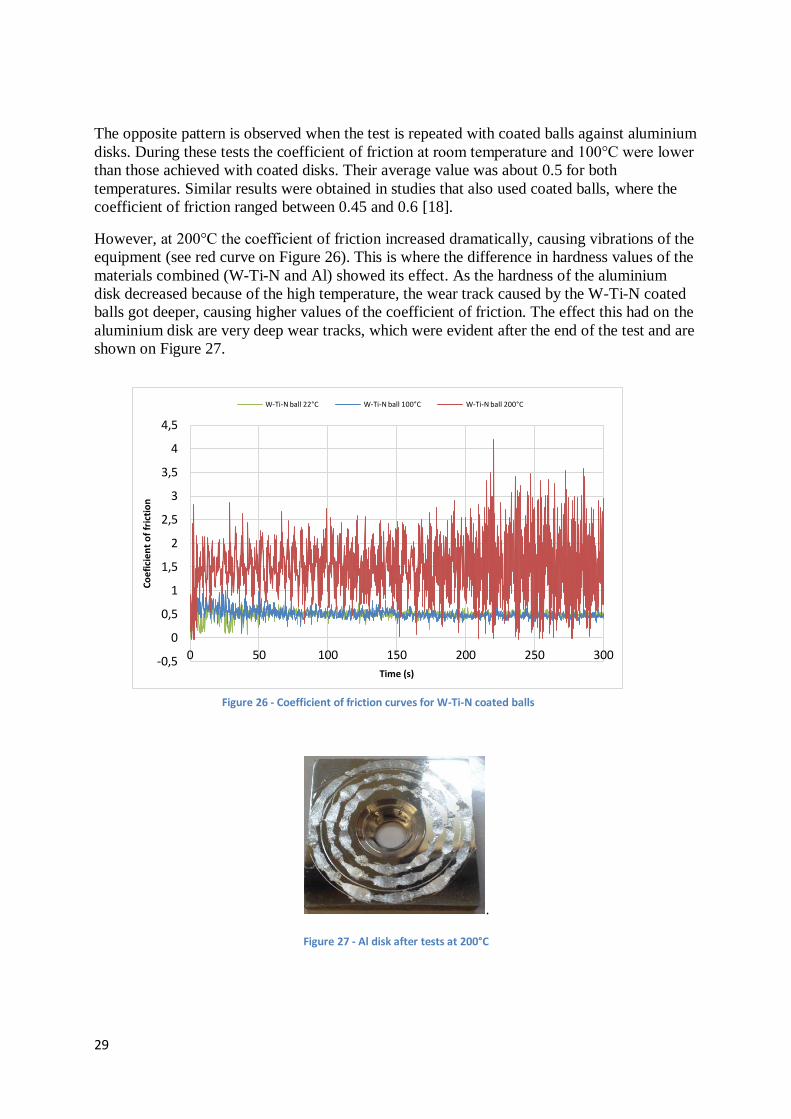
The opposite pattern is observed when the test is repeated with coated balls against aluminium
disks. During these tests the coefficient of friction at room temperature and 100°C were lower
than those achieved with coated disks. Their average value was about 0.5 for both
temperatures. Similar results were obtained in studies that also used coated balls, where the
coefficient of friction ranged between 0.45 and 0.6 [18].
However, at 200°C the coefficient of friction increased dramatically, causing vibrations of the
equipment (see red curve on Figure 26). This is where the difference in hardness values of the
materials combined (W-Ti-N and Al) showed its effect. As the hardness of the aluminium
disk decreased because of the high temperature, the wear track caused by the W-Ti-N coated
balls got deeper, causing higher values of the coefficient of friction. The effect this had on the
aluminium disk are very deep wear tracks, which were evident after the end of the test and are
shown on Figure 27.
.
Figure 27 - Al disk after tests at 200°C
-0,5
0
0,5
1
1,5
2
2,5
3
3,5
4
4,5
0 50 100 150 200 250 300
Co
efi
cie
nt
of
fric
tio
n
Time (s)
W-Ti-N ball 22°C W-Ti-N ball 100°C W-Ti-N ball 200°C
Figure 26 - Coefficient of friction curves for W-Ti-N coated balls

30
When the samples were observed using optical microscope, a clear transfer layer of
aluminium was present on the coated balls, for all temperatures. This indicates problems with
adhesion, which is common behaviour for a soft material such as aluminium alloy used in this
study. Such soft materials easily shred a layer on counter material at high pressures. Adhesive
wear is commonly found in frictional contacts between surfaces and is generally referred to as
unwanted attachment of the material from counter surface in the contact. The same problem
was reported by Silva et al. [18], when W-Ti-N coated balls were tested against Al and Zn
alloys, in lubricated and non-lubricated conditions. They found adhesion of Al on the coated
balls for both conditions [18].
Aluminium adhesion layer was present on all W-Ti-N coated balls, even at elevated
temperatures, when self-lubricating properties were expected to act as a liquid lubricating
layer between the pin and the disk. However, the transfer of material is not visible on coated
disks, which were tested against aluminium balls. In that case the wear of the balls is evident,
especially for the test performed at 200°C, where lines of the wear track are clearly visible on
the micrograph. Micrographs of both coated balls and disks and matching aluminium balls
and disks are presented on Figures 28 and 29.
a b c
Figure 28 - Micrographs of W-Ti-N coated balls and Al disks a) 22°C, b) 100°C, c) 200°C

31
a b c
Figure 29 – Micrographs of Al balls and W-Ti-N coated disks a) 22°C, b) 100°C, c) 200°C
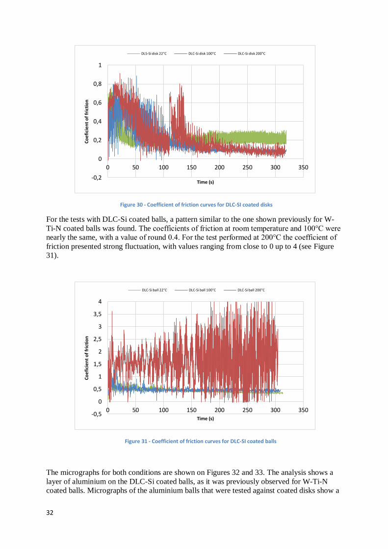
The experimental tests were repeated for the DLC-Si coating, under the same conditions. A
pattern was found for the evolution of the coefficient of friction, where the run-in phase is
clearly visible. As shown in Figure 30, the coefficient of friction for coated disks starts at
higher values but, quickly decreased to values of about 0.2, after the first 20s of the test. The
average coefficients of friction obtained are of lower values when compared to W-Ti-N disks.
The values obtained for the coefficients of friction are in accordance with other studies on
DLC coatings with Si content, at room temperature. Such studies presented the coefficients of
friction values between 0.12 and 0.25, depending on the amount of Si present in the coating
[23]. In the study by Hofmann et al. [25], where DLC and Si-DLC coatings were annealed up
to a temperature of 500°C, the coefficients of friction at 200°C were lower than the ones
achieved in this study, with values of about 0.11. However, these results were deducted from
the step stress test [25].
32
Figure 30 - Coefficient of friction curves for DLC-SI coated disks
For the tests with DLC-Si coated balls, a pattern similar to the one shown previously for W-
Ti-N coated balls was found. The coefficients of friction at room temperature and 100°C were
nearly the same, with a value of round 0.4. For the test performed at 200°C the coefficient of
friction presented strong fluctuation, with values ranging from close to 0 up to 4 (see Figure
31).
Figure 31 - Coefficient of friction curves for DLC-SI coated balls
The micrographs for both conditions are shown on Figures 32 and 33. The analysis shows a
layer of aluminium on the DLC-Si coated balls, as it was previously observed for W-Ti-N
coated balls. Micrographs of the aluminium balls that were tested against coated disks show a
-0,2
0
0,2
0,4
0,6
0,8
1
0 50 100 150 200 250 300 350
Co
efi
cie
nt
of
fric
tio
n
Time (s)
DLS-Si disk 22°C DLC-Si disk 100°C DLC-Si disk 200°C
-0,5
0
0,5
1
1,5
2
2,5
3
3,5
4
0 50 100 150 200 250 300 350
Co
efi
cie
nt
of
fric
tio
n
Time (s)
DLC-Si ball 22°C DLC-Si ball 100°C DLC-Si ball 200°C

33
clear difference in wear, when compared to those that were tested against W-Ti-N coating, as
the wear tracks are not as apparent.
Figure 32 - Micrograph of DLC-Si coated balls and Al disks a) 22°C, b) 100°C, c) 200°C
Figure 33 - Micrograph of Al balls and DLC-Si coated disks a) 22°C, b) 100°C, c) 200°C
For comparison purposes tests with steel balls and steel disks were also performed. Figures 34
and 35 present the average value of the coefficients of friction, calculated for all samples, and
compared separately for coated and uncoated balls and coated and uncoated disks.
a b c
a b c

34
The behaviour of all coated and steel balls is very similar. This can be explained by the
adhesion of the aluminium layer that formed on all coated and steel balls. This resulted in
obtaining the values of coefficient of friction between the aluminium layer on the ball and the
aluminium disk. Rather than presenting the coefficient of friction between the coating or steel
and the aluminium.
For the coated disks, the coefficient of friction was lowest for DLC-Si coating, throughout the
conditions. The difference in the average coefficient of friction is evident when compared to
W-Ti-N coated disk. Also, the average coefficient of friction for DLC-Si coating does not
change drastically throughout the temperature change, which is not the case for the W-Ti-N
coating. W-Ti-N coating showed higher average values of coefficient of friction than both
DLC-Si coating and uncoated steel ball, from room temperature up to 100°C. However
uncoated steel ball and W-Ti-N ball showed similar results at 200°C, with values below 0.6.
In the study by Silva et al. [35] 100Cr6 balls and W-Ti-N coated balls were tested against
stamping sheets materials and coefficient of friction was obtained. Similarly to results in
Figure 35, it showed slightly higher or similar results obtained by uncoated ball, when
compared with W-Ti-N coated balls at room temperature; especially when DDS steel was
used [18].
Figure 35 - Coefficient of friction for coated and steel disks Figure 34 - Coefficient of friction for coated and steel balls
0
0,5
1
1,5
2
25 100 200
Co
efi
cie
nt
of
fric
tio
n
Temperature (°C)
Coated and steel balls
0
0,2
0,4
0,6
0,8
1
25 100 200
Co
efi
cie
nt
of
fric
tio
n
Temperature (°C)
Coated and steel disks

35
4.4 Profilometry
The figures of the aluminium disks, shown in previous sections, indicate that the wear profiles
obtained on aluminium disks are very deep. This analysis was confirmed, as shown by the
profiles obtained using the profilometer, which are presented in Tables 3 and 4, along with the
calculated wear rate.
The deepest profile was observed for the wear track created by DLC-Si coated ball, at the
temperature of 200°C, with a depth of the profile of 100μm. For the W-Ti-N coated ball, at
the same temperature, the profile was somewhat shallower, with a maximum value of 50μm.
However, wear profiles created by DLC-Si coated balls at room temperature and 100°C were
shallower that those of W-Ti-N coated balls, which were twice as deep, with maximum values
of approximately 10μm.
Table 3 - Profilometry and wear rate of wear tracks on Al disks (W-Ti-N balls)
22°C Wear rate (m2/N)
2.5x10⁻⁹
100°C
5.3 x10⁻⁹
200°C
22 x10-9
36
Table 4 - Profilometry of wear tracks on Al disks (DLC-Si balls)
The comparison, of the results obtained for the tests performed with steel ball and aluminium
disk, shows a resemblance to the ones obtained for aluminium disk tested against DLC-Si
coated balls. The depths of those profiles are around 10μm for room temperature and 100°C,
increasing to 100μm for 200°C.
The wear rate values presented in Tables 3 and 4 are compared in Figures 36 and 37. As the
aluminium disks were very worn and damaged by the test, as expected the wear rate is quite
high, especially for the tests performed at the temperature of 200°C. The values for DLC-Si
coating and steel are four times higher than those observed for W-Ti-N coating, at 1x10⁻⁷
m2/N
and 1.2x10⁻⁷
m2/N. The values for W-Ti-N coating remained low for all the temperatures
tested compared to other two cases.
22°C Wear rate (m2/N)
0.6 x10⁻⁹
100°C
0.04 x10⁻⁹
200°C
120 x10-9
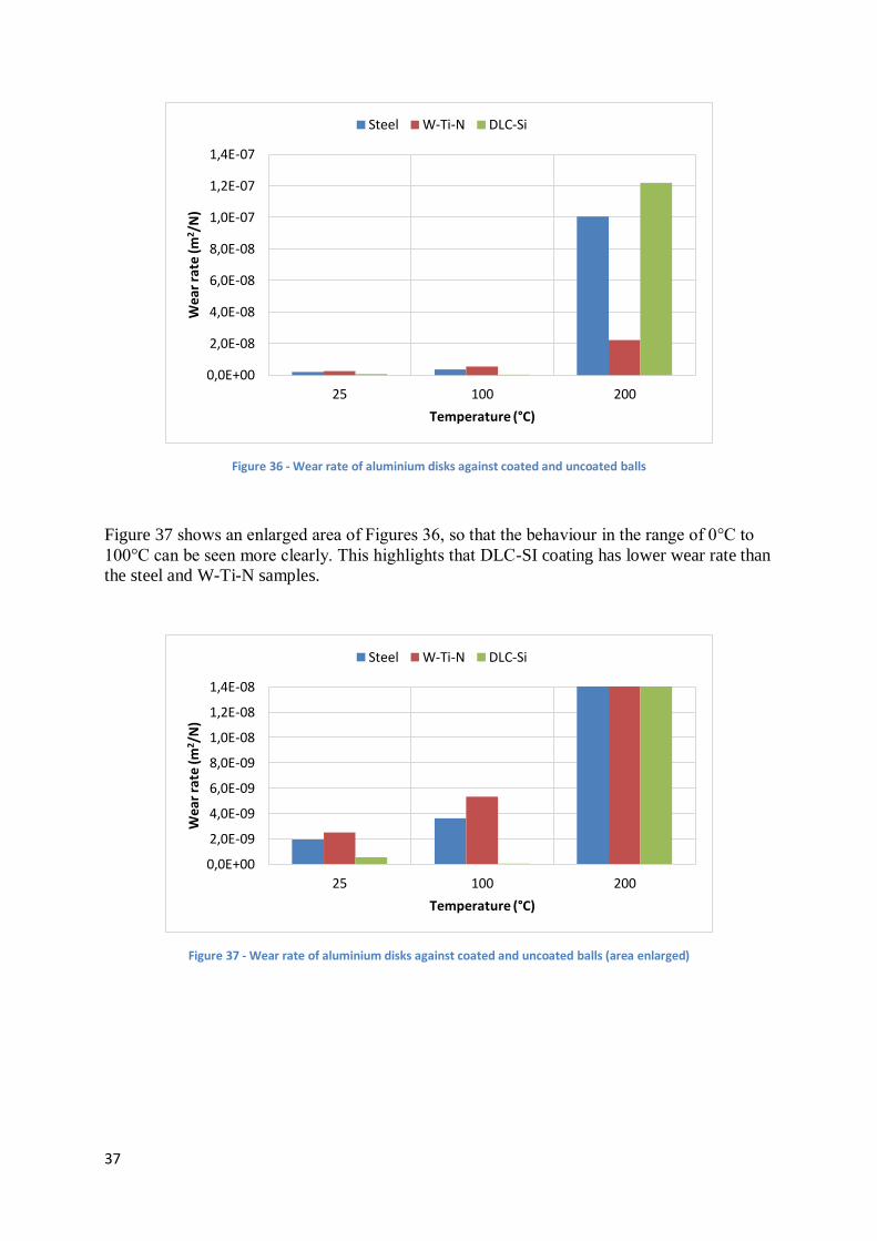
37
Figure 36 - Wear rate of aluminium disks against coated and uncoated balls
Figure 37 shows an enlarged area of Figures 36, so that the behaviour in the range of 0°C to
100°C can be seen more clearly. This highlights that DLC-SI coating has lower wear rate than
the steel and W-Ti-N samples.
Figure 37 - Wear rate of aluminium disks against coated and uncoated balls (area enlarged)
0,0E+00
2,0E-08
4,0E-08
6,0E-08
8,0E-08
1,0E-07
1,2E-07
1,4E-07
25 100 200
Wea
r ra
te (
m2 /
N)
Temperature (°C)
Steel W-Ti-N DLC-Si
0,0E+00
2,0E-09
4,0E-09
6,0E-09
8,0E-09
1,0E-08
1,2E-08
1,4E-08
25 100 200
Wea
r ra
te (
m2/N
)
Temperature (°C)
Steel W-Ti-N DLC-Si
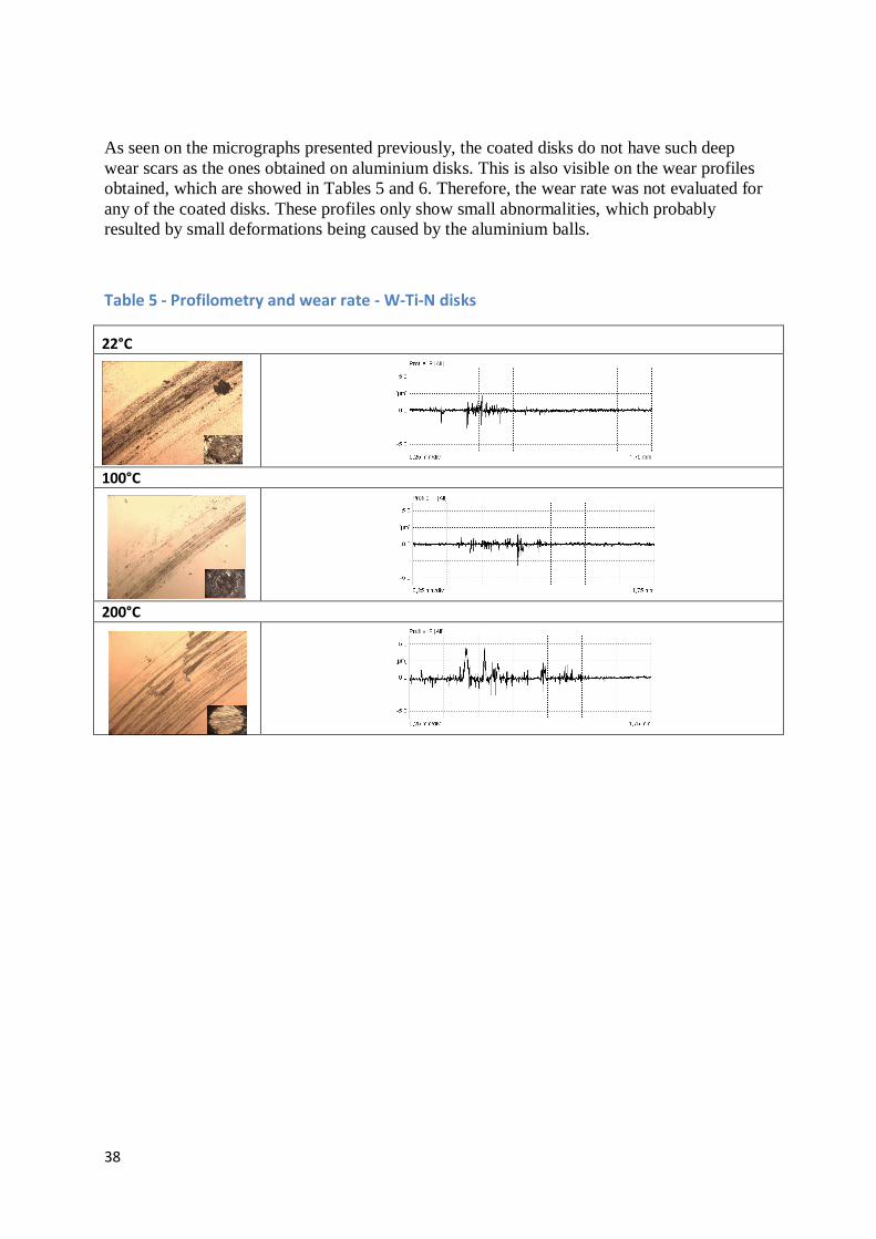
38
As seen on the micrographs presented previously, the coated disks do not have such deep
wear scars as the ones obtained on aluminium disks. This is also visible on the wear profiles
obtained, which are showed in Tables 5 and 6. Therefore, the wear rate was not evaluated for
any of the coated disks. These profiles only show small abnormalities, which probably
resulted by small deformations being caused by the aluminium balls.
Table 5 - Profilometry and wear rate - W-Ti-N disks
22°C
100°C
200°C

39
Table 6 - Profilometry and wear rate - DLC-Si disks
The wear rate of the aluminium balls is summarized in Figure 38.
Figure 38 - Wear rate of aluminium balls against coated and uncoated disks
0,0E+00
5,0E-08
1,0E-07
1,5E-07
2,0E-07
2,5E-07
25 100 200
Wea
r ra
te (
m2 /
N)
Temperature (°C)
Steel W-Ti-N DLC-Si
22°C
100°C
200°C

40
As previously shown in the micrographs, the aluminium ball that was tested against W-Ti-N
coating at 200°C shows the highest wear rate. However, at room temperature and at 100°C,
the aluminium balls tested against both W-Ti-N and DLC-Si coating, show similar wear rates
values, of about 3.4x10⁻⁹
m2/N and 2.7x10
-9 m
2/N (see detailed analysis in Figure 39).
Aluminium balls tested on uncoated steel disk show higher values, except in the previously
mentioned case of W-Ti-N coating at 200°C.
Figure 39 - Wear rate of aluminium balls against coated and uncoated disks (area enlarged)
-5,0E-09
1,4E-22
5,0E-09
1,0E-08
1,5E-08
2,0E-08
25 100 200
We
ar r
ate
(m
2 /N
)
Temperature (°C)
Steel W-Ti-N DLC-Si

41
5 Conclusion and future work
In this study, the behaviour of two different coatings was studied for the purposes of warm
forming. The coatings analysed include chemical elements (Ti and Si) that can form Magnéli
oxides phases, which showed self-lubricating properties when used at high temperatures. Such
behaviour is due to their easily shearable planes. Two coatings were chosen, W-Ti-N and
DLC-Si, and their tribological behaviour was accessed using pin-on-disk tests, performed on
both coated balls and disks, at room temperature, 100°C and 200°C. The counter material for
the test was the AA6016 aluminium alloy. Two different sets of results were obtained from
the study: the coefficient of friction and the wear rate.
The desired behaviour of the coating was that the Magnély oxides of the titanium and silicon
compounds would perform as liquid lubricants and prevent the formation of the transfer layer
of aluminium alloy. Aluminium alloy is a soft material and experiences adhesion problems,
previously reported in other studies. Unfortunately, this has proven to be the case when coated
balls (both DLC and W-Ti-N) were tested against the aluminium disk. A clear layer of
aluminium was shown on the micrographs taken at the end of the test, indicating that the
contact achieved by the pin-on-disk test was between the aluminium layer and aluminium disk
and not between the coating and the aluminium alloy. The layer of aluminium also disabled
the calculation of the wear rate of the coated balls, as the wear crater was not clearly visible.
This does not represent the results we were hoping to achieve and study. However, these
conditions may not represent the real behaviour of the coatings in the industrial environment
and, consequently, they can be considered less relevant. In fact, in the warm forming process
the coated tools will be submitted to contact always with a new blank. There is always some
sliding of the aluminium blank along the tools, particularly in die shoulder, but the conditions
do not seem to be as critical as the ones used in the pin-on-disk test.
Therefore, a better representation of the contact conditions between the coatings and the
aluminium alloy was obtained using the coated disks. In this set of tests DLC-Si coated disks
showed better results for the coefficient of friction and no wear rate was observed throughout
the temperature range. These results indicate that if these coatings are used in combination
with aluminium alloys they would enable a smooth and fast running process and a tool that
would experience very little wear and deformation.
The W-Ti-N coated disks showed decreasing values of both the coefficient of friction and the
wear rate for the test performed at the temperature of 200°C. This might imply that they
would be more suitable for higher temperatures than the ones tested in this study. As warm
forming can be performed in a range of temperatures from 100°C to 350°C, this might be a
starting point for future studies.
Considering that all coated pins showed adhesion problems, a future work could be to
repeated a similar study to the one performed by Silva et al. [18], with the DLC-Si coatings,
as with W-Ti-N coatings adhesion problems were already observed. This involves testing in
lubricated conditions with lubricants used in industry. Decreasing amounts can be considered
to determine the lowest amount of lubricant needed for a contact not to develop a transfer
layer. This way compromise can be achieved by decreasing the quantity of lubricants used in
the industry.

42
6 Bibliography
[1] E. P. a. t. Council, Directive 2008/1/EC concerning integrated pollution prevention and control.
[2] W. S. Miller, L. Zhuang, J. Bottema, A. Wittebrood, P. De Smet and A. Haszler, “Recent
development in aluminium alloys for the automotive industry,” Materials Science and
Engineering, vol. 280, no. 1, pp. 37-49, 2000.
[3] Ducker Worldwide, “Drive Aluminium,” The Aluminum Association, 2015. [Online]. Available:
www.drivealuminum.org/vehicle-uses. [Accessed June 2015].
[4] A. van den Boogaard and J. Huétink, “Simulation of aluminium sheet forming at elevated
temperatures,” Computer methods in applied mechanics and engineering, vol. 195, pp. 6691-
6709, 2006.
[5] M. Merklein and J. Lechler, “Determination of material and process characteristics for hot
stamping processes of quenchable ultra high strength steels with respect to a FE-based process
design,” SAE International Journal of Materials and Manufacturing, vol. 117, pp. 411-426, 2009.
[6] H. Karbasian and A. Tekkaya, “A Review on Hot Stamping,” Journal of Materials Processing
Technology, vol. 210, pp. 2103-2118, 2010.
[7] J. Aspacher, “Forming hardening concepts,” 1st International Conference on Hot Sheet Metal
Forming of High-Performance Steel, Kassel, Germany, pp. 77-81, 2008.
[8] E. M. Taleff, P. J. Nevland and K. P. E., “Tensile ductility of several commercial aluminum alloys at
elevated temperatures,” Metallurgical and Materials Transactions, vol. 32A, pp. 1119-1130,
2001.
[9] J. K. Chang, K. Takata, K. Ichitani and E. M. Taleff, “Ductility of an Aluminum-4.4 wt. pct.
Magnesium Alloy at Warm- and Hot-working Temperatures,” Materials Science and Engineering,
vol. A 257, pp. 3822-3828, 2010.
[10] P. F. Bariani, S. Bruschi, A. Ghiotti and F. Michieletto, “Hot stamping of AA5083 aluminium alloy
sheets,” CIRP Annals - Manufacturing Technology, vol. 62, pp. 251-254, 2013.
[11] M. S. Mohamed, A. D. Foster, J. Lin, D. S. Balint and T. A. Dean, “Investigation of Deformation
and Failure Features in Hot Stamping of AA6082: Experimentation and Modelling,” International
Journal of Machine Tools and Manufacture, vol. 53, pp. 27-38, 2012.
[12] A. Ghiotti, S. Bruschi and F. Borsetto, “Tribological characteristics of high strength steel sheets
under hot stamping conditions,” Journal of Materials Processing Technology, vol. 211, pp. 1694-
1700, 2011.
[13] B. Krause, “The fabricator,” International Fabricators & Manufacturers, December 2007.
[Online]. Available: http://www.thefabricator.com/article/stamping/tooling-for-forming-high-
43
strength-material. [Accessed June 2015].
[14] Y. Sun and T. Bell, “Plasma surface engineering of low alloy steel,” Materials Science and
Engineering, vol. A 140, pp. 419-434, 1991.
[15] B. Podgornik, J. Vižintin, O. Wänstrand, M. Larsson and S. Hogmark, “Wear and friction
behaviour of duplex-treated AISI 4140 steel,” Surface and Coatings Technology, Vols. 120-121,
pp. 502-508, 1999.
[16] D. Braga, J. P. Diasa and A. Cavaleiro, “Duplex treatment: W–Ti–N sputtered coatings on pre-
nitrided low and high alloy steels,” Surface and Coatings Technology, vol. 200, pp. 4861-4869,
2006.
[17] O. M. Carlsson P., “PVD coatings for sheet metal forming processes—a tribological evaluation,”
Surface and Coatings Technology, vol. 200, pp. 4654-4663, 2006.
[18] P. N. Silva, J. P. Dias and A. Cavaleiro, “Performance of W–TI-(N) coated pins in lubricated pin-on-
disk tests,” Surface and Coatings Technology, vol. 202, pp. 2338-2343, 2008.
[19] P. N. Silva, J. P. Dias and A. Cavaleiro, “Tribological behaviour of W–Ti–N sputtered thin films,”
Surface and Coatings Technology, vol. 200, pp. 186-191, 2005.
[20] V. Severo, L. Vilhena, P. N. Silva, J. P. Dias, D. Becker, S. Wagner and A. Cavaleiro, “Tribological
behaviour of W–Ti–N coatings in semi-industrial strip-drawing tests,” Journal of Materials
Processing Technology, vol. 209, no. 10, pp. 4662-4667, 2008.
[21] C. De Martino, G. Fuscb, G. Mina, A. Tagliaferro, L. Vanzetti, L. Calliari and M. Anderle,
“Improvement of mechanical properties of a-C:H by silicon addition,” Diamond and Related
Materials, vol. 6, no. 5-7, pp. 559-563, 1997.
[22] V. Buršíková, V. Navrátil, L. Zajíáčková and J. Janča, “Temperature dependence of mechanical
properties of DLC/Siprotective coatings prepared by PECVD,” Materials Science and Engineering,
vol. A324 , pp. 251-254, 2002.
[23] M. Ikeyama, S. Nakao, Y. Miyagawa and S. Miyagawa, “Effects of Si content in DLC films on their
friction and wear properties,” Surface and Coatings Technology, vol. 119, pp. 38-42, 2005.
[24] K. Baba, R. Hatada, S. Flege and E. W., “Deposition of silicon-containing diamond-like carbon
films by plasma-enhanced,” Surface and Coatings Technology, vol. 203, pp. 2747-2750, 2009.
[25] D. Hofmann, S. Kunkel, K. Bewilogua and R. Wittor, “From DLC to Si-DLC based layer systems
with optimized properties for tribological applications,” Surface and Coatings Technology, vol.
215, pp. 357-363, 2013.
[26] “Adachi,” [Online]. Available: http://www.adachi-
new.com/archives/product/dlc_coating?pt=49. [Accessed June 2015].

44
[27] P. D. Ngo, “Energy Dispersive Spectroscopy,” The Springer International Series in Engineering
and Computer Science, vol. 494, pp. 205-215, 1999.
[28] W. C. Oliver and G. M. Pharr, “Measurement of hardness and elastic modulus by instrumented
indentation: Advances in understanding and refinements to methodology,” Journal of Materials
Research, vol. 19, pp. 3-20, 2004.
[29] M. M. Limited, “NanoTest Vantage,” Micro Materials, [Online]. Available:
http://www.micromaterials.co.uk/the-nano-test/nanotest-vantage/. [Accessed July 2015].
[30] B. L. Dutrow, “Geochemical Instrumentation and Analysis,” June 2015. [Online]. Available:
http://serc.carleton.edu/research_education/geochemsheets/techniques/XRD.html. [Accessed
July 2015].
[31] “PANalytical,” [Online]. Available: http://www.panalytical.com/XPert3-MRD-XL.htm. [Accessed
June 2015].
[32] F. E. Kennedy, Y. Lu and I. Baker, “Contact temperatures and their influence on wear during pin-
on-disk tribotesting,” Tribology International, vol. 82, pp. 534-542, 2015.
[33] Mahr, “Cottrill and Co.,” [Online]. Available: http://www.cottandco.com/en/lots/mahr-pertmen-
type-pst-nse-perthometer-prn. [Accessed June 2015].
[34] Archard, “CALCULATION OF WEAR RATE,” Tribology ABC, 1953. [Online]. Available:
http://www.tribology-abc.com/abc/wear.htm. [Accessed June 2015].
[35] P. N. Silva, J. P. Dias and A. Cavaleiro, “Performance of W–TI-(N) coated pins in lubricated pin-on-
disk tests,” Surface & Coatings Technology, vol. 202, pp. 2338-2343, 2008.
[36] F. Fernandes, A. Loureiro, I. Polcar and A. Cavaleiro, “The effect of increasing V content on the
structure, mechanical properties and oxidation resistance of Ti–Si–V–N films deposited by DC
reactive magnetron sputtering,” Applied Surface Science, vol. 289, pp. 114-123, 2014.
[37] K. Dohda and T. Aizawa, “Tribo-characterization of silicon doped and nano-structured DLC
coatings by metal forming simulators,” Manufacturing Letters, vol. 2, pp. 82-85, 2014.
[38] M. Farine, “Institute of Mechanical Systems,” April 2014. [Online]. Available:
http://www.zfm.ethz.ch/e/biomechanics/marc.htm. [Accessed June 2015].