uniop - comunicação ethernet
TRANSCRIPT
8/8/2019 Uniop - Comunicação Ethernet
http://slidepdf.com/reader/full/uniop-comunicacao-ethernet 1/15
Tech-note
Connecting UniOPto Ethernet/IP CIP
Connecting UniOP to Rockwell AutomationControl Logix 5550 controller equipped with
the Ethernet card 1756-ENET.
Sitek S.p.A. Tn162Ver. 1.2
8/8/2019 Uniop - Comunicação Ethernet
http://slidepdf.com/reader/full/uniop-comunicacao-ethernet 2/15
Tech-note
Copyright © 2007 Sitek S.p.A. – Verona, Italy
Subject to change without notice
The information contained in this document is provided for informational purposes only. While
efforts were made to verify the accuracy of the information contained in this documentation, it is
provided “as is” without warranty of any kind.
Third-party brands and names are the property of their respective owners.
www.exor-rd.com
tn162-2.doc - 6.03.2007Connecting UniOP to Ethernet/IP CIP 2
8/8/2019 Uniop - Comunicação Ethernet
http://slidepdf.com/reader/full/uniop-comunicacao-ethernet 3/15
Tech-note
Contents
1 Introduction .......................................................................................................................4 1.1
Communication Media .........................................................................................4
2 Setting up UniOP ..............................................................................................................4
2.1 The Controller Setup............................................................................................4 2.1.1 More than one Processor in the Same Rack .......................................................5 2.1.2 Access to Multiple Racks .....................................................................................6 2.2 Designer Panel Setup ..........................................................................................7 2.3 Tag Editor.............................................................................................................7 2.3.1 Importing tags file.................................................................................................9 2.3.2 The Define Field Dialog Box ..............................................................................11 2.3.3 Downloading the Project ....................................................................................12
Appendix A. Communication Error Codes ...................................................................................14
Appendix B. Requirements and Compatibility..............................................................................15
tn162-2.doc - 6.03.2007Connecting UniOP to Ethernet/IP CIP 3
8/8/2019 Uniop - Comunicação Ethernet
http://slidepdf.com/reader/full/uniop-comunicacao-ethernet 4/15
Tech-note
1 Introduction
The protocol Ethernet/IP CIP is implemented in the UPLC159.DLL driver file.
The protocol has been implemented according to the published Ethernet/IP specifications (available
from www.odva.org). Implementation on the CIP protocol for access to ControlLogix data is based on
the information published by Rockwell Automation.
UniOP requires the optional module SCM11 to support TCP/IP communication.
1.1 Communication Media
The supported Ethernet physical layer is 10BASE-T.
The SCM11 module requires the ETAD01 adapter to convert the 9-pin connector of the AUX port to
the standard Ethernet 10BASE-T RJ45 connector. The adapter is delivered with the communication
module.
2 Setting up UniOP
To create a UniOP application for Ethernet/IP CIP, select the driver “Ethernet/IP CIP” from the list of
available communication drivers in the Change Controller Driver… dialog box.
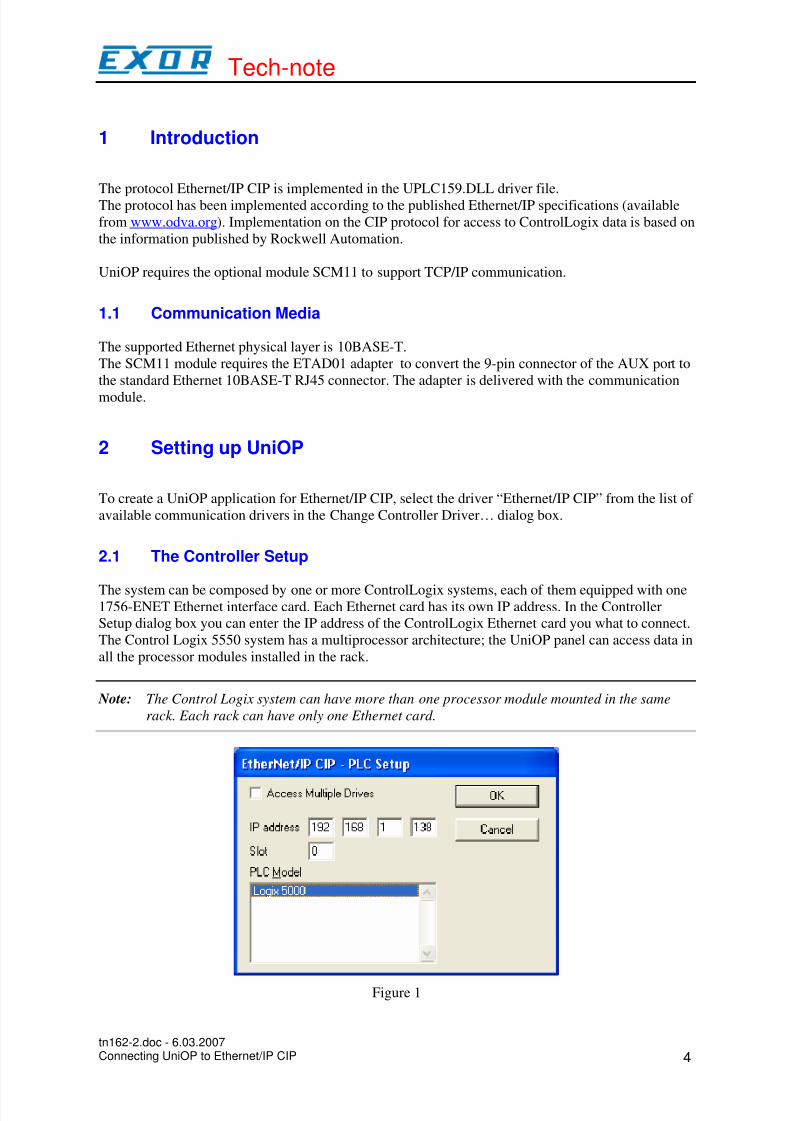
2.1 The Controller Setup
The system can be composed by one or more ControlLogix systems, each of them equipped with one1756-ENET Ethernet interface card. Each Ethernet card has its own IP address. In the Controller
Setup dialog box you can enter the IP address of the ControlLogix Ethernet card you what to connect.
The Control Logix 5550 system has a multiprocessor architecture; the UniOP panel can access data in
all the processor modules installed in the rack.
Note: The Control Logix system can have more than one processor module mounted in the same
rack. Each rack can have only one Ethernet card.
Figure 1
tn162-2.doc - 6.03.2007Connecting UniOP to Ethernet/IP CIP 4
8/8/2019 Uniop - Comunicação Ethernet
http://slidepdf.com/reader/full/uniop-comunicacao-ethernet 5/15
Tech-note
Figure 1 shows the Controller Setup dialog configured for accessing only one controller placed in the
slot 0 of the rack. The ENET card has the IP address 192.168.1.138.
2.1.1 More than one Processor in the Same Rack
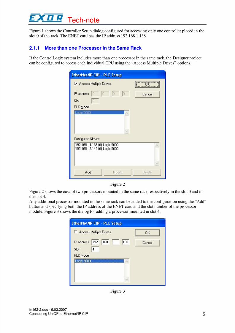
If the ControlLogix system includes more than one processor in the same rack, the Designer projectcan be configured to access each individual CPU using the “Access Multiple Drives” options.
Figure 2
Figure 2 shows the case of two processors mounted in the same rack respectively in the slot 0 and in
the slot 4.
Any additional processor mounted in the same rack can be added to the configuration using the “Add”
button and specifying both the IP address of the ENET card and the slot number of the processor
module. Figure 3 shows the dialog for adding a processor mounted in slot 4.
Figure 3
tn162-2.doc - 6.03.2007Connecting UniOP to Ethernet/IP CIP 5
8/8/2019 Uniop - Comunicação Ethernet
http://slidepdf.com/reader/full/uniop-comunicacao-ethernet 6/15
Tech-note
Note: As only one ENET card is present in the rack, the IP address is unique for all the processors
mounted in that rack.
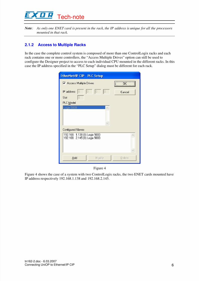
2.1.2 Access to Multiple Racks
In the case the complete control system is composed of more than one ControlLogix racks and each
rack contains one or more controllers, the “Access Multiple Drives” option can still be used to
configure the Designer project to access to each individual CPU mounted in the different racks. In this
case the IP address specified in the “PLC Setup” dialog must be different for each rack.
Figure 4
Figure 4 shows the case of a system with two ControlLogix racks, the two ENET cards mounted have
IP address respectively 192.168.1.138 and 192.168.2.145.
tn162-2.doc - 6.03.2007Connecting UniOP to Ethernet/IP CIP 6
8/8/2019 Uniop - Comunicação Ethernet
http://slidepdf.com/reader/full/uniop-comunicacao-ethernet 7/15
Tech-note
2.2 Designer Panel Setup
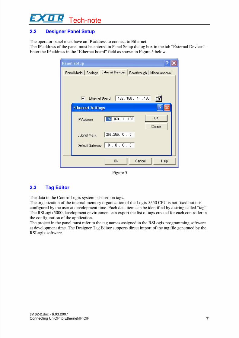
The operator panel must have an IP address to connect to Ethernet.
The IP address of the panel must be entered in Panel Setup dialog box in the tab “External Devices”.
Enter the IP address in the “Ethernet board” field as shown in Figure 5 below.
Figure 5
2.3 Tag Editor
The data in the ControlLogix system is based on tags.
The organization of the internal memory organization of the Logix 5550 CPU is not fixed but it is
configured by the user at development time. Each data item can be identified by a string called “tag”.
The RSLogix5000 development environment can export the list of tags created for each controller in
the configuration of the application.
The project in the panel must refer to the tag names assigned in the RSLogix programming software
at development time. The Designer Tag Editor supports direct import of the tag file generated by the
RSLogix software.
tn162-2.doc - 6.03.2007Connecting UniOP to Ethernet/IP CIP 7
8/8/2019 Uniop - Comunicação Ethernet
http://slidepdf.com/reader/full/uniop-comunicacao-ethernet 8/15
Tech-note
Figure 6
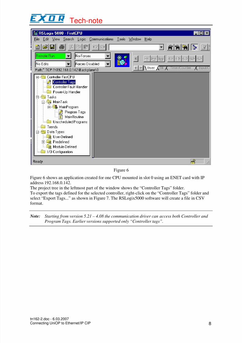
Figure 6 shows an application created for one CPU mounted in slot 0 using an ENET card with IP
address 192.168.0.142.
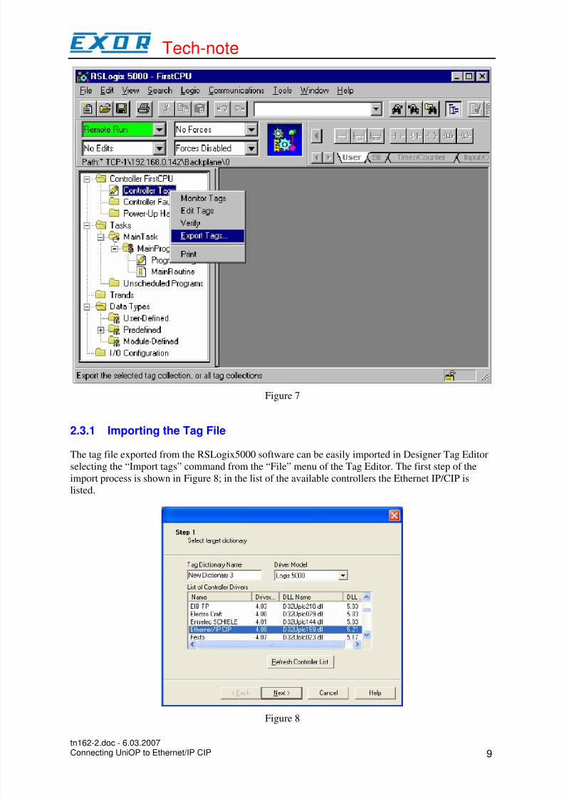
The project tree in the leftmost part of the window shows the “Controller Tags” folder.
To export the tags defined for the selected controller, right-click on the “Controller Tags” folder and
select “Export Tags...” as shown in Figure 7. The RSLogix5000 software will create a file in CSV
format.
Note: Starting from version 5.21 – 4.08 the communication driver can access both Controller and
Program Tags. Earlier versions supported only “Controller tags”.
tn162-2.doc - 6.03.2007Connecting UniOP to Ethernet/IP CIP 8
8/8/2019 Uniop - Comunicação Ethernet
http://slidepdf.com/reader/full/uniop-comunicacao-ethernet 9/15
Tech-note
Figure 7
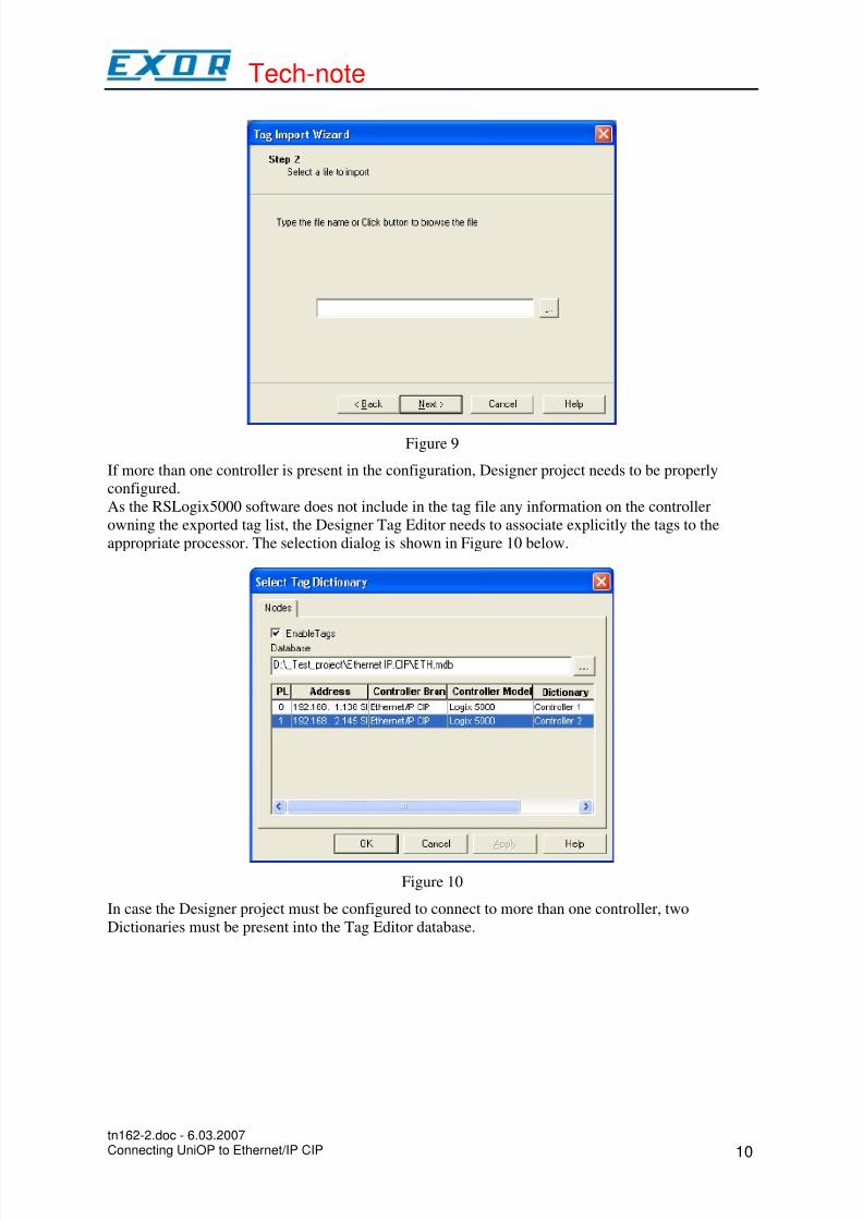
2.3.1 Importing the Tag File
The tag file exported from the RSLogix5000 software can be easily imported in Designer Tag Editor
selecting the “Import tags” command from the “File” menu of the Tag Editor. The first step of the
import process is shown in Figure 8; in the list of the available controllers the Ethernet IP/CIP is
listed.
Figure 8
tn162-2.doc - 6.03.2007Connecting UniOP to Ethernet/IP CIP 9
8/8/2019 Uniop - Comunicação Ethernet
http://slidepdf.com/reader/full/uniop-comunicacao-ethernet 10/15
Tech-note
Figure 9
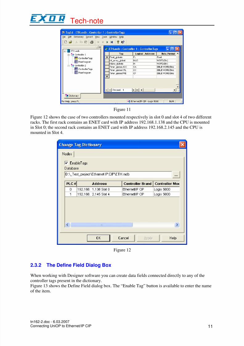
If more than one controller is present in the configuration, Designer project needs to be properly
configured.
As the RSLogix5000 software does not include in the tag file any information on the controller
owning the exported tag list, the Designer Tag Editor needs to associate explicitly the tags to the
appropriate processor. The selection dialog is shown in Figure 10 below.
Figure 10
In case the Designer project must be configured to connect to more than one controller, two
Dictionaries must be present into the Tag Editor database.
tn162-2.doc - 6.03.2007Connecting UniOP to Ethernet/IP CIP 10
8/8/2019 Uniop - Comunicação Ethernet
http://slidepdf.com/reader/full/uniop-comunicacao-ethernet 11/15
Tech-note
Figure 11
Figure 12 shows the case of two controllers mounted respectively in slot 0 and slot 4 of two different
racks. The first rack contains an ENET card with IP address 192.168.1.138 and the CPU is mountedin Slot 0; the second rack contains an ENET card with IP address 192.168.2.145 and the CPU is
mounted in Slot 4.
Figure 12
2.3.2 The Define Field Dialog Box
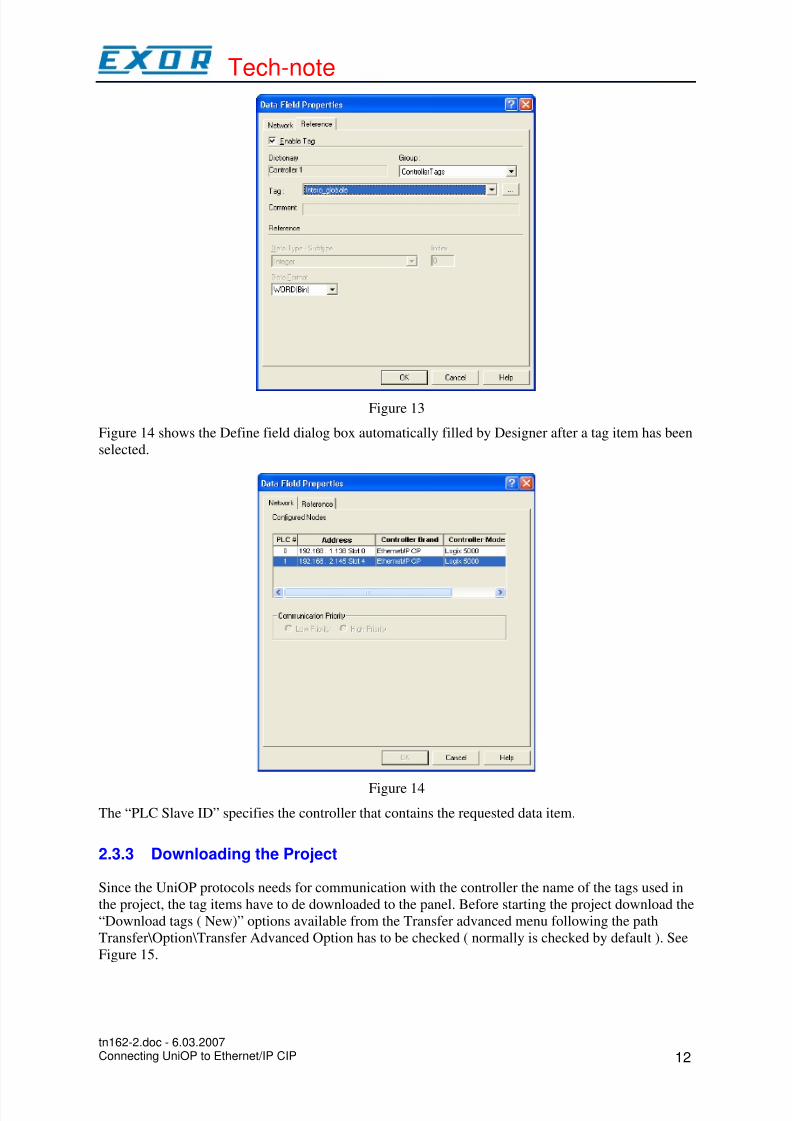
When working with Designer software you can create data fields connected directly to any of the
controller tags present in the dictionary.
Figure 13 shows the Define Field dialog box. The “Enable Tag” button is available to enter the name
of the item.
tn162-2.doc - 6.03.2007Connecting UniOP to Ethernet/IP CIP 11
8/8/2019 Uniop - Comunicação Ethernet
http://slidepdf.com/reader/full/uniop-comunicacao-ethernet 12/15
Tech-note
Figure 13
Figure 14 shows the Define field dialog box automatically filled by Designer after a tag item has been
selected.
Figure 14
The “PLC Slave ID” specifies the controller that contains the requested data item.
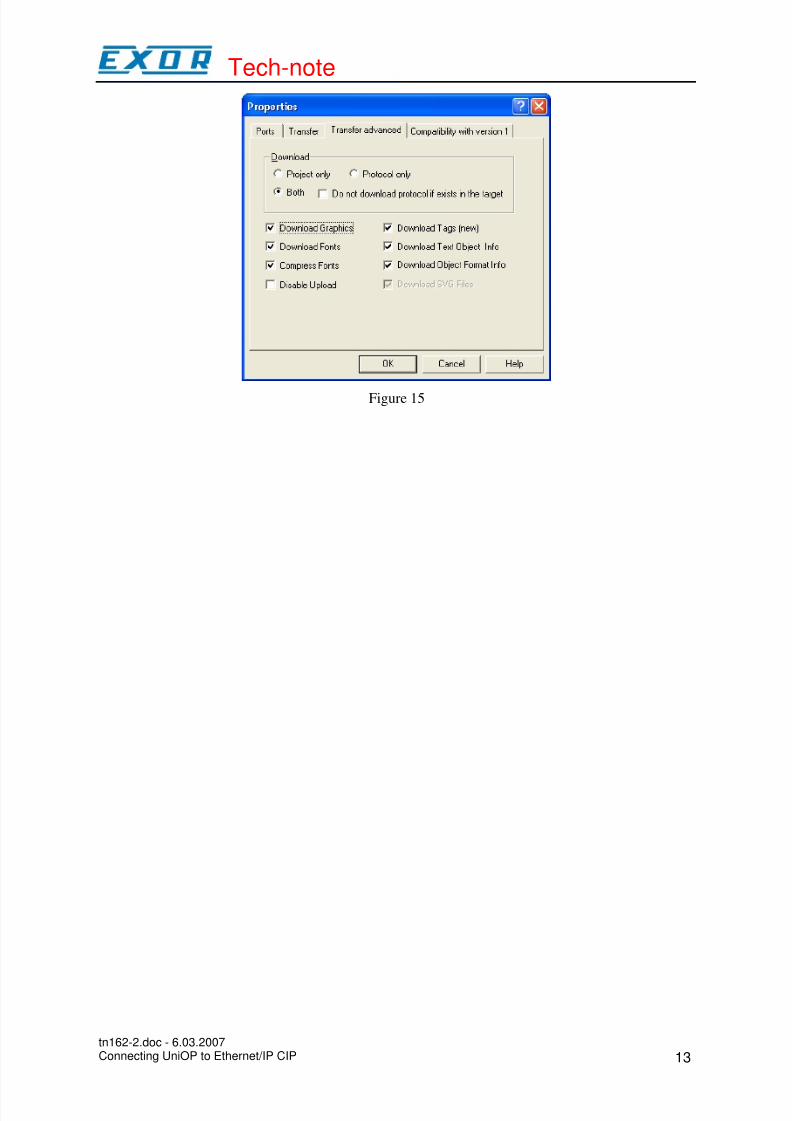
2.3.3 Downloading the Project
Since the UniOP protocols needs for communication with the controller the name of the tags used in
the project, the tag items have to de downloaded to the panel. Before starting the project download the
“Download tags ( New)” options available from the Transfer advanced menu following the path
Transfer\Option\Transfer Advanced Option has to be checked ( normally is checked by default ). See
Figure 15.
tn162-2.doc - 6.03.2007Connecting UniOP to Ethernet/IP CIP 12
8/8/2019 Uniop - Comunicação Ethernet
http://slidepdf.com/reader/full/uniop-comunicacao-ethernet 13/15
Tech-note
Figure 15
tn162-2.doc - 6.03.2007Connecting UniOP to Ethernet/IP CIP 13
8/8/2019 Uniop - Comunicação Ethernet
http://slidepdf.com/reader/full/uniop-comunicacao-ethernet 14/15
Tech-note
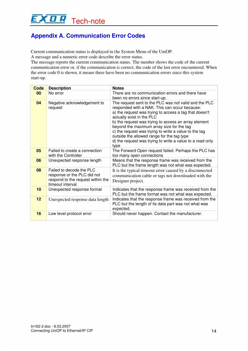
Appendix A. Communication Error Codes
Current communication status is displayed in the System Menu of the UniOP.
A message and a numeric error code describe the error status.
The message reports the current communication status. The number shows the code of the currentcommunication error or, if the communication is correct, the code of the last error encountered. When
the error code 0 is shown, it means there have been no communication errors since this system
start-up.
Code Description Notes00 No error There are no communication errors and there have
been no errors since start-up.
04 Negative acknowledgement torequest
The request sent to the PLC was not valid and the PLCresponded with a NAK. This can occur because:a) the request was trying to access a tag that doesn'tactually exist in the PLC
b) the request was trying to access an array elementbeyond the maximum array size for the tagc) the request was trying to write a value to the tagoutside the allowed range for the tag typed) the request was trying to write a value to a read onlytype
05 Failed to create a connectionwith the Controller
The Forward Open request failed. Perhaps the PLC hastoo many open connections
06 Unexpected response length Means that the response frame was received from thePLC but the frame length was not what was expected.
08 Failed to decode the PLCresponse or the PLC did notrespond to the request within the
timeout interval
It is the typical timeout error caused by a disconnected
communication cable or tags not downloaded with the
Designer project.
10 Unexpected response format Indicates that the response frame was received from thePLC but the frame format was not what was expected.
12 Unexpected response data length Indicates that the response frame was received from thePLC but the length of its data part was not what wasexpected.
16 Low level protocol error Should never happen. Contact the manufacturer.
tn162-2.doc - 6.03.2007Connecting UniOP to Ethernet/IP CIP 14
8/8/2019 Uniop - Comunicação Ethernet
http://slidepdf.com/reader/full/uniop-comunicacao-ethernet 15/15
Tech-note
Appendix B. Requirements and Compatibility
This communication driver is included in the Designer DLL file UPLC159.DLL.
The initial release level is 3.00 for the communication driver and 5.03 for the DLL (both version
numbers can be seen in the Change Controller Driver dialog box of the Designer software).
The format of the RSLogix5000 tag file is compatible with RSLogix5000 version 2.51.00 and may
not be compatible with other versions of the software.
Designer software version 5.08 or higher is required for supporting tags.
A communication module of type SCM11 is required.
The UniOP panel must have hardware type –0045 or -0050; firmware version number 4.42 or higher
is required to support operation with the SCM11 module.
Direct Access is not supported.
tn162-2.doc - 6.03.2007Connecting UniOP to Ethernet/IP CIP 15