state of the art – methods to measure moisture in concrete · fig. 1. 3d image of pore structure...
TRANSCRIPT
União Europeia – Fundos Estruturais Governo da República Portuguesa
PROJETOS DE INVESTIGAÇÃO CIENTÍFICA E DESENVOLVIMENTO TECNOLÓGICO
RELATÓRIO REFERENTE AO PROJETO PTDC/ECM/099250/2008 “Comportamento em serviço de estruturas de betão: uma abordagem multi-física das tensões
auto-induzidas”
State of the art – Methods to measure moisture in concrete
Autores: Gonzalo Quincot Miguel Azenha Joaquim Barros Rui Faria
Guimarães, UM, 2011
European Union Governo da República Portuguesa
Contents 1. Introduction ................................................................................................................................ 3
2. Methods to measure the concrete moisture .............................................................................. 6
2.1. Methods based on concentration ....................................................................................... 6
2.1.1. Gravimetric Determination ......................................................................................... 6
2.1.2. Gamma-densitometry ............................................................................................... 14
2.2. Methods based on relative humidity ................................................................................ 19
2.2.1. Relative humidity measurements embedding sensors in concrete .......................... 19
2.2.2. Resistivity .................................................................................................................. 27
2.2.3. Dielectric properties .................................................................................................. 30
2.2.4. Thermal properties .................................................................................................... 32
2.2.5. Infrared Adsorption ................................................................................................... 32
2.2.6. Neutron scattering .................................................................................................... 33
2.2.7. Nanotechnology/Microelectromechanical systems sensors .................................... 34
European Union Governo da República Portuguesa
The objective of this document is to do an overview of the existing measuring methods to
determine the moisture profile inside the concrete and asses their relative performance.
1. Introduction
The concrete is composed by graded fine and coarse aggregates, sand, cement, water and pores.
Water in concrete exist as chemically bounded, which is the water that reacts with the cement
particles and is responsible of the hydration of cement; and physically bounded, which is the water
that did not react with cement and gives rise to capillary porosity. The pores can have water vapor
inside with absorbed water on the walls, water vapor and liquid water on the walls and be fully
saturated with water. All these states are water physically bound to concrete. These distinct states
of water can be lost by being exposed to the environment or can be evaporable when oven drying
at 105°C. The rest of the water belongs to the cement paste, where besides water chemically
bounded, the physically bounded water exist but is so strongly bound that just evaporates at
temperatures up to 500 °C. To determine moisture profiles in concrete is necessary to measure its
evaporable water or water physically bounded.
The moisture can be regarded in the following two main categories in concrete: As a concentration
(mass per volume) and as pore relative humidity. Both categories are related by moisture
isotherms.
The concrete pore structure influences its physical properties, particularly in terms of permeability
and strength. Regarding the permeability the pore network should also be considered. The pore
network can be measured by mercury intrusion porosimetry (MIP), but this technique cannot
indicate the pore shape or the position of the pores, which are important information to analyze the
pore connectivity. On this regard, Kurimisawa et al. (2006) developed a technique for the
visualization of the pore structure. In this technique the mercury is substituted for gallium. Gallium
intruded into the pores is observed in the solid phase by electron probe micro analysis (EPMA).
Several observations by EPMA were performed and three-dimensional images of the pore structure
were reconstructed by stacking the acquired images of the pore structure. This experiment
technique was done to clarify the relationship between water permeability and pore connectivity
(Kurumisawa and Tanaka 2006).
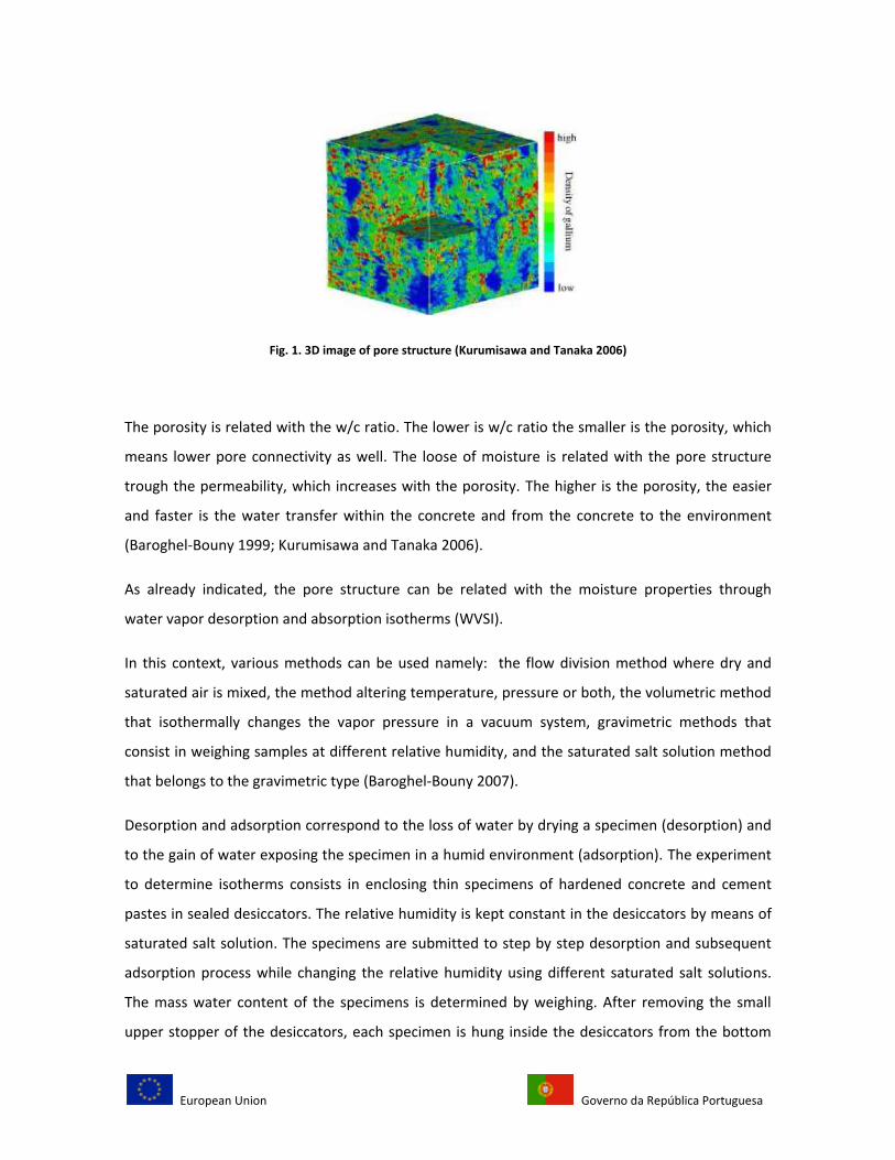
Figure 1 shows a 3D image of a pore structure in a hardened cement paste. In this color
representation, red indicates a high concentration of gallium, while blue means zones of reduced
percentage of gallium. Hence, the pixels in blue show the solid phase. The highest concentration of
gallium represents a pore of 1µm2.
European Union Governo da República Portuguesa
Fig. 1. 3D image of pore structure (Kurumisawa and Tanaka 2006)
The porosity is related with the w/c ratio. The lower is w/c ratio the smaller is the porosity, which
means lower pore connectivity as well. The loose of moisture is related with the pore structure
trough the permeability, which increases with the porosity. The higher is the porosity, the easier
and faster is the water transfer within the concrete and from the concrete to the environment
(Baroghel-Bouny 1999; Kurumisawa and Tanaka 2006).
As already indicated, the pore structure can be related with the moisture properties through
water vapor desorption and absorption isotherms (WVSI).
In this context, various methods can be used namely: the flow division method where dry and
saturated air is mixed, the method altering temperature, pressure or both, the volumetric method
that isothermally changes the vapor pressure in a vacuum system, gravimetric methods that
consist in weighing samples at different relative humidity, and the saturated salt solution method
that belongs to the gravimetric type (Baroghel-Bouny 2007).
Desorption and adsorption correspond to the loss of water by drying a specimen (desorption) and
to the gain of water exposing the specimen in a humid environment (adsorption). The experiment
to determine isotherms consists in enclosing thin specimens of hardened concrete and cement
pastes in sealed desiccators. The relative humidity is kept constant in the desiccators by means of
saturated salt solution. The specimens are submitted to step by step desorption and subsequent
adsorption process while changing the relative humidity using different saturated salt solutions.
The mass water content of the specimens is determined by weighing. After removing the small
upper stopper of the desiccators, each specimen is hung inside the desiccators from the bottom
European Union Governo da República Portuguesa
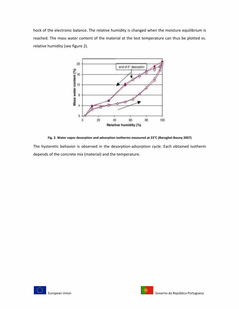
hock of the electronic balance. The relative humidity is changed when the moisture equilibrium is
reached. The mass water content of the material at the test temperature can thus be plotted vs.
relative humidity (see figure 2).
Fig. 2. Water vapor desorption and adsorption isotherms measured at 23°C (Baroghel-Bouny 2007)
The hysteretic behavior is observed in the desorption-adsorption cycle. Each obtained isotherm
depends of the concrete mix (material) and the temperature.
European Union Governo da República Portuguesa
2. Methods to measure the concrete moisture
Water in concrete is presented in three states: as free water held by capillarity, as absorbed water
held by surfaces forces and as bound water held chemically. The ideal method of moisture
measurement should quantify amounts of these three states but this is a difficult task because
moisture in concrete is not uniformly distributed, and moisture distribution varies with the
exposure time (Li Chunqiu 2008). Temperature, wind speed and environmental relative humidity
are variables that must be considered at the moment of this measurement as well.
Most methods for determining moisture diffusivity are based on the analysis of the change of
moisture profiles along time. For this analysis, a sufficient number of measured points forming the
moisture profile is necessary (J. Drchalová 2003)
The following methods show how to monitor the moisture content in concrete.
2.1. Methods based on concentration
2.1.1. Gravimetric Determination
Gravimetric methods consist on determining water content through weighting samples upon oven
drying, encompassing absorbed and chemically bound water. There are automatic moisture
analyzers that utilize infrared lamps as a heat resource as well. This technique measures the
weight loss of hardened concrete slices or specific portions, by comparing to the original weight of
the sample, and then the lost of water can be determined. The results may be expressed by
weight as the difference of the mass of water present to the dry weight of the concrete sample or
by volume as difference of the volume of water to the total volume of the concrete sample
(DeAngelis 2007). This method is considered to be the most direct and reliable procedure despite
the large number of specimens it is required, since different samples should be used for each
measure, and only the average water content of each portion or slice should be obtained. It is also
one of the few methods that can be employed at high moisture contents (Jana Selih 1996).
H. Akita et al. 1996, proposed the analysis of prismatic concrete specimens in order to quantify the
moisture transfer experimentally and numerically. Variations in water content were measured at
European Union Governo da República Portuguesa
different depths by splitting the specimens and comparing the mass of each peace before and
after oven drying at 105°C. The numerical method was made by calculating a diffusion coefficient,
whose explanation is not provided at the present stage, and can be considered as another indirect
method to determine moisture inside concrete.
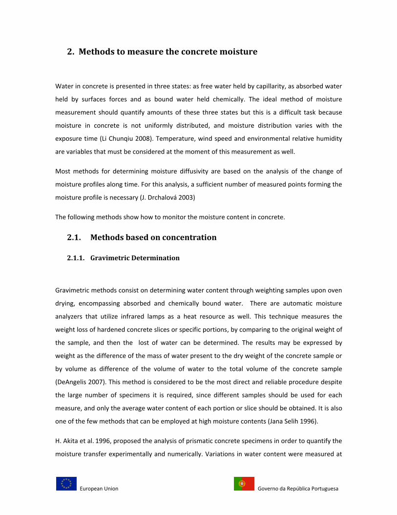
In Akita´s experiment, the specimens were prepared using normal Portland cement, river
aggregate (maximum size 20mm) and river sand, with a size of 10x10x40 cm and notched in
preparation for splitting as shown in figure 3. The specimens were cured for 28 days and after
that, the environmental conditions were maintained at 20°C and 60% relative humidity.
Fig. 3. Dimension (mm) of specimens subjected to one-face drying (Akita and : 1996).
Four experiments were performed. In the first, one-face drying was performed in order to observe
the water content profiles relative to one direction moisture transfer. The second also involved
one-face drying in order to observe the decrease in mass of specimens and to evaluate the surface
factors related to water diffusion for different concrete mix proportions, such as water/cement
ratio, mass decrease and mass of water for the specimen. The third experiment involved six-face
drying in order to observe the decrease in mass of the specimens as well, but in a wide range of
mix proportions and finally, the fourth experiment has the purpose to measure the equilibrium
water content at various levels of atmospheric humidity, which means measure the water content
when the specimen gets its equilibrium with the environmental RH (Akita and : 1996).
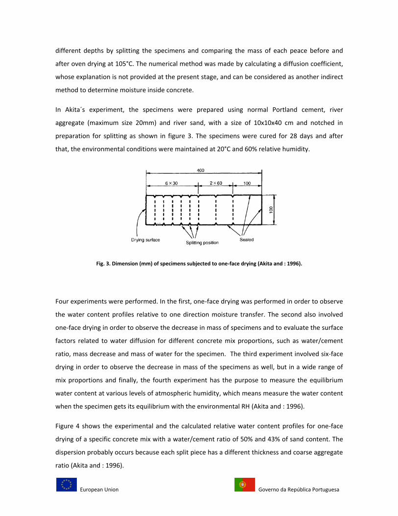
Figure 4 shows the experimental and the calculated relative water content profiles for one-face
drying of a specific concrete mix with a water/cement ratio of 50% and 43% of sand content. The
dispersion probably occurs because each split piece has a different thickness and coarse aggregate
ratio (Akita and : 1996).
European Union Governo da República Portuguesa
Fig. 4. Profiles of relative water content for one-face drying, where X represent the specimen depth in cm (Akita and :
1996)
J. Selih (1996), used a modified gravimetric method to obtain the local moisture content regarding
the redistribution of moisture after sealing the drying surface. On his experimental program,
measurements of moisture content were performed on normal and lightweight concrete cylinders
with length of 100mm, 150mm and 200mm, and diameter of 100mm, water/cement ratio of 40%
and 60% (normal Portland cement), 34% of coarse aggregates, and 31% and 36% of fine
aggregates of the fresh concrete volume. The maximum size of the coarse aggregate is 12.5mm.
The cylinders were cast into plastic moulds and covered with a plastic sheet for 12 hours to
prevent water evaporation from unhardened concrete. After this, the cylinders were placed in the
moist curing room with relative humidity within 95% to 100%. Moist curing time varied from 0 to
28 days, and when the pre-specified moist curing period has elapsed, the cylinders were exposed
to drying on the top surface at constant temperature of 22 +- 1°C and relative humidity of 50+-5%.
Zero days moist concrete (specimens which were not cured) was exposed to drying immediately
after removing the plastic sheet.
Then cylinders are placed vertically with the drying surface on the top. The moulds were not
removed during drying neither during moist curing. On this way, the side and surface of the
European Union Governo da República Portuguesa
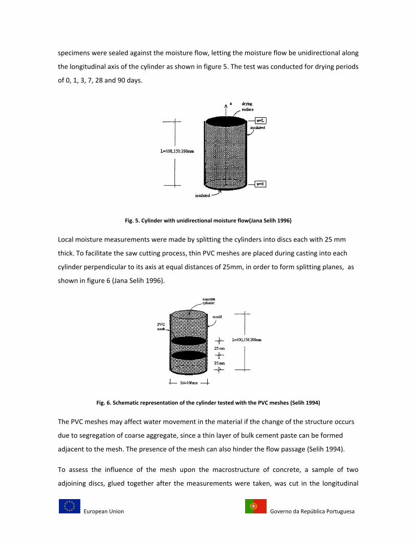
specimens were sealed against the moisture flow, letting the moisture flow be unidirectional along
the longitudinal axis of the cylinder as shown in figure 5. The test was conducted for drying periods
of 0, 1, 3, 7, 28 and 90 days.
Fig. 5. Cylinder with unidirectional moisture flow(Jana Selih 1996)
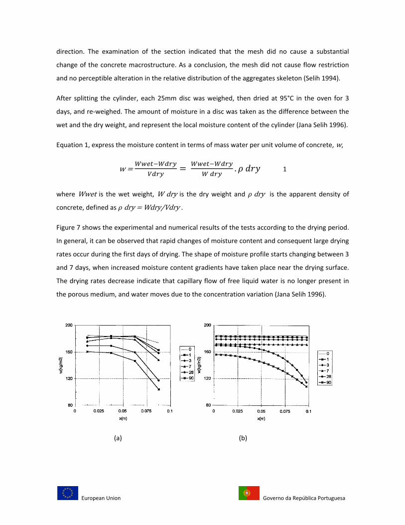
Local moisture measurements were made by splitting the cylinders into discs each with 25 mm
thick. To facilitate the saw cutting process, thin PVC meshes are placed during casting into each
cylinder perpendicular to its axis at equal distances of 25mm, in order to form splitting planes, as
shown in figure 6 (Jana Selih 1996).
Fig. 6. Schematic representation of the cylinder tested with the PVC meshes (Selih 1994)
The PVC meshes may affect water movement in the material if the change of the structure occurs
due to segregation of coarse aggregate, since a thin layer of bulk cement paste can be formed
adjacent to the mesh. The presence of the mesh can also hinder the flow passage (Selih 1994).
To assess the influence of the mesh upon the macrostructure of concrete, a sample of two
adjoining discs, glued together after the measurements were taken, was cut in the longitudinal
European Union Governo da República Portuguesa
direction. The examination of the section indicated that the mesh did no cause a substantial
change of the concrete macrostructure. As a conclusion, the mesh did not cause flow restriction
and no perceptible alteration in the relative distribution of the aggregates skeleton (Selih 1994).
After splitting the cylinder, each 25mm disc was weighed, then dried at 95°C in the oven for 3
days, and re-weighed. The amount of moisture in a disc was taken as the difference between the
wet and the dry weight, and represent the local moisture content of the cylinder (Jana Selih 1996).
Equation 1, express the moisture content in terms of mass water per unit volume of concrete, w,
w = 1
where Wwet is the wet weight, W dry is the dry weight and dry is the apparent density of
concrete, defined as dry = Wdry/Vdry .
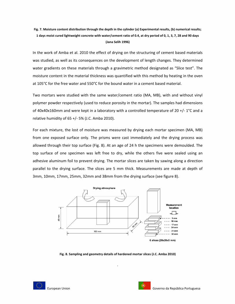
Figure 7 shows the experimental and numerical results of the tests according to the drying period.
In general, it can be observed that rapid changes of moisture content and consequent large drying
rates occur during the first days of drying. The shape of moisture profile starts changing between 3
and 7 days, when increased moisture content gradients have taken place near the drying surface.
The drying rates decrease indicate that capillary flow of free liquid water is no longer present in
the porous medium, and water moves due to the concentration variation (Jana Selih 1996).
(a) (b)
European Union Governo da República Portuguesa
Fig. 7. Moisture content distribution through the depth in the cylinder (a) Experimental results, (b) numerical results;
1 days moist cured lightweight concrete with water/cement ratio of 0.4, at dry period of 0, 1, 3, 7, 28 and 90 days
(Jana Selih 1996)
In the work of Amba et al. 2010 the effect of drying on the structuring of cement based materials
was studied, as well as its consequences on the development of length changes. They determined
water gradients on these materials through a gravimetric method designated as “Slice test”. The
moisture content in the material thickness was quantified with this method by heating in the oven
at 105°C for the free water and 550°C for the bound water in a cement based material.
Two mortars were studied with the same water/cement ratio (MA, MB), with and without vinyl
polymer powder respectively (used to reduce porosity in the mortar). The samples had dimensions
of 40x40x160mm and were kept in a laboratory with a controlled temperature of 20 +/- 1°C and a
relative humidity of 65 +/- 5% (J.C. Amba 2010).
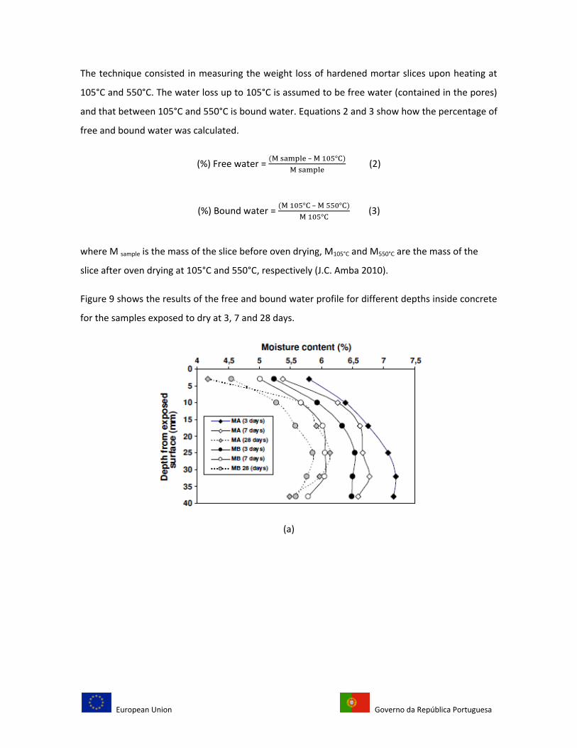
For each mixture, the lost of moisture was measured by drying each mortar specimen (MA, MB)
from one exposed surface only. The prisms were cast immediately and the drying process was
allowed through their top surface (Fig. 8). At an age of 24 h the specimens were demoulded. The
top surface of one specimen was left free to dry, while the others five were sealed using an
adhesive aluminum foil to prevent drying. The mortar slices are taken by sawing along a direction
parallel to the drying surface. The slices are 5 mm thick. Measurements are made at depth of
3mm, 10mm, 17mm, 25mm, 32mm and 38mm from the drying surface (see figure 8).
Fig. 8. Sampling and geometry details of hardened mortar slices (J.C. Amba 2010)
.
European Union Governo da República Portuguesa
The technique consisted in measuring the weight loss of hardened mortar slices upon heating at
105°C and 550°C. The water loss up to 105°C is assumed to be free water (contained in the pores)
and that between 105°C and 550°C is bound water. Equations 2 and 3 show how the percentage of
free and bound water was calculated.
(%) Free water = –
(2)
(%) Bound water = –
(3)
where M sample is the mass of the slice before oven drying, M105°C and M550°C are the mass of the
slice after oven drying at 105°C and 550°C, respectively (J.C. Amba 2010).
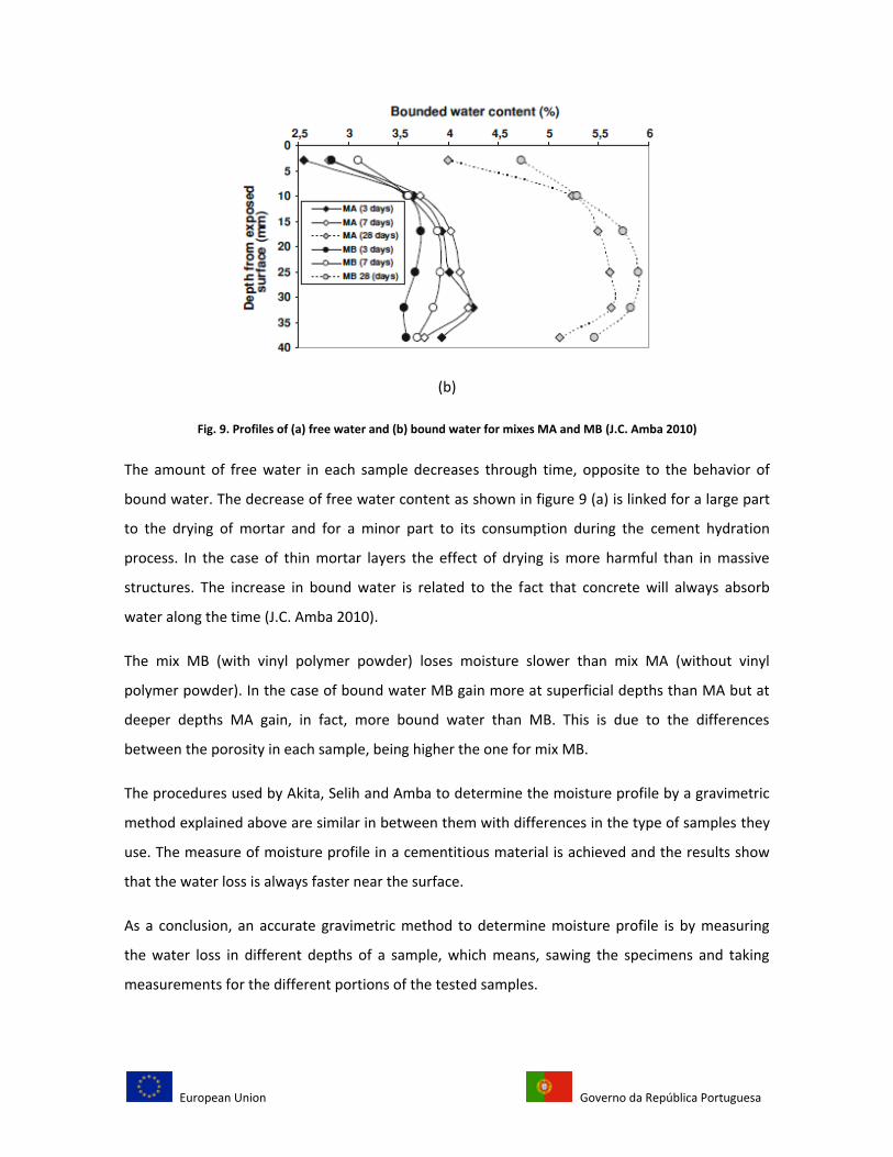
Figure 9 shows the results of the free and bound water profile for different depths inside concrete
for the samples exposed to dry at 3, 7 and 28 days.
(a)
European Union Governo da República Portuguesa
(b)
Fig. 9. Profiles of (a) free water and (b) bound water for mixes MA and MB (J.C. Amba 2010)
The amount of free water in each sample decreases through time, opposite to the behavior of
bound water. The decrease of free water content as shown in figure 9 (a) is linked for a large part
to the drying of mortar and for a minor part to its consumption during the cement hydration
process. In the case of thin mortar layers the effect of drying is more harmful than in massive
structures. The increase in bound water is related to the fact that concrete will always absorb
water along the time (J.C. Amba 2010).
The mix MB (with vinyl polymer powder) loses moisture slower than mix MA (without vinyl
polymer powder). In the case of bound water MB gain more at superficial depths than MA but at
deeper depths MA gain, in fact, more bound water than MB. This is due to the differences
between the porosity in each sample, being higher the one for mix MB.
The procedures used by Akita, Selih and Amba to determine the moisture profile by a gravimetric
method explained above are similar in between them with differences in the type of samples they
use. The measure of moisture profile in a cementitious material is achieved and the results show
that the water loss is always faster near the surface.
As a conclusion, an accurate gravimetric method to determine moisture profile is by measuring
the water loss in different depths of a sample, which means, sawing the specimens and taking
measurements for the different portions of the tested samples.
European Union Governo da República Portuguesa
2.1.2. Gamma-densitometry
The gamma densitometry is a nondestructive testing method commonly used to control the
density of civil engineering materials (Villain and Thiery 2006).
In concrete durability research, profiles of density variation are of great interest. Certain concrete
properties to transfer corrosive agents or the exchanging with the environment which can affect
the internal structure of concrete elements are strongly influenced by the concrete water content.
Since it is difficult to dry quickly, correctly and homogeneously a concrete sample, a non-
destructive testing method is necessary to obtain the profiles of water content, in order to control
the water content of the material and the moisture gradients between the core and the
surface(Villain and Thiery 2006).
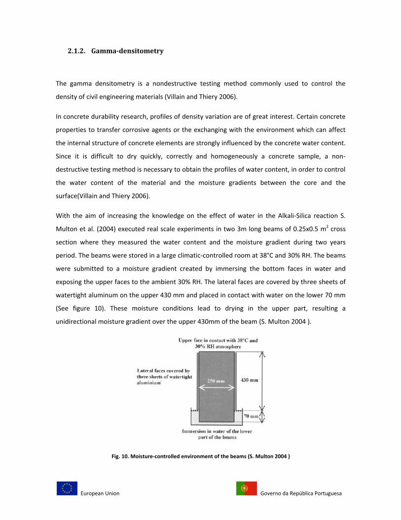
With the aim of increasing the knowledge on the effect of water in the Alkali-Silica reaction S.
Multon et al. (2004) executed real scale experiments in two 3m long beams of 0.25x0.5 m2 cross
section where they measured the water content and the moisture gradient during two years
period. The beams were stored in a large climatic-controlled room at 38°C and 30% RH. The beams
were submitted to a moisture gradient created by immersing the bottom faces in water and
exposing the upper faces to the ambient 30% RH. The lateral faces are covered by three sheets of
watertight aluminum on the upper 430 mm and placed in contact with water on the lower 70 mm
(See figure 10). These moisture conditions lead to drying in the upper part, resulting a
unidirectional moisture gradient over the upper 430mm of the beam (S. Multon 2004 ).
Fig. 10. Moisture-controlled environment of the beams (S. Multon 2004 )
European Union Governo da República Portuguesa
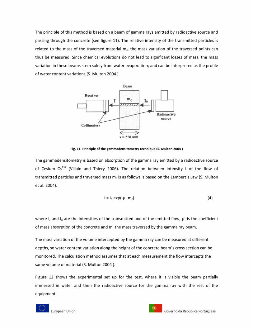
The principle of this method is based on a beam of gamma rays emitted by radioactive source and
passing through the concrete (see figure 11). The relative intensity of the transmitted particles is
related to the mass of the traversed material mc, the mass variation of the traversed points can
thus be measured. Since chemical evolutions do not lead to significant losses of mass, the mass
variation in these beams stem solely from water evaporation; and can be interpreted as the profile
of water content variations (S. Multon 2004 ).
Fig. 11. Principle of the gammadensitometry technique (S. Multon 2004 )
The gammadensitometry is based on absorption of the gamma ray emitted by a radioactive source
of Cesium Cs137 (Villain and Thiery 2006). The relation between intensity I of the flow of
transmitted particles and traversed mass mc is as follows is based on the Lambert´s Law (S. Multon
et al. 2004):
I = Io.exp(-µ´.mc) (4)
where I, and Io are the intensities of the transmitted and of the emitted flow, µ´ is the coefficient
of mass absorption of the concrete and mc the mass traversed by the gamma ray beam.
The mass variation of the volume intercepted by the gamma ray can be measured at different
depths, so water content variation along the height of the concrete beam´s cross section can be
monitored. The calculation method assumes that at each measurement the flow intercepts the
same volume of material (S. Multon 2004 ).
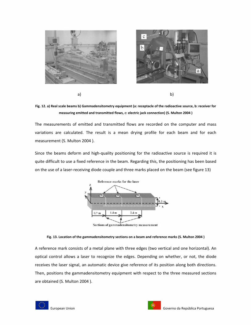
Figure 12 shows the experimental set up for the test, where it is visible the beam partially
immersed in water and then the radioactive source for the gamma ray with the rest of the
equipment.
European Union Governo da República Portuguesa
a) b)
Fig. 12. a) Real scale beams b) Gammadensitometry equipment (a: receptacle of the radioactive source, b: receiver for
measuring emitted and transmitted flows, c: electric jack connection) (S. Multon 2004 )
The measurements of emitted and transmitted flows are recorded on the computer and mass
variations are calculated. The result is a mean drying profile for each beam and for each
measurement (S. Multon 2004 ).
Since the beams deform and high-quality positioning for the radioactive source is required it is
quite difficult to use a fixed reference in the beam. Regarding this, the positioning has been based
on the use of a laser-receiving diode couple and three marks placed on the beam (see figure 13)
Fig. 13. Location of the gammadensitometry sections on a beam and reference marks (S. Multon 2004 )
A reference mark consists of a metal plane with three edges (two vertical and one horizontal). An
optical control allows a laser to recognize the edges. Depending on whether, or not, the diode
receives the laser signal, an automatic device give reference of its position along both directions.
Then, positions the gammadensitometry equipment with respect to the three measured sections
are obtained (S. Multon 2004 ).
European Union Governo da República Portuguesa
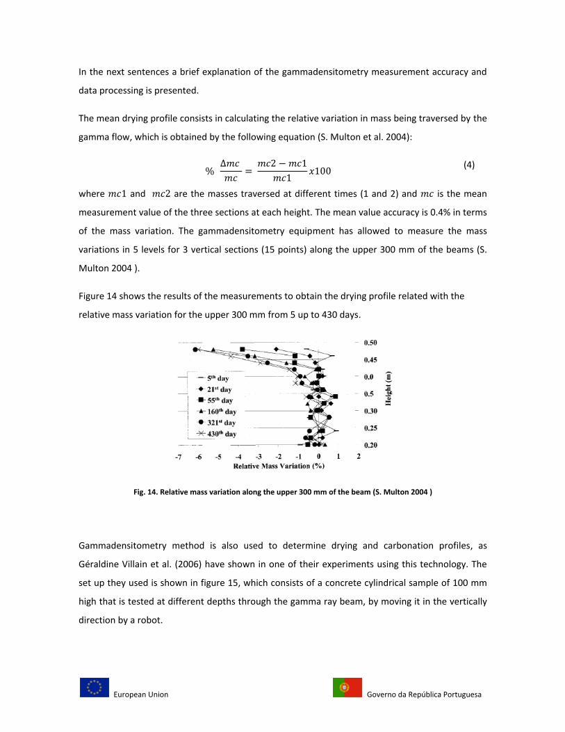
In the next sentences a brief explanation of the gammadensitometry measurement accuracy and
data processing is presented.
The mean drying profile consists in calculating the relative variation in mass being traversed by the
gamma flow, which is obtained by the following equation (S. Multon et al. 2004):
(4)
where and are the masses traversed at different times (1 and 2) and is the mean
measurement value of the three sections at each height. The mean value accuracy is 0.4% in terms
of the mass variation. The gammadensitometry equipment has allowed to measure the mass
variations in 5 levels for 3 vertical sections (15 points) along the upper 300 mm of the beams (S.
Multon 2004 ).
Figure 14 shows the results of the measurements to obtain the drying profile related with the
relative mass variation for the upper 300 mm from 5 up to 430 days.
Fig. 14. Relative mass variation along the upper 300 mm of the beam (S. Multon 2004 )
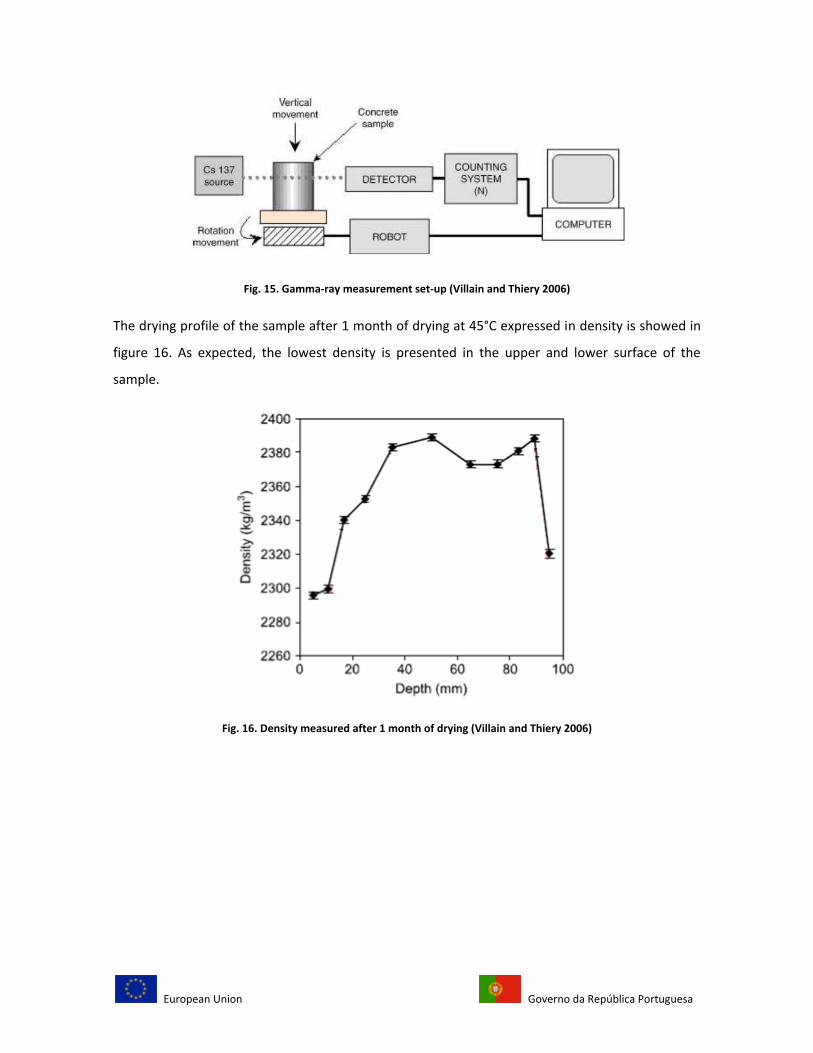
Gammadensitometry method is also used to determine drying and carbonation profiles, as
Géraldine Villain et al. (2006) have shown in one of their experiments using this technology. The
set up they used is shown in figure 15, which consists of a concrete cylindrical sample of 100 mm
high that is tested at different depths through the gamma ray beam, by moving it in the vertically
direction by a robot.
European Union Governo da República Portuguesa
Fig. 15. Gamma-ray measurement set-up (Villain and Thiery 2006)
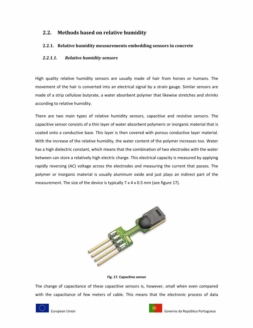
The drying profile of the sample after 1 month of drying at 45°C expressed in density is showed in
figure 16. As expected, the lowest density is presented in the upper and lower surface of the
sample.
Fig. 16. Density measured after 1 month of drying (Villain and Thiery 2006)
European Union Governo da República Portuguesa
2.2. Methods based on relative humidity
2.2.1. Relative humidity measurements embedding sensors in concrete
2.2.1.1. Relative humidity sensors
High quality relative humidity sensors are usually made of hair from horses or humans. The
movement of the hair is converted into an electrical signal by a strain gauge. Similar sensors are
made of a strip cellulose butyrate, a water absorbent polymer that likewise stretches and shrinks
according to relative humidity.
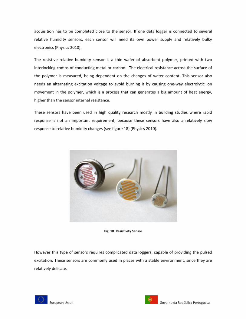
There are two main types of relative humidity sensors, capacitive and resistive sensors. The
capacitive sensor consists of a thin layer of water absorbent polymeric or inorganic material that is
coated onto a conductive base. This layer is then covered with porous conductive layer material.
With the increase of the relative humidity, the water content of the polymer increases too. Water
has a high dielectric constant, which means that the combination of two electrodes with the water
between can store a relatively high electric charge. This electrical capacity is measured by applying
rapidly reversing (AC) voltage across the electrodes and measuring the current that passes. The
polymer or inorganic material is usually aluminum oxide and just plays an indirect part of the
measurement. The size of the device is typically 7 x 4 x 0.5 mm (see figure 17).
Fig. 17. Capacitive sensor
The change of capacitance of these capacitive sensors is, however, small when even compared
with the capacitance of few meters of cable. This means that the electronic process of data
European Union Governo da República Portuguesa
acquisition has to be completed close to the sensor. If one data logger is connected to several
relative humidity sensors, each sensor will need its own power supply and relatively bulky
electronics (Physics 2010).
The resistive relative humidity sensor is a thin wafer of absorbent polymer, printed with two
interlocking combs of conducting metal or carbon. The electrical resistance across the surface of
the polymer is measured, being dependent on the changes of water content. This sensor also
needs an alternating excitation voltage to avoid burning it by causing one-way electrolytic ion
movement in the polymer, which is a process that can generates a big amount of heat energy,
higher than the sensor internal resistance.
These sensors have been used in high quality research mostly in building studies where rapid
response is not an important requirement, because these sensors have also a relatively slow
response to relative humidity changes (see figure 18) (Physics 2010).
Fig. 18. Resistivity Sensor
However this type of sensors requires complicated data loggers, capable of providing the pulsed
excitation. These sensors are commonly used in places with a stable environment, since they are
relatively delicate.
European Union Governo da República Portuguesa
In fact relative humidity sensors are easily contaminated by water soluble salts. The sensor can be
protected with Gore-Tex® or with a thin layer of silicone (less than 0.5 mm). These materials allow
the water molecules to flow and offer resistance to ions penetration that can influence the
behavior of the sensor. However, the envelope formed by this thin layer should not touch the
sensor surface. These kinds of semi-permeable membranes will lengthen the time response for
changes in relative humidity of the thin film sensors from about a minute to twenty minutes
(Physics 2010). Due to these reasons, this sensor has dropped out of fashion.
2.2.1.2. Techniques for relative humidity measurements inside concrete
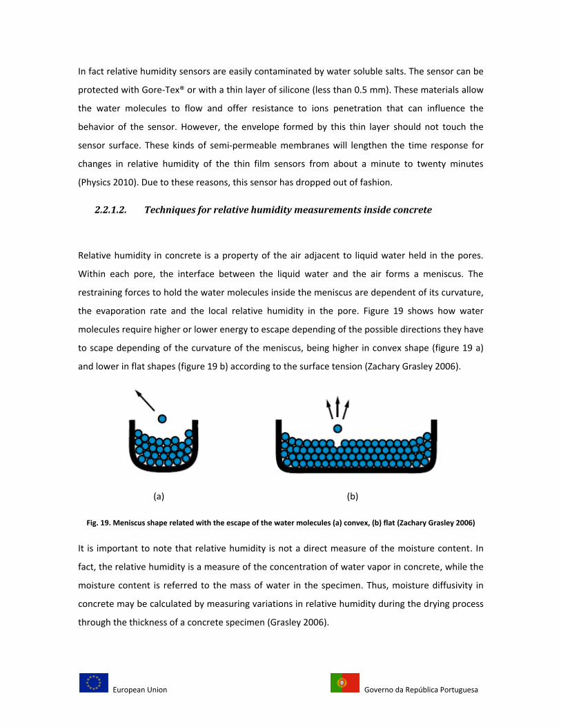
Relative humidity in concrete is a property of the air adjacent to liquid water held in the pores.
Within each pore, the interface between the liquid water and the air forms a meniscus. The
restraining forces to hold the water molecules inside the meniscus are dependent of its curvature,
the evaporation rate and the local relative humidity in the pore. Figure 19 shows how water
molecules require higher or lower energy to escape depending of the possible directions they have
to scape depending of the curvature of the meniscus, being higher in convex shape (figure 19 a)
and lower in flat shapes (figure 19 b) according to the surface tension (Zachary Grasley 2006).
(a) (b)
Fig. 19. Meniscus shape related with the escape of the water molecules (a) convex, (b) flat (Zachary Grasley 2006)
It is important to note that relative humidity is not a direct measure of the moisture content. In
fact, the relative humidity is a measure of the concentration of water vapor in concrete, while the
moisture content is referred to the mass of water in the specimen. Thus, moisture diffusivity in
concrete may be calculated by measuring variations in relative humidity during the drying process
through the thickness of a concrete specimen (Grasley 2006).
European Union Governo da República Portuguesa
The sensing element of a relative humidity probe is generally a hygroscopic material in which
length, resistance or capacitance changes are detected. Such probes are commercially available
and are small enough to be used for measuring relative humidity gradients inside concrete (Parrott
1990). There are other types of relative humidity sensors with different measuring principles, such
as chilled mirror or magnetic waves, but are relatively expensive and their large size does not
allow measurements at precise locations, which is necessary to determine a water content profile
inside concrete specimens. A list of relative humidity sensors will be presented later in this
document.
Using capacitive sensors, Z. Grasley et al. 2002 measured the relative humidity, at an age of 1 day,
in concrete specimens with water/cement ratio 0.44 after two sides of the specimens have been
exposed to 50% RH ambient conditions. Although capacitive sensors can have reduced accuracy at
relative humidity values exceeding 90%, they typically provide better linearity than resistive
sensors. However, capacitive sensors can take several hours to reach equilibrium and provide valid
readings (Wiederhold 1997). They cannot also be directly exposed to fresh concrete. To solve this
problem in the experiment, the sensors are mounted in plastic tubes with Gore-tex® caps and then
embedded in fresh concrete. This material, protect the sensor from liquid water but allows vapor
transmission. The vapor pressure within the airspace around the sensor and in the concrete pores
will always be equal. This allowed the sensor to be permanently embedded in the concrete
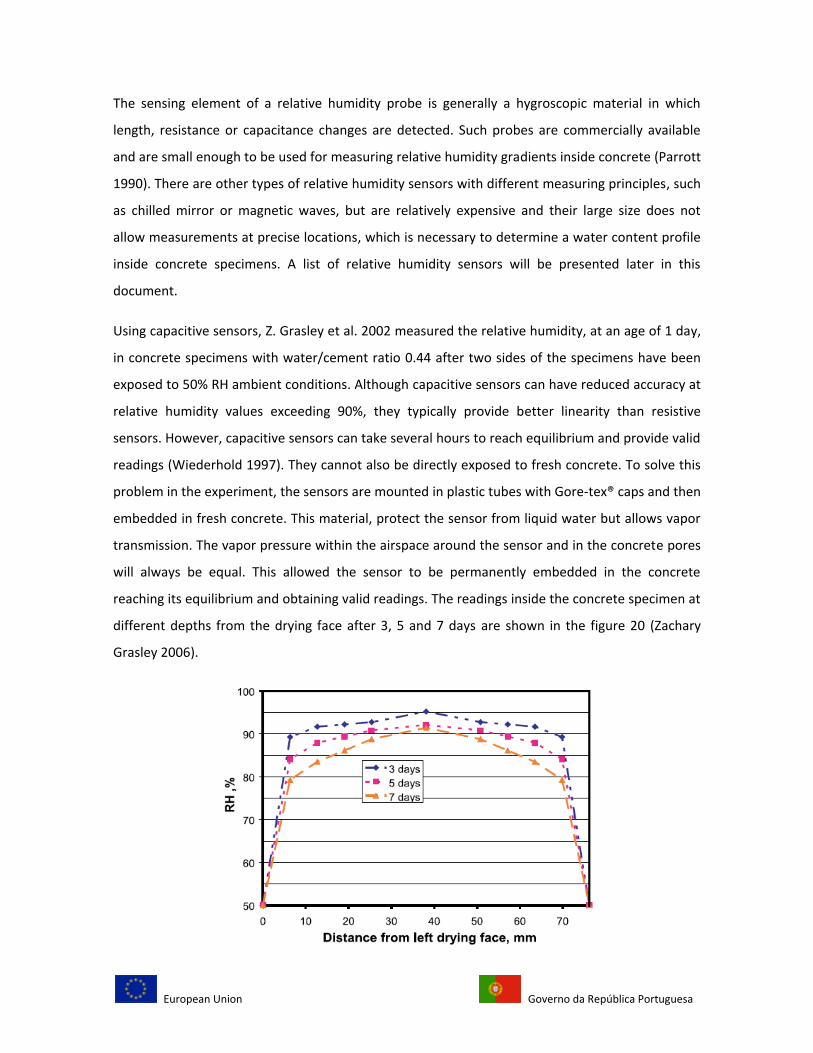
reaching its equilibrium and obtaining valid readings. The readings inside the concrete specimen at
different depths from the drying face after 3, 5 and 7 days are shown in the figure 20 (Zachary
Grasley 2006).
European Union Governo da República Portuguesa
Fig. 20. Evolution of relative humidity in a concrete specimen (Zachary Grasley 2006)
As in the gravimetric method, the moisture profile has the same shape through the depth of the
specimen.
To embed the sensors inside concrete, it is important to make a difference between installing the
tubes in the mould before cast (without drilling) and drilling holes in a hardened concrete to
embed the sensors after, as it has been mentioned in L.J. Parrot document. The drilling process
affects the local water content in the specimen.
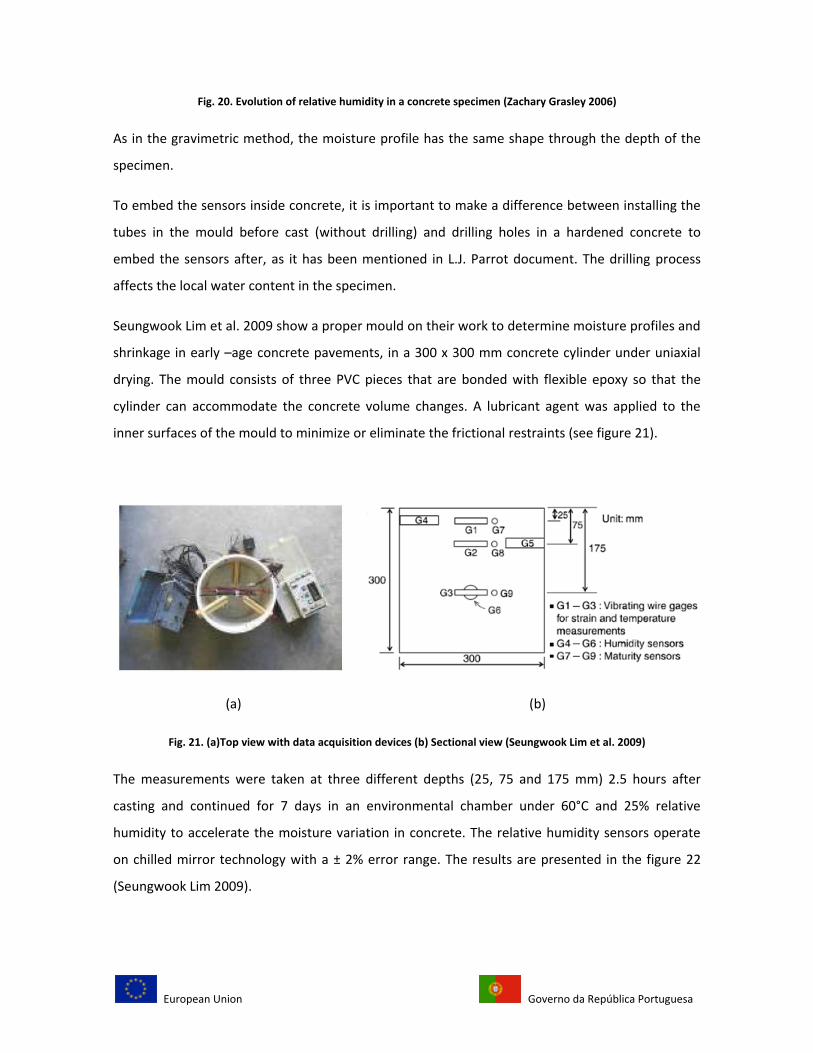
Seungwook Lim et al. 2009 show a proper mould on their work to determine moisture profiles and
shrinkage in early –age concrete pavements, in a 300 x 300 mm concrete cylinder under uniaxial
drying. The mould consists of three PVC pieces that are bonded with flexible epoxy so that the
cylinder can accommodate the concrete volume changes. A lubricant agent was applied to the
inner surfaces of the mould to minimize or eliminate the frictional restraints (see figure 21).
(a) (b)
Fig. 21. (a)Top view with data acquisition devices (b) Sectional view (Seungwook Lim et al. 2009)
The measurements were taken at three different depths (25, 75 and 175 mm) 2.5 hours after
casting and continued for 7 days in an environmental chamber under 60°C and 25% relative
humidity to accelerate the moisture variation in concrete. The relative humidity sensors operate
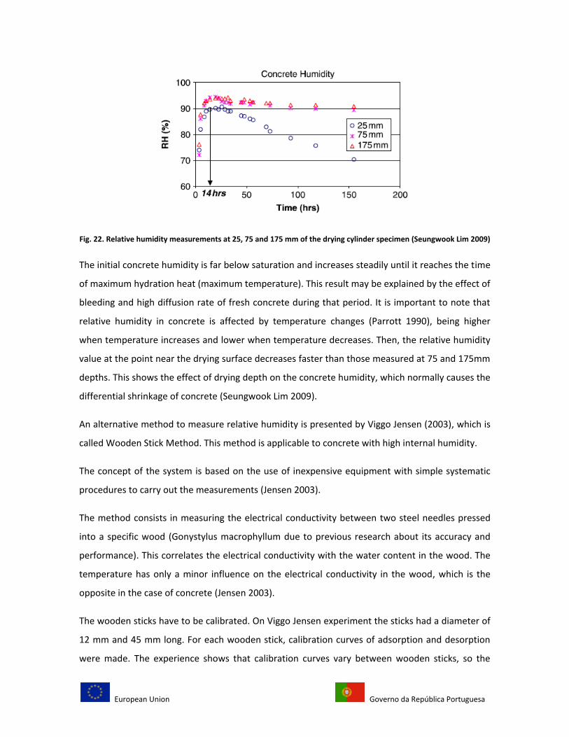
on chilled mirror technology with a ± 2% error range. The results are presented in the figure 22
(Seungwook Lim 2009).
European Union Governo da República Portuguesa
Fig. 22. Relative humidity measurements at 25, 75 and 175 mm of the drying cylinder specimen (Seungwook Lim 2009)
The initial concrete humidity is far below saturation and increases steadily until it reaches the time
of maximum hydration heat (maximum temperature). This result may be explained by the effect of
bleeding and high diffusion rate of fresh concrete during that period. It is important to note that
relative humidity in concrete is affected by temperature changes (Parrott 1990), being higher
when temperature increases and lower when temperature decreases. Then, the relative humidity
value at the point near the drying surface decreases faster than those measured at 75 and 175mm
depths. This shows the effect of drying depth on the concrete humidity, which normally causes the
differential shrinkage of concrete (Seungwook Lim 2009).
An alternative method to measure relative humidity is presented by Viggo Jensen (2003), which is
called Wooden Stick Method. This method is applicable to concrete with high internal humidity.
The concept of the system is based on the use of inexpensive equipment with simple systematic
procedures to carry out the measurements (Jensen 2003).
The method consists in measuring the electrical conductivity between two steel needles pressed
into a specific wood (Gonystylus macrophyllum due to previous research about its accuracy and
performance). This correlates the electrical conductivity with the water content in the wood. The
temperature has only a minor influence on the electrical conductivity in the wood, which is the
opposite in the case of concrete (Jensen 2003).
The wooden sticks have to be calibrated. On Viggo Jensen experiment the sticks had a diameter of
12 mm and 45 mm long. For each wooden stick, calibration curves of adsorption and desorption
were made. The experience shows that calibration curves vary between wooden sticks, so the
European Union Governo da República Portuguesa
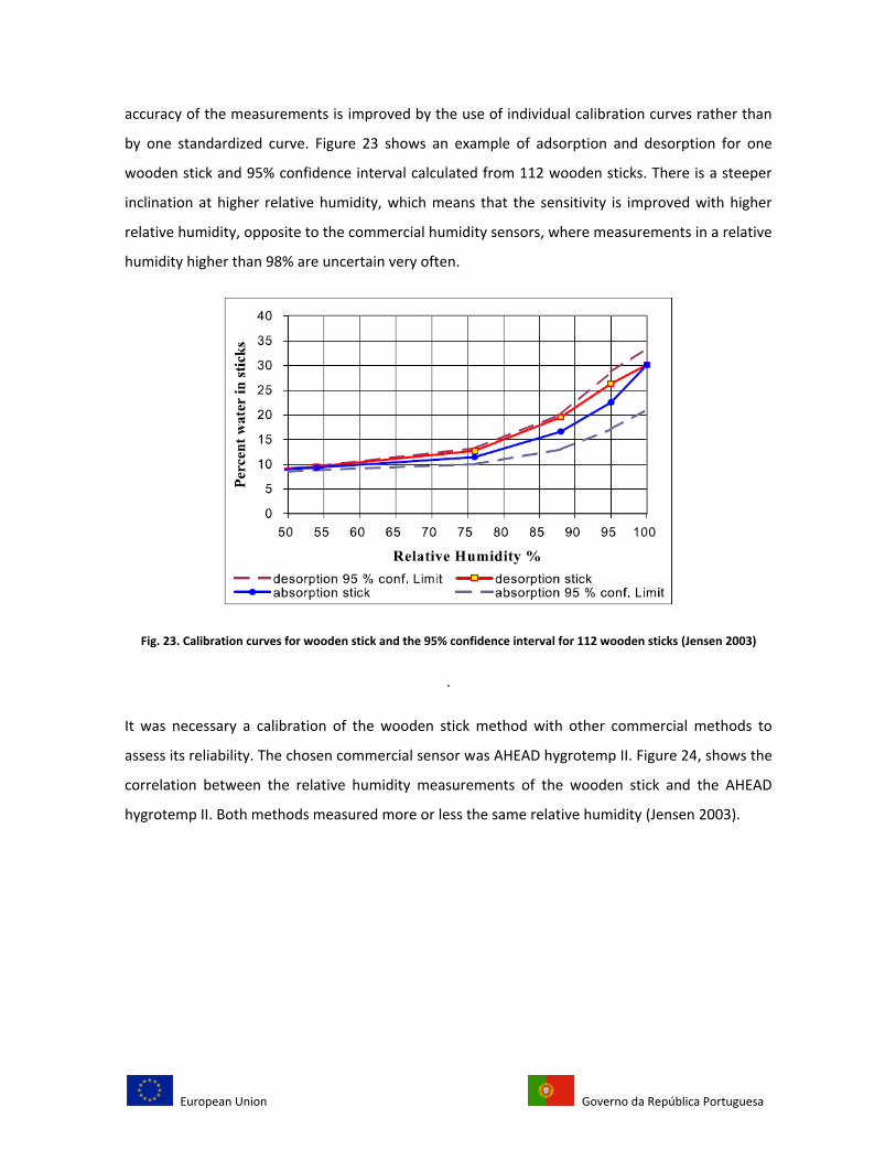
accuracy of the measurements is improved by the use of individual calibration curves rather than
by one standardized curve. Figure 23 shows an example of adsorption and desorption for one
wooden stick and 95% confidence interval calculated from 112 wooden sticks. There is a steeper
inclination at higher relative humidity, which means that the sensitivity is improved with higher
relative humidity, opposite to the commercial humidity sensors, where measurements in a relative
humidity higher than 98% are uncertain very often.
Fig. 23. Calibration curves for wooden stick and the 95% confidence interval for 112 wooden sticks (Jensen 2003)
.
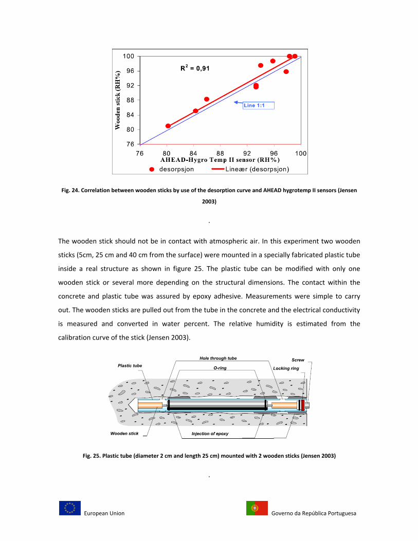
It was necessary a calibration of the wooden stick method with other commercial methods to
assess its reliability. The chosen commercial sensor was AHEAD hygrotemp II. Figure 24, shows the
correlation between the relative humidity measurements of the wooden stick and the AHEAD
hygrotemp II. Both methods measured more or less the same relative humidity (Jensen 2003).
European Union Governo da República Portuguesa
Fig. 24. Correlation between wooden sticks by use of the desorption curve and AHEAD hygrotemp II sensors (Jensen
2003)
.
The wooden stick should not be in contact with atmospheric air. In this experiment two wooden
sticks (5cm, 25 cm and 40 cm from the surface) were mounted in a specially fabricated plastic tube
inside a real structure as shown in figure 25. The plastic tube can be modified with only one
wooden stick or several more depending on the structural dimensions. The contact within the
concrete and plastic tube was assured by epoxy adhesive. Measurements were simple to carry
out. The wooden sticks are pulled out from the tube in the concrete and the electrical conductivity
is measured and converted in water percent. The relative humidity is estimated from the
calibration curve of the stick (Jensen 2003).
Fig. 25. Plastic tube (diameter 2 cm and length 25 cm) mounted with 2 wooden sticks (Jensen 2003)
.
European Union Governo da República Portuguesa
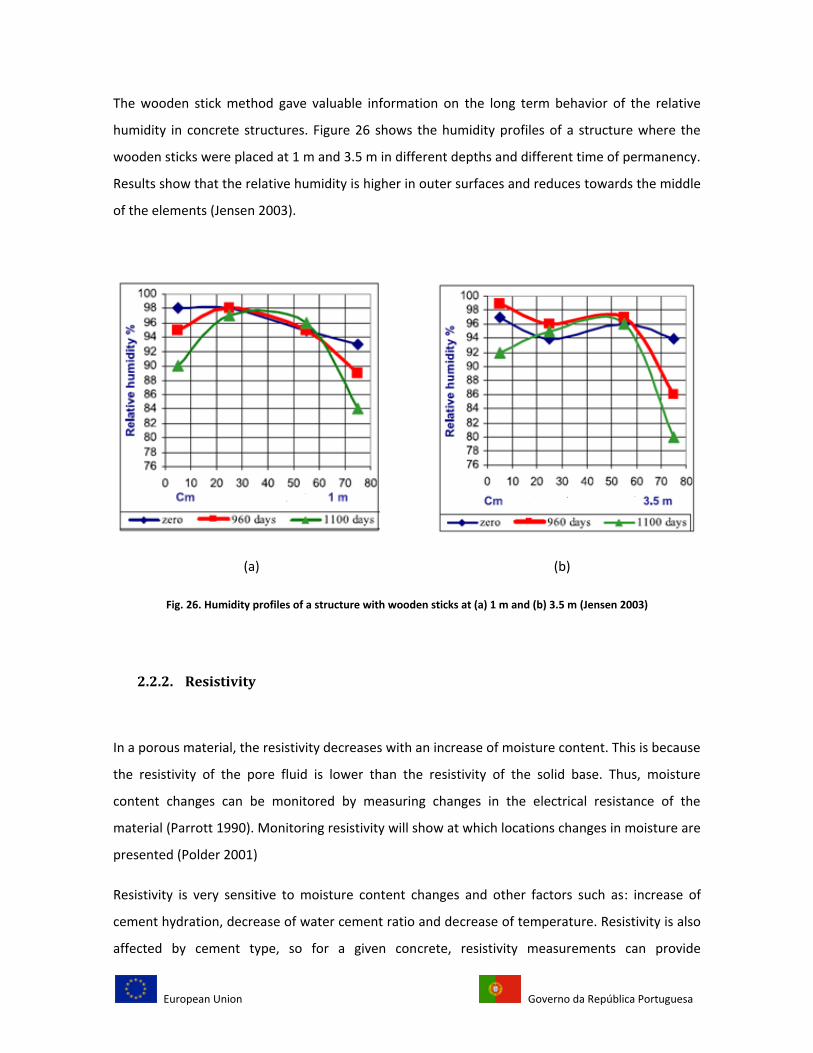
The wooden stick method gave valuable information on the long term behavior of the relative
humidity in concrete structures. Figure 26 shows the humidity profiles of a structure where the
wooden sticks were placed at 1 m and 3.5 m in different depths and different time of permanency.
Results show that the relative humidity is higher in outer surfaces and reduces towards the middle
of the elements (Jensen 2003).
(a) (b)
Fig. 26. Humidity profiles of a structure with wooden sticks at (a) 1 m and (b) 3.5 m (Jensen 2003)
2.2.2. Resistivity
In a porous material, the resistivity decreases with an increase of moisture content. This is because
the resistivity of the pore fluid is lower than the resistivity of the solid base. Thus, moisture
content changes can be monitored by measuring changes in the electrical resistance of the
material (Parrott 1990). Monitoring resistivity will show at which locations changes in moisture are
presented (Polder 2001)
Resistivity is very sensitive to moisture content changes and other factors such as: increase of
cement hydration, decrease of water cement ratio and decrease of temperature. Resistivity is also
affected by cement type, so for a given concrete, resistivity measurements can provide
European Union Governo da República Portuguesa
information about moisture gradients along time (Parrott 1990), and for a particular structure, as
more porosity the readings for resistivity will be lower because less material will interfere with the
current passing through the material (Polder 2001). As established, electrical conduction occurs
primarily due to ion transport through the pore solution in a cement based system. Therefore,
electrical conduction is dependent on both pore solution conductivity and porosity (Xiao and Li
2008).
The method requires embedding sensors or wires in concrete to measure the resistivity changes,
thus, the readings will not be reliable without careful calibration for each test. This requires at
least two electrodes. A voltage is applied between the electrodes and resulting current is
measured. The ratio of voltage to current gives a resistance (Ω). The resistivity is obtained either
from theoretical considerations or from calibration using standard concrete samples or
electrolytes of known resistivity (Polder 2001).
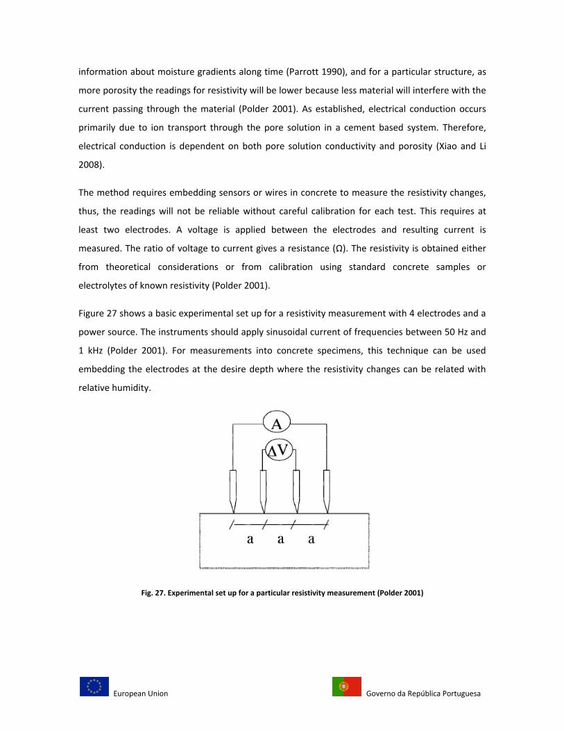
Figure 27 shows a basic experimental set up for a resistivity measurement with 4 electrodes and a
power source. The instruments should apply sinusoidal current of frequencies between 50 Hz and
1 kHz (Polder 2001). For measurements into concrete specimens, this technique can be used
embedding the electrodes at the desire depth where the resistivity changes can be related with
relative humidity.
Fig. 27. Experimental set up for a particular resistivity measurement (Polder 2001)
European Union Governo da República Portuguesa
Temperature affects the resistivity measurements. In fact, when the temperature increases the
resistivity decreases, and vice versa. This is caused by the influence of temperature on ion
mobility, ion-ion and ion-solid interactions. Based on laboratory research, the temperature effect
vary with moisture content with 3% for saturated and 5% for dry concrete for each degree Kelvin
temperature change(Polder 2001).
Electrical conduction occurs primarily due to ion transport through the pore solution in a cement
based material. The electrical conduction depends of the porosity. As the results for conventional
electrical measurement are problematic due to the problems of contact between electrodes and
fresh cement, such as electrochemical reactions and shrinkage cracks, recently, a non contact
electrical resistivity method (NC-ERM) has been developed to measure the resistivity development
within concrete mixes. The NC-ERM eliminates the contact problems between electrodes and
surrounding materials in conventional set ups for impedance measurements since there are no
electrodes in the set up (Xiao and Li 2008).
Other electrical measurement methods have been applied, but the results when conventional
electrical measurement is adopted are problematic due to deficiencies in terms of contact
between electrodes and fresh concrete, caused by electrochemical reactions (Xiao and Li 2008). As
the NC-ERM method has not been applied to measure moisture or relative humidity profiles, is
possible to relate resistivity values or impedance changes with the lost of moisture at any depth.
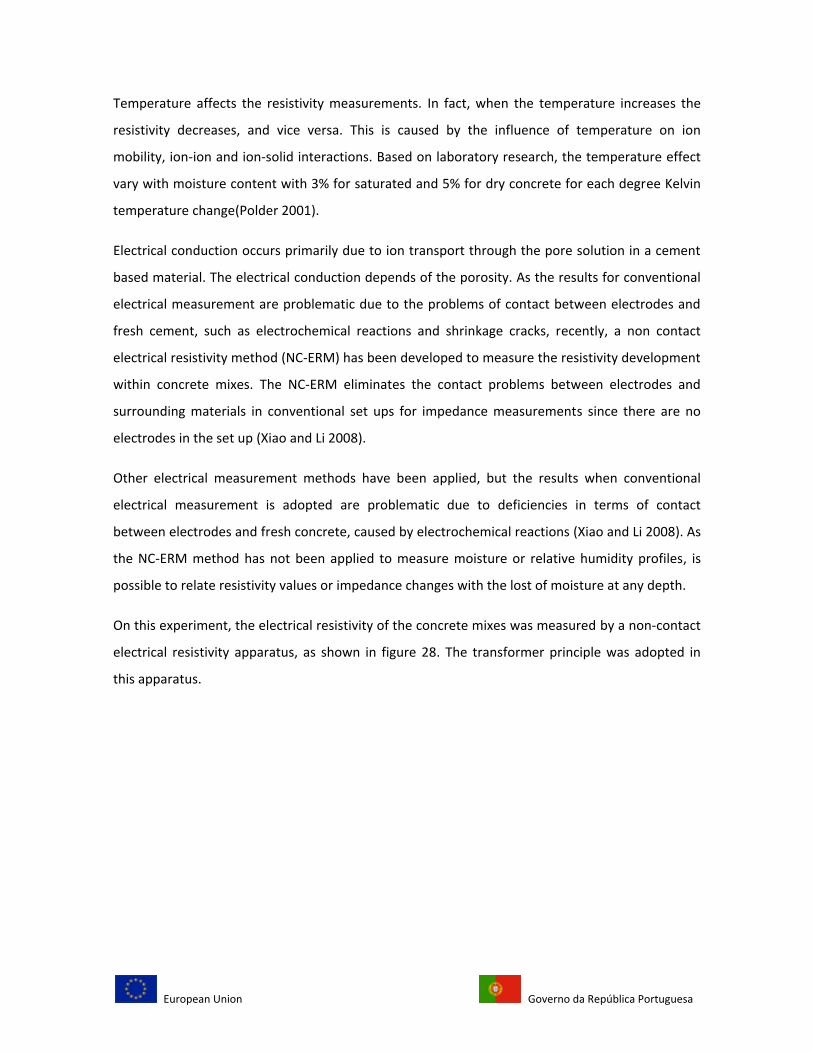
On this experiment, the electrical resistivity of the concrete mixes was measured by a non-contact
electrical resistivity apparatus, as shown in figure 28. The transformer principle was adopted in
this apparatus.
European Union Governo da República Portuguesa
(a) (b)
Fig. 28. (a) Non-contact electrical resistivity apparatus (b) mold cross section (Xiao and Li 2008)
When an AC voltage from the generator is applied to the primary coil of the transformer, a
toroidal voltage, V, is inducted in the ring sample that acts as the secondary coil of the
transformer. The toroidal current, I, can be measured by a leakage current meter and hence the
resistance of the concrete can be obtained through V and I, based on ohm´s law. For the
trapezoidal cross section specimen with radius r1, r2, r3 and r4 (r1< r2 < r3 < r4) represented in figure
28b.The resistivity ( ) can be obtained from ohm´s law:
=
where h represents the height of the specimen´s cross section.
2.2.3. Dielectric properties
A dielectric is an electrical insulator that can be polarized by an applied electric field. When a
dielectric is placed in an electric field, electric charges do not flow through the material, as in a
conductor, but only slightly shift from their average equilibrium positions causing dielectric
polarization. Due to dielectric polarization, positive charges are displaced toward the field and
negative charges shift in the opposite direction. This creates an internal electric field that partly
European Union Governo da República Portuguesa
compensates the external field inside the dielectric. If a dielectric is composed of weakly bonded
molecules, those molecules not only become polarized, but also reorient so that their symmetry
axis aligns to the field.
Although the term "insulator" implies low electrical conduction, "dielectric" is typically used to
describe materials with a high polarizability. A common example of a dielectric is the electrically
insulating material between the metallic plates of a capacitor. The polarization of the dielectric by
the applied electric field increases the capacitor's surface charge.
Development of Microwave methods for moisture measurements started around 1955 but is not
until 1980 when inexpensive , solid state devices for microwave generation and detection became
available, that the method became more popular (Parrott 1990).
In the microwave methods two components are considered, the attenuation of penetrating
microwave bean, also called imaginary component for the fact that refers to the microwave power
itself, and the phase change(or real component), which relates the microwave passing through the
beam suffering a reduction of the wavelength in each phase of the specimen. In a porous material
both the real and imaginary components of permittivity change with moisture content. It has been
found that measurements of the real and imaginary components or, more commonly, attenuation
and phase change can often be combined to obtain a measure of moisture content that is
independent of density. This avoids the need for supplementary methods of density measurement
(Parrott 1990).
Microwave attenuation measurements use a transmitter on one side of a sample and a receiver on
the opposite side. In such a case the sampled volume can be measured with reasonable certainty.
However, attenuation increases at higher frequencies and at high moisture contents in the
sample, hence, higher frequencies and high moisture contents should be avoid for measurements
using microwave attenuation.
It is possible to test with microwave attenuation methods from one side of a sample by microwave
reflection or the resonance of a microwave cavity. However, most be considered that the energy
of a penetrating microwave beam diminishes exponentially with depth. Then, the interpretation of
reflection or resonance data can be uncertain with regard to the sampled volume and moisture
gradients. (Parrott 1990).
European Union Governo da República Portuguesa
Dielectric properties have considerable potential for moisture measurement in concrete where
attenuation can be measured (Parrott 1990).
2.2.4. Thermal properties
On the same way of the capacitive methods, resistivity method or dielectric properties, the
moisture content of a porous material can be determined non-destructively from local
measurements of thermal conductivity or diffusivity if calibration data is available to relate
thermal properties with moisture content (Parrott 1990). Small temperature probes and heaters
are implanted or embedded in concrete or any porous material and the thermal response is
measured as a function of time after the heater or any thermal source is activated. The equipment
is inexpensive and is small enough to allow measurements of moisture gradients.
Variations of the thermal conductivity with moisture content from dry to saturated are
approximately linear so thermal conductivity reflects the total evaporable water and does not
distinguish absorbed and free water (Parrott 1990).
The thermal properties depend upon numerous factors such as aggregate content, aggregate type,
concrete density and air entrainment. These are disadvantages at the moment of using this
method (Parrott 1990).
2.2.5. Infrared Adsorption
Water absorbs electromagnetic radiation at specific wavelengths in the 1 to 14µm infrared portion
of the spectrum. Each absorption band is characteristic of a particular vibration mode of the water
molecule. Monitoring changes of absorption at the one or more wavelengths it is possible to
determine moisture content in porous materials. Only a thin layer of the sample is penetrated by
the infrared beam, so measurements are normally undertaken in the reflection mode rather than
the transmission mode (Parrott 1990).
European Union Governo da República Portuguesa
Cornell et al. (1972) described an infrared reflection instrument operating at wavelengths of
1.94µm and 1.80µm to obtain moisture sensitive and reference signals respectively. The
instrument contained sealed reference samples for calibration. They proposed measurements on
the flat-bottomed surfaces of holes drilled to different depths to determine moisture gradients in
a drying sample. The application of this method for moisture measurements in concrete is limited
by the low penetration depth of an infrared beam (Parrott 1990).
Infrared radiation may be detected over a relatively large area of a structure using a video camera
fitted with an infrared detector and a scanner. It is possible to obtain real-time image surface
temperature variations. Wavelength bands detected are relatively broad and are not specific to
particular vibration modes of the water molecule. However moisture conditions affect the heat
flow through the imaged surface and corresponding surface temperature variations can be
detected (Parrott 1990).
This method is more accurate to determine moisture conditions in a surface rather than to
determine moisture profiles inside concrete. The penetration depth is too small to obtain reliable
readings.
2.2.6. Neutron scattering
When fast neutrons are emitted from a radioactive source such as americium 241 they penetrate
into concrete and collide with the nuclei of atoms composing the concrete. The velocity reduction
is greatest for collisions with nuclei that have mass comparable to that of the neutron. After a
series of collisions the slow neutrons can be monitored using a detector that incorporates a slow
neutron absorber. Hydrogen in water molecules is the dominant source of light nuclei that causes
the production of slow neutrons in concrete. Thus, in the absence of organic material and other
sources of hydrogen, the slow neutron count is primarily a measure of the total water content.
The method does not distinguish chemically bound, absorbed and free water, unless using neutron
scattering equipment that is fitted with high resolution detectors. Common elements in cement
and concrete such as silicon, calcium, aluminum and oxygen cause little absorption of slow
neutrons but chlorine can reduce the slow neutron count and the indicated moisture content
(Parrott 1990).
European Union Governo da República Portuguesa
Commercial equipment often includes a source and a detector for gamma radiation, so
complementary measurements of density can be obtained as well. Then, the health concern about
the radioactive methods in the design of commercial equipment is necessary and the equipment
has to be licensed, use trained staff and proceed with extreme care. This method is not
appropriate for routine use (Parrott 1990).
Some authors examined possible materials for calibration, but samples of the test material at
known moisture contents provide the most reliable calibration data.
2.2.7. Nanotechnology/Microelectromechanical systems sensors
Current methods for temperature and internal relative humidity evaluation, which rely on
destructive testing systems are expensive and time consuming. In addition, these techniques
require intensive labor and special equipment to gain access to remote locations. Cutting edge
nanotechnology/MEMS, which have matured in recent years, represent and innovative solution to
current monitoring systems, leading to wireless, inexpensive, durable, compact, and high-density
information collection, processing and storage devices for structural health monitoring (Norris,
Saafi et al. 2008).
MEMS devices are being manufactured using the same materials and process as microelectronic
devices such as microprocessors and memory chips. These manufacturing methods permit the
devices to be small and inexpensive enough to be distributed throughout a structure in numbers
from hundreds to millions. The common manufacturing process also permits the integration of
mechanical actuators with electronics for control, processing and communication. This
combination introduces the ability to direct sense and interact with the structural environment
(Norris, Saafi et al. 2008).
There are several advantages of a MEMS-based monitoring system over other methods of
condition assessment and monitoring. MEMS devices can be embedded, bringing their readings
closer to the true in situ properties of the structure and not estimatives based on external visual
inspections or expensive non destructive tests. MEMS technology has the potential to measure the
European Union Governo da República Portuguesa
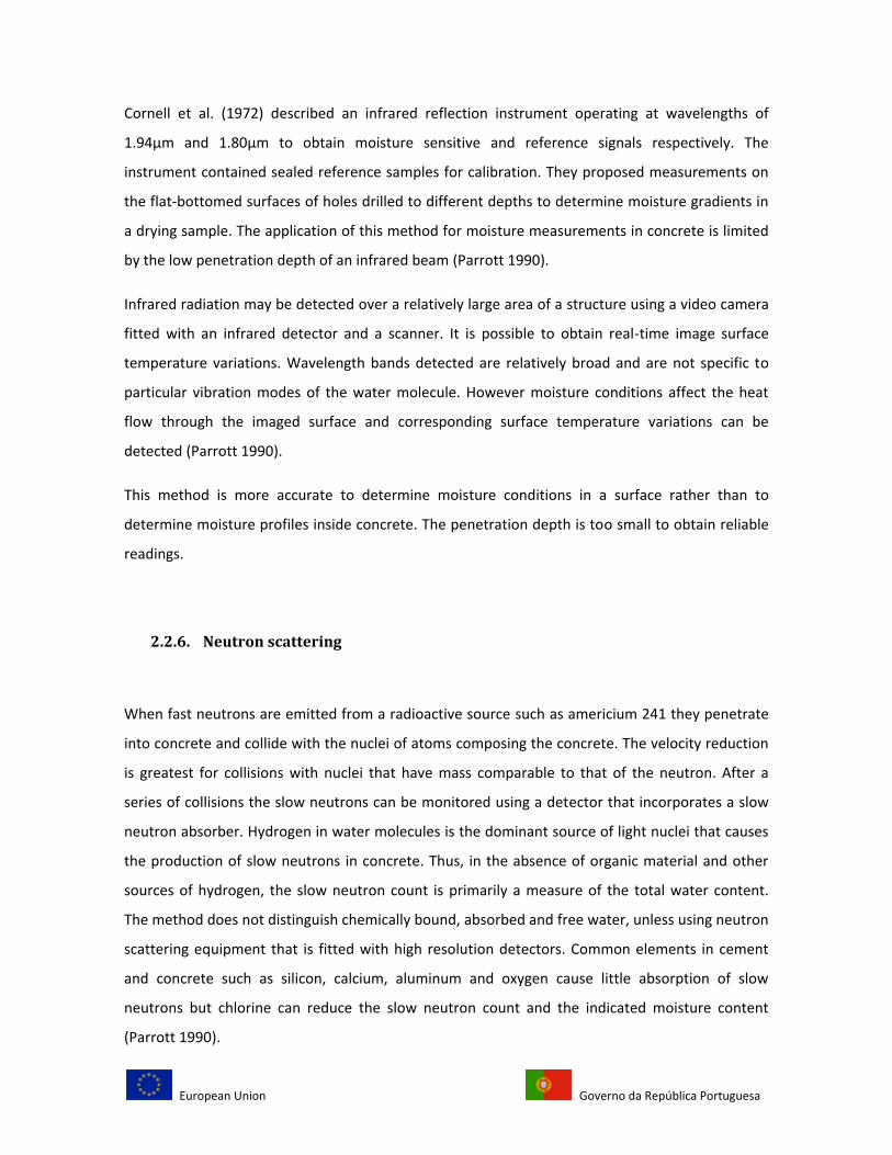
properties of interest directly. There are small and encapsulated, which make them difficult to
damage (see figure 29) while wireless technologies make them easy to embed and interrogate
(Norris, Saafi et al. 2008) .
Fig. 29. Packaged MEMS sensors (Norris, Saafi et al. 2008) (directindustry.com)
Due to batch fabrication, the current cost of the device is about $25 and this cost can decrease in
the next few years.
The numbers of devices to be embed in the concrete without affecting the mechanical and
physical properties of the hardened material will depend mainly on the size and type of the
structure and the environmental conditions. The device can also be uniformly embedded into
concrete structure to measure moisture and temperature distribution along concrete thickness
(Norris, Saafi et al. 2008).
Nonetheless, MEMS sensing technology brings three advantages to its application to civil
infrastructures: miniaturization, multiple components and microelectronics. Another advantage is
that the small size of packaged MEMS sensors allows them to be embedded into concrete
structures without compromising the geometry, weight or other inherent properties of structures
(Norris, Saafi et al. 2008).
A preliminary evaluation of embedded MEMS sensor response was made to evaluate the
feasibility of embedding this sensor to measure relative humidity and temperature in a specific
depth in a concrete specimen. Five concrete cylinders of 152 mm (diameter) x 305 mm (length)
with a water-cement ratio of 0.55 were tested. For each specimen a MEMS sensor was embedded
European Union Governo da República Portuguesa
at the middle depth of the specimens in a cured room a 22° C at 50% of relative humidity. A data
acquisition system was used to power the embedded device and monitor the moisture
temperature trough electrical cables(Norris, Saafi et al. 2008).
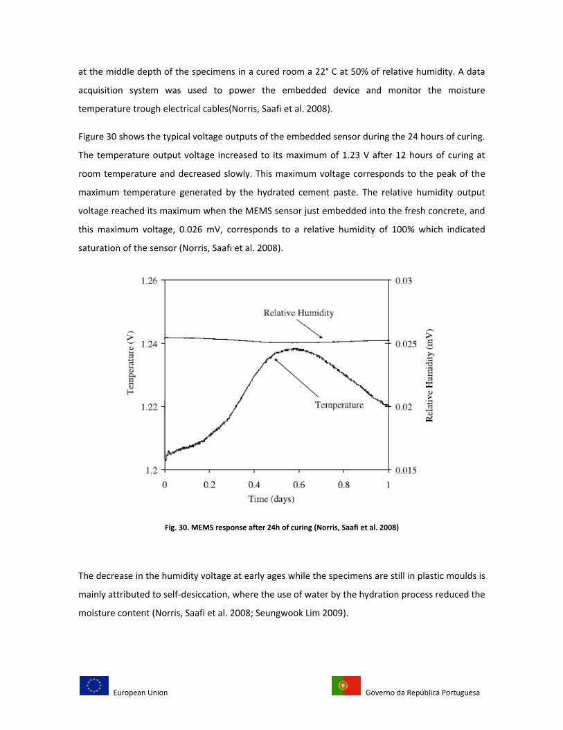
Figure 30 shows the typical voltage outputs of the embedded sensor during the 24 hours of curing.
The temperature output voltage increased to its maximum of 1.23 V after 12 hours of curing at
room temperature and decreased slowly. This maximum voltage corresponds to the peak of the
maximum temperature generated by the hydrated cement paste. The relative humidity output
voltage reached its maximum when the MEMS sensor just embedded into the fresh concrete, and
this maximum voltage, 0.026 mV, corresponds to a relative humidity of 100% which indicated
saturation of the sensor (Norris, Saafi et al. 2008).
Fig. 30. MEMS response after 24h of curing (Norris, Saafi et al. 2008)
The decrease in the humidity voltage at early ages while the specimens are still in plastic moulds is
mainly attributed to self-desiccation, where the use of water by the hydration process reduced the
moisture content (Norris, Saafi et al. 2008; Seungwook Lim 2009).
European Union Governo da República Portuguesa
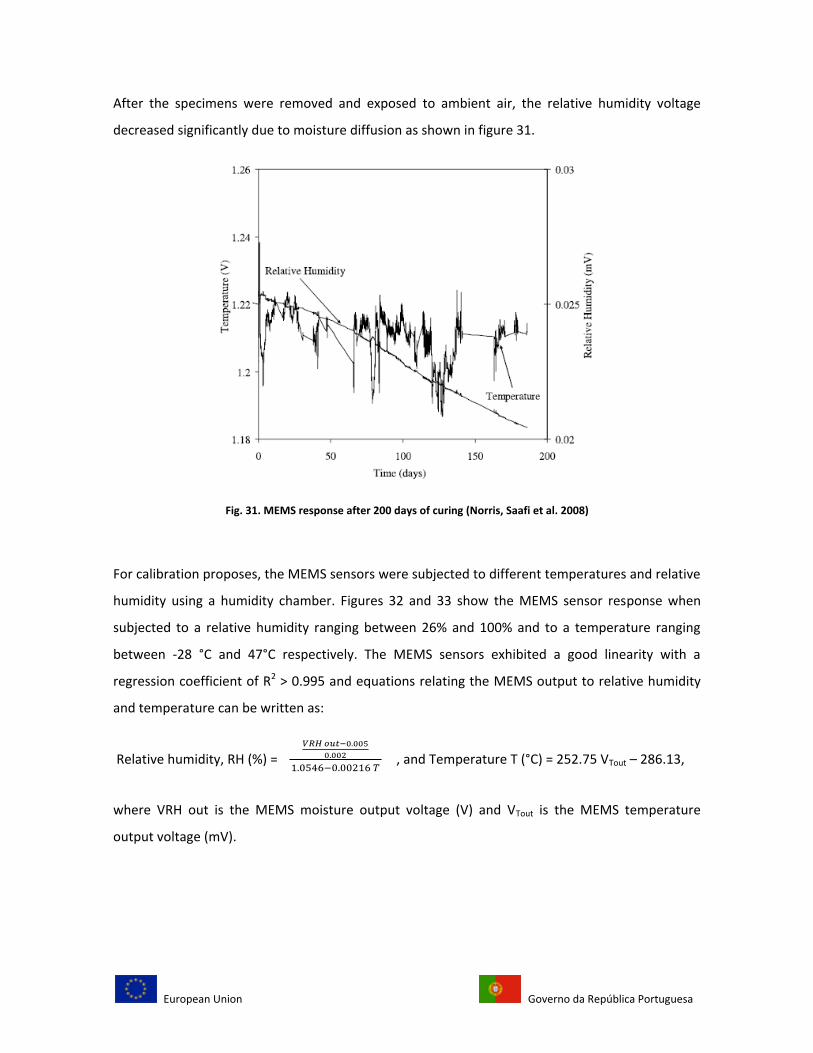
After the specimens were removed and exposed to ambient air, the relative humidity voltage
decreased significantly due to moisture diffusion as shown in figure 31.
Fig. 31. MEMS response after 200 days of curing (Norris, Saafi et al. 2008)
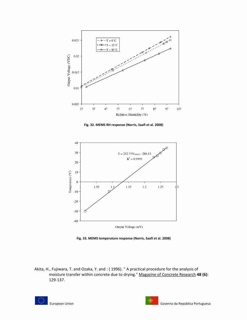
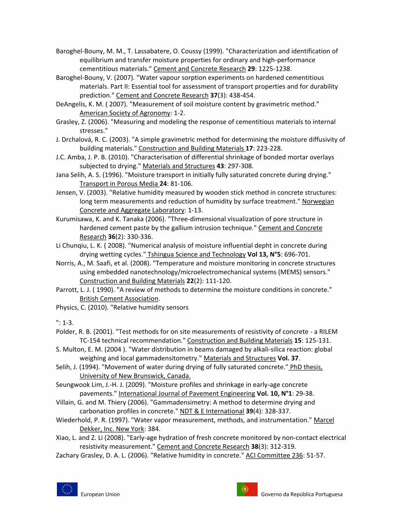
For calibration proposes, the MEMS sensors were subjected to different temperatures and relative
humidity using a humidity chamber. Figures 32 and 33 show the MEMS sensor response when
subjected to a relative humidity ranging between 26% and 100% and to a temperature ranging
between -28 °C and 47°C respectively. The MEMS sensors exhibited a good linearity with a
regression coefficient of R2 > 0.995 and equations relating the MEMS output to relative humidity
and temperature can be written as:
Relative humidity, RH (%) = , and Temperature T (°C) = 252.75 VTout – 286.13,
where VRH out is the MEMS moisture output voltage (V) and VTout is the MEMS temperature
output voltage (mV).
European Union Governo da República Portuguesa
Fig. 32. MEMS RH response (Norris, Saafi et al. 2008)
Fig. 33. MEMS temperature response (Norris, Saafi et al. 2008)
(Villain and Thiery 2006; Norris, Saafi et al. 2008; Akita and : 1996) Akita, H., Fujiwara, T. and Ozaka, Y. and : ( 1996). " A practical procedure for the analysis of
moisture transfer within concrete due to drying." Magazine of Concrete Research 48 (6): 129-137.
European Union Governo da República Portuguesa
Baroghel-Bouny, M. M., T. Lassabatere, O. Coussy (1999). "Characterization and identification of equilibrium and transfer moisture properties for ordinary and high-performance cementitious materials." Cement and Concrete Research 29: 1225-1238.
Baroghel-Bouny, V. (2007). "Water vapour sorption experiments on hardened cementitious materials. Part II: Essential tool for assessment of transport properties and for durability prediction." Cement and Concrete Research 37(3): 438-454.
DeAngelis, K. M. ( 2007). "Measurement of soil moisture content by gravimetric method." American Society of Agronomy: 1-2.
Grasley, Z. (2006). "Measuring and modeling the response of cementitious materials to internal stresses."
J. Drchalová, R. C. (2003). "A simple gravimetric method for determining the moisture diffusivity of building materials." Construction and Building Materials 17: 223-228.
J.C. Amba, J. P. B. (2010). "Characterisation of differential shrinkage of bonded mortar overlays subjected to drying." Materials and Structures 43: 297-308.
Jana Selih, A. S. (1996). "Moisture transport in initially fully saturated concrete during drying." Transport in Porous Media 24: 81-106.
Jensen, V. (2003). "Relative humidity measured by wooden stick method in concrete structures: long term measurements and reduction of humidity by surface treatment." Norwegian Concrete and Aggregate Laboratory: 1-13.
Kurumisawa, K. and K. Tanaka (2006). "Three-dimensional visualization of pore structure in hardened cement paste by the gallium intrusion technique." Cement and Concrete Research 36(2): 330-336.
Li Chunqiu, L. K. ( 2008). "Numerical analysis of moisture influential depht in concrete during drying wetting cycles." Tshingua Science and Technology Vol 13, N°5: 696-701.
Norris, A., M. Saafi, et al. (2008). "Temperature and moisture monitoring in concrete structures using embedded nanotechnology/microelectromechanical systems (MEMS) sensors." Construction and Building Materials 22(2): 111-120.
Parrott, L. J. ( 1990). "A review of methods to determine the moisture conditions in concrete." British Cement Association.
Physics, C. (2010). "Relative humidity sensors
": 1-3. Polder, R. B. (2001). "Test methods for on site measurements of resistivity of concrete - a RILEM
TC-154 technical recommendation." Construction and Building Materials 15: 125-131. S. Multon, E. M. (2004 ). "Water distribution in beams damaged by alkali-silica reaction: global
weighing and local gammadensitometry." Materials and Structures Vol. 37. Selih, J. (1994). "Movement of water during drying of fully saturated concrete." PhD thesis,
University of New Brunswick, Canada. Seungwook Lim, J.-H. J. (2009). "Moisture profiles and shrinkage in early-age concrete
pavements." International Journal of Pavement Engineering Vol. 10, N°1: 29-38. Villain, G. and M. Thiery (2006). "Gammadensimetry: A method to determine drying and
carbonation profiles in concrete." NDT & E International 39(4): 328-337. Wiederhold, P. R. (1997). "Water vapor measurement, methods, and instrumentation." Marcel
Dekker, Inc. New York: 384. Xiao, L. and Z. Li (2008). "Early-age hydration of fresh concrete monitored by non-contact electrical
resistivity measurement." Cement and Concrete Research 38(3): 312-319. Zachary Grasley, D. A. L. (2006). "Relative humidity in concrete." ACI Committee 236: 51-57.

European Union Governo da República Portuguesa