sensor de pressão de pneu
TRANSCRIPT

AN238Tire Pressure Monitoring (TPM) System
INTRODUCTIONThis document explains a typical tire pressure monitor-ing (TPM) system specifically intended for automotiveuse. It serves as a reference to design a real-worldsystem based on various Microchip products. A TPMsystem primarily monitors the internal temperature andpressure of an automobile's tire. There is a variety ofsystem approaches to follow, although this one is arather comprehensive auto-location system.
An auto-location system can dynamically detect theposition of a specific sensor, which is useful when tiresare rotated. The heart of the TPM system is theSensor/Transmitter (S/TX) device and it is based onMicrochip's rfPIC12F675.
SYSTEM COMPONENTSThe TPM system consists of the following majorcomponent.
• Sensor/Transmitter Device• RF Receiver Module • Low Frequency (LF) Commander Device
• Control Unit• Pressure Vessel (Tire)
FIGURE 1: TIRE PRESSURE MONITORING (TPM) SYSTEM
Authors: Ruan LourensMicrochip Technology Inc.
Curtis KellKell Laboratories
2004 Microchip Technology Inc. DS00238B-page 1
AN238
Sensor/Transmitter (S/TX) Device
There are typically five S/TX units per vehicle, one perwheel, and the spare tire. Each unit has a unique serialnumber enabling the system to distinguish betweeneach tire. When mounted within a vehicle tire, the S/TXperiodically measures internal tire pressure, tempera-ture and battery condition. It then sends a RF signalcomposed of the measured information to a centralreceiver. The device described in this document isbased on Microchip's rfPIC12F675 and the pressureand temperature sensing is performed by the SensonorSP-13, a sensor IC (www.sensonor.com). The unit isalso equipped with a LF receiver unit, used to commu-nicate to the S/TX device and to enable it from a Sleepstate.
RF Receiver Module
A central RF receiver module receives transmissionsfrom the individual S/TX devices. The receiver can alsobe used as a remote keyless entry receiver, saving onoverall system cost. The design of the RF receivermodule falls beyond the intent of this document. Afunctional RF receiver module is assumed.
LF Commander Device
The LF commander is designed to send specificcommands to the S/TX unit via a 125 kHz ASK modu-lated signal. The LF link communicates over a shortdistance (1 meter or less), thus making it capable ofcommunicating with the wheel in its immediate range.LF magnetic communications is well suited for sendingcommands to the S/TX devices. These commands,when received by the S/TX device, instruct it to carryout specific tasks.
Control Unit
The control unit is responsible for initiating communica-tions, interpreting received data and reporting therelevant information back to the vehicle. The unit willonly be treated from a system overview perspective.
Pressure Vessel
The pressure vessels (tires) are the measurementsubjects, with pressure and temperature valuesmeasured and reported.
TPM Sensor/Transmitter
TECHNICAL SPECIFICATIONS
• Modulation Format: ASK
• Operating Voltage: 2.5-3.6V• Low Voltage Alert Threshold: 2.5V• Quiescent Current: TBD
RF Specific:
• Transmit Frequency: 315 MHz• Transmit Interval: 60, 15 or 5 seconds (LF
selectable)• Power Output: +9 dBm into 50 Ω load
• Operating Current – Transmit: 12.5 mA at max RF power
LF Specific:
• Input Frequency: 125 kHz
• Input Sensitivity: TBD
Pressure Sensor Specific:
• Pressure Sensor Range: 50-637 kPa absolute• Temperature Sensor Range: -40–125°C
The schematic for the TPM S/TX is shown in AppendixA: “Schematics”.
THEORY OF OPERATION
The S/TX device comprises two integrated circuits:
• Microchip’s rfPIC12F675 MCU/RF transmitter IC• Sensonor SP-13 (pressure, temperature and
low-voltage sensor IC)
In addition, the S/TX also includes LF input circuitry.This circuitry allows the S/TX device to receive specialcommands via the LF link. Refer to Appendix A:“Schematics” for additional circuit detail.
rfPIC12F675 Transmitter IC
The rfPICTM, based on the PIC12F675, was chosen asthe heart of the S/TX for several reasons. First, thePIC12FXXX series of microcontrollers are widely usedfor transmitter applications and millions of PICmicro®
microcontroller devices are currently used in transmit-ter applications today. Second, this device features aninternal RC oscillator, thereby reducing the externalcomponent count which, directly reduces module costas well as circuit board size. Third, this device includesthe RF transmitter circuitry, which again reduces exter-nal component count, cost and overall size of the circuitboard. The rfPIC12F675 also has an internal compara-tor which plays an important role in decoding the infor-mation from the LF link. The internal comparator helpsreduce overall part count, thereby further reducingmodule cost and circuit board size. Lastly, therfPIC12F675 features a 10-bit Analog-to-Digitalconverter, allowing the designer to use analog outputpressure sensors.
The rfPIC performs three functions. It monitors the dataline from the SP-13 sensor IC and from the LF input,and assembles and transmits a RF message atperiodic intervals.
DS00238B-page 2 2004 Microchip Technology Inc.
AN238
After application of power, the rfPIC executes an initial-ization procedure and goes into a Sleep mode until astate change is detected on either the SP-13 data lineor the LF input. Either of these inputs generates awake-up, causing the rfPIC to transition into the Runmode. If the wake-up was generated by the SP-13, therfPIC reads the incoming data, assembles the data intoan appropriate message, and transmits the messagevia the RF transmitter. Once the RF message is sent,the rfPIC reenters the Sleep mode. If the wake-up wasgenerated by the LF input, the rfPIC interprets the LFmessage, executes the command and then reentersthe Sleep mode.
RF Circuitry
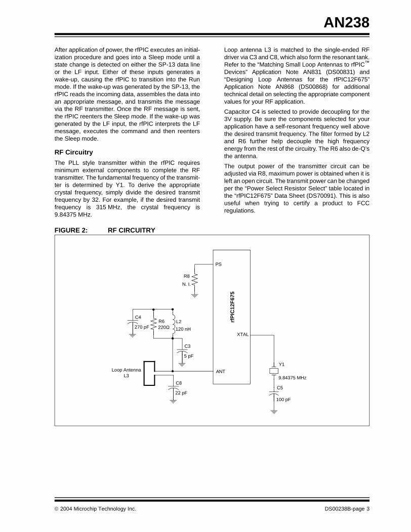
The PLL style transmitter within the rfPIC requiresminimum external components to complete the RFtransmitter. The fundamental frequency of the transmit-ter is determined by Y1. To derive the appropriatecrystal frequency, simply divide the desired transmitfrequency by 32. For example, if the desired transmitfrequency is 315 MHz, the crystal frequency is9.84375 MHz.
Loop antenna L3 is matched to the single-ended RFdriver via C3 and C8, which also form the resonant tank.Refer to the “Matching Small Loop Antennas to rfPIC™
Devices” Application Note AN831 (DS00831) and“Designing Loop Antennas for the rfPIC12F675”Application Note AN868 (DS00868) for additionaltechnical detail on selecting the appropriate componentvalues for your RF application.
Capacitor C4 is selected to provide decoupling for the3V supply. Be sure the components selected for yourapplication have a self-resonant frequency well abovethe desired transmit frequency. The filter formed by L2and R6 further help decouple the high frequencyenergy from the rest of the circuitry. The R6 also de-Q’sthe antenna.
The output power of the transmitter circuit can beadjusted via R8, maximum power is obtained when it isleft an open circuit. The transmit power can be changedper the “Power Select Resistor Select” table located inthe “rfPIC12F675” Data Sheet (DS70091). This is alsouseful when trying to certify a product to FCCregulations.
FIGURE 2: RF CIRCUITRY
ANT
PS
rfP
IC12
F67
5
Y1
9.84375 MHZ
C5
100 pF
R6220Ω
Loop Antenna
L2
120 nH
C4
270 pF
C8
22 pF
C3
5 pF
R8
N. I.
XTAL
L3
2004 Microchip Technology Inc. DS00238B-page 3

AN238
Sensonor SP-13 Sensor IC
The SP-13 sensor IC performs several functions. Itmeasures pressure, temperature, and generates a flagwhen the battery voltage drops below a predeterminedthreshold. The SP-13 has five unique modes:
1. Storage mode: If the pressure is below 1.5 bar,pressure is measured every 60 seconds but nodata is sent. If the pressure increases above1.5 bars, the component shifts into the Initialmode.
2. Initial mode: This mode occurs at power on orif the pressure increases above 1.5 bar fromStorage mode. In this mode, pressure ismeasured every 0.85 seconds and data is sentevery 0.85 seconds. This sequence is repeated256 times. After the sequence is repeated 256times, the device shifts into the Normal modeonly if pressure is above 1.5 bar. If the pressureis below 1.5 bar, the device will shift into theStorage mode.
3. Normal mode: Pressure is measured every3.4 seconds and data is transmitted every60 seconds. If the measured pressure differs bymore than 200 mbar from the reference takenevery 60 seconds, the device enters a PressureAlert mode.
4. Pressure Alert mode: It is the same measure-ment and transmitting pattern as the Initialmode.
5. High Temp Alert mode: If the temperatureexceeds 120°C, the SP-13 device enters intothe same measurement and transmitting patternas the Initial mode.
The SP-13 also includes a 32-bit identification numberthat is programmed into the device at the time ofmanufacture. This unique ID, when used by the centralreceiver, allows differentiation between S/TXs.
Sensonor, as well as several other manufacturers,continue to offer enhanced pressure sensing devices ofvarying functionality. Therefore, it is recommended thata TPM developer thoroughly research the market priorto making a final pressure sensor selection.
FIGURE 3: SENSONOR SP-13 SENSOR IC
LF Input Circuitry
The LF input is designed to receive and demodulate a125 kHz signal and transform the received data into aspecific command. The LF input circuit makes use ofthe internal comparator of the rfPIC, thereby reducingcost, module size and quiescent current. The LF inputcircuitry features a LC tank circuit that is tuned to125 kHz. The LF sensing input comprises L1 and C11.L1 is specially designed by Coilcraft for this type ofapplication. It provides good sensitivity in a compactpackage. A conventional coil could be used in its place,but overall circuit sensitivity or range would be reduced.Schottky diode D3 is used to clamp the voltage devel-oped across the LC tank to safe levels. The output ofthe LC tank circuit, after passing through current limit-ing resistor R5, is fed into the rfPIC comparator's neg-ative input. The comparator's positive input isconfigured as VREF through the rfPIC12F675’s VREF
module. The output of the comparator is then fed intoan envelope detector consisting of Schottky diode D2,capacitor C9 and resistor R3. C9 and R3 are selectedto provide adequate filtering of the LF frequency with-out rounding the edges of the desired data signal. Theoutput of the envelope detector is then fed directly intoa port pin on the rfPIC and used to process the LF data.
Without a limiting diode, the LF input circuit may beprone to being overdriven when strong LF fields arepresent. This can be seen when the LF commanderdevice is in close proximity to the S/TX device. Theenvelope detection circuit can be abandoned to reducecost, but doing so would require additional dataextraction software.
1 2 3 4 5 6 7 8
91011121314
VSSAVDD
VDDTXBC
TXDTXONGND5GND1
GND2GND3VSSREXTGND4VSS
U4
Pressure/Temperature Sensor IC
x
x
+3V
C10
0.01 µF
R45.6 MΩ SP-13_SO
rfP
IC12
F67
5
GP0
DS00238B-page 4 2004 Microchip Technology Inc.

AN238
FIGURE 4: LF CIRCUITRY
Details of the LF transmission format and the specificcommands can be found in the Section, "LF Com-mander".
RF Transmission Format
The encoding method used for this demonstrationsystem is the 1/3-2/3 PWM format with TE (basic pulseelement) time of 400 µs and a bit period of 3xTE or1.2 ms.
FIGURE 5: RF TRANSMISSION ENCODING METHOD
Preamble: The preamble is a series of 31 logic ‘1’ bitsfollowed by a single logic ‘0’ bit. The preamble allowsthe receiver to recognize the RF transmission as a validS/TX message. The preamble also allows the receiverto synchronize to the RF message, thereby compen-sating for any oscillator inaccuracies within thetransmitter. The system designer may vary the numberof preamble bits based on system requirements.Longer preamble bit lengths may be appropriate wherereceiver quiescent current is an issue. Shorterpreamble bit lengths may be appropriate where S/TXbattery usage is a concern. In either case, it is purely atrade-off between receiver quiescent current andbattery power consumed by the S/TX device.
Transmitter ID: The 32 transmitter ID bits are used touniquely identify each S/TX. A frame of 32 bits insuresthat there is a very low probability that any two S/TXswill have the same ID.
Pressure: The pressure in kPa is obtained by multiply-ing the unsigned binary value of this byte by 2.5.
Temperature: The temperature in degrees C isobtained by subtracting 40 from the unsigned value ofbyte 8.
Battery: Bit 7 of this byte indicates the batterycondition. A logic ‘1’ is considered normal while a logic‘0’ indicates a low battery voltage.
Status: This status byte contains the following informa-tion:
Bits 0 and 1: Indicate operating state of sensor IC
00 = Initial or Storage mode
01 = Normal mode
10 = Pressure Alert mode
11 = Temperature Alert mode
CRC (2 bytes): Implement according to CCITTstandards.
L1D3C11
Schottky
R5
10 kΩ
rfPIC12F675_SSOP
R351 kΩ
C9
1000 pF
LF OutLF In
COUT
GP3
CIN- D2
Schottky
220 pFInductor
Bits
Preamble 32
Transmitter ID 32
Pressure 8
Temperature 8
Battery 8
Status 8
CRC 16
TE TE TE
Logic ‘1’
TE TE TE
Logic ‘0’
2004 Microchip Technology Inc. DS00238B-page 5

AN238
LF Commander
THEORY OF OPERATION
The system proposed in this document is based on anauto-location system, enabling it to detect the positionof a specific S/TX device. This requires a LFcommander device at each wheel arc and possibly atthe spare tire mounting position.
Having a handheld LF commander unit can enable alower cost system. Although, this would require that thesystem be manually relearned after a tire rotation, theS/TX device is able to detect tire rotation or some othersystem to engage data transmission. The LFcommander device is capable of sending commands tothe S/TX device via a LF transmission such as:
• Enable RF transmissions
• Disable RF transmissions• Transmit an immediate message• Transmit at 60-second intervals
• Transmit at 15-second intervals• Transmit at 5-second intervals
The LF commander unit is based on the PIC16F628MCU device. Communication between the LFcommander and the S/TX is accomplished viamagnetic field. When the LF commander is transmittinga message, it is essentially creating a magnetic field byexciting a series LC circuit. The LC circuit is excited bythe PICmicro's PWM port. This port is set up to gener-ate a 50% duty cycle at 125 kHz. The command data isthen modulated on this 125 kHz signal in the form ofASK modulation. Functionally, this is accomplished byinstructing the PICmicro to toggle the PWM portbetween 0% and 50% duty cycle at the rate of the data.
LF TRANSMISSION FORMAT
The encoding format used in the LF link is a1/3 - 2/3 PWM format with 400 µs TE (basic pulseelement). Selecting 400 µs TE or greater insures themagnetic field generated by the series LC circuit hasadequate time to rise and decay, without requiring toomuch wave shaping of the recovered square wave inthe S/TX circuitry.
The transmission data format for the LF link is shown inFigure 6.
FIGURE 6: LF TRANSMISSION ENCODING METHOD
Preamble: The preamble is a series of 15 logic ‘1’ bitsand 1 logic ‘0’ bit. This reduces the chance of the S/TXreceiving erroneous data from electronic devices thatgenerate strong 125 kHz fields. Computer CRT's andswitching power supplies are examples of suchdevices.
Command: These 8 bits of data contains the specificcommand that the S/TX is being asked to perform.Table 1 illustrates the various commands (MSB is leftmost column).
TABLE 1: BIT FUNCTIONS
Sum Check: Calculated by adding contents of thecommand byte with ‘10101010’.
SUMMARY
TPM use in the automotive industry is growing, drivenby customer demand, improved safety, and possiblecompulsory-usage legislation. Microchip’s low-costrfPIC devices are well suited for the application andhelp reduce the overall TPM system cost.
The use of rfPIC based S/TX makes for a flexiblesolution that allows for the merging with existingsystems such as security, PKE, RKE and more.
Bits Function
01101101 Enable RF transmissions
10010010 Disable RF transmissions
10101010 Transmit an immediate RF message
10110110 Transmit at 60-second interval
11001100 Transmit at 15-second interval
11010011 Transmit at 5-second interval
Bits
Preamble 16
Command 8
Sum Check 8
TE TE TE
Logic ‘1’
TE TE TE
Logic ‘0’
DS00238B-page 6 2004 Microchip Technology Inc.

AN238
FIGURE 7: PHOTOGRAPH OF SENSOR/TRANSMITTER DEVICE
2004 Microchip Technology Inc. DS00238B-page 7

AN238
REFERENCE DOCUMENTS
The following reference documents are available fromMicrochip's web site at www.microchip.com.
1. “Low Frequency Magnetic Transmitter Design”Application Note (AN232), DS00232; MicrochipTechnology Inc.
2. “Designing Loop Antennas for the rfPIC12F675”Application Note (AN868), DS00868; MicrochipTechnology Inc.
3. “Matching Small Loop Antennas to rfPICDevices” Application Note (AN831), DS00831;Microchip Technology Inc.
4. “Magnetic Tuning of Resonant Resistors andMethods for Increasing Sensitivity” ApplicationNote (AN832), DS00832; Microchip TechnologyInc.
5. “Optimizing PLL Filters for the rfPIC12C509Aand rfHCS362” Application Note (AN846),DS00846; Microchip Technology Inc.
6. “rfPIC12F675” Data Sheet, DS70091; MicrochipTechnology Inc.
.
Note: Microchip has a confidential ApplicationNote on Magnetic Sensors, “MagneticTuning of Resonant Resistors and Meth-ods for Increasing Sensitivity” ApplicationNote, DS00832. Contact Microchip for aNon-Disclosure Agreement in order toobtain this application note.
DS00238B-page 8 2004 Microchip Technology Inc.

AN238
APPENDIX A: SCHEMATICS
FIGURE A-1: TPM SENSOR/TRANSMITTER SCHEMATIC
R1
150Ω
1 2 3 4 5 6 7 8 9 10
11121314151617181920
AN
TV
SSR
FN
CD
AT
A_A
SK
DA
TA
_FS
KF
SK
OU
TG
P2/
AN
2/T
0CK
I/IN
T/C
OU
TG
P1/
AN
1/C
IN-/
ICS
PC
LKG
P0/
AN
0/C
IN+
/ICS
PD
AT
VS
SV
DD
GP
5/T
1CK
I/OS
C1/
CLK
ING
P4/
AN
3/T
1G/O
SC
2/C
LKO
UT
GP
3/M
CLR
/VP
PR
FX
TA
LR
FE
NIN
NC
PS
VD
DR
FV
DD
RF
U1
rfP
IC12
F67
5_S
SO
P
LF_F
ILT
ER
_DA
TA
AS
K_D
AT
ALF
_IN
SE
NS
OR
_DA
TA
LF_R
AW
_DA
TA
x xx
BT
1
+3V
Y1
9.84
375
MH
Z
C1
0.01
µF
C2
270
pF
C5
100
pFD
1LE
D
R3
51kΩ
C9
1000
pF
R5
10kΩ
LF In
put C
ircui
try
LF O
ut
1 2 3 4 5 6 7891011121314
VS
SA
VD
DV
DD
TX
BC
TX
DT
XO
NG
ND
5G
ND
1G
ND
2G
ND
3V
SS
RE
XT
GN
D4
VS
S
U4
Pre
ssur
e/T
empe
ratu
re S
enso
r IC x x
+3V
C10
0.01
µF
R4
5.6
MΩ
SP
-13_
SO
R6
220Ω
R8
N. I
.
Loop
Ant
enna
D2
Sch
ottk
y
+3V
xA
SK
_DA
TA
L2 120
nH
C4
270
pF
C8
22pF
C3
5pF
L1D
3C
11S
chot
tky
220
pFIn
duct
or
L3
2004 Microchip Technology Inc. DS00238B-page 9

AN238
NOTES:
DS00238B-page 10 2004 Microchip Technology Inc.

Note the following details of the code protection feature on Microchip devices:
• Microchip products meet the specification contained in their particular Microchip Data Sheet.
• Microchip believes that its family of products is one of the most secure families of its kind on the market today, when used in the intended manner and under normal conditions.
• There are dishonest and possibly illegal methods used to breach the code protection feature. All of these methods, to our knowledge, require using the Microchip products in a manner outside the operating specifications contained in Microchip's Data Sheets. Most likely, the person doing so is engaged in theft of intellectual property.
• Microchip is willing to work with the customer who is concerned about the integrity of their code.
• Neither Microchip nor any other semiconductor manufacturer can guarantee the security of their code. Code protection does not mean that we are guaranteeing the product as “unbreakable.”
Code protection is constantly evolving. We at Microchip are committed to continuously improving the code protection features of ourproducts. Attempts to break Microchip’s code protection feature may be a violation of the Digital Millennium Copyright Act. If such actsallow unauthorized access to your software or other copyrighted work, you may have a right to sue for relief under that Act.
Information contained in this publication regarding deviceapplications and the like is intended through suggestion onlyand may be superseded by updates. It is your responsibility toensure that your application meets with your specifications.No representation or warranty is given and no liability isassumed by Microchip Technology Incorporated with respectto the accuracy or use of such information, or infringement ofpatents or other intellectual property rights arising from suchuse or otherwise. Use of Microchip’s products as criticalcomponents in life support systems is not authorized exceptwith express written approval by Microchip. No licenses areconveyed, implicitly or otherwise, under any intellectualproperty rights.
2004 Microchip Technology Inc.
Trademarks
The Microchip name and logo, the Microchip logo, Accuron, dsPIC, KEELOQ, MPLAB, PIC, PICmicro, PICSTART, PRO MATE and PowerSmart are registered trademarks of Microchip Technology Incorporated in the U.S.A. and other countries.
AmpLab, FilterLab, microID, MXDEV, MXLAB, PICMASTER, SEEVAL, SmartShunt and The Embedded Control Solutions Company are registered trademarks of Microchip Technology Incorporated in the U.S.A.
Application Maestro, dsPICDEM, dsPICDEM.net, dsPICworks, ECAN, ECONOMONITOR, FanSense, FlexROM, fuzzyLAB, In-Circuit Serial Programming, ICSP, ICEPIC, Migratable Memory, MPASM, MPLIB, MPLINK, MPSIM, PICkit, PICDEM, PICDEM.net, PICtail, PowerCal, PowerInfo, PowerMate, PowerTool, rfLAB, rfPIC, Select Mode, SmartSensor, SmartTel and Total Endurance are trademarks of Microchip Technology Incorporated in the U.S.A. and other countries.
Serialized Quick Turn Programming (SQTP) is a service mark of Microchip Technology Incorporated in the U.S.A.
All other trademarks mentioned herein are property of their respective companies.
© 2004, Microchip Technology Incorporated, Printed in the U.S.A., All Rights Reserved.
Printed on recycled paper.
DS00238B-page 11
Microchip received ISO/TS-16949:2002 quality system certification for its worldwide headquarters, design and wafer fabrication facilities in Chandler and Tempe, Arizona and Mountain View, California in October 2003. The Company’s quality system processes and procedures are for its PICmicro® 8-bit MCUs, KEELOQ® code hopping devices, Serial EEPROMs, microperipherals, nonvolatile memory and analog products. In addition, Microchip’s quality system for the design and manufacture of development systems is ISO 9001:2000 certified.

DS00238B-page 12 2004 Microchip Technology Inc.
AMERICASCorporate Office2355 West Chandler Blvd.Chandler, AZ 85224-6199Tel: 480-792-7200 Fax: 480-792-7277Technical Support: 480-792-7627Web Address: http://www.microchip.com
Atlanta3780 Mansell Road, Suite 130Alpharetta, GA 30022Tel: 770-640-0034 Fax: 770-640-0307
Boston2 Lan Drive, Suite 120Westford, MA 01886Tel: 978-692-3848 Fax: 978-692-3821
Chicago333 Pierce Road, Suite 180Itasca, IL 60143Tel: 630-285-0071 Fax: 630-285-0075
Dallas4570 Westgrove Drive, Suite 160Addison, TX 75001Tel: 972-818-7423 Fax: 972-818-2924
DetroitTri-Atria Office Building 32255 Northwestern Highway, Suite 190Farmington Hills, MI 48334Tel: 248-538-2250Fax: 248-538-2260
Kokomo2767 S. Albright Road Kokomo, IN 46902Tel: 765-864-8360Fax: 765-864-8387
Los Angeles18201 Von Karman, Suite 1090Irvine, CA 92612Tel: 949-263-1888 Fax: 949-263-1338
San Jose1300 Terra Bella AvenueMountain View, CA 94043Tel: 650-215-1444Fax: 650-961-0286
Toronto6285 Northam Drive, Suite 108Mississauga, Ontario L4V 1X5, CanadaTel: 905-673-0699 Fax: 905-673-6509
ASIA/PACIFICAustraliaSuite 22, 41 Rawson StreetEpping 2121, NSWAustraliaTel: 61-2-9868-6733 Fax: 61-2-9868-6755
China - BeijingUnit 706BWan Tai Bei Hai Bldg.No. 6 Chaoyangmen Bei Str. Beijing, 100027, ChinaTel: 86-10-85282100 Fax: 86-10-85282104China - ChengduRm. 2401-2402, 24th Floor, Ming Xing Financial TowerNo. 88 TIDU StreetChengdu 610016, ChinaTel: 86-28-86766200 Fax: 86-28-86766599China - FuzhouUnit 28F, World Trade PlazaNo. 71 Wusi RoadFuzhou 350001, ChinaTel: 86-591-7503506 Fax: 86-591-7503521China - Hong Kong SARUnit 901-6, Tower 2, Metroplaza223 Hing Fong RoadKwai Fong, N.T., Hong KongTel: 852-2401-1200 Fax: 852-2401-3431China - ShanghaiRoom 701, Bldg. BFar East International PlazaNo. 317 Xian Xia RoadShanghai, 200051Tel: 86-21-6275-5700 Fax: 86-21-6275-5060China - ShenzhenRm. 1812, 18/F, Building A, United PlazaNo. 5022 Binhe Road, Futian DistrictShenzhen 518033, ChinaTel: 86-755-82901380 Fax: 86-755-8295-1393China - ShundeRoom 401, Hongjian Building, No. 2 Fengxiangnan Road, Ronggui Town, ShundeDistrict, Foshan City, Guangdong 528303, ChinaTel: 86-757-28395507 Fax: 86-757-28395571China - QingdaoRm. B505A, Fullhope Plaza,No. 12 Hong Kong Central Rd.Qingdao 266071, ChinaTel: 86-532-5027355 Fax: 86-532-5027205IndiaDivyasree Chambers1 Floor, Wing A (A3/A4)No. 11, O’Shaugnessey RoadBangalore, 560 025, IndiaTel: 91-80-2290061 Fax: 91-80-2290062JapanBenex S-1 6F3-18-20, ShinyokohamaKohoku-Ku, Yokohama-shiKanagawa, 222-0033, JapanTel: 81-45-471- 6166 Fax: 81-45-471-6122
Korea168-1, Youngbo Bldg. 3 FloorSamsung-Dong, Kangnam-KuSeoul, Korea 135-882Tel: 82-2-554-7200 Fax: 82-2-558-5932 or 82-2-558-5934Singapore200 Middle Road#07-02 Prime CentreSingapore, 188980Tel: 65-6334-8870 Fax: 65-6334-8850TaiwanKaohsiung Branch30F - 1 No. 8Min Chuan 2nd RoadKaohsiung 806, TaiwanTel: 886-7-536-4818Fax: 886-7-536-4803TaiwanTaiwan Branch11F-3, No. 207Tung Hua North RoadTaipei, 105, TaiwanTel: 886-2-2717-7175 Fax: 886-2-2545-0139
EUROPEAustriaDurisolstrasse 2A-4600 WelsAustriaTel: 43-7242-2244-399Fax: 43-7242-2244-393DenmarkRegus Business CentreLautrup hoj 1-3Ballerup DK-2750 DenmarkTel: 45-4420-9895 Fax: 45-4420-9910FranceParc d’Activite du Moulin de Massy43 Rue du Saule TrapuBatiment A - ler Etage91300 Massy, FranceTel: 33-1-69-53-63-20 Fax: 33-1-69-30-90-79GermanySteinheilstrasse 10D-85737 Ismaning, GermanyTel: 49-89-627-144-0 Fax: 49-89-627-144-44ItalyVia Quasimodo, 1220025 Legnano (MI)Milan, Italy Tel: 39-0331-742611 Fax: 39-0331-466781NetherlandsP. A. De Biesbosch 14NL-5152 SC Drunen, NetherlandsTel: 31-416-690399 Fax: 31-416-690340United Kingdom505 Eskdale RoadWinnersh TriangleWokingham Berkshire, England RG41 5TUTel: 44-118-921-5869Fax: 44-118-921-5820
01/26/04
WORLDWIDE SALES AND SERVICE