pw technology in energy recovery bpsl cdq project
TRANSCRIPT
* Technical contribution to the 45º Seminário de Redução de Minério de Ferro e Matérias-primas, to 16º Simpósio Brasileiro de Minério de Ferro and to 3º Simpósio Brasileiro de Aglomeração de Minério de Ferro, part of the ABM Week, August 17th-21st, 2015, Rio de Janeiro, RJ, Brazil.
PW TECHNOLOGY IN ENERGY RECOVERY: BPSL CDQ PROJECT*
Antonio Esposito1
Helênio Resende Silva Junior2 Fabrizio Strobino3
Riccardo Calcagno4
Andrea Fabbri5
Francesco Lambardi6 Abstract Saving energy and reducing resource’s consumption by minimizing emissions are today great challenges in the coking industry worldwide. In order to achieve satisfying results, equipment as well as technology should be continuously improved and designed to minimize the energy requirements and to maximize the recovery of materials and energy. The sensible heat in coke pushed out of oven chamber takes up 35 ÷ 40 % of energy consumption of coke oven. Usually the coke thermal energy is lost during traditional coke wet quenching, necessary to reduce the coke temperature for the storage and the following use in steelmaking processes. BPSL CDQ project is a sample how Paul Wurth’s technology allows to reach the energy saving goal and offers an alternative to traditional quenching. With the adoption of Coke Dry Quenching process, a considerable amount of this sensible heat in the coke can be recovered by producing steam; its production depends on various parameters, some of them battery related (Volatile Matters in red hot coke) and others CDQ system related (coke burning losses, superheated steam characteristics (i.e. P,T)), greatly depending also on boiler efficiency (heat exchange efficiency, insulation of the boiler itself, air leakage, etc.). The adoption of CDQ process reduces also the water consumptions in comparison with traditional quenching Keywords: Energy recovery, Coke quenching; Water saving. 1 Dott. Ing., Head of Coke oven plant department, Paul Wurth Italia S.p.a., Genoa, Italy. 2 Ing. MBA Marketing Sales Senior Coke Coordin., Paul Wurth Brazil, Belo Horizonte, MG, Brazil. 3 Dr. Ing., Technical Manager, Engineering Dept. - Paul Wurth IHI Co., Ltd. – Japan. 4 Ing. Senior Project Engineer CDQ, Coke oven plant department Paul Wurth Italia S.p.a., Genoa,
Italy. 5 Ing. Project Engineer CDQ, Coke oven plant department Paul Wurth Italia S.p.a., Genoa, Italy. 6 Ing. Sales Manager Coal Coking & Innovative Technologies Sales Paul Wurth Italia S.p.a., Genoa,
Italy.
555
ISSN 2176-3135
* Technical contribution to the 45º Seminário de Redução de Minério de Ferro e Matérias-primas, to 16º Simpósio Brasileiro de Minério de Ferro and to 3º Simpósio Brasileiro de Aglomeração de Minério de Ferro, part of the ABM Week, August 17th-21st, 2015, Rio de Janeiro, RJ, Brazil.
1 INTRODUCTION At the end of 2011 Bhushan Power and Steel Ltd awarded Paul Wurth with the order for the engineering and key components supply for a complete Coke Oven Complex, composed by 2 Nos. batteries having a total coke production of about 1,0 Mt/a of coke and related gas cleaning system (By Product plant) . To implement its range of products in Coke Making Field and to present to his Clients fully reliable projects based on “state-of-art” solutions, PW set up in 2012, a strategic alliance with the Japanese Company IHI Corporation (former name: Ishikawajama-Harima Heavy Industries Co., Ltd), which detains a deep know how and experience in the realization of CDQ systems, and has created with it a Joint Venture Company named Paul Wurth IHI Co., Ltd. ( “PW-IHI”); IHI and Paul Wurth have trustful relationships since almost 40 years. In September 2013 the project has been implemented with the Order to Paul Wurth for the engineering and the key equipment supply for 1 Coke Dry Quenching Plant in order to provide the plant with a system to cool down the coke produced by the two batteries and to comply with the ever more restrictive regulations in environment protection field. The project of CDQ started in June 2014, PW and PW-IHI fully cooperated to the project design, adopting the PW-IHI design for the chamber and the charging system. CDQ start up of the plant is scheduled for 2016. At present the construction at site is proceeding, civil works are almost finished and mechanical / refractory erection has been started for batteries and gas treatment plant. BPSL coke making plant is mainly composed by following units:
Two (2) batteries 47+ 55 ovens – Stamp charging type(COB) One (1) gas treatment plant (GTP) One (1) emergency wet quenching plant One (1) emergency coke wharf One (1) Coke Dry Quenching plant
The design production capacity is the following: Raw Coke - 1,092,490 tpy Coke Oven Gas – 57,200 Nm3/h
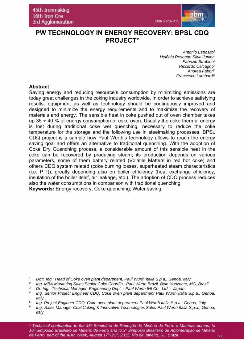
At the end of the distillation process, the hot coke, at a temperature of 1000÷1050 °C is pushed out of the oven furnace and has to be cooled down before further treatments and storage. By mean of the Coke Transfer Car (CTC) the pushed hot coke is discharged into the Coke Quenching Car (CQC) and sent to the cooling system. The installation of a wet quenching plant allows the COB to work also without the CDQ plant in emergency or during maintenance of the plant; the CDQ unit is designed in any case to receive and to manage all the coke production during normal operation with a production rate of 130 tph. Here below the general layout of the plant is shown (Figure 1)
556
ISSN 2176-3135
* Technical contribution to the 45º Seminário de Redução de Minério de Ferro e Matérias-primas, to 16º Simpósio Brasileiro de Minério de Ferro and to 3º Simpósio Brasileiro de Aglomeração de Minério de Ferro, part of the ABM Week, August 17th-21st, 2015, Rio de Janeiro, RJ, Brazil.
Figure 1 - BPSL Layout
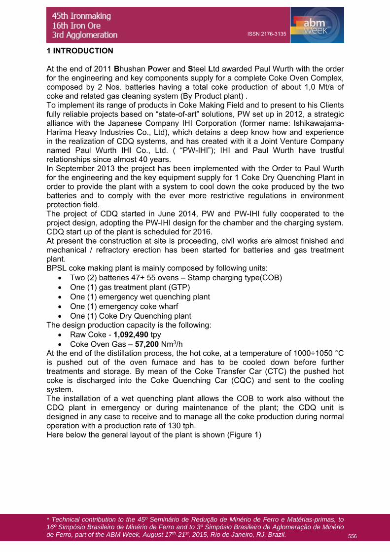
2 QUENCHING PROCESS DESCRIPTION Coke Quenching is done in two ways, traditionally by Wet Quenching and more environment friendlier way by Dry Quenching. 2.1 Wet Quenching The hot coke pushed into a quenching car is sent to the quenching tower, a concrete building with an internal stack, a wide steam outlet area, in order to get low outlet speed for steam and therefore a low dust output. In the upper section of the stack a coke dust capture device made with a system of plastic baffles and the relevant washing system is foreseen.
Figure 2 - Wet quenching concept
The hot coke is quenched for 2-3 minutes under the top nozzles, receiving a water flow of about 2 mc for each ton of coke; the cooling effect is due both to partial evaporation of the water both to temperature increase of the residual water, collected
557
ISSN 2176-3135
* Technical contribution to the 45º Seminário de Redução de Minério de Ferro e Matérias-primas, to 16º Simpósio Brasileiro de Minério de Ferro and to 3º Simpósio Brasileiro de Aglomeração de Minério de Ferro, part of the ABM Week, August 17th-21st, 2015, Rio de Janeiro, RJ, Brazil.
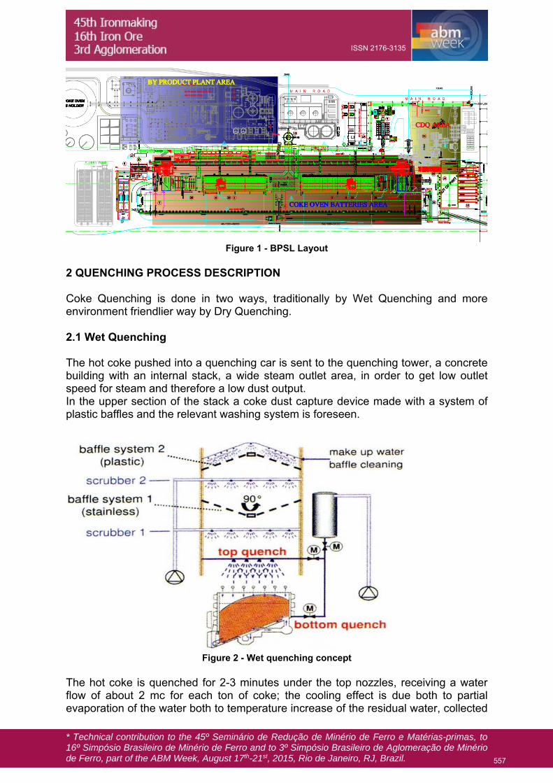
below the charging tower and sent to a settlin basin. Dedicated pumps will take the cooling water, coming from the settling basin, up to the tanks in the quenching tower. Because of this water partially evaporates during coke cooling, there is a level switch in the settling basin that opens a valve installed in the industrial water line for the refilling The settling basin is equipped with grab crane for coke dust removal. Coke boxes are provided for removal of the remained dust in the water. 2.2 Dry Quenching The basic principle of Coke Dry Quenching (“CDQ” for short) is to use cold circulation gas to directly exchange heat with red hot coke in CDQ chamber for coke. The following figure (figure 3) shows a schematic concept of the dry quenching system.
Figure 3 - CDQ Basic Principle
The red hot coke, pushed out of coke oven chamber at a temperature of 950 ÷ 1050 °C, falls into the a special coke bucket positioned on the coke bucket transfer car. The coke bucket car is then hauled by an electric locomotive to the hoisting bay of the CDQ plant: here the coke bucket is blocked by APS system, an hydraulic device that stop the bucket in the proper position and start the charging sequence. The bucket is hooked and lifted by the bucket hoisting crane up to the top of CDQ chamber. The crane moves the bucket up to the final position above the CDQ chamber where it is discharged on the top of the charging system. The charging system is made by a fixed bucket support and a movable hopper: immediately before the bucket reaches the CDQ chamber, an electrical drive removes the CDQ chamber lid replacing it with the movable hopper. By means of the charging device coke is unloaded into the CDQ pre-chamber where it is stored and starts his descending to the cooling chamber proper. In the CDQ chamber the coke slowly descending to the bottom of the chamber, exchanges heat in counter flow directly with circulation gas and is cooled down to below 180 °C.
558
ISSN 2176-3135

* Technical contribution to the 45º Seminário de Redução de Minério de Ferro e Matérias-primas, to 16º Simpósio Brasileiro de Minério de Ferro and to 3º Simpósio Brasileiro de Aglomeração de Minério de Ferro, part of the ABM Week, August 17th-21st, 2015, Rio de Janeiro, RJ, Brazil.
The cooled coke is then unloaded by the discharging device onto the belt conveyor by which coke is sent to the coke screening system. The recirculation of inert gas is provided by the gas circulating circuit where the main fan blows it in the bottom part of the CDQ chamber, at a temperature of 140 °C: via the blasting head device positioned above the discharging cone, the gas is distributed into CDQ chamber where, exchanging heat with the coke, increases its temperature up to 700-800 °C before to be collected through the sloping flues in the external part of the pre-chamber and sent to the primary dust catcher (PDC). Crossing the coke bed in the CDQ chamber, the circulation gas collects the fine dust of the coke and the residual volatiles matters of the coke, together with some CO produced by gasification reactions (the Coke loss of dry quenching process). In the sloping flue area, before the primary DC the excess combustible gas components (CO and hydrogen) are burned with fresh air and the gas temperature rises up to max. 980 °C, before entering the boiler.
Figure 4 - Heat Balance of CDQ
Into the primary dust catcher the content of coke breeze dragged by the gas is reduced removing the coarser portion by settling before entering the boiler. This primary dust removal step is realized by a special design of primary dust catcher adopted in order to optimize the gas distribution at boiler inlet and to increase the lifetime of boiler super-heater piping. In the boiler the gas transfers its heat to the feeding water, generating steam which can be used for electrical energy production or merged into the steam pipe network of the plant. The circulating gas from the boiler is then dedusted via the second dust removal step, usually through a cyclone or multi-cyclone system.
559
ISSN 2176-3135
* Technical contribution to the 45º Seminário de Redução de Minério de Ferro e Matérias-primas, to 16º Simpósio Brasileiro de Minério de Ferro and to 3º Simpósio Brasileiro de Aglomeração de Minério de Ferro, part of the ABM Week, August 17th-21st, 2015, Rio de Janeiro, RJ, Brazil.
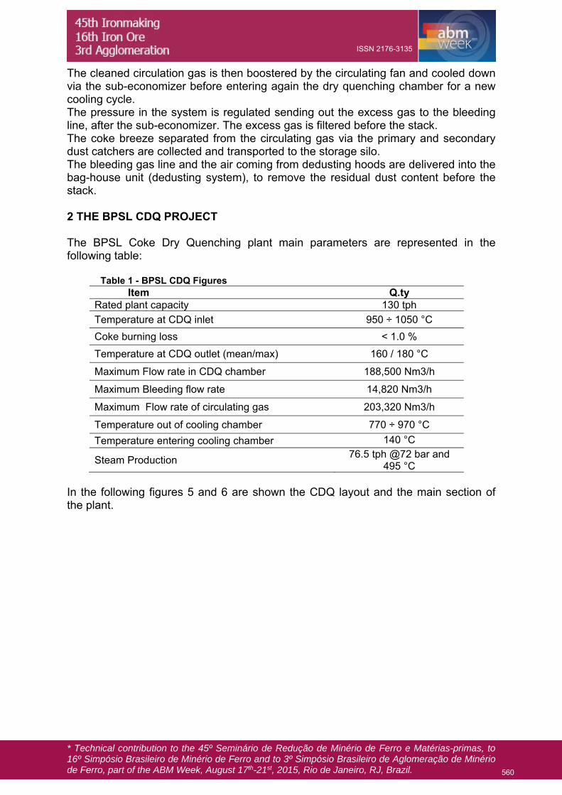
The cleaned circulation gas is then boostered by the circulating fan and cooled down via the sub-economizer before entering again the dry quenching chamber for a new cooling cycle. The pressure in the system is regulated sending out the excess gas to the bleeding line, after the sub-economizer. The excess gas is filtered before the stack. The coke breeze separated from the circulating gas via the primary and secondary dust catchers are collected and transported to the storage silo. The bleeding gas line and the air coming from dedusting hoods are delivered into the bag-house unit (dedusting system), to remove the residual dust content before the stack. 2 THE BPSL CDQ PROJECT The BPSL Coke Dry Quenching plant main parameters are represented in the following table: Table 1 - BPSL CDQ Figures
Item Q.ty Rated plant capacity 130 tph
Temperature at CDQ inlet 950 ÷ 1050 °C
Coke burning loss < 1.0 %
Temperature at CDQ outlet (mean/max) 160 / 180 °C
Maximum Flow rate in CDQ chamber 188,500 Nm3/h
Maximum Bleeding flow rate 14,820 Nm3/h
Maximum Flow rate of circulating gas 203,320 Nm3/h
Temperature out of cooling chamber 770 ÷ 970 °C
Temperature entering cooling chamber 140 °C
Steam Production 76.5 tph @72 bar and
495 °C In the following figures 5 and 6 are shown the CDQ layout and the main section of the plant.
560
ISSN 2176-3135
* Technical contribution to the 45º Seminário de Redução de Minério de Ferro e Matérias-primas, to 16º Simpósio Brasileiro de Minério de Ferro and to 3º Simpósio Brasileiro de Aglomeração de Minério de Ferro, part of the ABM Week, August 17th-21st, 2015, Rio de Janeiro, RJ, Brazil.
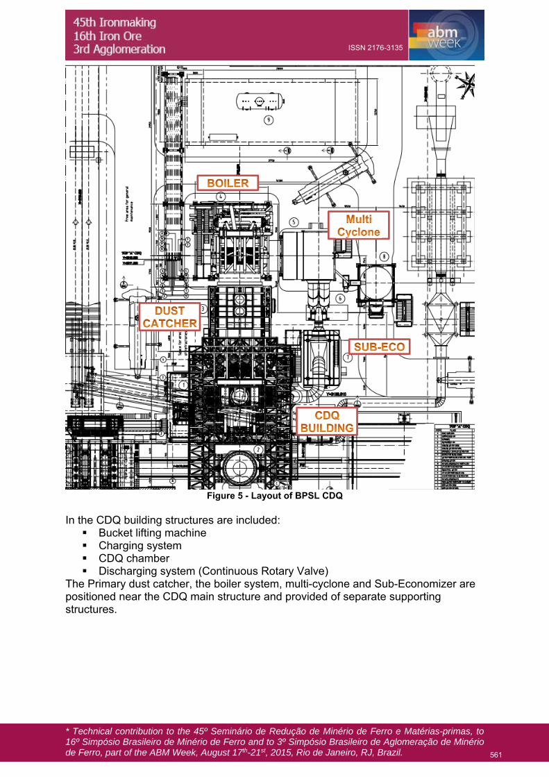
Figure 5 - Layout of BPSL CDQ
In the CDQ building structures are included: Bucket lifting machine Charging system CDQ chamber Discharging system (Continuous Rotary Valve)
The Primary dust catcher, the boiler system, multi-cyclone and Sub-Economizer are positioned near the CDQ main structure and provided of separate supporting structures.
561
ISSN 2176-3135
* Technical contribution to the 45º Seminário de Redução de Minério de Ferro e Matérias-primas, to 16º Simpósio Brasileiro de Minério de Ferro and to 3º Simpósio Brasileiro de Aglomeração de Minério de Ferro, part of the ABM Week, August 17th-21st, 2015, Rio de Janeiro, RJ, Brazil.
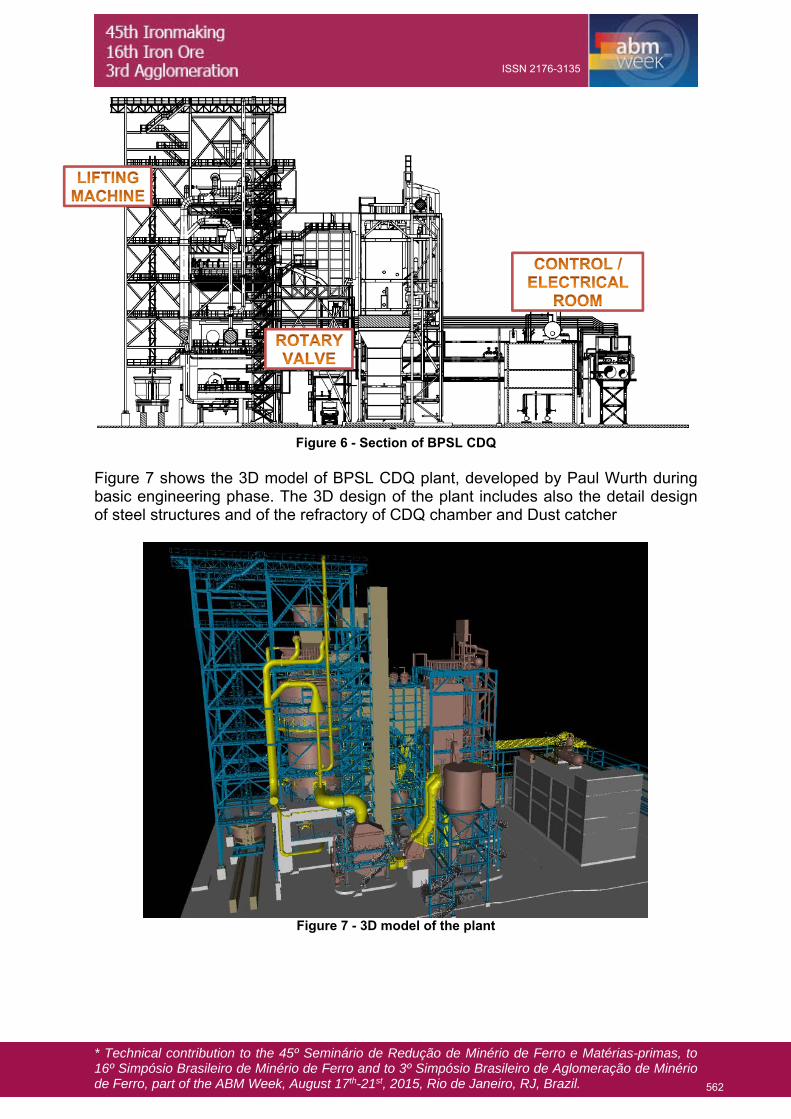
Figure 6 - Section of BPSL CDQ
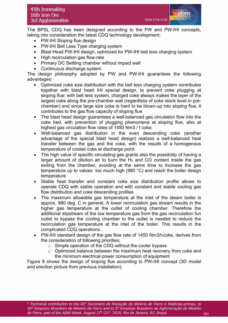
Figure 7 shows the 3D model of BPSL CDQ plant, developed by Paul Wurth during basic engineering phase. The 3D design of the plant includes also the detail design of steel structures and of the refractory of CDQ chamber and Dust catcher
Figure 7 - 3D model of the plant
562
ISSN 2176-3135
* Technical contribution to the 45º Seminário de Redução de Minério de Ferro e Matérias-primas, to 16º Simpósio Brasileiro de Minério de Ferro and to 3º Simpósio Brasileiro de Aglomeração de Minério de Ferro, part of the ABM Week, August 17th-21st, 2015, Rio de Janeiro, RJ, Brazil.
The BPSL CDQ has been designed according to the PW and PW-IHI concepts, taking into consideration the latest CDQ technology development:
PW-IHI Sloping flue design PW-IHI Bell Less Type charging system Blast Head PW-IHI design, optimized for PW-IHI bell less charging system High recirculation gas flow-rate Primary DC Settling chamber without impact wall Continuous discharge system
The design philosophy adopted by PW and PW-IHI guarantees the following advantages:
Optimized coke size distribution with the bell less charging system contributes together with blast head IHI special design, to prevent coke plugging at sloping flue; with bell less system, charged coke always makes the layer of the largest coke along the pre-chamber wall (regardless of coke stock level in pre-chamber) and since large size coke is hard to be blown-up into sloping flue, it contributes to the gas flow capacity of sloping flue
The blast head design guarantees a well-balanced gas circulation flow into the coke bed, with prevention of plugging phenomena at sloping flue, also at highest gas circulation flow rates of 1450 Nm3 / t coke;
Well-balanced gas distribution in the even descending coke (another advantage of the special blast head design) realizes a well-balanced heat transfer between the gas and the coke, with the results of a homogenous temperature of cooled coke at discharge point.
The high value of specific circulating gas grants also the possibility of having a larger amount of dilution air to burn the H2 and CO content inside the gas exiting from the chamber, avoiding at the same time to increase the gas temperature up to values too much high (980 °C) and reach the boiler design temperature
Stable heat transfer and constant coke size distribution profile allows to operate CDQ with stable operation and with constant and stable cooling gas flow distribution and coke descending profiles
The maximum allowable gas temperature at the inlet of the steam boiler is approx. 980 deg. C in general. A lower recirculation gas stream results in the higher gas temperature at the outlet of cooling chamber. Therefore the additional slipstream of the low temperature gas from the gas recirculation fun outlet to bypass the cooling chamber to the outlet is needed to reduce the recirculation gas temperature at the inlet of the boiler. This results in the complicated CDQ operations.
PW-IHI standard design of the gas flow rate of 1450 Nm3/t-coke, derives from the consideration of following priorities;
o Simple operation of the CDQ without the cooler bypass o Optimized balance between the maximum heat recovery from coke and
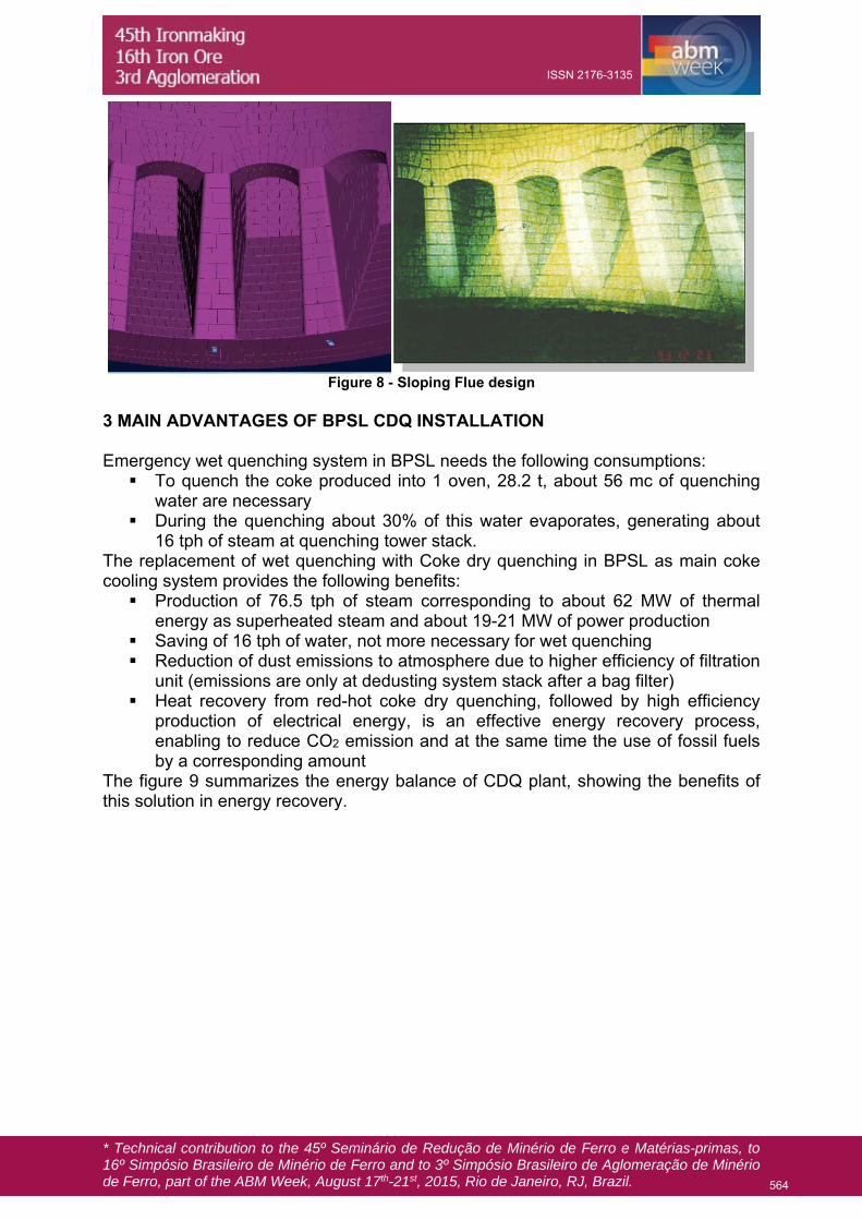
the minimum electrical power consumption of equipment Figure 8 shows the design of sloping flue according to PW-IHI concept (3D model and erection picture from previous installation).
563
ISSN 2176-3135
* Technical contribution to the 45º Seminário de Redução de Minério de Ferro e Matérias-primas, to 16º Simpósio Brasileiro de Minério de Ferro and to 3º Simpósio Brasileiro de Aglomeração de Minério de Ferro, part of the ABM Week, August 17th-21st, 2015, Rio de Janeiro, RJ, Brazil.
Figure 8 - Sloping Flue design
3 MAIN ADVANTAGES OF BPSL CDQ INSTALLATION Emergency wet quenching system in BPSL needs the following consumptions: To quench the coke produced into 1 oven, 28.2 t, about 56 mc of quenching
water are necessary During the quenching about 30% of this water evaporates, generating about
16 tph of steam at quenching tower stack. The replacement of wet quenching with Coke dry quenching in BPSL as main coke cooling system provides the following benefits: Production of 76.5 tph of steam corresponding to about 62 MW of thermal
energy as superheated steam and about 19-21 MW of power production Saving of 16 tph of water, not more necessary for wet quenching Reduction of dust emissions to atmosphere due to higher efficiency of filtration
unit (emissions are only at dedusting system stack after a bag filter) Heat recovery from red-hot coke dry quenching, followed by high efficiency
production of electrical energy, is an effective energy recovery process, enabling to reduce CO2 emission and at the same time the use of fossil fuels by a corresponding amount
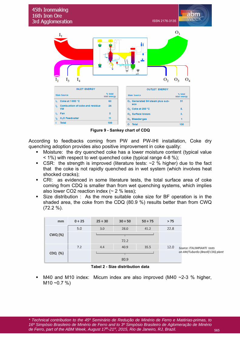
The figure 9 summarizes the energy balance of CDQ plant, showing the benefits of this solution in energy recovery.
564
ISSN 2176-3135
* Technical contribution to the 45º Seminário de Redução de Minério de Ferro e Matérias-primas, to 16º Simpósio Brasileiro de Minério de Ferro and to 3º Simpósio Brasileiro de Aglomeração de Minério de Ferro, part of the ABM Week, August 17th-21st, 2015, Rio de Janeiro, RJ, Brazil.
Figure 9 - Sankey chart of CDQ
According to feedbacks coming from PW and PW-IHI installation, Coke dry quenching adoption provides also positive improvement in coke quality: Moisture: the dry quenched coke has a lower moisture content (typical value
< 1%) with respect to wet quenched coke (typical range 4-8 %); CSR: the strength is improved (literature tests: ~2 % higher) due to the fact
that the coke is not rapidly quenched as in wet system (which involves heat shocked cracks);
CRI: as evidenced in some literature tests, the total surface area of coke coming from CDQ is smaller than from wet quenching systems, which implies also lower CO2 reaction index (~ 2 % less);
Size distribution : As the more suitable coke size for BF operation is in the shaded area, the coke from the CDQ (80.9 %) results better than from CWQ (72.2 %).
Tabel 2 - Size distribution data
M40 and M10 index: Micum index are also improved (M40 ~2-3 % higher,
M10 ~0.7 %)
565
ISSN 2176-3135