ptb 01 atex 2175€¦ · ptb ex-95.d.2160 ptb 01 atex 2175 eex ia iic t6 ii 2 g eex ia iic t5 or t6...
TRANSCRIPT

Operating Instructions
BedienungsanleitungInstructions de Service
PTB 01 ATEX 2175
Device with II 2G EEx i-approvalGeräte mit II 2G EEx i-Zulassung
Appareils avec mode de protection II 2G EEx i
Example/Beispiel/Exemple Type 6106

We reserve the right to make technical changes without notice.Technische Änderungen vorbehalten.Sous resérve de modification techniques.
© 2002 Bürkert Werke GmbH & Co. KG
Operating Instructions 0507/09_EU-ML_00804563
old new
PTB Ex-95.D.2160 PTB 01 ATEX 2175
EEx ia IIC T6 II 2 G EEx ia IIC T5 or T6
CE CE0102
alt neu
PTB Ex-95.D.2160 PTB 01 ATEX 2175
EEx ia IIC T6 II 2 G EEx ia IIC T5 oder T6
CE CE0102
ancien nouveau
PTB Ex-95.D.2160 PTB 01 ATEX 2175
EEx ia IIC T6 II 2 G EEx ia IIC T5 ou T6
CE CE0102
Homologation ATEXDepuis le 01. 07. 2003 la nouvelle directive CE 94/9/CE (ATEX 100a) est appliquée. Leprésent produit Bürkert correspond aux exigences de cette directive. Comparé àl'homologation existante jusqu'à maintenant, seul le marquage a changé, les appareils sonttechniquement identiques.
Les identification se différencientcomme suit:
ATEX-ZulassungSeit dem 01. 07. 2003 wird die neue EG-Richtlinie 94/9/EG (ATEX 100a) angewendet. Dasvorliegende Bürkert-Produkt entspricht den Anforderungen dieser Richtlinie. Im Vergleichzur bisherigen Zulassung hat sich nur die Kennzeichnung geändert, technisch sind dieGeräte identisch.
Die Kennzeichnungen unterscheidensich wie folgt:
ATEX ApprovalSince 01.07.2003, the new EC Guideline 94/9/EC (ATEX 100a) is being applied. Thepresent Bürkert product complies with the requirements of this Guideline. Compared withthe previous approval, only the marking has changed; the devices are technically identical.
The markings will change as follows:

01 ATEX 2175 - 1
eng
lish
Devices with II 2G EEx i approvalPTB 01 ATEX 2175
EC CONFORMITY DECLARATION .................................................................. 2
GENERAL NOTES ........................................................................................................................ 3
Intended use ............................................................................................................................................... 3
Safety notes ............................................................................................................................................... 4
OPERATING CONDITIONS OF THE COILS ........................................ 5
TECHNICAL DATA ...................................................................................................................... 6
General notes on the technical data of the device ............................................... 6
Electrical data ........................................................................................................................................... 7
ASSEMBLY AND COMMISSIONING .......................................................... 10
MALFUNCTIONS, MAINTENANCE AND REPAIRS ......... 12
Malfunctions ............................................................................................................................................12
Maintenance and repairs ........................................................................................................... 12
ANNEX
EC Design Test Certificate ........................................................................................................37
2 - 01 ATEX 2175
eng
lish
As manufacturer, Bürkert Werke GmbH & Co. KG herewith declares that theseproducts comply with the requirements of the Directives of the Committee for theHarmonization of the Legal Regulations of Member States concerning
• in respect of electromagnetic compatibility (89/1336/EWG)
• equipment and protective systems intended for use in potentially explosiveatmospheres (ATEX, 94/9/EU).
For the assessment of the products in respect of electromagnetic compatibility, thefollowing standards were applied:
EN 50081-2: 03/94 Basic engineering standard for interferenceemission;
Part 2: Industrial domain
EN 61000-6-2: 03/00 Basic engineering standard for interferenceresistance;
Part 2: Industrial domain
The following standards were consulted with resprect to the compliance with theATEX-Directives:
EN 50014: 1997+A1+A2 Electrical apparatus for potentially explosiveatmospheres. General requirements
EN 50020: 1994 Electrical apparatus for potentially explosiveatmospheres. Intrinsic safety „i“
Ingelfingen, 08.03.2004 Otto WalchPlace and date Certifications Manager
EC CONFORMITY DECLARATION
01 ATEX 2175 - 3
eng
lish
Intended use
Please observe the notes in these operating instructions as well as theconditions of use and permitted data specified on the data sheet of the device inuse, in order that the device will function perfectly and have a long service life.
• On non-observance of these notes and unauthorized interference with thedevice, we will refuse all liability and the guarantee on device andaccessories will become void!
• The device serves exclusively as a solenoid valve for the media stated inthe data sheet and for use in Explosion Group II, Category 2 G and
Temperature Class T5 or T6 (see data on the approval plate).
• The type of protection used is inherent safety EEx i for coils with circularconnectors, rectangular connectors with and without protective collars, aswell as connection via single impressed wires and apparatus socketconnection upwards to DIN 43650 Form C.
• The device may be employed in potentially explosive atmospheres only inthe manner approved by the Physikalisch Technische Bundesanstalt, i.e. thevalues stated in the approval or the electrical connection shall be compliedwith.
• Any other use or use exceeding the specific scope is considered to be non-intended use. Bürkert will not be liable for any damage resulting therefrom.The risk will be borne by the user.
NOTE For EC Design Test Certificate PTB 01 ATEX 2175,see annex. For temperature classes and electrical data see"Technical Data".
The EC Design Type Inspection Certificate PTB 01 ATEX 2175
was issued and the production audited (CE0102) by the
Physikalisch Technischen Bundesanstalt
Bundesallee 100
38116 Braunschweig
GENERAL NOTES
4 - 01 ATEX 2175
eng
lish
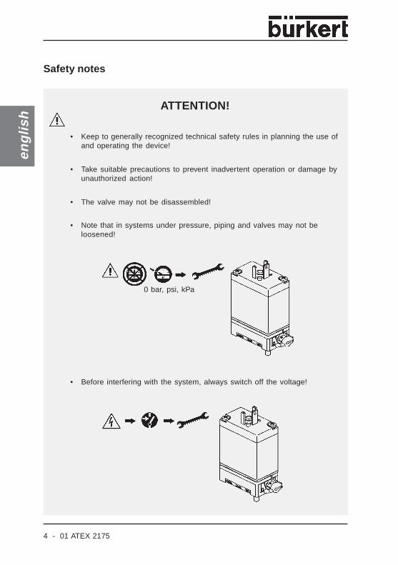
• Before interfering with the system, always switch off the voltage!
ATTENTION!
0 bar, psi, kPa
Safety notes
• Keep to generally recognized technical safety rules in planning the use ofand operating the device!
• Take suitable precautions to prevent inadvertent operation or damage byunauthorized action!
• The valve may not be disassembled!
• Note that in systems under pressure, piping and valves may not beloosened!

01 ATEX 2175 - 5
eng
lish
OPERATING CONDITIONS OF THE COILS
1. Individual assembly / Block assembly
The solenoids Type AC 21 are suitable for individual and block assembly (see„Electrical data“).
2. Operating temperature range
Observe the operating temperature range for each type given in „Electrical data“.

6 - 01 ATEX 2175
eng
lish
General notes on the technical data of the device
ATTENTION!
The technical data given on the rating plate of each device shall not be exceeded!
TECHNICAL DATA
Example
PTB certification No.
Space for barcodeIdent. no / date of productionSerial no. of the coil /CE designationAmbient temperatureVoltage (±10 %) - power ratingMode of protection/temperature codeCoil type - port size for fluid part - coil size
01 ATEX 2175 - 7
eng
lish
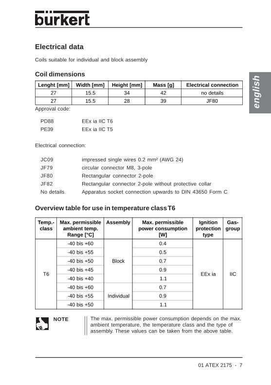
Electrical data
Coils suitable for individual and block assembly
Coil dimensions
Approval code:
PD88 EEx ia IIC T6
PE39 EEx ia IIC T5
Electrical connection:
JC09 impressed single wires 0.2 mm² (AWG 24)
JF79 circular connector M8, 3-pole
JF80 Rectangular connector 2-pole
JF82 Rectangular connector 2-pole without protective collar
No details Apparatus socket connection upwards to DIN 43650 Form C
Overview table for use in temperature class T6
NOTE The max. permissible power consumption depends on the max.ambient temperature, the temperature class and the type ofassembly. These values can be taken from the above table.
Temp.-class
Max. permissibleambient temp.
Range [°C]
Assembly Max. permissiblepower consumption
[W]
Ignitionprotection
type
Gas-group
T6
-40 bis +60
Block
0.4
EEx ia IIC
-40 bis +55 0.5
-40 bis +50 0.7
-40 bis +45 0.9
-40 bis +40 1.1
-40 bis +60
Individual
0.7
-40 bis +55 0.9
-40 bis +50 1.1
Lenght [mm] Width [mm] Height [mm] Mass [g] Electrical connection
27 15.5 34 42 no details
27 15.5 28 39 JF80
8 - 01 ATEX 2175
eng
lish
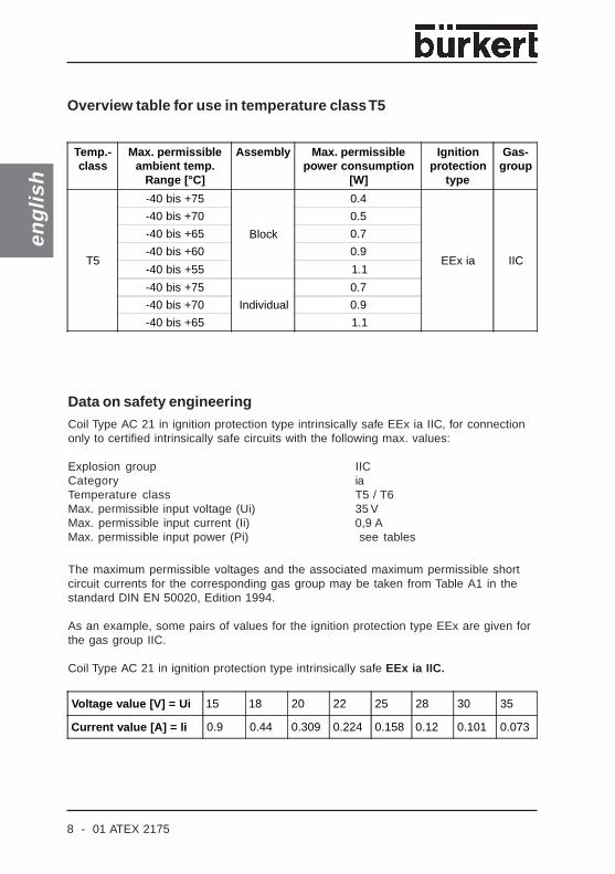
Overview table for use in temperature class T5
Data on safety engineeringCoil Type AC 21 in ignition protection type intrinsically safe EEx ia IIC, for connectiononly to certified intrinsically safe circuits with the following max. values:
Explosion group IICCategory iaTemperature class T5 / T6Max. permissible input voltage (Ui) 35 VMax. permissible input current (Ii) 0,9 AMax. permissible input power (Pi) see tables
The maximum permissible voltages and the associated maximum permissible shortcircuit currents for the corresponding gas group may be taken from Table A1 in thestandard DIN EN 50020, Edition 1994.
As an example, some pairs of values for the ignition protection type EEx are given forthe gas group IIC.
Coil Type AC 21 in ignition protection type intrinsically safe EEx ia IIC.
Temp.-class
Max. permissibleambient temp.
Range [°C]
Assembly Max. permissiblepower consumption
[W]
Ignitionprotection
type
Gas-group
T5
-40 bis +75
Block
0.4
EEx ia IIC
-40 bis +70 0.5
-40 bis +65 0.7
-40 bis +60 0.9
-40 bis +55 1.1
-40 bis +75
Individual
0.7
-40 bis +70 0.9
-40 bis +65 1.1
Voltage value [V] = Ui 15 18 20 22 25 28 30 35
Current value [A] = li 0.9 0.44 0.309 0.224 0.158 0.12 0.101 0.073
01 ATEX 2175 - 9
eng
lish
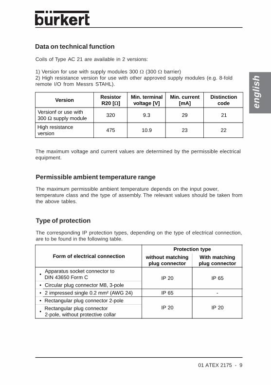
Data on technical function
Coils of Type AC 21 are available in 2 versions:
1) Version for use with supply modules 300 Ω (300 Ω barrier)2) High resistance version for use with other approved supply modules (e.g. 8-foldremote I/O from Messrs STAHL).
The maximum voltage and current values are determined by the permissible electricalequipment.
Permissible ambient temperature range
The maximum permissible ambient temperature depends on the input power,temperature class and the type of assembly. The relevant values should be taken fromthe above tables.
The corresponding IP protection types, depending on the type of electrical connection,are to be found in the following table.
Type of protection
VersionResistorR20 [Ω]
Min. terminalvoltage [V]
Min. current[mA]
Distinctioncode
Versionf or use with300 Ω supply module
320 9.3 29 21
High resistanceversion
475 10.9 23 22
Form of electrical connectionProtection type
without matchingplug connector
With matchingplug connector
•Apparatus socket connector toDIN 43650 Form C IP 20 IP 65
• Circular plug connector M8, 3-pole
• 2 impressed single 0.2 mm² (AWG 24) IP 65 -
• Rectangular plug connector 2-poleIP 20 IP 20
•Rectangular plug connector2-pole, without protective collar

10 - 01 ATEX 2175
eng
lish
flow dire
ction
Clean piping
Any orientation of installation
preferred
direction
Attach filter upstream
ASSEMBLY AND COMMISSIONING
Assembly
Coils of Type AC 21 are suitable for individual and block assembly, depending on theinput power, temperature class and ambient temperature.

01 ATEX 2175 - 11
eng
lish
Fluidic connection
Assembly/disassembly
The device may not be disassembled!
Types of connection
Rectangular plugconnector with or withoutprotective collar
2 individual wires Circular plugconnector Apparatus socket
connector upwards toDIN 43650 Form C
0 bar, psi, kpa

12 - 01 ATEX 2175
eng
lish
Malfunctions
Pressure
Polarity
For proper functioning, thecorresponding connection ismarked on the plug flag with „+“,.
bar, psi, kPa
Piping
In case of malfunction, check:
Voltage
Maintenance and repair
The coils are maintenance free when operated under the conditions described inthese operating instructions.
As a general rule, have repairs made by the manufacturer!
The valve may not be opened during repair or maintenance work on theinstallation!
ATTENTION!
MALFUNCTIONS, MAINTENANCE AND REPAIRS
01 ATEX 2175 - 13
deu
tsch
Geräte mit II 2G EEx i-ZulassungPTB 01 ATEX 2175
EG-KONFORMITÄTSERKLÄRUNG ........................................................... 14
ALLGEMEINE HINWEISE ............................................................................................. 15
Bestimmungsgemäße Verwendung ...................................................................................15
Sicherheitshinweise ..........................................................................................................................16
EINSATZBEDINGUNGEN DER SPULEN .......................................... 17
TECHNISCHE DATEN ....................................................................................................... 18
Allgemeine Hinweise zu den technischen Datendes Gerätes ..............................................................................................................................................18
Elektrische Daten ...............................................................................................................................19
MONTAGE UND INBETRIEBNAHME ....................................................... 22
STÖRUNGEN, WARTUNG UND REPARATUREN .............. 24
Strörungen .................................................................................................................................................24
Wartung und Reparaturen ......................................................................................................... 24
ANHANG
EG-Baumusterprüfbescheinigung .......................................................................................37

14 - 01 ATEX 2175
deu
tsch
Hiermit erklärt die Firma Bürkert Werke GmbH & Co. KG als Hersteller, dass dieseErzeugnisse den Anforderungen entsprechen, die in den Richtlinien des Rates zurAngleichung der Rechtsvorschriften der Mitgliedstaaten über
• die elektromagnetische Verträglichkeit (89/1336/EWG)
• und für Geräte und Schutzsysteme zur bestimmungsgemäßen Verwendung inexplosionsgefährdeten Bereichen (ATEX, 94/9EG) festgelegt sind.
Zur Beurteilung der Erzeugnisse hinsichtlich der elektromagnetischen Verträglich-keit wurden folgende Normen herangezogen:
EN 50081-2: 03/94 Fachgrundnorm Störaussendung;
Teil 2: Industriebereich
EN 61000-6-2: 03/00 Fachgrundnorm Störfestigkeit;
Teil 2: Industriebereich
Zur Beurteilung der Erzeugnisse hinsichtlich der ATEX-Richtlinie wurden folgendeNormen herangezogen:
EN 50014: 1997+A1+A2 Elektrische Betriebsmittel für explosions -gefährdete Bereiche,Allgemeine Bestimmungen
EN 50020: 1994 Elektrische Betriebsmittel für explosions -gefährdete Bereiche,Eigensicherheit "i"
EG - KONFORMITÄTSERKLÄRUNG
Ingelfingen, 08.03.2004 Otto WalchOrt und Datum Certifications Manager

01 ATEX 2175 - 15
deu
tsch
Bestimmungsgemäße Verwendung
Bitte beachten Sie die Hinweise dieser Betriebsanleitung sowie die Einsatzbedingungen und zulässigen Daten gemäß Datenblatt des eingesetzten Gerä-tes, damit es einwandfrei funktioniert und lange einsatzfähig bleibt.
• Bei Nichtbeachtung dieser Hinweise sowie bei unzulässigen Eingriffen in dasGerät entfällt jegliche Haftung unsererseits, ebenso erlischt die Garantie aufGeräte u. Zubehörteile!
• Das Gerät dient ausschließlich als Magnetventil für die lt. Datenblattzulässigen Medien und für den Einsatz in Explosionsgruppe II,Kategorie 2 G und Temperaturklasse T5 oder T6 (siehe Angaben auf dem
-Zulassungsschild).
• Die angewandte Schutzart ist die Eigensicherheit EEx i für Spulen mitRundsteckeranschluss, Rechtecksteckeranschluss mit und ohneSchutzkragen sowie Anschluss über eingepresste Einzellitzen undGerätesteckdosenanschluss nach oben gemäß DIN 43650 Form C.
• Das Gerät darf in explosionsgefährdeter Atmosphäre nur in der von derPysikalisch-Technischen Bundesanstalt genehmigten Weise eingesetztwerden, d.h. die in der Zulasssung aufgeführten Werte bzw. die elektrischeBeschaltung ist einzuhalten.
• Eine andere oder darüber hinausgehende Benutzung gilt als nichtbestimmungsgemäß. Für hieraus resultierende Schäden haftet Bürkertnicht. Das Risiko trägt allein der Anwender.
HINWEIS Die Baumusterprüfbescheinigung PTB 01 ATEX 2175 finden Sieim Anhang. Temperaturklassen und elektrische Daten siehe"Technische Daten".
Die EG-Baumusterprüfbescheinigung PTB 01 ATEX 2175
wurde von der
Physikalisch Technischen Bundesanstalt
Bundesallee 100
38116 Braunschweig
ausgestellt, die auch die Fertigung auditiert (CE0102).
ALLGEMEINE HINWEISE
16 - 01 ATEX 2175
deu
tsch
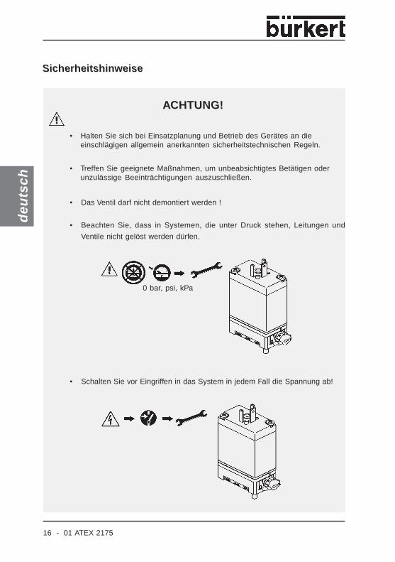
• Schalten Sie vor Eingriffen in das System in jedem Fall die Spannung ab!
ACHTUNG!
0 bar, psi, kPa
Sicherheitshinweise
• Halten Sie sich bei Einsatzplanung und Betrieb des Gerätes an dieeinschlägigen allgemein anerkannten sicherheitstechnischen Regeln.
• Treffen Sie geeignete Maßnahmen, um unbeabsichtigtes Betätigen oderunzulässige Beeinträchtigungen auszuschließen.
• Das Ventil darf nicht demontiert werden !
• Beachten Sie, dass in Systemen, die unter Druck stehen, Leitungen und
Ventile nicht gelöst werden dürfen.
01 ATEX 2175 - 17
deu
tsch
EINSATZBEDINGUNGEN DER SPULEN
1. Einzelmontage / Blockmontage
Die Magnetspulen Typ AC 21 sind für Einzel- und Blockmontage geeignet (siehe "Elek-trische Daten").
2. Einsatztemperaturbereich
Beachten Sie für jeden Typ den bei den „Elektrischen Daten“ aufgeführten Einsatz-temperaturbereich!

18 - 01 ATEX 2175
deu
tsch
Allgemeine Hinweise zu den technischen Daten des Gerätes
ACHTUNG!
Die auf dem Typschild des jeweiligen Gerätes angegebenen technischen Datendürfen nicht überschritten werden!
TECHNISCHE DATEN
Beispiel
Platz für BarcodeIdent-Nr. der Spule - HerstelldatenSerien-Nr. der Spule - CE-Kenn-zeichnungUmgebungstemperaturSpannung (±10 %) - LeistungSchutzart/TemperaturklasseSpulentyp - Anschlussgröße fürFluidteil -Spulengröße
PTB-Zulassungsnummer
01 ATEX 2175 - 19
deu
tsch
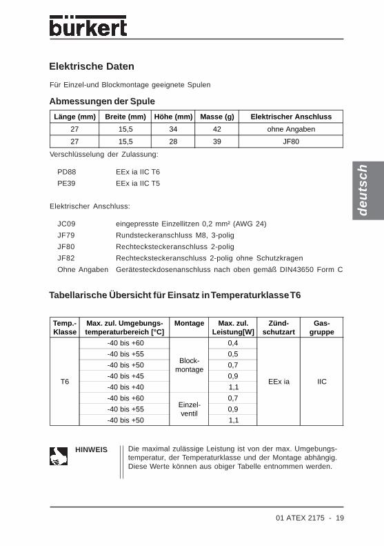
Elektrische Daten
Für Einzel-und Blockmontage geeignete Spulen
Abmessungen der Spule
Verschlüsselung der Zulassung:
PD88 EEx ia IIC T6
PE39 EEx ia IIC T5
Elektrischer Anschluss:
JC09 eingepresste Einzellitzen 0,2 mm² (AWG 24)
JF79 Rundsteckeranschluss M8, 3-polig
JF80 Rechtecksteckeranschluss 2-polig
JF82 Rechtecksteckeranschluss 2-polig ohne Schutzkragen
Ohne Angaben Gerätesteckdosenanschluss nach oben gemäß DIN43650 Form C
Tabellarische Übersicht für Einsatz in Temperaturklasse T6
HINWEIS Die maximal zulässige Leistung ist von der max. Umgebungs-temperatur, der Temperaturklasse und der Montage abhängig.Diese Werte können aus obiger Tabelle entnommen werden.
Länge (mm) Breite (mm) Höhe (mm) Masse (g) Elektrischer Anschluss
27 15,5 34 42 ohne Angaben
27 15,5 28 39 JF80
Temp.-Klasse
Max. zul. Umgebungs-temperaturbereich [°C]
Montage Max. zul.Leistung[W]
Zünd-schutzart
Gas-gruppe
T6
-40 bis +60
Block-montage
0,4
EEx ia IIC
-40 bis +55 0,5
-40 bis +50 0,7
-40 bis +45 0,9
-40 bis +40 1,1
-40 bis +60Einzel-ventil
0,7
-40 bis +55 0,9
-40 bis +50 1,1

20 - 01 ATEX 2175
deu
tsch
Tabellarische Übersicht für Einsatz in Temperaturklasse T5
Sicherheitstechnische DatenSpule Typ AC 21 in Zündschutzart Eigensicherheit EEx ia IIC, nur zum Anschluss anbescheinigte eigensichere Stromkreise mit folgenden Höchstwerten:
Explosionsgruppe: IICKategorie: iaTemperaturklasse: T5 / T6Maximal zulässige Eingangsspannung (Ui): 35 VMaximal zulässiger Eingangsstrom (Ii): 0,9 AMaximal zulässige Eingangsleistung (Pi): Siehe Tabellen
Die maximal zulässigen Spannungen und die dazugehörigen maximal zulässigenKurzschlussströme können für die entsprechende Gasgruppe, der Tabelle A1 in derNorm DIN EN 50020 : 1994, entnommen werden.
Beispielhaft sind für die Zündschutzart EEx ia einige Wertepaare für die GasgruppeIIC aufgeführt.
Spule Typ AC 21 in Zündschutzart Eigensicherheit EEx ia IIC.
Temp.-Klasse
Max. zul. Umgebungs-temperaturbereich [°C]
Montage Max. zul.Leistung [W]
Zünd-schutzart
Gas-gruppe
T5
-40 bis +75
Block-montage
0,4
EEx ia IIC
-40 bis +70 0,5
-40 bis +65 0,7
-40 bis +60 0,9
-40 bis +55 1,1
-40 bis +75Einzel-ventil
0,7
-40 bis +70 0,9
-40 bis +65 1,1
Spannungswert [V] = Ui 15 18 20 22 25 28 30 35
Stromwert [A] = li 0,9 0,44 0,309 0,224 0,158 0,12 0,101 0,073
01 ATEX 2175 - 21
deu
tsch
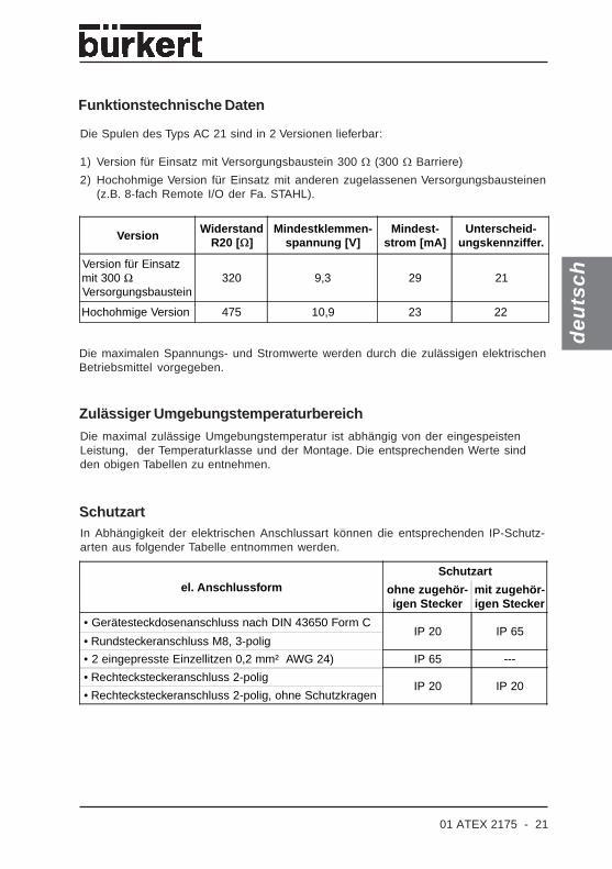
Funktionstechnische Daten
Die Spulen des Typs AC 21 sind in 2 Versionen lieferbar:
1) Version für Einsatz mit Versorgungsbaustein 300 Ω (300 Ω Barriere)
2) Hochohmige Version für Einsatz mit anderen zugelassenen Versorgungsbausteinen(z.B. 8-fach Remote I/O der Fa. STAHL).
Die maximalen Spannungs- und Stromwerte werden durch die zulässigen elektrischenBetriebsmittel vorgegeben.
Zulässiger UmgebungstemperaturbereichDie maximal zulässige Umgebungstemperatur ist abhängig von der eingespeistenLeistung, der Temperaturklasse und der Montage. Die entsprechenden Werte sindden obigen Tabellen zu entnehmen.
In Abhängigkeit der elektrischen Anschlussart können die entsprechenden IP-Schutz-arten aus folgender Tabelle entnommen werden.
Schutzart
Version WiderstandR20 [Ω]
Mindestklemmen-spannung [V]
Mindest-strom [mA]
Unterscheid-ungskennziffer.
Version für Einsatzmit 300 ΩVersorgungsbaustein
320 9,3 29 21
Hochohmige Version 475 10,9 23 22
el. AnschlussformSchutzart
ohne zugehör-igen Stecker
mit zugehör-igen Stecker
• Gerätesteckdosenanschluss nach DIN 43650 Form CIP 20 IP 65
• Rundsteckeranschluss M8, 3-polig
• 2 eingepresste Einzellitzen 0,2 mm² AWG 24) IP 65 ---
• Rechtecksteckeranschluss 2-poligIP 20 IP 20
• Rechtecksteckeranschluss 2-polig, ohne Schutzkragen

22 - 01 ATEX 2175
deu
tsch
Durchflussr
ichtung
Rohrleitungen reinigen
Einbaulage beliebig
Vorzugs-
richtung
Filter vorschalten
MONTAGE UND INBETRIEBNAHME
Montage
Die Magnetspulen des Typs AC 21 sind abhängig von der eingespeisten Leistung, derTemperaturklasse und der Umgebungstemperatur, für Einzel- und Blockmontagegeeignet.

01 ATEX 2175 - 23
deu
tsch
Fluidischer Anschluss
Montage/Demontage
Das Gerät darf nicht demontiert werden!
Anschlussarten
Rechtecksteckermit bzw. ohneSchutzkragen
2 Einzellitzen
Rundstecker
Gerätesteckdosen-anschluss nach obengemäß DIN 43650Form C
0 bar, psi, kpa
24 - 01 ATEX 2175
deu
tsch
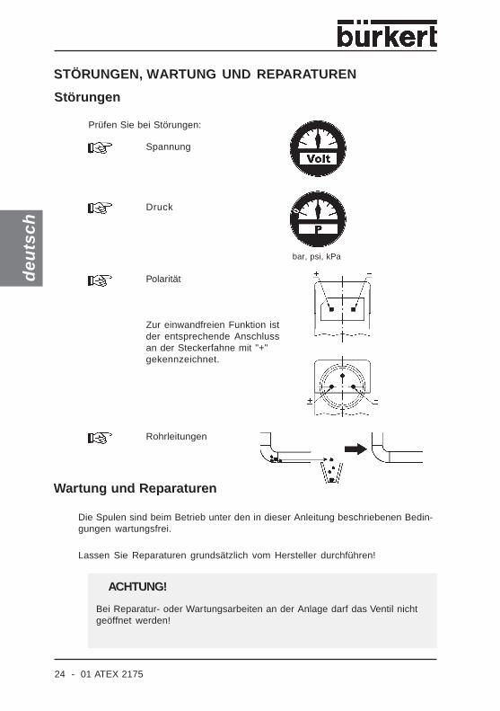
Störungen
Druck
Polarität
Zur einwandfreien Funktion istder entsprechende Anschlussan der Steckerfahne mit "+"gekennzeichnet.
bar, psi, kPa
Rohrleitungen
Prüfen Sie bei Störungen:
Spannung
Wartung und Reparaturen
Die Spulen sind beim Betrieb unter den in dieser Anleitung beschriebenen Bedin-gungen wartungsfrei.
Lassen Sie Reparaturen grundsätzlich vom Hersteller durchführen!
Bei Reparatur- oder Wartungsarbeiten an der Anlage darf das Ventil nichtgeöffnet werden!
ACHTUNG!
STÖRUNGEN, WARTUNG UND REPARATUREN

01 ATEX 2175 - 25
fran
çais
Appareils avec mode deprotection II 2G EEx iPTB 01 ATEX 2175
DÉCLARATION DE CONFORMITÉ CE .................................................. 26
REMARQUES GENERALES ................................................................................... 27
Utilisation conforme aux prescriptions ...........................................................................27
Consignes de sécurité ................................................................................................................... 28
CONDITIONS D'UTILISATION DES BOBINES .......................... 29
CARACTERISTIQUES TECHNIQUES ..................................................... 30
Remarques générales concernant les caractéristiquestechniques de l'appareil ................................................................................................................. 30
Caractéristiques électriques ..................................................................................................... 31
MONTAGE ET MISE EN SERVICE ................................................................. 34
PANNES, MAINTENANCE ET REPARATIONS ....................... 36
Pannes ..........................................................................................................................................................36
Maintenance et réparations ..................................................................................................... 36
ANNEXE
Certificat d’essai de modèle CE ..........................................................................................37
26 - 01 ATEX 2175
fran
çais
DÉCLARATION DE CONFORMITÉ CE
Ingelfingen, 08.03.2004 Otto Walchlieu et date Certifications Manager
En qualité de fabricant, la société Bürkert Werke GmbH & Co. KG déclare que ceproduit est conforme aux prescriptions stipulées dans les directives du Conseilconcernant le rapprochement des législations des Etats membres relatives
• à la compatibilité électromagnétique (89/1336/EWG)
• aux appareils et systèmes de protection destinés à être utilisés en atmosphèresexplosibles (ATEX, 94/9CE).
Les normes suivantes ont été prises en considération pour l’évaluation des produitsen ce qui concerne la compatibilité électromagnétique:
EN 50081-2: 03/94 Norme de base sur les rayonnementsparasites;
Section 2: domaine industriel
EN 61000-6-2: 03/00 Norme de base sur la résistance auxperturbations;
Section 2: domaine industriel
Pour juger les produits par rapport à la directive ATEX, les normes suivantes on étéappliquées.
EN 50014: 1997+A1+A2 Matériel électrique pour atmosphèresexplosibles – Règles générales
EN 50020: 1994 Matériel électrique pour atmosphèresexplosibles – Sécurité aumentée „i“

01 ATEX 2175 - 27
fran
çais
Utilisation conforme aux prescriptions
Prière d’observer les prescriptions de ces instructions de service, ainsi que lesconditions de service et les caractéristiques admissibles selon la fichetechnique de l’appareil concerné, afin d’assurer son bon fonctionnement et sadurabilité.
• Nous déclinons toute responsabilité en cas d’inobservation de cesrecommandations et d’intervention non autorisée à l’intérieur de l’appareil.Par ailleurs, la garantie sur l’appareil et ses accessoires s’en trouveraitinvalidée!
• L’appareil est utilisable exclusivement comme électrovanne avec les fluidesadmissibles spécifiés dans la fiche technique, et pour le service dans legroupe d’explosion II, catégorie 2 G et classe de température T5 ou T6 (voirindications sur la plaquette d’homologation .
• Le degré de protection mis en oeuvre correspond à la sécurité intrinsèqueEEx i pour les bobines raccordées par connecteur rond, par connecteurrectangulaire avec ou sans collerette de protection, ou raccordées parl’intermédiaire de fils souples sertis et prise d’appareil orientée vers le hautconforme à DIN 43650 forme C.
• Dans les atmosphères explosibles, l’appareil ne peut être utilisé que dansles conditions approuvées par le Physikalisch Technischen Bundesanstalt;en d’autres termes, les valeurs les circuits électriques stipulées dansl’attestation doivent être respectés.
• Tout utilisation différente ou sortant du cadre spécifié est considérée commenon conforme. Bürkert décline toute responsabilité concernant lesdommages qui pourraient en résulter. Les risques sont alors supportésexclusivement par l’utilisateur.
REMARQUE Certificat d’essai de modèle CE PTB 01 ATEX 2175, voirannexe. Classe de température et caractéristiques électriquesvoir "Caractéristiques techniques".
L’attestation d’examen CE de type PTB 01 ATEX 2175 a été établie par le
Physikalisch Technischen Bundesanstalt
Bundesallee 100
38116 Braunschweig
qui a également procédé à l’audit de fabrication (CE0102)
RECOMMANDATIONS GENERALES
28 - 01 ATEX 2175
fran
çais
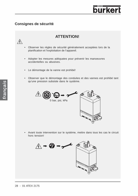
• Avant toute intervention sur le système, mettre dans tous les cas le circuithors tension!
ATTENTION!
0 bar, psi, kPa
Consignes de sécurité
• Observer les règles de sécurité généralement acceptées lors de laplanification et l’exploitation de l’appareil.
• Adopter les mesures adéquates pour prévenir les manoeuvresaccidentelles ou abusives.
• Le démontage de la vanne est prohibé!
• Observer que le démontage des conduites et des vannes est prohibé tantqu’une pression subsiste dans le système.
01 ATEX 2175 - 29
fran
çais
CONDITIONS D'UTILISATION DES BOBINES
1. Montage individuel / montage en batterie
Les bobines d’électro-aimants type AC 21 sont prévues pour le montage individuel etle montage en batterie (voir «Caractéristiques électriques»).
2. Plage de température de service
Observer pour chaque type de bobine la plage de température de service indiquéedans les «Caractéristiques techniques»!
30 - 01 ATEX 2175
fran
çais
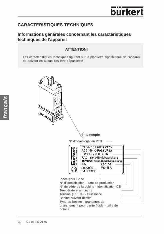
Informations générales concernant les caractéristiquestechniques de l’appareil
ATTENTION!
Les caractéristiques techniques figurant sur la plaquette signalétique de l’appareilne doivent en aucun cas être dépassées!
CARACTERISTIQUES TECHNIQUES
Exemple
N° d'homologation PTB
Place pour CodeN° d'identification - date de productionN° de série de la bobine - Identification CETempérature ambianteTension (±10 %) - PuissanceBobine suivant dessinType de bobine - grandeurs debranchement pour partie fluide - taille debobine
01 ATEX 2175 - 31
fran
çais
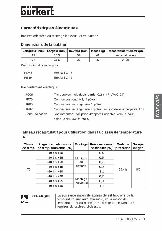
Caractéristiques électriques
Bobines adaptées au montage individuel et en batterie
Dimensions de la bobine
Codification d’homologation:
PD88 EEx ia IIC T6
PE39 EEx ia IIC T5
Raccordement électrique:
JC09 Fils souples individuels sertis, 0,2 mm² (AWG 24)
JF79 Connecteur rond M8, 3 pôles
JF80 Connecteur rectangulaire 2 pôles
JF82 Connecteur rectangulaire 2 pôles, sans collerette de protection
Sans indication Raccordement par prise d’appareil orientée vers le haut,
selon DIN43650 forme C
Tableau récapitulatif pour utilisation dans la classe de températureT6
REMARQUE La puissance maximale admissible est tributaire de latempérature ambiante maximale, de la classe detempérature et du montage. Ces valeurs peuvent êtrereprises du tableau ci-dessus.
Longueur (mm) Largeur (mm) Hauteur (mm) Masse (g) Raccordement électrique27 15,5 34 42 sans indication
27 15,5 28 39 JF80
Classede temp.
Plage max. admissiblede temp. Ambiante [°C]
Montage Puissance max.admissible [W]
Mode deprotection
Groupede gaz
T6
-40 bis +60
Montageen
batterie
0,4
EEx ia IIC
-40 bis +55 0,5
-40 bis +50 0,7
-40 bis +45 0,9
-40 bis +40 1,1
-40 bis +60Montageindividuel
0,7
-40 bis +55 0,9
-40 bis +50 1,1
32 - 01 ATEX 2175
fran
çais
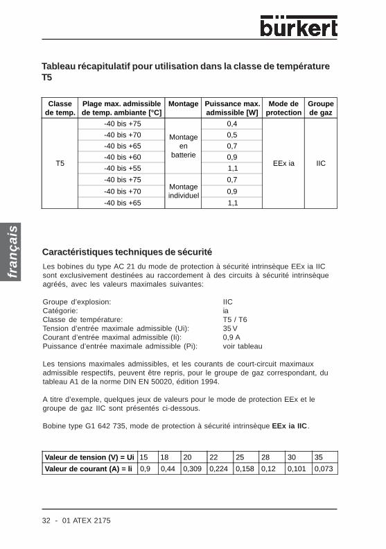
Tableau récapitulatif pour utilisation dans la classe de températureT5
Caractéristiques techniques de sécuritéLes bobines du type AC 21 du mode de protection à sécurité intrinsèque EEx ia IICsont exclusivement destinées au raccordement à des circuits à sécurité intrinsèqueagréés, avec les valeurs maximales suivantes:
Groupe d’explosion: IICCatégorie: iaClasse de température: T5 / T6Tension d’entrée maximale admissible (Ui): 35 VCourant d’entrée maximal admissible (Ii): 0,9 APuissance d’entrée maximale admissible (Pi): voir tableau
Les tensions maximales admissibles, et les courants de court-circuit maximauxadmissible respectifs, peuvent être repris, pour le groupe de gaz correspondant, dutableau A1 de la norme DIN EN 50020, édition 1994.
A titre d’exemple, quelques jeux de valeurs pour le mode de protection EEx et legroupe de gaz IIC sont présentés ci-dessous.
Bobine type G1 642 735, mode de protection à sécurité intrinsèque EEx ia IIC.
Classede temp.
Plage max. admissiblede temp. ambiante [°C]
Montage Puissance max.admissible [W]
Mode deprotection
Groupede gaz
T5
-40 bis +75
Montageen
batterie
0,4
EEx ia IIC
-40 bis +70 0,5
-40 bis +65 0,7
-40 bis +60 0,9
-40 bis +55 1,1
-40 bis +75Montageindividuel
0,7
-40 bis +70 0,9
-40 bis +65 1,1
Valeur de tension (V) = Ui 15 18 20 22 25 28 30 35
Valeur de courant (A) = li 0,9 0,44 0,309 0,224 0,158 0,12 0,101 0,073
01 ATEX 2175 - 33
fran
çais
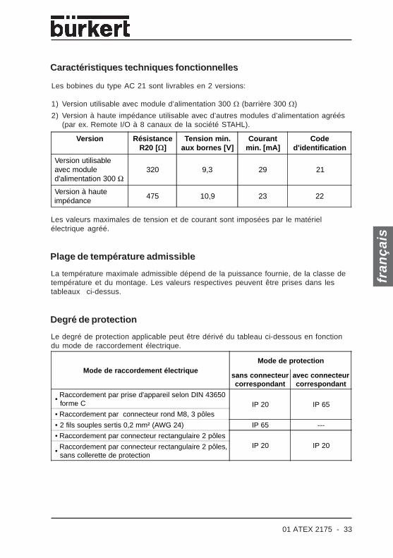
Caractéristiques techniques fonctionnelles
Les bobines du type AC 21 sont livrables en 2 versions:
1) Version utilisable avec module d’alimentation 300 Ω (barrière 300 Ω)
2) Version à haute impédance utilisable avec d’autres modules d’alimentation agréés(par ex. Remote I/O à 8 canaux de la société STAHL).
Les valeurs maximales de tension et de courant sont imposées par le matérielélectrique agréé.
Plage de température admissible
La température maximale admissible dépend de la puissance fournie, de la classe detempérature et du montage. Les valeurs respectives peuvent être prises dans lestableaux ci-dessus.
Le degré de protection applicable peut être dérivé du tableau ci-dessous en fonctiondu mode de raccordement électrique.
Degré de protection
Version RésistanceR20 [Ω]
Tension min.aux bornes [V]
Courantmin. [mA]
Coded'identification
Version utilisableavec moduled'alimentation 300 Ω
320 9,3 29 21
Version à hauteimpédance
475 10,9 23 22
Mode de raccordement électriqueMode de protection
sans connecteurcorrespondant
avec connecteurcorrespondant
•Raccordement par prise d'appareil selon DIN 43650forme C IP 20 IP 65
• Raccordement par connecteur rond M8, 3 pôles
• 2 fils souples sertis 0,2 mm² (AWG 24) IP 65 ---
• Raccordement par connecteur rectangulaire 2 pôlesIP 20 IP 20
•Raccordement par connecteur rectangulaire 2 pôles,sans collerette de protection
34 - 01 ATEX 2175
fran
çais
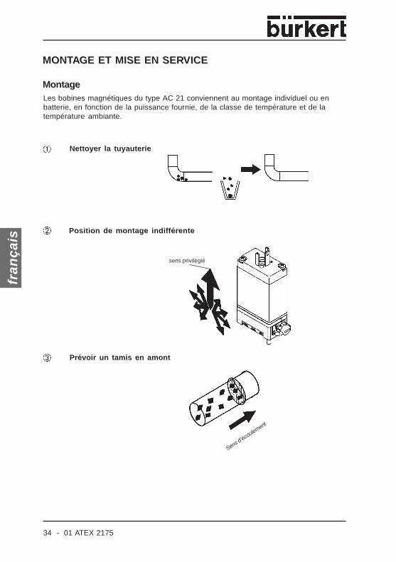
Sens d’écoulement
Nettoyer la tuyauterie
Position de montage indifférente
sens privilégié
Prévoir un tamis en amont
MONTAGE ET MISE EN SERVICE
MontageLes bobines magnétiques du type AC 21 conviennent au montage individuel ou enbatterie, en fonction de la puissance fournie, de la classe de température et de latempérature ambiante.

01 ATEX 2175 - 35
fran
çais
Raccorder les fluides
Montage/démontage
Le démontage de l’appareil est prohibé!
Modes de raccordement
Connecteurrectangulaire avecou sans collerettede protection
2 fils individuels Connecteur rond Prise d’appareilorientée vers lehaut selon DIN43650 forme C
0 bar, psi, kpa
36 - 01 ATEX 2175
fran
çais
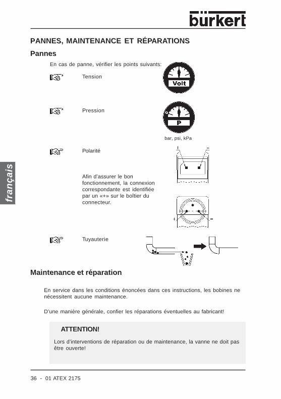
Pannes
Pression
Polarité
Afin d’assurer le bonfonctionnement, la connexioncorrespondante est identifiéepar un «+» sur le boîtier duconnecteur.
bar, psi, kPa
Tuyauterie
En cas de panne, vérifier les points suivants:
Tension
Maintenance et réparation
En service dans les conditions énoncées dans ces instructions, les bobines nenécessitent aucune maintenance.
D’une manière générale, confier les réparations éventuelles au fabricant!
Lors d’interventions de réparation ou de maintenance, la vanne ne doit pasêtre ouverte!
ATTENTION!
PANNES, MAINTENANCE ET RÉPARATIONS

01 ATEX 2175 - 37
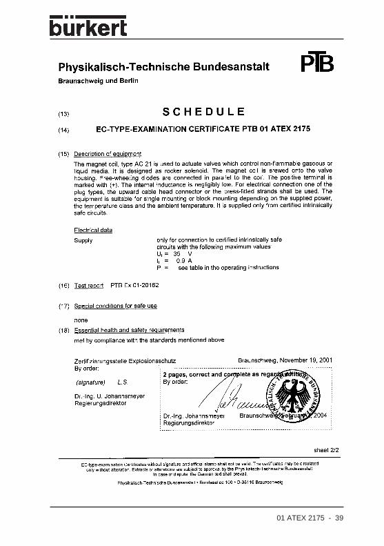
Annex / Anhang / Annexe
PTB 01 ATEX 2175
EC DESIGN TEST CERTIFICATE .................................................................. 38
EG-BAUMUSTERPRÜFBESCHEINIGUNG .................................. 40
CERTIFICAT D’ESSAI DE MODÈLE CE ............................................ 38

38 - 01 ATEX 2175
01 ATEX 2175 - 39

40 - 01 ATEX 2175

01 ATEX 2175 - 41
42 - 01 ATEX 2175


Addresses of BC offices/Adressliste BC Länder Europe/Europa
BC-A Austria, ÖsterreichBürkert-Contromatic G.m.b.H.Diefenbachgasse 1-3A-1150 WienPhone: Int.(+43 1)894 13 33, Nat.(01)894 13 33Fax: Int.(+43 1)894 13 00, Nat.(01)894 13 00E-mail: [email protected]
BC-B Belgium, BelgienBürkert Contromatic NV/SABijkhoevelaan 3B-2110 WijnegemPhone: Int.(+32 3)325 89 00, Nat.(03)325 89 00Fax: Int.(+32 3)325 61 61, Nat.(03)325 61 61E-mail: [email protected]
BC-CZ Czech Rep., Tschech. Rep.Bürkert-Contromatic G.m.b.H. organizacni slozkaKrenova 35CZ-602 00 BrnoPhone: Int.(+420 543)25 25 05,Nat.(543)25 25 05Fax: Int.(+420 543)25 25 06,Nat.(543)25 25 06E-mail: [email protected]
BC-DK Denmark, DänemarkBürkert-Contromatic A/SHørkær 24DK-2730 HerlevPhone: Int.(+45 44)50 75 00, Nat.44-50 75 00Fax: Int.(+45 44)50 75 75, Nat.44-50 75 75E-mail: [email protected]
BC-EST Estonia, EstlandBürkert Oy EestiLaki 11 EEE-12915 TallinPhone: Int.(+3 72)6440 698, Nat.(372)6440 698Fax: Int.(+3 72)6313 759, Nat.(372)6313 759E-mail: [email protected]
BC-SF Finland, FinnlandBürkert OyAtomitie 5FI-00370 HelsinkiPhone: Int.(+358 9)549 706 00,Nat.(09)549 70600Fax: Int.(+358 9)503 12 75,Nat.(09)503 1275E-mail: [email protected]
BC-F France, FrankreichBurkert Contromatic SARLRue du GiessenFR-67220 Triembach au ValPhone: Int.(+33 388)58 91 11,Nat.(0388)58 91 11Fax: Int.(+33 388)57 20 08,Nat.(0388)57 20 08E-mail: [email protected]
BC-I Italy, ItalienBurkert Contromatic Italiana S.p.A.Centro Direzionale „Colombirolo“Via Roma, 74IT-20060 Cassina De’ Pecchi (Mi)Phone: Int.(+39 02)959 071,Nat.(02)959 071Fax: Int.(+39 02)959 07251,Nat.(02)959 07 251E-mail: [email protected]
BC-NL Netherlands, NiederlandeBürkert Contromatic BVComputerweg 9NL-3542 DP UtrechtPhone: Int.(+31 346)58 10 10,Nat.(0346)58 10 10Fax: Int.(+31 346)56 37 17,Nat.(0346)56 37 17E-mail: [email protected]
BC-P Portugal, PortugalPhone: Int.(+35121)21 28 490, Nat.(21)21 28 490Fax: Int.(+35121)21 28 491, Nat.(21)21 28 491E-mail: [email protected]
BC-PL Poland, PolenBurkert-Contromatic GmbHOddzial w PolsceBernardynska street 14 aPL-02-904 WarszawaPhone: Int.(+48 22)840 60 10,Nat.(022)840 60 10Fax: Int.(+48 22)840 60 11,Nat.(022)840 60 11E-mail: [email protected]
BC-E Spain, SpanienBürkert Contromatic S.A.Avda. Barcelona, 40ES-08970 Sant Joan Despi, BarcelonaPhone: Int.(+34 93)477 79 80, Nat.(93)477 79 80Fax: Int.(+34 93)477 79 81, Nat.(93)477 79 81E-mail: [email protected]
BC-S Sweden, SchwedenBürkert-Contromatic ABSkeppsbron 13 BSE-211 20 MalmöPhone: Int.(+46 40)664 51 00,Nat.(040)664 51 00Fax: Int.(+46 40)664 51 01,Nat. (040)664 51 01E-mail: [email protected]
BC-CH Switzerland, SchweizBürkert-Contromatic AG SchweizBösch 71CH-6331 Hünenberg ZGPhone: Int.(+41 41)785 66 66, Nat.(041)785 66 66Fax: Int.(+41 41)785 66 33, Nat.(041)785 66 33E-mail: [email protected]
BC-TR Turkey, TürkeiBurkert Contromatic AkiskanKontrol Sistemleri Ticaret A.S.1203/8 Sok. No2-ETR-Yenisehir, IzmirPhone: Int.(+90 232)459 5395,Nat.(0232)459 5395Fax: Int.(+90 232)459 7694,Nat.(0232)459 7694E-mail: [email protected]
BC-UK United Kingdom,Vereinigtes Königreich
Burkert Contromatic LimitedBrimscombe Port Business ParkBrimscombe, StroudGlos, GL5 2QF /UNITED KINGDOMPhone: Int.(+44 1453)73 13 53,Nat.(01453)73 13 53Fax: Int.(+44 1453)73 13 43,Nat.(01453)73 13 43E-mail: [email protected] Norway, Norwegen
Bürkert-Contromatic A/SHvamstubben 17NO-2013 SkjettenPhone: Int.(+47 63)84 44 10,Nat.(63)84 44 10Fax: Int.(+47 63)84 44 55,Nat.(63)84 44 55E-mail: [email protected]
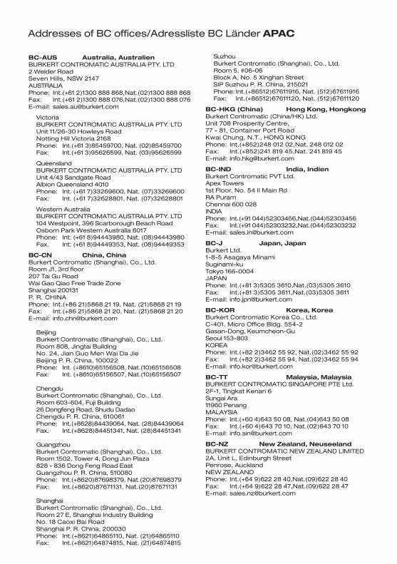
Addresses of BC offices/Adressliste BC Länder APAC
BC-AUS Australia, AustralienBURKERT CONTROMATIC AUSTRALIA PTY. LTD2 Welder RoadSeven Hills, NSW 2147AUSTRALIAPhone: Int.(+61 2)1300 888 868,Nat.(02)1300 888 868Fax: Int.(+61 2)1300 888 076,Nat.(02)1300 888 076E-mail: [email protected]
VictoriaBURKERT CONTROMATIC AUSTRALIA PTY. LTDUnit 11/26-30 Howleys RoadNotting Hill Victoria 2168Phone: Int.(+61 3)85459700, Nat. (02)85459700Fax: Int.(+61 3)95626599, Nat. (03)95626599
QueenslandBURKERT CONTROMATIC AUSTRALIA PTY. LTDUnit 4/43 Sandgate RoadAlbion Queensland 4010Phone: Int. (+61 7)33269600, Nat. (07)33269600Fax: Int. (+61 7)32628801, Nat. (07)32628801
Western AustraliaBURKERT CONTROMATIC AUSTRALIA PTY. LTD104 Westpoint, 396 Scarborough Beach RoadOsborn Park Western Australia 6017Phone: Int: (+61 8)94443980, Nat. (08)94443980Fax. Int: (+61 8)94449353, Nat. (08)94449353
BC-CN China, ChinaBurkert Contromatic (Shanghai), Co., Ltd.Room J1, 3rd floor207 Tai Gu RoadWai Gao Qiao Free Trade ZoneShanghai 200131P. R. CHINAPhone: Int.(+86 21)5868 21 19, Nat. (21)5868 21 19Fax: Int.(+86 21)5868 21 20, Nat. (21)5868 21 20E-mail: [email protected]
BeijingBurkert Contromatic (Shanghai), Co., Ltd.Room 808, Jingtai BuildingNo. 24, Jian Guo Men Wai Da JieBeijing P. R. China, 100022Phone: Int. (+8610)65156508, Nat.(10)65156508Fax: Int. (+8610)65156507, Nat.(10)65156507
ChengduBurkert Contromatic (Shanghai), Co., Ltd.Room 603-604, Fuji Building26 Dongfeng Road, Shudu DadaoChengdu P. R. China, 610061Phone: Int.(+8628)84439064, Nat. (28)84439064Fax. Int.(+8628)84451341, Nat. (28)84451341
GuangzhouBurkert Contromatic (Shanghai), Co., Ltd.Room 1502, Tower 4, Dong Jun Plaza828 - 836 Dong Feng Road EastGuangzhou P. R. China, 510080Phone: Int.(+8620)87698379, Nat.(20)87698379Fax: Int.(+8620)87671131, Nat.(20)87671131
ShanghaiBurkert Contromatic (Shanghai), Co., Ltd.Room 27 E, Shanghai Industry BuildingNo. 18 Caoxi Bai RoadShanghai P. R. China, 200030Phone: Int.(+8621)64865110, Nat. (21)64865110Fax: Int.(+8621)64874815, Nat. (21)64874815
SuzhouBurkert Contromatic (Shanghai), Co., Ltd.Room 5, #06-06Block A, No. 5 Xinghan StreetSIP Suzhou P. R. China, 215021Phone: Int.(+86512)67611916, Nat. (512)67611916Fax: Int.(+86512)67611120, Nat. (512)67611120
BC-HKG (China) Hong Kong, HongkongBurkert Contromatic (China/HK) Ltd.Unit 708 Prosperity Centre,77 - 81, Container Port RoadKwai Chung, N.T., HONG KONGPhone: Int.(+852)248 012 02,Nat. 248 012 02Fax: Int.(+852)241 819 45,Nat. 241 819 45E-mail: [email protected]
BC-IND India, IndienBurkert Contromatic PVT Ltd.Apex Towers1st Floor, No. 54 II Main RdRA PuramChennai 600 028INDIAPhone: Int.(+91 044)52303456,Nat.(044)52303456Fax: Int.(+91 044)52303232,Nat.(044)52303232E-mail: [email protected]
BC-J Japan, JapanBurkert Ltd.1-8-5 Asagaya MinamiSuginami-kuTokyo 166-0004JAPANPhone: Int.(+81 3)5305 3610,Nat.(03)5305 3610Fax: Int.(+81 3)5305 3611,Nat.(03)5305 3611E-mail: [email protected]
BC-KOR Korea, KoreaBurkert Contromatic Korea Co., Ltd.C-401, Micro Office Bldg. 554-2Gasan-Dong, Keumcheon-GuSeoul 153-803KOREAPhone: Int.(+82 2)3462 55 92, Nat.(02)3462 55 92Fax: Int.(+82 2)3462 55 94, Nat.(02)3462 55 94E-mail: [email protected]
BC-TT Malaysia, MalaysiaBURKERT CONTROMATIC SINGAPORE PTE Ltd.2F-1, Tingkat Kenari 6Sungai Ara11960 PenangMALAYSIAPhone: Int.(+60 4)643 50 08, Nat.(04)643 50 08Fax: Int.(+60 4)643 70 10, Nat.(02)643 70 10E-mail: [email protected]
BC-NZ New Zealand, NeuseelandBURKERT CONTROMATIC NEW ZEALAND LIMITED2A, Unit L, Edinburgh StreetPenrose, AucklandNEW ZEALANDPhone: Int.(+64 9)622 28 40,Nat.(09)622 28 40Fax: Int.(+64 9)622 28 47,Nat.(09)622 28 47E-mail: [email protected]
Addresses of BC offices/Adressliste BC Länder NAFTA
BC-BRA Brazil, BrasilienBürkert-Contromatic Brasil Ltda.Rua Américo Brasiliense, 2171 cj.100704715-005 São Paulo - SPBRAZILPhone: Int.(+55 11)5182 0011, Nat.(011)5182 0011Fax: Int.(+55 11)5182 8899, Nat.(011)5182 8899E-mail: [email protected]
BC-CDN Canada, KanadaBürkert Contromatic Inc.760 Pacific Road, Unit 3Oakville, Ontario L6L 6M5CANADAPhone: Int.(+1 905)847 55 66,Nat.(905)847 55 66Fax: Int.(+1 905)847 90 06,Nat.(905)847 90 06E-mail: [email protected]
BC-SA South Africa, SüdafrikaBürkert Contromatic Pty. Ltd.P.O. Box 26260East Rand1462SOUTH AFRICAPhone: Int.(+27 11)574 60 00, Nat.(011)574 60 00Fax: Int.(+27 11)454 14 77, Nat.(011)454 14 77E-mail: [email protected]
Addresses of BC offices/Adressliste BC Länder AFRICA/AFRIKA
Addresses of BC offices/Adressliste BC Länder APAC
BC-RP Philippines, PhilippinenBURKERT CONTROMATIC PHILIPPINES, INC.8467, West Service Road Km 14South Superhighway, SunvalleyParanaque City, Metro ManilaPHILIPPINESPhone: Int.(+63 2)776 43 84, Nat.(02)776 43 84Fax: Int.(+63 2)776 43 82, Nat.(02)776 43 82E-mail: [email protected]
BC-SIN Singapore, SingapurBURKERT CONTROMATIC SINGAPORE PTE. LTD.51 Ubi Avenue 1, #03-14Paya Ubi Industrial ParkSingapore 408933SINGAPOREPhone: Int.(+65)6844 2233,Nat.6844 2233Fax: Int.(+65)6844 3532,Nat.6844 3532E-mail: [email protected]
BC-RC Taiwan, TaiwanBurkert Contromatic Taiwan Ltd.9 F, No. 32, Chenggong Road, Sec. 1,Nangang DistrictTaipeiTAIWAN 115, R.O.C.Phone: Int.(+886 2)2653 78 68,Nat.(02)2653 78 68Fax: Int.(+886 2)2653 79 68,Nat.(02)2653 79 68E-mail: [email protected]
BC-USA USA, USABURKERT CONTROMATIC CORP.2602 McGaw AvenueIrvine, CA 92614USAPhone: Int.(+1 949)223 31 00,Nat.(949)223 31 00Fax: Int.(+1949)223 31 98,Nat.(949)223 31 98E-mail: [email protected]

Adressliste Bürkert Fluid Control Systems Deutschland
Headquarter and Service Center,Stammsitz und Service-Center
IngelfingenBürkert GmbH & Co. KGChristian-Bürkert-Straße 13 - 17DE-74653 IngelfingenTelefon: Int. (+497940)10-111, Nat. (07940)10-111Fax: Int. (+497940)10-448, Nat. (07940)10-448E-mail: [email protected]
Distribution Center, Vertriebs-Center
BerlinBürkert GmbH & Co. KGParadiesstraße 206 bDE-12526 BerlinTelefon: Int. (+4930)6797170, Nat. (030)6797170Fax: Int. (+4930)67971766, Nat. (030)67971766
HannoverBürkert GmbH & Co. KGRendsburger Straße 12DE-30659 HannoverTelefon:Int. (+49511)902760, Nat. (0511)902760Fax: Int. (+49511)9027666, Nat. (0511)9027666
DortmundBürkert GmbH & Co. KGHolzener Straße 70DE-58708 MendenTelefon:Int. (+492373)96810, Nat. (02373)96810Fax: Int. (+492373)968150, Nat. (02373)968150
FrankfurtBürkert GmbH & Co. KGAm Flugplatz 27DE-63329 EgelsbachTelefon: Int. (+496103)94140, Nat. (06103)94140Fax: Int. (+496103)941466, Nat. (06103)941466
StuttgartBürkert GmbH & Co. KGKarl-Benz-Straße 19DE-70794 Filderstadt-BernhausenTelefon: Int. (+49711)451100, Nat. (0711)451100Fax: Int. (+49711)4511066, Nat. (0711)4511066
MünchenBürkert GmbH & Co. KGPaul-Gerhardt-Allee 24DE-81245 MünchenTelefon: Int. (+4989)8292280, Nat. (089)8292280Fax: Int. (+4989)82922850, Nat. (089)82922850
Service-Center, Dienstleistungs-Center
DortmundBürkert GmbH & Co. KGHolzener Straße 70DE-58708 MendenTelefon: Int. (+492373)968134, Nat. (02373)968134Fax: Int. (+492373)968132, Nat. (02373)968132
DresdenBürkert GmbH & Co. KGChristian-Bürkert-Straße 2DE-01900 GroßröhrsdorfTelefon: Int. (+4935952)36-300, Nat. (035952)36-300Fax: Int. (+4935952)36-551, Nat. (035952)36-551


The smart choiceof Fluid Control Systems
www.buerkert.com