montage- und betriebsanleitung mounting and operating ... · manual de instruções e de montagem...
TRANSCRIPT

OI_BNA_EX_pt_en.doc Rev. 7 – 16.03.2015
Manual de Instruções e de Montagem
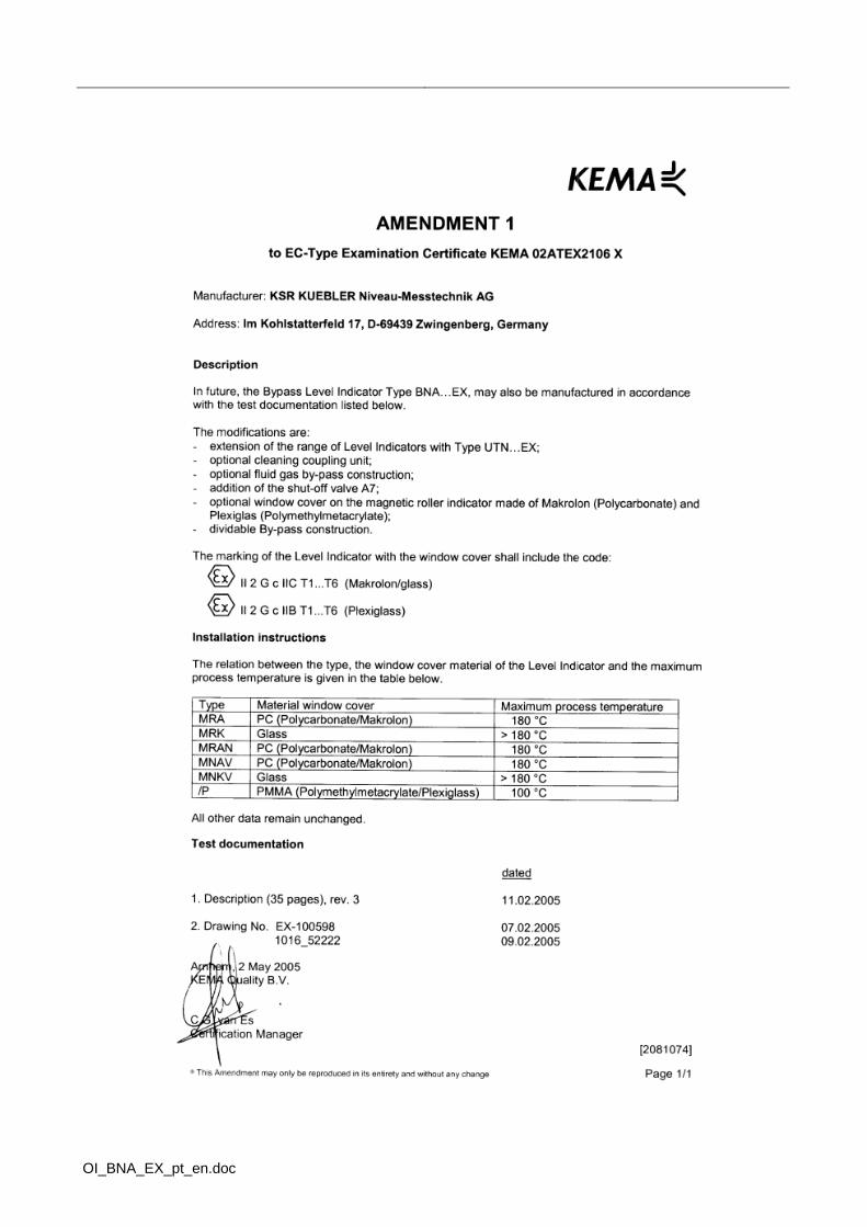
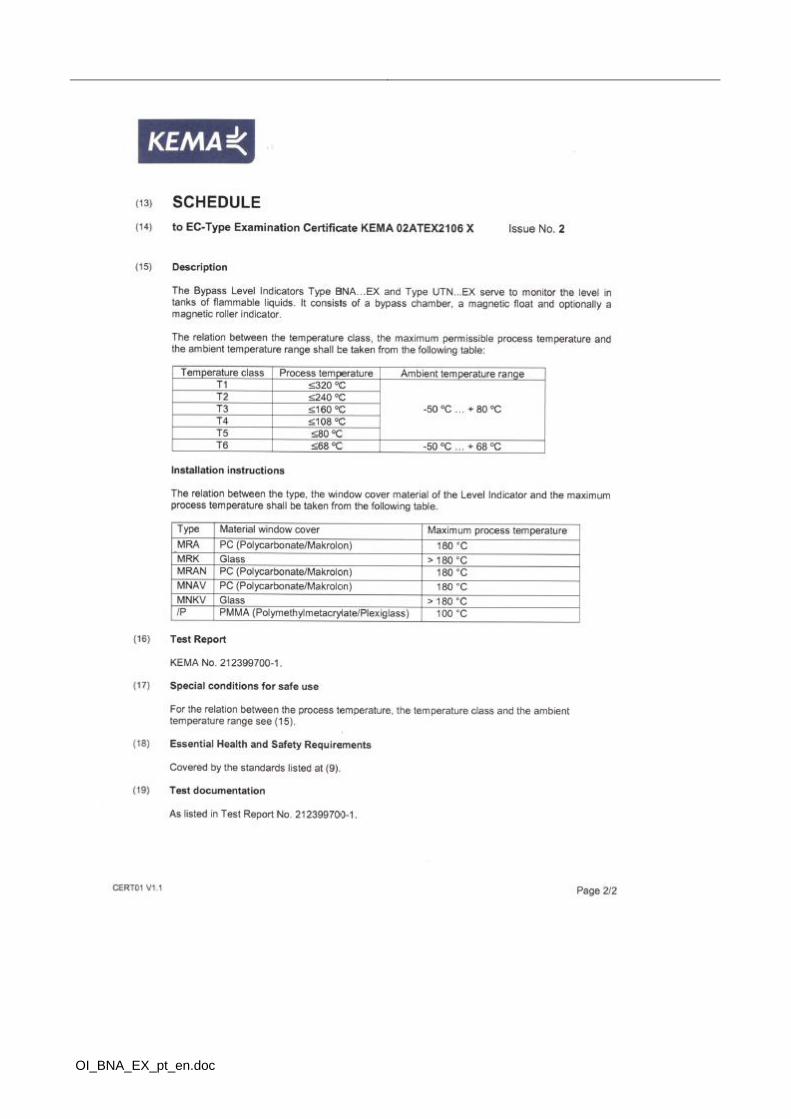
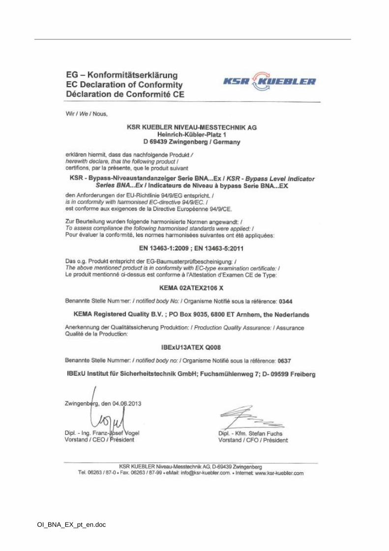
KEMA 02ATEX2106 X
Por favor, guarde esta informação para uso futuro Please retain for future usage
BNA...EX
Montage- und Betriebsanleitung
Mounting and operating instruction


OI_BNA_EX_pt_en.doc
OI_BNA_EX_pt_en.doc

OI_BNA_EX_pt_en.doc
OI_BNA_EX_pt_en.doc
OI_BNA_EX_pt_en.doc

OI_BNA_EX_pt_en.doc
Português .......................................................................................................................................................... 1 Legenda de Símbolos ........................................................................................................................................ 1 Instruções de Segurança ................................................................................................................................... 1
Perigo! ............................................................................................................................................................ 2 Utilização e área de aplicação ........................................................................................................................... 2 Atenção! ............................................................................................................................................................. 2
Remover a embalagem de transporte e o material de segurança ................................................................ 2 Instalação de comissionamento do BNA...EX em área de risco ....................................................................... 3
Instalação do flutuador ................................................................................................................................... 3 Instalação de comissionamento do BNA...EX aquecido em um projeto de parede dupla em área de risco .... 4
Montagem de dispositivos de avaliação para o BNA...EX em área de risco ................................................. 5 Exemplo de montagem (transdutores MG... ) ................................................................................................ 5
Número recomendado de talas ou cintos de aperto .................................................................................. 5 Exemplo de montagem MRA (montagem de interruptor magnético em rolos magnéticos – indicador de nível) .............................................................................................................................................................. 6 Exemplo de montagem MNAV (montagem do interruptor magnético em barra de retenção) ...................... 6 Manutenção ................................................................................................................................................... 7
Informação! ........................................................................................................................................................ 7 Solução de problemas ................................................................................................................................... 7
Typcode BNA...EX ............................................................................................................................................. 8 Typcode Bypass - Niveaustandanzeiger ....................................................................................................... 8 Código tipo KSR-cilindro flutuador ............................................................................................................... 10
Execução sem grânulos ........................................................................................................................... 10 Tipo de proteção contra ignição ...................................................................................................................... 11 Dados de temperatura ..................................................................................................................................... 11 Dados de pressão ............................................................................................................................................ 11 English ............................................................................................................................................................. 12 Symbol legend ................................................................................................................................................. 12 Safety information ............................................................................................................................................ 12
Danger! ........................................................................................................................................................ 13 Application and field of use .............................................................................................................................. 13 Attention ! ......................................................................................................................................................... 13
Removal of transport packaging and transport safety devices .................................................................... 13 Installation and putting into operation of the BNA…EX bypass level indicator in explosion risk areas .......... 14
Installation of float ........................................................................................................................................ 14 Installation and putting into operation of the BNA…EX bypass level indicator, heated, double-walled version, in explosion risk areas ..................................................................................................................................... 15
Installation of signal processing and display devices on the BNA…EX bypass level indicator in explosion risk areas ...................................................................................................................................................... 16 Example of mounting ( Level Sensor MG... ) ............................................................................................... 16
Number of recommended mounting brackets or tightening straps .......................................................... 16 Example of installation-mounting the magnetic switch on the magnetic roller display ................................ 17 Example of installation MNAV (mounting of magnetic switch on a retainer rod) ......................................... 17 Maintenance ................................................................................................................................................. 18
Important! ......................................................................................................................................................... 18 Error Search ................................................................................................................................................. 18
Type Code BNA...EX ....................................................................................................................................... 19 Type Code KSR Magnetic Level Indicators / Gauges ................................................................................. 19 Type Code KSR Bypass Floats ................................................................................................................... 20
Design with beads .................................................................................................................................... 20 Design without beads ............................................................................................................................... 20
Ignition protection ............................................................................................................................................ 21 Temperatures .................................................................................................................................................. 21 Pressure .......................................................................................................................................................... 21 KSR KUEBLER AG Adressen ......................................................................................................................... 22
1 / 21 OI_BNA_EX_pt_en.doc
Português
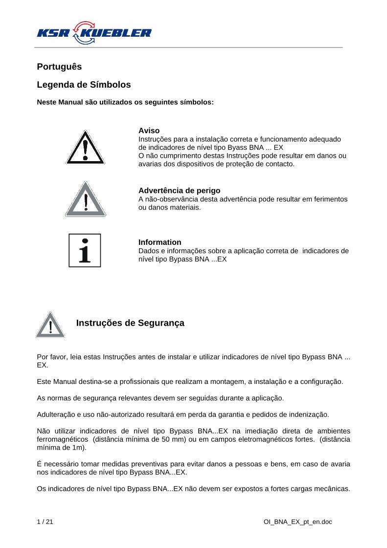
Legenda de Símbolos Neste Manual são utilizados os seguintes símbolos:
Aviso Instruções para a instalação correta e funcionamento adequado de indicadores de nível tipo Byass BNA ... EX
O não cumprimento destas Instruções pode resultar em danos ou avarias dos dispositivos de proteção de contacto.
Advertência de perigo A não-observância desta advertência pode resultar em ferimentos ou danos materiais.
Information Dados e informações sobre a aplicação correta de indicadores de nível tipo Bypass BNA ...EX
Instruções de Segurança
Por favor, leia estas Instruções antes de instalar e utilizar indicadores de nível tipo Bypass BNA ... EX. Este Manual destina-se a profissionais que realizam a montagem, a instalação e a configuração. As normas de segurança relevantes devem ser seguidas durante a aplicação. Adulteração e uso não-autorizado resultará em perda da garantia e pedidos de indenização. Não utilizar indicadores de nível tipo Bypass BNA...EX na imediação direta de ambientes ferromagnéticos (distância mínima de 50 mm) ou em campos eletromagnéticos fortes. (distância mínima de 1m). É necessário tomar medidas preventivas para evitar danos a pessoas e bens, em caso de avaria nos indicadores de nível tipo Bypass BNA...EX. Os indicadores de nível tipo Bypass BNA...EX não devem ser expostos a fortes cargas mecânicas.
OI_BNA_EX_pt_en.doc 2 / 21
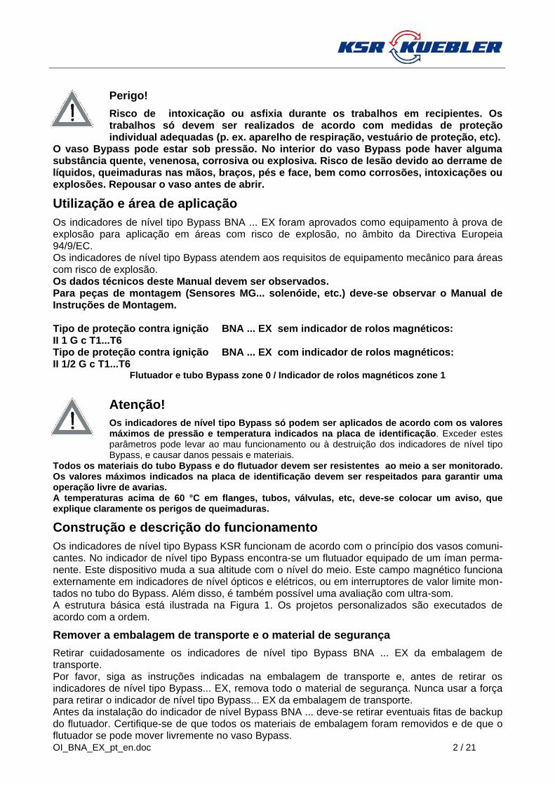
Perigo!
Risco de intoxicação ou asfixia durante os trabalhos em recipientes. Os trabalhos só devem ser realizados de acordo com medidas de proteção individual adequadas (p. ex. aparelho de respiração, vestuário de proteção, etc).
O vaso Bypass pode estar sob pressão. No interior do vaso Bypass pode haver alguma substância quente, venenosa, corrosiva ou explosiva. Risco de lesão devido ao derrame de líquidos, queimaduras nas mãos, braços, pés e face, bem como corrosões, intoxicações ou explosões. Repousar o vaso antes de abrir.
Utilização e área de aplicação
Os indicadores de nível tipo Bypass BNA ... EX foram aprovados como equipamento à prova de explosão para aplicação em áreas com risco de explosão, no âmbito da Directiva Europeia 94/9/EC. Os indicadores de nível tipo Bypass atendem aos requisitos de equipamento mecânico para áreas com risco de explosão. Os dados técnicos deste Manual devem ser observados. Para peças de montagem (Sensores MG... solenóide, etc.) deve-se observar o Manual de Instruções de Montagem. Tipo de proteção contra ignição BNA ... EX sem indicador de rolos magnéticos: II 1 G c T1...T6 Tipo de proteção contra ignição BNA ... EX com indicador de rolos magnéticos: II 1/2 G c T1...T6 Flutuador e tubo Bypass zone 0 / Indicador de rolos magnéticos zone 1
Atenção!
Os indicadores de nível tipo Bypass só podem ser aplicados de acordo com os valores máximos de pressão e temperatura indicados na placa de identificação. Exceder estes parâmetros pode levar ao mau funcionamento ou à destruição dos indicadores de nível tipo Bypass, e causar danos pessais e materiais.
Todos os materiais do tubo Bypass e do flutuador devem ser resistentes ao meio a ser monitorado. Os valores máximos indicados na placa de identificação devem ser respeitados para garantir uma operação livre de avarias. A temperaturas acima de 60 °C em flanges, tubos, válvulas, etc, deve-se colocar um aviso, que explique claramente os perigos de queimaduras.
Construção e descrição do funcionamento
Os indicadores de nível tipo Bypass KSR funcionam de acordo com o princípio dos vasos comuni-cantes. No indicador de nível tipo Bypass encontra-se um flutuador equipado de um íman perma-nente. Este dispositivo muda a sua altitude com o nível do meio. Este campo magnético funciona externamente em indicadores de nível ópticos e elétricos, ou em interruptores de valor limite mon-tados no tubo do Bypass. Além disso, é também possível uma avaliação com ultra-som. A estrutura básica está ilustrada na Figura 1. Os projetos personalizados são executados de acordo com a ordem.
Remover a embalagem de transporte e o material de segurança
Retirar cuidadosamente os indicadores de nível tipo Bypass BNA ... EX da embalagem de transporte. Por favor, siga as instruções indicadas na embalagem de transporte e, antes de retirar os indicadores de nível tipo Bypass... EX, remova todo o material de segurança. Nunca usar a força para retirar o indicador de nível tipo Bypass... EX da embalagem de transporte. Antes da instalação do indicador de nível Bypass BNA ... deve-se retirar eventuais fitas de backup do flutuador. Certifique-se de que todos os materiais de embalagem foram removidos e de que o flutuador se pode mover livremente no vaso Bypass.

3 / 21 OI_BNA_EX_pt_en.doc
Instalação de comissionamento do BNA...EX em área de risco
O indicador de nível tipo Bypass BNA...EX é instalado em posição vertical no recipiente a ser monitorado, mediante os processos de conexão previstos (1). Para o processo de conexão na montagem deve-se utilizar juntas (2), parafusos (3), arruelas
(4) e porcas (5). Quanto ao tipo de selagem, verificar a resistência adequada à corrosão. Se necessário, instalar válvulas de fechamento entre o tanque e o Bypass. Em termos de proteção contra explosão, os respetivos valores máximos de BNA... Ex devem ser observados em conexão com as leis e regulamentos aplicáveis (prova de segurança intrínseca). Particularmente importante é a observância de eventuais "condições
especiais" inerentes à mesma. Por favor, consulte os valores de torque dos parafusos.
Deve-se aplicar selagens apropriadas. Verificar se o material de selagem contra o meio e os seus vapores, a temperatura e cargas de pressão previstas são resistentes.
Instalação do flutuador
1. Remover a flange inferior (7) e introduzir o flutuador (6) no tubo a partir da parte inferior. (verificar a marcação "top".)
2. Colocar a selagem (9) na flange inferior. Colocar de novo a flange inferior, e fixar com parafusos (8).
Atenção!
As extremidades inferior e su-perior do tubo (p.ex. flange) têm uma proteção contra quedas
constituída por uma mola aplicada com disco PTFE. Isto serve para o amortecimento em caso de impacto do flutuador, impedindo o choque de metais. Durante a montagem e desmontagem do flutuador deve-se prevenir qualquer dano na protecção contra quedas.
6
9
1
3
7
245
8
M
L1
L2
L = Unterer Überstand ist abhängig von der Dichte des Mediums
Fig. 1
L = O flutuador inferior depende da densidade do meio
OI_BNA_EX_pt_en.doc 4 / 21
Instalação de comissionamento do BNA...EX aquecido em um projeto de parede dupla em área de risco
O tubo Bypass deve ser também relacionado em uma exelcução aquecida de parede dupla Aqui, o tubo de Bypass está rodeado por um segundo tubo. A câmara de parede dupla assim formada pode fluir através de duas conexões com fluido ou vapor aquecido (transferência de calor). A concepção de materiais para temperaturas mais elevadas ocorre em graus inoxidável, segundo os folhetos AD.
Para eliminar o risco de explosão devido ao aquecimento, aplicam-se os seguintes requisitos para a operação de aquecimento e para a transferência de calor:
1. A temperatura de transferência de calor não deve exceder 80% da temperatura de ignição dos produtos armazenados.
2. Através de monitoramento constante e controle do funcionamento por parte do operador deve assegurar-se que a temperatura de ignição referida no ponto 1 não seja excedida. Aqui, as temperaturas por reação química devem ser também observadas. A observância da temperatura permitida pode, por exemplo, ser assegurada pela pressão de vapor saturado ou pelo ponto de ebulição de um líquido.
5 / 21 OI_BNA_EX_pt_en.doc
1
2
3
4 5
6 7
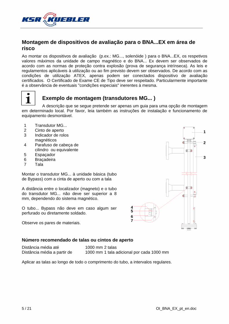
Montagem de dispositivos de avaliação para o BNA...EX em área de risco
Ao montar os dispositivos de avaliação (p.ex.: MG..., solenóide ) para o BNA...EX, os respetivos valores máximos da unidade de campo magnético e do BNA... Ex devem ser observados de acordo com as normas de proteção contra explosão (prova de segurança intrínseca). As leis e regulamentos aplicáveis à utilização ou ao fim previsto devem ser observados. De acordo com as condições de utilização ATEX, apenas podem ser conectados dispositivo de avaliação certificados. O Certificado de Exame CE de Tipo deve ser respeitado. Particularmente importante é a observância de eventuais "condições especiais" inerentes à mesma.
Exemplo de montagem (transdutores MG... )
A descrição que se segue pretende ser apenas um guia para uma opção de montagem em determinado local. Por favor, leia também as instruções de instalação e funcionamento de equipamento desmontável.
Montar o transdutor MG... à unidade básica (tubo de Bypass) com a cinta de aperto ou com a tala A distância entre o localizador (magneto) e o tubo do transdutor MG... não deve ser superior a 8 mm, dependendo do sistema magnético. O tubo... Bypass não deve em caso algum ser perfurado ou diretamente soldado. Observe os pares de materiais.
Número recomendado de talas ou cintos de aperto
Distância média até 1000 mm 2 talas Distância média a partir de 1000 mm 1 tala adicional por cada 1000 mm Aplicar as talas ao longo de todo o comprimento do tubo, a intervalos regulares.
1 Transdutor MG... 2 Cinto de aperto 3 Indicador de rolos
magnéticos 4 Parafuso de cabeça de
cilindro ou equivalente 5 Espaçador 6 Braçadeira 7 Tala
OI_BNA_EX_pt_en.doc 6 / 21
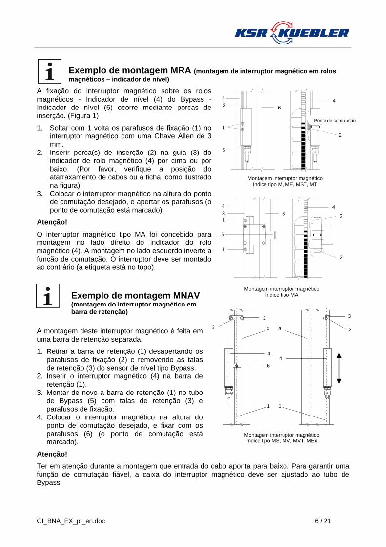
Exemplo de montagem MRA (montagem de interruptor magnético em rolos
magnéticos – indicador de nível)
A fixação do interruptor magnético sobre os rolos magnéticos - Indicador de nível (4) do Bypass - Indicador de nível (6) ocorre mediante porcas de inserção. (Figura 1)
1. Soltar com 1 volta os parafusos de fixação (1) no interruptor magnético com uma Chave Allen de 3 mm.
2. Inserir porca(s) de inserção (2) na guia (3) do indicador de rolo magnético (4) por cima ou por baixo. (Por favor, verifique a posição do atarraxamento de cabos ou a ficha, como ilustrado na figura)
3. Colocar o interruptor magnético na altura do ponto de comutação desejado, e apertar os parafusos (o ponto de comutação está marcado).
Atenção!
O interruptor magnético tipo MA foi concebido para montagem no lado direito do indicador do rolo magnético (4). A montagem no lado esquerdo inverte a função de comutação. O interruptor deve ser montado ao contrário (a etiqueta está no topo).
Exemplo de montagem MNAV (montagem do interruptor magnético em barra de retenção)
A montagem deste interruptor magnético é feita em uma barra de retenção separada.
1. Retirar a barra de retenção (1) desapertando os parafusos de fixação (2) e removendo as talas de retenção (3) do sensor de nível tipo Bypass.
2. Inserir o interruptor magnético (4) na barra de retenção (1).
3. Montar de novo a barra de retenção (1) no tubo de Bypass (5) com talas de retenção (3) e parafusos de fixação.
4. Colocar o interruptor magnético na altura do ponto de comutação desejado, e fixar com os parafusos (6) (o ponto de comutação está marcado).
Atenção!
Ter em atenção durante a montagem que entrada do cabo aponta para baixo. Para garantir uma função de comutação fiável, a caixa do interruptor magnético deve ser ajustado ao tubo de Bypass.
1
4
3
5
Schaltpunkt
2
Montage Magnetschalter
Typindex M, ME, MST, MT
4
6
3
4
1
1
2
2
Montage Magnetschalter
Typindex MA
5
6
4
5 5
1 1
3
2
2
3
4
6
4
Montage Magnetschalter
Typindex MS, MV, MVT, MEx
Ponto de comutação
Montagem interruptor magnético Índice tipo M, ME, MST, MT
Montagem interruptor magnético Índice tipo MA
Montagem interruptor magnético Índice tipo MS, MV, MVT, MEx

7 / 21 OI_BNA_EX_pt_en.doc
Manutenção
os indicares de nível tipo Bypass BNA...EX funcionam normalmente sem manutenção. No entanto, no âmbito da revisão regular, estão sujeitos a inspeção visual, incluindo o teste de pressão do recipiente.
Informação!
O flutuador foi projetado para a densidade do meio indicada no rótulo. Na aplicação em líquidos com densidade específica diferente, surgem desvios na medição.
O meio a ser monitorado não deve apresentar qualquer contaminação grave ou partes ásperas. Não deve tender a cristalizar O indicador de rolos magnéticos e o interruptor magnético anexo devem ser alinhados mediante o flutuador antes da montagem. O indicador de nível tipo Bypass não deve ser instalado nas imediações de campos magnéticos fortes. (distância mínima de 1m). A função apropriada dos indicadores de nível tipo Bypass só pode ser garantida com a utilização de acessórios originais KSR Kuebler e peças de reposição.
Solução de problemas
Na tabela a seguir estão listados os problemas mais comuns e as contramedidas necessárias
Erro Causa Medida
O indicador de nível não pode ser anexado ao recipiente, no espaço previsto
Incompatibilidade do tamanho da rosca ou do flange do indicador de nível Bypass
Reconstrução do recipiente
Reenviar para a fábrica
A rosca de encaixe das buchas de fixação no recipiente está defeituosa
Trabalhos de reparação da rosca de encaixe ou troca das buchas de fixação
O parafuso de rosca no indicador de nível Bypass está defeituoso
Reenviar para a fábrica
A distância central do recipiente não corresponde à distância central do indicador de nível Bypass
Reconstrução do recipiente
Reenviar para a fábrica
As ligações de processo não estão paralelas entre si.
Reconstrução do recipiente
Em caso de dificuldades, entre em contacto conosco. Estaremos sempre à sua disposição com palavras e ações.
OI_BNA_EX_pt_en.doc 8 / 21
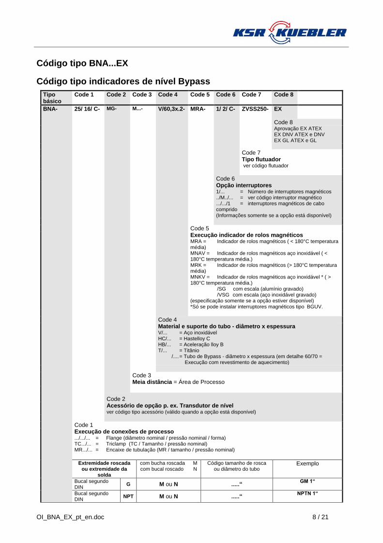
Código tipo BNA...EX
Código tipo indicadores de nível Bypass
Tipo básico
Code 1 Code 2 Code 3 Code 4 Code 5 Code 6 Code 7 Code 8
BNA- 25/ 16/ C- MG- M...- V/60,3x.2- MRA- 1/ 2/ C- ZVSS250- EX
Code 8 Aprovação EX ATEX EX DNV ATEX e DNV EX GL ATEX e GL
Code 7 Tipo flutuador ver código flutuador
Code 6 Opção interruptores 1/... = Número de interruptores magnéticos ../M../... = ver código interruptor magnético .../.../1 = interruptores magnéticos de cabo comprido (Informações somente se a opção está disponível)
Code 5 Execução indicador de rolos magnéticos MRA = Indicador de rolos magnéticos ( < 180°C temperatura média) MNAV = Indicador de rolos magnéticos aço inoxidável ( < 180°C temperatura média.) MRK = Indicador de rolos magnéticos (> 180°C temperatura média) MNKV = Indicador de rolos magnéticos aço inoxidável * ( > 180°C temperatura média.) /SG com escala (alumínio gravado) /VSG com escala (aço inoxidável gravado) (especificação somente se a opção estiver disponível) *Só se pode instalar interruptores magnéticos tipo BGUV.
Code 4 Material e suporte do tubo - diâmetro x espessura V/... = Aço inoxidável HC/... = Hastelloy C HB/... = Aceleração lloy B T/... = Titânio /.... = Tubo de Bypass - diâmetro x espessura (em detalhe 60/70 = Execução com revestimento de aquecimento)
Code 3 Meia distância = Área de Processo
Code 2 Acessório de opção p. ex. Transdutor de nível ver código tipo acessório (válido quando a opção está disponível)
Code 1 Execução de conexões de processo .../.../... = Flange (diâmetro nominal / pressão nominal / forma) TC.../... = Triclamp (TC / Tamanho / pressão nominal) MR.../... = Encaixe de tubulação (MR / tamanho / pressão nominal)
Extremidade roscada ou extremidade da
solda
com bucha roscada M com bucal roscado N
Código tamanho de rosca ou diâmetro do tubo
Exemplo
Bucal segundo DIN
G M ou N .....“ GM 1“
Bucal segundo DIN
NPT M ou N .....“ NPTN 1“

9 / 21 OI_BNA_EX_pt_en.doc
extremidade da solda
S -- .....“ S 3/4" “
Tipo básico BNA

OI_BNA_EX_pt_en.doc 10 / 21
Código tipo KSR-cilindro flutuador
Execução com grânulos
Tipo básico
Code 1 Code 2 Code 3
Z V SS 250
Code 3 Comprimento do flutuador em mm
Code 2: Flutuador grânulos
Code 1:
Materiais flutuador V Materiais flutuador aço inoxidável máx. 20 bar T Materiais flutuador titânio máx. 16 bar
Tipo básico: Flutuador cilindro
Execução sem grânulos
Tipo básico
Code 1 Code 2 Code 3 Code 4 Code 5 Code 6 Code 7
Z V S 250/ 16/ 60/ 1000 ...
Code 7 Sistema magnético
Code 6 Densidade em kg/m³
Code 5 Temperatura em °C
Code 4 Pressão operacional em bar
Code 3
Comprimento do flutuador em mm
Code 2: Flutuador cilindro liso
Code 1: Materiais flutuador V Materiais flutuador aço inoxidável T Materiais flutuador titânio HC Materiais flutuador aceleração lloy HC HB Materiais flutuador aceleração lloy HB
Tipo básico: Flutuador cilindro

11 / 21 OI_BNA_EX_pt_en.doc
Tipo de proteção contra ignição
Tipo de proteção contra ignição BNA... EX sem indicador de rolos magnéticos: II 1 G c T1...T6
Tipo de proteção contra ignição BNA... EX com indicador de rolos magnéticos: II 1/2 G c T1...T6 Flutuador e tubo Bypass zone 0 / Indicador de rolos magnéticos zone 1
Dados de temperatura
Os valores máximos para a pressão nominal e temperatura indicados na placa de identificação não devem ser excedidos.
Classe -temperatura
Processo máximo de temperatura
BNA...EX
Processo máximo de temperatura -
Temperatura ambiente-máxima
Temperatura ambiente máxima no dispositivo de
avaliação MRA
MRAN
MNAV
MRK
MNKV
T1 320°C ≤ 320°C
- 50... + 80°C
A temperatura ambiente máxima do dispositivo de avaliação deve ser respeitada. A mesma não deve ser excedida em qualquer circunstância. Ver MB descrição dos dispositivos de avaliação
T2 240°C ≤ 180°C ≤ 240°C
T3 160°C ≤ 160°C ≤ 160°C
T4 108°C ≤ 108°C ≤ 108°C
T5 80°C ≤ 80°C ≤ 80°C
T6 68°C ≤ 68°C ≤ 68°C - 50... + 68°C
Dados de pressão
Pressão de teste de acordo com os regulamentos AD 2000
Pressão máxima de funcionamento
Temperatura mínima - máxima
Só se o Bypass for realizado de acordo com a norma DGRL 97/23/EG (pressão de operação acima de 0,5 bar)
Tag No. :
PS. : PT. :
S. G. :
Chamber Mat. :
Float :
Serial No. :
BNA-
-EX
KEMA 02ATEX2106 X II 1 G c T1...T6 or II 1/2 G c T1...T6
____
0637
TS. :
OI_BNA_EX_pt_en.doc 12 / 21
English
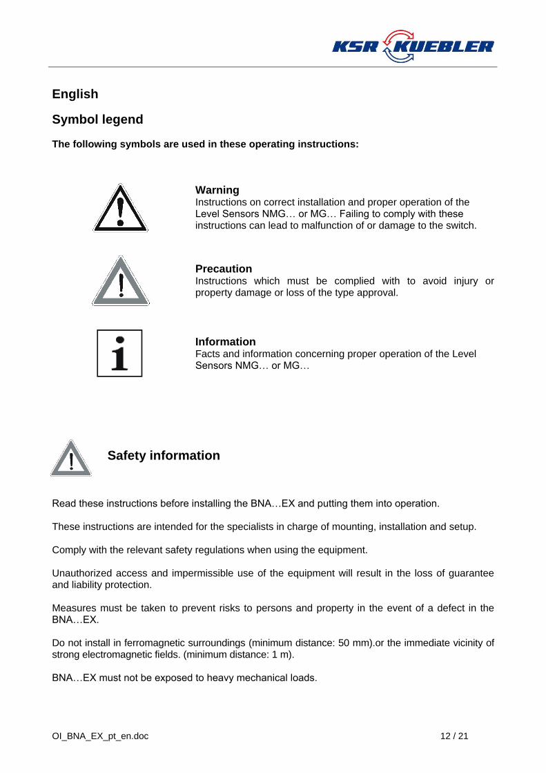
Symbol legend The following symbols are used in these operating instructions:
Warning Instructions on correct installation and proper operation of the Level Sensors NMG… or MG… Failing to comply with these instructions can lead to malfunction of or damage to the switch.
Precaution Instructions which must be complied with to avoid injury or property damage or loss of the type approval.
Information Facts and information concerning proper operation of the Level Sensors NMG… or MG…
Safety information
Read these instructions before installing the BNA…EX and putting them into operation. These instructions are intended for the specialists in charge of mounting, installation and setup. Comply with the relevant safety regulations when using the equipment. Unauthorized access and impermissible use of the equipment will result in the loss of guarantee and liability protection. Measures must be taken to prevent risks to persons and property in the event of a defect in the BNA…EX. Do not install in ferromagnetic surroundings (minimum distance: 50 mm).or the immediate vicinity of strong electromagnetic fields. (minimum distance: 1 m). BNA…EX must not be exposed to heavy mechanical loads.
13 / 21 OI_BNA_EX_pt_en.doc
Danger!
There is a risk of poisoning or suffocation when working in containers. Relevant personal protection measures (e.g. respiratory devices, protective clothing, etc.)
must be taken before work is carried out. The bypass container may be pressurized. The interior of the bypass container may contain a hot, toxic, caustic or explosive medium. There is a risk of injury due to liquid spraying out of the container, burns on the hands, arms, feet and face as well as caustic burns, intoxication (poisoning) or explosion. The container must be depressurized prior to opening it.
Application and field of use
An approval has been issued for the BNA...EX for use as explosion-protected equipment within the scope of application defined by EC Guideline 94/9/EC in hazardous areas. They comply with the specifications regulating use of mechanical equipment in explosion risk areas. The technical data in these operating instructions must be complied with. See the installation and operating instructions for the accessory fittings and instruments (level transmitter MG, magnetic switch, etc.).
Ignition protection BNA ... EX without Magnetic roller display: II 1 G c T1...T6 Ignition protection BNA ... EX with Magnetic roller display : II 1/2 G c T1...T6 Float and chamber Zone 0 / Magnetic roller display Zone 1
Attention !
The bypass level indicators may only be used within the maximum pressure and temperature levels listed on the type plate. Exceeding these parametric levels may result in malfunction or destruction of the bypass level indicator as well as to personal injury and property damage.
All of the materials used in the bypass chamber and float must be resistant to the medium the level of which is to be monitored. The maximum values listed on the type plate must be complied with to ensure operation free of malfunction. At temperatures exceeding 60°C, a sign must be attached to flanges, pipes, casing, etc. clearly warning of the risk of burn injuries.
Structure and functional description
KSR bypass level indicators are based on the functional principle of the communicating vessel. A float fitted with a built-in permanent magnet is located inside the bypass level indicator. The float height position changes with the medium level. The resulting motion of the magnetic field actuates optical and visual level displays or limit switches attached to the outside of the bypass tube. Processing and display based on ultrasound is also feasible. Fig. 1 illustrates the basic structure. Detailed customer specifications can be realized as per order.
Removal of transport packaging and transport safety devices
Carefully remove the BNA…EX bypass level indicator from the transport packaging. Please comply with the instructions on the shipping packaging and remove all transport retention elements before taking out the BNA…EX bypass level indicator. Never exert force to remove the BNA…EX bypass level indicator from the package! Remove any float retainer bands before installing the BNA…EX bypass level indicator. Make sure all packaging elements have been removed and that the float can move freely within the bypass chamber.
OI_BNA_EX_pt_en.doc 14 / 21
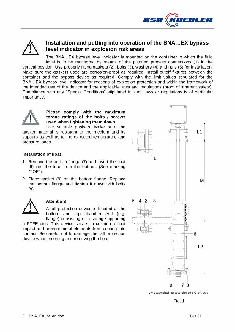
Installation and putting into operation of the BNA…EX bypass level indicator in explosion risk areas
The BNA…EX bypass level indicator is mounted on the container in which the fluid level is to be monitored by means of the planned process connections (1) in the
vertical position. Use properly fitting gaskets (2), bolts (3), washers (4) and nuts (5) for installation. Make sure the gaskets used are corrosion-proof as required. Install cutoff fixtures between the container and the bypass device as required. Comply with the limit values stipulated for the BNA…EX bypass level indicator for reasons of explosion protection and within the framework of the intended use of the device and the applicable laws and regulations (proof of inherent safety). Compliance with any "Special Conditions" stipulated in such laws or regulations is of particular importance.
Please comply with the maximum torque ratings of the bolts / screws used when tightening them down. Use suitable gaskets. Make sure the
gasket material is resistant to the medium and its vapours as well as to the expected temperature and pressure loads.
Installation of float
1. Remove the bottom flange (7) and insert the float (6) into the tube from the bottom. (See marking "TOP").
2. Place gasket (9) on the bottom flange. Replace the bottom flange and tighten it down with bolts (8).
Attention!
A fall protection device is located at the bottom and top chamber end (e.g. flange) consisting of a spring supporting
a PTFE disc. This device serves to cushion a float impact and prevent metal elements from coming into contact. Be careful not to damage the fall protection device when inserting and removing the float.
6
9
1
3
7
245
8
M
L1
L2
L = Bottom dead leg dependent on S.G. of liquid
Fig. 1

15 / 21 OI_BNA_EX_pt_en.doc
Installation and putting into operation of the BNA…EX bypass level indicator, heated, double-walled version, in explosion risk areas
The bypass tube is also available in a heated, double-walled version, in which the bypass tube is surrounded by a second tube (heating jacket). A heat-carrying medium, heated liquid or heated steam can be pumped through the resulting double-mantle space through two connections. Stainless material qualities in accordance with the AD specification sheets are used for the higher temperatures to which this construction is exposed.
To eliminate the risk of explosion caused by the heating system, the following requirements apply to operation of the heating system and the heat-carrying medium:
1. The temperature of the heat-carrying medium must not exceed 80% of the ignition temperature of the stored material.
2. The equipment operator must ensure, by means of constant monitoring and operational checks, that the ignition temperature listed under item 1 is not exceeded. These monitoring and checking activities must also take temperature dynamics resulting from chemical reactions into consideration. For example, maintenance of the permissible temperature level can be ensured on the basis of saturated steam pressure or the boiling point of a liquid.

OI_BNA_EX_pt_en.doc 16 / 21
1
2
3
4 5
6 7
Installation of signal processing and display devices on the BNA…EX bypass level indicator in explosion risk areas
When attaching the signal processing and display devices (e.g. MG magnetic switch) to the BNA…EX bypass level indicator, the upper limit values of the field device and the BNA…EX bypass level indicator must be complied with within the framework of explosion protection (proof of inherent safety). Laws and guidelines applying to the use or intended application of the equipment must be complied with. Only signal processing and display device certified for the given application conditions according to ATEX may be connected. EEC type certifications must be complied with. Compliance with any "Special Conditions" stipulated therein is of particular importance.
Example of mounting ( Level Sensor MG... )
The description provided here must be considered as being a means of orientation for the mounting-on possibility provided by location-specific conditions. Please also refer to the assembly and operating instructions of the add-on equipment units
Use thightening straps or fastening clips to fasten the Sensor MG... to the base equipment unit (bypass chamber) Depending on the magnet system, the distance between the position sensor (magnet) and the Sensor MG... tube should not exceed 8 mm. It is not permissible to drill into or through the bypass tube or to weld it directly. Please note the material pairings.
Number of recommended mounting brackets or tightening straps
Distance centre-to-centre up to 1000mm 2 brackets Distance centre-to-centre above 1000mm add 1 bracket for each initial 1000mm The brackets must be fitted at equal distances along the entire length of the pipe.
1 Level Sensor MG... 2 tensioning straps 3 Magnetic roller display 4 Cheese-head screws or
similar 5 Spacers 6 Mounting clips 7 Mounting brackets
17 / 21 OI_BNA_EX_pt_en.doc
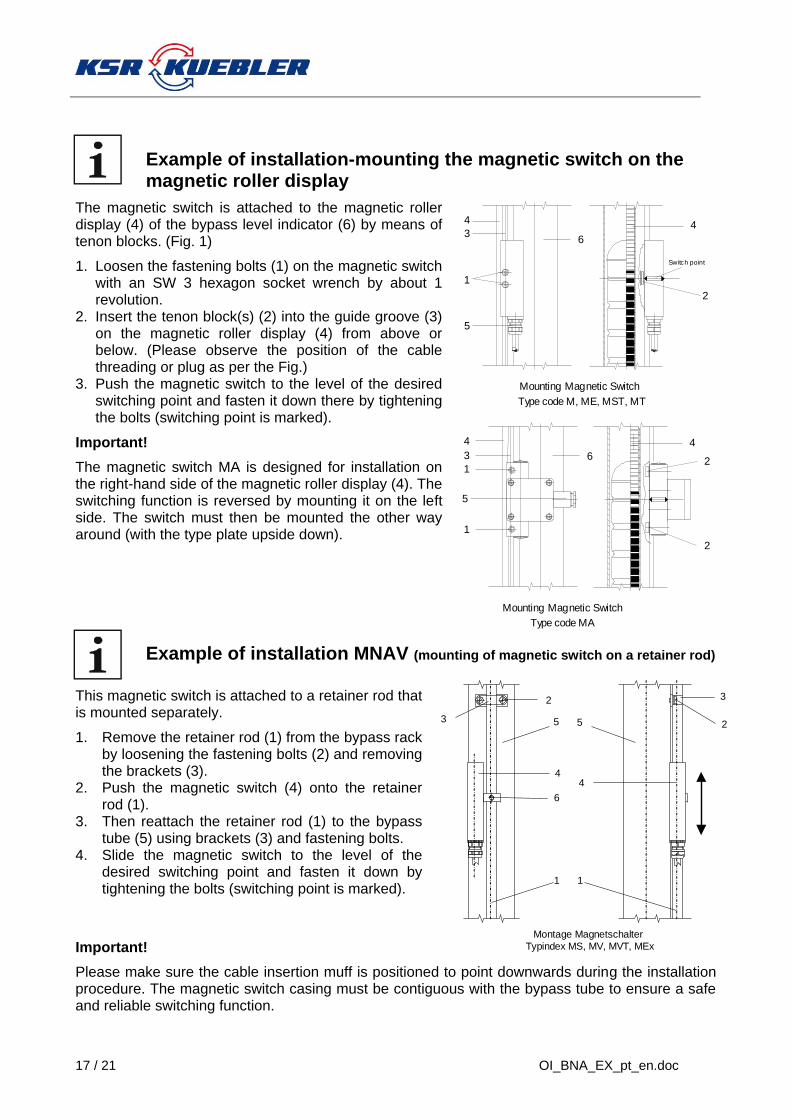
Example of installation-mounting the magnetic switch on the magnetic roller display
The magnetic switch is attached to the magnetic roller display (4) of the bypass level indicator (6) by means of tenon blocks. (Fig. 1)
1. Loosen the fastening bolts (1) on the magnetic switch with an SW 3 hexagon socket wrench by about 1 revolution.
2. Insert the tenon block(s) (2) into the guide groove (3) on the magnetic roller display (4) from above or below. (Please observe the position of the cable threading or plug as per the Fig.)
3. Push the magnetic switch to the level of the desired switching point and fasten it down there by tightening the bolts (switching point is marked).
Important!
The magnetic switch MA is designed for installation on the right-hand side of the magnetic roller display (4). The switching function is reversed by mounting it on the left side. The switch must then be mounted the other way around (with the type plate upside down).
Example of installation MNAV (mounting of magnetic switch on a retainer rod)
This magnetic switch is attached to a retainer rod that is mounted separately.
1. Remove the retainer rod (1) from the bypass rack by loosening the fastening bolts (2) and removing the brackets (3).
2. Push the magnetic switch (4) onto the retainer rod (1).
3. Then reattach the retainer rod (1) to the bypass tube (5) using brackets (3) and fastening bolts.
4. Slide the magnetic switch to the level of the desired switching point and fasten it down by tightening the bolts (switching point is marked).
Important!
Please make sure the cable insertion muff is positioned to point downwards during the installation procedure. The magnetic switch casing must be contiguous with the bypass tube to ensure a safe and reliable switching function.
1
4
3
5
Switch point
2
Mounting Magnetic Switch
Type code M, ME, MST, MT
4
6
3
4
1
1
2
2
Mounting Magnetic Switch
Type code MA
5
6
4
5 5
1 1
3
2
2
3
4
6
4
Montage Magnetschalter
Typindex MS, MV, MVT, MEx
OI_BNA_EX_pt_en.doc 18 / 21
Maintenance
BNA…EX bypass level indicators require no maintenance if used as intended. However, they must be subjected to a visual inspection within the framework of regular general inspections and must be included in container pressure tests.
Important!
The float is designed for the medium density level indicated on the type plate. Use in fluids with a different specific gravity results in measurement deviations.
The medium to be monitored should not contain any soiling or coarse particles. It should also not tend to crystallize out. The magnetic roller display and attached magnetic switch must be positioned and set using the enclosed float prior to installation. The bypass level indicator must not be installed near strong electromagnetic fields (at least 1 m away). Correct functioning of the bypass level indicator can only be guaranteed if original KSR Kuebler accessories and replacement parts are used.
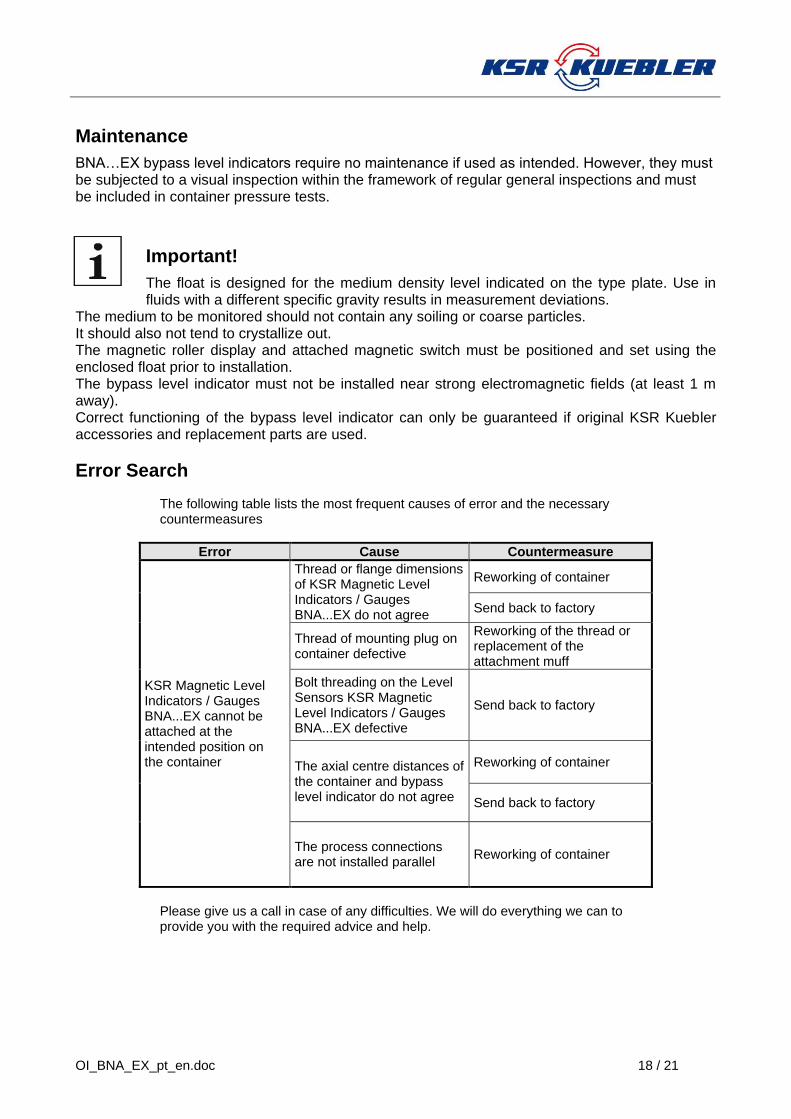
Error Search
The following table lists the most frequent causes of error and the necessary countermeasures
Error Cause Countermeasure
KSR Magnetic Level Indicators / Gauges BNA...EX cannot be attached at the intended position on the container
Thread or flange dimensions of KSR Magnetic Level Indicators / Gauges BNA...EX do not agree
Reworking of container
Send back to factory
Thread of mounting plug on container defective
Reworking of the thread or replacement of the attachment muff
Bolt threading on the Level Sensors KSR Magnetic Level Indicators / Gauges BNA...EX defective
Send back to factory
The axial centre distances of the container and bypass level indicator do not agree
Reworking of container
Send back to factory
The process connections are not installed parallel
Reworking of container
Please give us a call in case of any difficulties. We will do everything we can to provide you with the required advice and help.

19 / 21 OI_BNA_EX_pt_en.doc
Type Code BNA...EX
Type Code KSR Magnetic Level Indicators / Gauges
Basic type Code 1 Code 2 Code 3 Code 4 Code 5 Code 6 Code 7 Code 8
BNA- 25/ 16/ C- MG- M...- V/60,3x.2- MRA- 1/M../2- ZVSS250- EX
Code 8 EX ATEX Certificates EX DNV ATEX and DNV EX GL ATEX and GL
Code 7 Float type See Type Code Float
Code 6 Option Magnetic Switches, 1/... = quantity of the Magnetic switch ../M../... = see Typcode Magnetic switch .../.../1 = Length of Cable Magnetic switch (Only specification if option is available)
Code 5 Option Magnetic Roller Indicator MRA = Magnetic Roller Indicator ( < 180°C ambient temperature) MNAV = Magnetic Roller Indicator Edelstahl ( < 180°C ambient temperature) MRK = Magnetic Roller Indicator *( > 180°C ambient temperature) MNKV = Magnetic Roller Indicator Edelstahl *( > 180°C ambient temperature ) /SG with Scale (Aluminium engraved), /VSG with Scale (Stainless steel engraved) (Only specification if option is available) *Only BGUV magnetic switch can be used.
Code 4 Material and Chamber OD x Wall thickness in mm V/... = Stainless steel HC/... = Hastelloy C HB/... = Hastelloy B T/... = Titanium /.... = Chamber OD x Wall thickness (Ispecification 60/70 = heating jacket design)
Code 3 Distance between flange centres in mm
Code 2 Option Level Sensor see Typcode Level Sensor (Only specification if option is available)
Code 1 Process connection .../.../... = Flange (nominal size./ pressure rating./ Flange face) TC.../... = Triclamp (TC / nominal size./ pressure rating) MR.../... = Dairy fitting acc. to DIN 11851 (MR / nominal size./ pressure rating)
Thread or Welding stubs female M male N
size for example
Thread acc. to DIN G M or N .....“ GM 1“
Thread acc. to NPT NPT M or N .....“ NPTN 1“
Welding stubs S -- .....“ S 3/4" “
Basic type BNA

OI_BNA_EX_pt_en.doc 20 / 21
Type Code KSR Bypass Floats
Design with beads
Basic type Code 1 Code 2 Code 3
Z V SS 250
Code 3 Float length in mm
Code 2: Design with beads
Code 1:
Material V Stainless steel max. 20bar T Titanium max. 16 bar
Basic type Cylindrical floats
Design without beads
Basic type Code 1 Code 2 Code 3 Code 4 Code 5 Code 6 Code 7
Z V S 250/ 16/ 60/ 1000 ...
Code 7 magnet system
Code 6 density in kg/m³
Code 5 temperature in °C
Code 4 Nominal pressure in bar
Code 3
Float length in mm
Code 2: Design without beads
Code 1: Material V Stainless steel T Titanium HC Hastelloy HC HB Hastelloy HB
Basic type Cylindrical floats

21 / 21 OI_BNA_EX_pt_en.doc
Ignition protection
Ignition protection BNA ... EX without Magnetic roller display: II 1 G c T1...T6 Ignition protection BNA ... EX with Magnetic roller display : II 1/2 G c T1...T6 Float and bypass chamber zone 0 / Magnetic roller display zone 1
Temperatures
The maximum nominal pressure and temperature values listed on the type plate must not be exceeded.
Temperature class
Maximum process - temperature
BNA...EX
Maximum process - temperature
Maximum ambient -
temperature
Maximum ambient temperature at
processing and display equipment
MRA MRAN MNAV
MRK MNKV
T1 320°C ≤ 320°C
- 50... + 80°C
Avoid temperatures in excess of the maximum ambient temperature allowed for the installed processing and display equipment. See Mounting and Operating instruction - Description of processing and display devices
T2 240°C ≤ 180°C ≤ 240°C
T3 160°C ≤ 160°C ≤ 160°C
T4 108°C ≤ 108°C ≤ 108°C
T5 80°C ≤ 80°C ≤ 80°C
T6 68°C ≤ 68°C ≤ 68°C - 50... + 68°C
Pressure
test pressure acc. to AD regulation 2000
Nominal pressure in bar
minimum - maximum temperature range
Only if the bypass is made in accordance with PED 97/23/EEC (operating pressuring > 0.5 bar).
Tag No. :
PS. : PT. :
S. G. :
Chamber Mat. :
Float :
Serial No. :
BNA-
-EX
KEMA 02ATEX2106 X II 1 G c T1...T6 or II 1/2 G c T1...T6
____
0637
TS. :

OI_BNA_EX_pt_en.doc 22 / 21
KSR KUEBLER AG Adressen
KSR KUEBLER Niveau-Messtechnik AG Heinrich-Kuebler-Platz 1 D-69439 Zwingenberg/Neckar Tel: [+49] 06263 870 Fax: [+49] 06263/87-99 http://www.ksr-kuebler.com e-Mail: [email protected]