mil com 011
TRANSCRIPT
8/6/2019 Mil Com 011
http://slidepdf.com/reader/full/mil-com-011 1/6
A MODIFIED DIRECTIONAL FREQUENCY REUSE PLAN BASED ON CHANNEL
ALTERNATION AND ROTATION
Vincent A. NguyenPeng-Jun Wan
Ophir Frieder
Computer Science DepartmentIllinois Institute of TechnologyChicago, Illinois
[email protected], [email protected], and [email protected]
ABSTRACT
In previous work, we presented a novel Channel
Alternation and Rotation (CAR) scheme that coordinates
channel assignment with antenna directivities. In CAR,each cell type is allocated an extra channel set that provides network designer the flexibility to alternate and
rotate channels according to nearest front lobeinterference avoidant strategy to enhance co-channel
interference ratio (C/I). CAR relaxes the constraints
assumed in conventional reuse plans to allow deployment of smaller, unconventional reuse cluster sizes based on C/I
requirements, thus increases frequency reuse efficiency. In this paper, we present a new reuse plan in which 2 extra
channel sets are allocated to each cell type and assigned according to CAR strategy. This reuse plan, referred to as2x(3+2), increases channel capacity by 20% in
comparison with conventional 4x3 reuse plan while still provides signals above the minimum acceptable C/I
margin. 2x(3+2) reuse plan is simple and can be
implemented without costs.
INTRODUCTION
Unlike Omni-directional antenna which power radiatesequally in all directions, directional antennas project main beams power onto front lobe regions, thus side and back
lobes interference is reduced. To take advantages of theantenna directivities to enhance C/I, most cellular systems
employ three 1000to 120
0directional antennas at each base
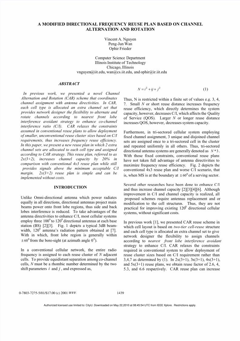
station (BS) [2][3]. Fig. 1 depicts a typical 3dB beam-
width, 1200
antenna’s radiation pattern obtained at [7].With in which, front lobe region is generally within
060± from the bore-sight (at azimuth angle 00).
In a conventional cellular network, the entire radio
frequency is assigned to each reuse cluster of N adjacent
cells. To provide equidistant separation among co-channelcells, N must be a rhombic number determined by the two
shift parameters i and j , and expressed as,
22 jiji N ++= (1)
Thus, N is restricted within a finite set of values e.g. 3, 4,
7. Small N or short reuse distance increases frequency
reuse efficiency, which directly determines the systemcapacity, however, decreases C/I, which affects the Quality
of Service (QOS). Larger N or longer reuse distanceincreases QOS, however, decreases system capacity.
Furthermore, in tri-sectored cellular system employing
fixed channel assignment, 3 unique and disjoined channelsets are assigned once to a tri-sectored cell in the cluster
and repeated uniformly in all others. Thus, tri-sectored
directional antenna systems are generally denoted as 3* N .
With those fixed constraints, conventional reuse planshave not taken full advantage of antenna directivities to
maximize frequency reuse efficiency. Fig. 2 depicts theconventional 4x3 reuse plan and worse C/I scenario, that
is, when MS is at the boundary at 060± of a serving sector.
Several other researches have been done to enhance C/Iand thus increase channel capacity [2][3][4][6]. Although
improvement in C/I and channel capacity is realized, all proposed schemes require antennas replacement and or
modification to the cell structures. Thus, they are not practical for improving existing 120
0directional cellular
systems, without significant costs.
In previous work [1], we presented CAR reuse scheme in
which cell layout is based on two-tier cell-reuse structureand each cell type is allocated an extra channel set to give
network designer the flexibility to assign channels
according to nearest front lobe interference avoidant strategy to enhance C/I. CAR relaxes the constraints
required in conventional system to allow deployment of reuse cluster sizes based on C/I requirement rather than3,4,7 as determined by (1). In 2x(3+1), 3x(3+1), 4x(3+1),
and 5x(3+1) reuse plans, we obtain reuse factor of 2.6, 4,
5.3, and 6.6 respectively. CAR reuse plan can increase
0-7803-7225-5/01/$17.00 (c) 2001 IEEE 1439
Authorized licensed use limited to: CityU. Downloaded on May 22,2010 at 08:45:54 UTC from IEEE Xplore. Restrictions apply.
8/6/2019 Mil Com 011
http://slidepdf.com/reader/full/mil-com-011 2/6
channel capacity up to 31.25% while still maintain C/Imargins comparable to targeted conventional N*3 reuse
plans. Furthermore, CAR uses existing directional antennainfrastructure, it truly does not impose any cost.
In CAR, each cell only uses 3 of the 4 allocated channelsets, thus the extra alternate channel set, if used and
carefully planned, can double the capacity any one sector.However, since the total number of channel sets in 3x(3+1)
and conventional 4x3 reuse plan are equal, without
employing alternate channel, the system capacities of thetwo schemes remain the same.
In this paper, we present a new reuse plan in which 2 extra
channel sets are allocated to each cell type and assigned according to CAR strategy to maximize frequency reuse
efficiency. This reuse plan, referred to as 2x(3+2),
increases channel capacity by 20% over conventional 4x3system while still provides signals at and above the
minimum acceptable C/I margin.
The remainder of this paper is organized as follows.Section II further describes how directional antenna
systems are exploited in CAR, and presents the 2x(3+2)
reuse plan. In Section III, we demonstrate the performance advantages of 2x(3+2) over conventional 4x3
and CAR 3x(3+1) reuse plan based on system capacity and
worse C/I. Finally, Section IV concludes this paper.
FREQUENCY REUSE PLANNING
A. Conventional 4x3 vs. CAR 3x(3+1) Reuse Plan
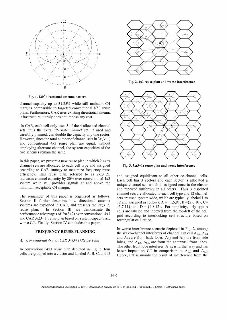
In conventional 4x3 reuse plan depicted in Fig. 2, four
cells are grouped into a cluster and labeled A, B, C, and D
and assigned equidistant to all other co-channel cells.
Each cell has 3 sectors and each sector is allocated a
unique channel set, which is assigned once in the cluster and repeated uniformly in all others. Thus 3 disjoined
channel sets are allocated to each cell type and 12 channelsets are used system-wide, which are typically labeled 1 to12 and assigned as follows: A = {1,5,9}, B ={2,6,10}, C=
{3,7,11}, and D = {4,8,12}. For simplicity, only type A
cells are labeled and indexed from the top-left of the cell
grid according to interlocking cell structure based onrectangular cell lattice.
In worse interference scenario depicted in Fig. 2, amongthe six co-channel interferers of channel 1 in cell A4,2, A2,4
and A6,4 are from back lobes, A0,2 and A8,2 are from side
lobes, and A2,0, A6,0, are from the antennas’ front lobes.
The other front lobe interferer, A10,0, is farther way and haslesser impact on C/I in comparison to A2,0 and A6,0.Hence, C/I is mainly the result of interference from the
Fig. 1. 1200
directional antenna pattern
Fig. 2. 4x3 reuse plan and worse interference
Fig. 3. 3x(3+1) reuse plan and worse interference
1440
Authorized licensed use limited to: CityU. Downloaded on May 22,2010 at 08:45:54 UTC from IEEE Xplore. Restrictions apply.

8/6/2019 Mil Com 011
http://slidepdf.com/reader/full/mil-com-011 3/6
two nearest front lobes interferers, specifically A2,0 and A6,0.
Unlike conventional tri-sectored antenna systems, in CAR,
each cell type is allocated an extra channel set used for channel alternation that results in k+1 sets per cell type
and )1( +k N sets system-wide. Thus, in 3x(3+1) reuse plan
depicted in Fig. 3, a total of 12 channel sets are used and assigned as follows: A = {1,4,7,10}, B = {2,5,8,11}, and C
= {3,6,9,12}. Since each cell is assigned only 3 of the 4
allocated sets, there are ( )4
3 = 4 unique patterns per cell
type, e.g., A1 = {1,4,7}, A2 = {1,4,10}, A3 = {1,7,10}, and
A4 = {4,7,10}. Therefore, the 3x(3+1) reuse plan consistsof repeating patterns of 12 cells and each channel is used 3times in the pattern, as illustrated in Fig 3.
Consider cell A0,0 on the top left corner, channel 1 (sector
1) points directly toward its nearest column-adjacent co-
channel cell A0,2, since channel 1 is replaced by channel
10, front lobe interference is avoided. Channel 10 is then
alternated by channel 1 in the next column-adjacent co-channel cell A0,4. Thus, 1 and 10 become alternating
channel pairs. Furthermore, channel 4 and 7 are alsorotated in each nearest column-adjacent co-channel cell,
interference is greatly reduced, as they become side lobe
interferers instead. Also notice that in subsequent row-adjacent co-channel cells, alternating channel pairs
become rotating channel pairs and vice versa. Thus,although channel 10 from the row-adjacent co-channel
cell, A3,1, points directly toward cell A0,0, however,channel 10 is not used in A0,0, there is no interference.
Due to channel rotation, channel 1 becomes back lobe
interferer; therefore, interference is negligible. Other adjacent co-channels are assigned likewise. Since front
lobe interference from nearest co-channel cells is avoided,interference is mainly from antennas’ side and back lobesthat are either reduced or negligible, and from antennas’
front lobes from second tier co-channels that are farther
away. Thus CAR schemes allow co-channels to be
assigned closer in comparison with their counterparts.
In worse interference scenario, also depicted in Fig. 3,
when MS is at the boundary of sector 4 in cell A6.4, amongthe six co-channel cells, due to channel alternation, A3,3
and A9,5 do not contains channel 4, thus there is no
interference; since channel 4 in A6,2 and A6,6 are rotated,they become back lobe and side lobe interferers; similarlyA3,5 and A9,3 also become back and side lobe interferers.All front lobe interferers, A0,4, A3,1, A12,2, and A12,6 are from
second tier co-channel cells which are farther away.
B. CAR 2x(3+2) Reuse Plan
Since TDMA system such as IS-136 requires 14 dB, tofurther enhance frequency reuse efficiency from 4x3 reuse
plan, in this paper, we present a reuse plan in which the
number of cell type is reduced to 2 and the number of
alternate channels is increased to 2 to a total of 5 channelsets per cell type and 10 channel sets system-wide. Thisscheme results in a novel reuse plan referred to as 2x(3+2).
Based on channel separation factor N, the channel
allocations are as follows: A = {1,3,5,7,9}, and B ={2,4,6,8,10}.
C. CAR 2x(3+2) Algorithm
To simplify 2x(3+2) channel assignment algorithm, we
again employ a rectangular cell-lattice ],[ k j I indexed
according to interlocking rows and columns starting fromthe top left of the grid, e.g. j =0,k=0.
1. Divide the available channels into 10 channel sets and
allocate to each cell-type as illustrated in Table I.
2. Start from the left column of cell-type I; For I = A to Ba) Label 5 channel sets allocated to type I cell as {C1,
C2, C3, C4, C5} b) Assign the first 3 channels to each sector of the
first cell of type I counter-clockwise starting from bottom to side and top sector, which are denoted
f2100, f90
0, and f330
0based on antenna’s direction
shown in Fig. 4, respectively.
c) For each remaining type I cells in the same
column• Advance to next adjoined co-channel cell.• Assign previous (channel previously used in)
f900to current f210
0and previous f330
0to
current f900.
• If current f900 is C5 then assign C1 to f3300,
else assign the next channel in sequence.
d) For each subsequent column of type I cells• Move to first cell on the top of the column.• Assign previous column adjacent f330
0to
current f2100
• If current f2100 is C5 then assign C1 to f900,
else assign the subsequent channel to f900.• If current f90
0is C5 then assign C1 to f330
0,
else assign the next channel to f3300
• Repeat step c.
Applying the above algorithm, we obtain 2x(3+2) reuse plan depicted in Fig. 5. This reuse plan consists of
repeating patterns of 10 cells which are as follows: A1 =
{1,3,5}, A2 = {3,5,7}, A3 = {5,7,9}, A4 = {7,9,1}, and A5 ={9,1,3} and B1 = {2,4,6}, B2 = {4,6,8}, B3 = {6,8,10}, B4
= {8,10,2}, and B5 = {10,2,4}. Table 1 summarizes the
1441
Authorized licensed use limited to: CityU. Downloaded on May 22,2010 at 08:45:54 UTC from IEEE Xplore. Restrictions apply.

8/6/2019 Mil Com 011
http://slidepdf.com/reader/full/mil-com-011 4/6
channel allocation and assignment of the three schemesdiscussed above for comparisons.
Note that in 2x(3+2), the same channel sets are repeated inadjoined co-channel cells; however, since they all point atdifferent directions, a back lobe co-channel separation
equal R is obtained and thus interference is minimal. Yet,
to further minimize interference, we suggest usingdirectional antennas with high front-to-back ratio to
maximally suppress side and back lobe radiation.
PERFORMANCE EVALUATION
In 2x(3+2), each channel is used 3 times in the repeating
pattern, thus the actual reuse factor for 2x(3+2) reuse plan
labeled car N generalized in [1] as,
j
xk N N car
)( += (2)
where j is the number of times the same channel set is
repeated in the pattern. Thus the reuse factor for 2x(3+2)
is 3.3 in comparison with reuse factor N=4 in 4x3 and 3x(3+1).
To determine its performance, worse interference scenario
is assumed. Thus C/I for user located at the fringe of a
sector is considered and provided in [1] as,
∑=
−
=
n
i
y
ii
R
DG
G
I
C
1
0
)(
)(log10
θ
θ (3)
where R is the radius of the cell and also the distance from
MS to the serving BS, normalized to 1; i D is the distance
from MS to thi co-channel BS; n is the number of co-
channel interferers, and γ is the path loss exponent set
equal to 4; )( 0θ G and )(θ iG are antenna gains by MS
from the serving BS and fromth
i co-channel BS at angle
iθ with respect to antenna bore-sight (at 00) respectively,
and expressed in decibels as,
( )( )
1010dBiG
iGθ
θ = (4)
In our analysis, we include all co-channel interferers fromadjacent co-channel cells and all second and third tier frontlobe and side lobe interferers that interference may be
significant, generally when i D < 7R and iθ <900.
However, we exclude and assume no shadowing effect.On the other hand, we also omit antenna down tiltingfactor, which can increase C/I by several dB. In
conventional plans where channels are assigned uniformlysystem-wide, thus, worse interference is theoretically the
same for all sectors and corners. However, in 2x(3+2),
due to channel rotation and channel assignment, which are based on antenna directions, some corners and sectors
CellType
Reuse Plan
A B C D
4x3 1,5,9 2,6,9 3,7,11 4,8,12
3x(3+1) 1,4,7,10 2,5,8,11 3,6,9,12
Pattern1 1,4,7 2,5,8 3,6,9
Pattern2 1,4,10 2,5,11 3,6,12
Pattern3 1,7,10 2,8,11 3,9,12
Pattern4 4,7,10 5,8,11 6,9,12
2x(3+2) 1,3,5,7,9 2,4,6,8,10
Pattern1 1,3,5 2,4,6
Pattern2 1,3,9 2,4,10
Pattern3 1,7,9 2,8,10
Pattern4 3,5,7 4,6,8
Pattern5 5,7,9 6,8,10
Table 1. Channel allocation
Fig. 4. Sector Orientations
Fig. 5. Channel assignment and reuse cluster in
2x(3+2)
1442
Authorized licensed use limited to: CityU. Downloaded on May 22,2010 at 08:45:54 UTC from IEEE Xplore. Restrictions apply.
8/6/2019 Mil Com 011
http://slidepdf.com/reader/full/mil-com-011 5/6
within the cell are different. Therefore, we compute C/I
for both corners of each sector.
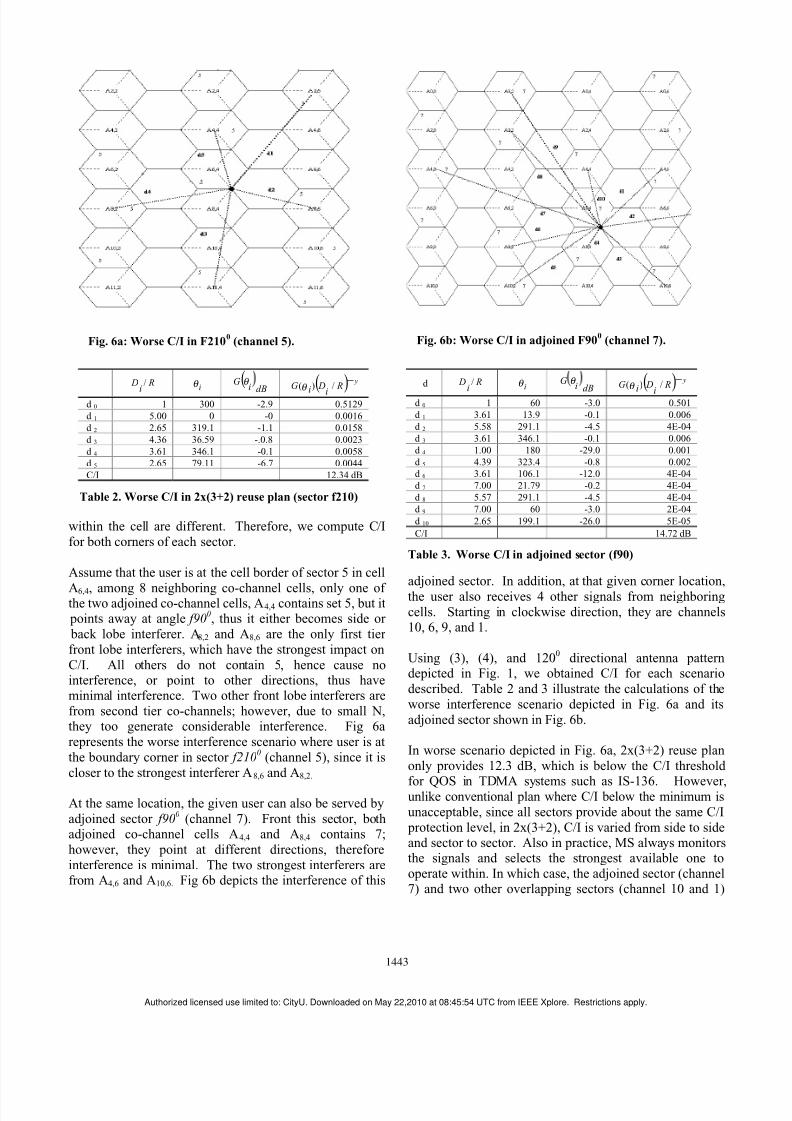
Assume that the user is at the cell border of sector 5 in cell
A6,4, among 8 neighboring co-channel cells, only one of the two adjoined co-channel cells, A4,4 contains set 5, but it points away at angle f90
0, thus it either becomes side or
back lobe interferer. A8,2 and A8,6 are the only first tier
front lobe interferers, which have the strongest impact on
C/I. All others do not contain 5, hence cause nointerference, or point to other directions, thus haveminimal interference. Two other front lobe interferers are
from second tier co-channels; however, due to small N,they too generate considerable interference. Fig 6a
represents the worse interference scenario where user is at
the boundary corner in sector f2100(channel 5), since it is
closer to the strongest interferer A8,6 and A8,2.
At the same location, the given user can also be served by
adjoined sector f900
(channel 7). Front this sector, bothadjoined co-channel cells A4,4 and A8,4 contains 7;
however, they point at different directions, therefore
interference is minimal. The two strongest interferers arefrom A4,6 and A10,6. Fig 6b depicts the interference of this
adjoined sector. In addition, at that given corner location,the user also receives 4 other signals from neighboring
cells. Starting in clockwise direction, they are channels10, 6, 9, and 1.
Using (3), (4), and 1200
directional antenna patterndepicted in Fig. 1, we obtained C/I for each scenario
described. Table 2 and 3 illustrate the calculations of the
worse interference scenario depicted in Fig. 6a and its
adjoined sector shown in Fig. 6b.
In worse scenario depicted in Fig. 6a, 2x(3+2) reuse plan
only provides 12.3 dB, which is below the C/I threshold
for QOS in TDMA systems such as IS-136. However,unlike conventional plan where C/I below the minimum is
unacceptable, since all sectors provide about the same C/I
protection level, in 2x(3+2), C/I is varied from side to sideand sector to sector. Also in practice, MS always monitorsthe signals and selects the strongest available one to
operate within. In which case, the adjoined sector (channel7) and two other overlapping sectors (channel 10 and 1)
d R
i
D / iθ
dBi
G θ
( )
y R
i D
iG
−/)(
θ
d 0 1 60 -3.0 0.501
d 1 3.61 13.9 -0.1 0.006
d 2 5.58 291.1 -4.5 4E-04
d 3 3.61 346.1 -0.1 0.006
d 4 1.00 180 -29.0 0.001
d 5 4.39 323.4 -0.8 0.002
d 6 3.61 106.1 -12.0 4E-04
d 7 7.00 21.79 -0.2 4E-04
d 8 5.57 291.1 -4.5 4E-04
d 9 7.00 60 -3.0 2E-04
d 10 2.65 199.1 -26.0 5E-05
C/I 14.72 dB
Table 3. Worse C/I in adjoined sector (f90)
R
i
D / i
θ (dBi
G θ
( ) y
Ri
Di
G−
/)(θ
d 0 1 300 -2.9 0.5129
d 1 5.00 0 -0 0.0016
d 2 2.65 319.1 -1.1 0.0158
d 3 4.36 36.59 -.0.8 0.0023
d 4 3.61 346.1 -0.1 0.0058
d 5 2.65 79.11 -6.7 0.0044
C/I 12.34 dB
Table 2. Worse C/I in 2x(3+2) reuse plan (sector f210)
Fig. 6a: Worse C/I in F2100
(channel 5). Fig. 6b: Worse C/I in adjoined F900
(channel 7).
1443
Authorized licensed use limited to: CityU. Downloaded on May 22,2010 at 08:45:54 UTC from IEEE Xplore. Restrictions apply.
8/6/2019 Mil Com 011
http://slidepdf.com/reader/full/mil-com-011 6/6
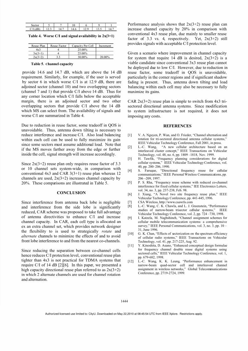
provide 14.6 and 14.7 dB, which are above the 14 dBrequirement. Similarly, for example, if the user is served
by sector 6 in which worse C/I is at 12.9 dB, there are
adjoined sector (channel 10) and two overlapping sectors
(channel 7 and 1) that provide C/I above 14 dB. Thus for any corner location which C/I falls below the acceptablemargin, there is an adjoined sector and two other
overlapping sectors that provide C/I above the 14 dBwhich MS can select from. The availability of signals and
worse C/I are summarized in Table 4.
Due to reduction in reuse factor, some tradeoff in QOS is
unavoidable. Thus, antenna down tilting is necessary toreduce interference and increase C/I. Also load balancing
within each cell can be used to fully maximize its gainsince some sectors must assume additional load. Note that
if the MS moves farther away from the edge or further
inside the cell, signal strength will increase accordingly.
Since 2x(3+2) reuse plan only requires reuse factor of 3.3or 10 channel sets system-wide, in comparison with
conventional 4x3 and CAR 3(3+1) reuse plan whereas 12channels are used, 2x(3+2) increases channel capacity by
20%. These comparisons are illustrated in Table 5.
CONCLUSION
Since interference from antenna back lobe is negligibleand interference from the side lobe is significantly
reduced, CAR scheme was proposed to take full advantage
of antenna directivities to enhance C/I and increase
channel capacity. In CAR, each cell type is allocated anex an extra channel set, which provides network designer the flexibility to is used to strategically rotate and
alternate channels to minimize the effects of and to avoid front lobe interference to and from the nearest co-channels.
Since reducing the separation between co-channel cellshence reduces C/I protection level, conventional reuse plan
tighter than 4x3 is not practical for TDMA systems thatrequire C/I of 14 dB [2][6]. In this paper, we presented a
high capacity directional reuse plan referred to as 2x(3+2)in which 2 alternate channels are used for channel rotation
and alternation.
Performance analysis shows that 2x(3+2) reuse plan canincrease channel capacity by 20% in comparison with
conventional 4x3 reuse plan, due mainly to smaller reuse
factor of 3.3 vs. 4, respectively. Yet, 2x(3+2) still
provides signals with acceptable C/I protection level.
Given a scenario where improvement in channel capacity
for system that require 14 dB is desired, 2x(3+2) is a
viable candidate since conventional 3x3 reuse plan cannot be deployed due to low C/I. However, due to reduction in
reuse factor, some tradeoff in QOS is unavoidable, particularly in the corner regions and if significant shadow
fading is present. Thus, antenna down tilting and load balancing within each cell may also be necessary to fully
maximize its gains.
CAR 2x(3+2) reuse plan is simple to switch from 4x3 tri-
sectored directional antenna systems. Since modificationto system infrastructure is not required, it does not
imposing any costs.
REFERENCES
[1] V. A. Nguyen, P. Wan, and O. Frieder, “Channel alternation and rotation for tri-sectored directional antenna cellular systems,”IEEE Vehicular Technology Conference, Fall 2001, in press.
[2] L.-C. Wang, “A new cellular architecture based on aninterleaved cluster concept,” IEEE Transactions on Vehicular Technology, vol. 48, no. 6, pp. 1809 –1818, Nov. 1999.
[3] H. Tawfik, “Frequency planning considerations for digital
cellular systems,” IEEE Vehicular Technology Conference, vol.
40, pp. 200–206, 1990.[4] S. Faruque, “Directional frequency reuse for cellular
communications,” IEEE Personal Wireless Communications, pp.
206 –209, 1997.
[5] P. S. Rha, “Frequency reuse scheme with reduced co-channelinterference for fixed cellular systems,” IEE Electronics Letters,vol. 34, no. 3, pp. 237-238, Feb. 98.
[6] J. Xiang, “A Novel two site frequency reuse plan,” IEEEVehicular Technology Conference, pp. 441-445, 1996.
[7] CSA Wireless, http://www.csawrls.com[8] L.-C. Wang, C. K. Chawla, and L. J. Greenstein, “Performance
studies of narrow-beam trisector cellular systems,” IEEEVehicular Technology Conference, vol. 2, pp. 724 –730, 1998.
[9] I. Katzela, M. Naghshineh, “Channel assignment schemes for
cellular mobile telecommunication systems: a comprehensive
survey,” IEEE Personal Communications, vol. 3, no. 3, pp. 10 – 31, June 1996.
[10] G. K. Chan, “Effects of sectorization on the spectrum efficiency
of cellular radio systems,” IEEE Transactions on Vehicular
Technology, vol. 41, pp. 217-225, Aug. 92.
[11] Y. Kinoshita, D. Asano, “Enhanced conceptual design formulaefor frequency channel double reuse digital systems usingsectored cells,” IEEE Vehicular Technology Conference, vol. 1,
pp. 679-682, 1998.
[12] L.-C. Wang, K. K. Leung, “Performance enhancement innarrow-beam quad-sector cell and interleaved channelassignment in wireless networks,” Global TelecommunicationsConference, pp. 2719-2724, 1999.
Reuse Plan Reuse Factor Capacity Per Cell Increment
4x3 4 25.00%
3x(3+1) 4 25.00%
2x(3+2) 3.3 30.00% 20.00%
Table 5. Channel capacity
Sector 5 7 10 6 9 1
C/I (dB) 12.3 14.7 14.6 12.9 13.5 14.7
Table 4. Worse C/I and signal availability in 2x(3+1)
1444
A h i d li d li i d Ci U D l d d M 22 2010 08 45 54 UTC f IEEE X l R i i l