manual uniclave 77 - frank's hospital workshop · página 1 de 25 a. j. costa (irmãos) lda....
TRANSCRIPT

Página 1 de 25 A. J. COSTA (Irmãos) Lda. 1953/2003 50 Anos ao Serviço Médico-Hospitalar Estrada da Ligeiras . Alto da Bela Vista . 2735-337 Cacém . Portugal . E-mail: [email protected]
Tel. Geral (+351) 214 266 500 . Fax(+351)214 262 421 Tel. Dep. Com [Eliwell, Dungs] (+351)214 266 504 Tel. Assitência Técnica (+351)214 266 502 Tel. Dep. Com. Equip. Méd. Hosp. (+351)214 266 505 Tel. Aprovisionamentos (+351)214 266 503 Tel. Dep. Com. [Sihi, Busch] (+351)214 266 508 . Fax (+351)214 266 506
OPERATING
MANUAL
A. J. COSTA (Irmãos) Lda. - Medical and Hospitalary Service Estrada da Ligeiras . Alto da Bela Vista . 2735-337 Cacém . Portugal .
Page 2 of 25
E-mail: [email protected] MO-002/03 E
INDEX:
1 SAFETY MEASURES ...................................................................................................... 3
2 WARRANTY ..................................................................................................................... 4
3 GENERAL DESCRIPTION OF UNICLAVE 77................................................................. 6
4 UNICLAVE 77 CYCLE INSTRUCTIONS ......................................................................... 7
5 STERILIZATION TYPICAL DIAGRAMS .......................................................................... 8
6 OPERATING INSTRUCTIONS ........................................................................................ 9
7 DIMENSION CHARTS ................................................................................................... 13
8 INSTALLATION INSTRUCTIONS .................................................................................. 14
8.1 PRECAUTIONS ON INSTALLATION ...................................................................... 14
8.2 INSTALLATION REQUIREMENTS ......................................................................... 14
9 EQUIPMENT INSTALLATION ....................................................................................... 15
9.1 ELECTRICAL CONNECTION ................................................................................. 15
10 MAINTENANCE ............................................................................................................. 16
10.1 MAINTENANCE SCHEDULE .................................................................................. 16
10.1.1 DAILY ............................................................................................................... 16
10.1.2 WEEKLY .......................................................................................................... 16
10.1.3 MONTHLY ........................................................................................................ 16
10.1.4 ANNUALLY ...................................................................................................... 16
10.2 CHECKING THE PRESSURE/TEMPERATURE RATIO ......................................... 17
10.3 VACUUM TEST ....................................................................................................... 19
10.4 TEMPERATURE CONTROLLER TEST - AT SEA LEVEL ...................................... 19
10.5 FUNCTIONING OF THE SAFETY PRESSURE SWITCH ....................................... 19
10.6 ELECTRICITY ......................................................................................................... 20
10.7 CHECKING OF THE WATER OUTAGE SAFETY DEVICE .................................... 20
10.8 DRAINAGE FILTER CLEANING ............................................................................. 21
11 TROUBLESHOOTING ................................................................................................... 21
12 LIST OF COMPONENTS ............................................................................................... 23
13 TECHNICAL FEATURES ............................................................................................... 24
14 SCHEMATICS ................................................................................................................ 25
14.1 MECHANICAL SCHEMATIC ................................................................................... 25
14.2 ELECTRIC SCHEMATIC ......................................................................................... 25

A. J. COSTA (Irmãos) Lda. - Medical and Hospitalary Service Estrada da Ligeiras . Alto da Bela Vista . 2735-337 Cacém . Portugal .
Page 3 of 25
E-mail: [email protected] MO-002/03 E
1 SAFETY MEASURES
These instructions for use should be read prior to Uniclave 77 process of installation. In this
way, not only is the machine protected against possible failure, as errors on misuse are
avoided.
Use Uniclave 77 solely for the referred purposes in this instructions manual. The maker
cannot be held responsible for any kind of malfunction or damage caused by misuse of this
equipment.
The Uniclave 77 must not be installed where a risk of explosion may exist.
Uniclave 77 electrical security is only guaranteed if the equipment is grounded. The maker
does not take responsibility in any malfunction, failure or interruption in the ground conductor.
When carrying any kind of repair work, Uniclave 77 should be unplugged from its power
supply; by disconnecting its circuit breaker.
Do not wash Uniclave 77’s exterior with water or corrosive/abrasive products.
Do not allow children or uninformed personnel to use Uniclave 77.

A. J. COSTA (Irmãos) Lda. - Medical and Hospitalary Service Estrada da Ligeiras . Alto da Bela Vista . 2735-337 Cacém . Portugal .
Page 4 of 25
E-mail: [email protected] MO-002/03 E
2 WARRANTY
All products supplied by A.J.Costa (Irmãos) Lda, are fully tested, in site, before shipment to
our clients. Each machine is subject to all operational tests in our rehearsal room, during
which a full set of validation cycles are performed.
Any damaged component due to manufacture or assembly defect, within twelve months from
the date of shipment from our factory, is covered in this warranty. All defective components
should be sent to our factory for inspection and replacement. The replacement component
will be sent, free from charges, to the original delivery address.
The shipment of the component(s) will be carried out by postal mail or normal freight.
Replaced components shall remain with A.J.Costa (Irmãos) Lda.
A.J.Costa (Irmãos) Lda, assures maintenance and service, except for labor costs which are
not included. We reserve the right to charge for labor and transportation costs.
Maintenance and service may only be carried out by A.J.Costa (Irmãos) Lda, or by certified
representatives for such services.
It should be noted that sometimes there is a considerable lapse of time until the equipment’s
set in use, which may cause problems outside our control.
It is important that the equipment remains protected and that the reservoir lids remain closed.
In any other way problems and premature damage may arise caused by entry and deposition
of foreign particles, dirt, dust, etc., namely in the deposits, pumps, steam generator, valves or
electrical components.
Regarding the installation there should be taken special precautions so to assure that the
plumbing residue, filings from pipes and threads, debris from sealers or fillings, do not enter
the components or fluid circuits of Uniclave 77. After finalizing all plumbing work, all the

A. J. COSTA (Irmãos) Lda. - Medical and Hospitalary Service Estrada da Ligeiras . Alto da Bela Vista . 2735-337 Cacém . Portugal .
Page 5 of 25
E-mail: [email protected] MO-002/03 E
pipes should be cleansed, by flushing pressurized water through them and into the sewer,
before connecting them to Uniclave 77.
Periodically determine the hardness of the water that is used in Uniclave 77 for the adverse
consequences caused by lime deposits and/or foreign particles may not be imputed to
A.J.Costa (Irmãos) Lda.
The non-compliance to this set of precautions and basic procedures, will nullify this
warranty.

A. J. COSTA (Irmãos) Lda. - Medical and Hospitalary Service Estrada da Ligeiras . Alto da Bela Vista . 2735-337 Cacém . Portugal .
Page 6 of 25
E-mail: [email protected] MO-002/03 E
3 GENERAL DESCRIPTION OF UNICLAVE 77
The vertical sterilizers, of the Uniclave 77 series, are designed for the sterilization of surgical
instruments, liquids, rubber, and laboratory materials.
The sterilizer is top-loaded, using specially designed steel baskets.
The Uniclave 77 has variable controls that offer a range of cycles with temperatures varying
between 100ºC and 135ºC and sterilization times between 0 and 120 minutes.
Drying is improved by vacuum produced by thermal shock, using the water coil or by slow
exhaust.
Manufacture is standardized with two cylindrical sterilization chambers of 45 x 80 cm and 50
x 80, diameter x depth respectively (usable areas). The electric connection can be 3-phase
(400 VAC) or 1-phase (230 VAC).
The chamber and lid as well as the front and side panels are constructed in stainless steel.
The lid is closed by means of several stainless steel screws and threaded handles.
The hermetic sealing between the chamber and the lid is achieved by the compression of a
silicone rubber ring.
In all the sterilizer models constructed by A.J.Costa (Irmãos) Lda, the sterilizing chambers
are tested both hydraulically and with steam during assembly.

A. J. COSTA (Irmãos) Lda. - Medical and Hospitalary Service Estrada da Ligeiras . Alto da Bela Vista . 2735-337 Cacém . Portugal .
Page 7 of 25
E-mail: [email protected] MO-002/03 E
4 UNICLAVE 77 CYCLE INSTRUCTIONS
The vertical sterilizers of the Uniclave series are used in the sterilization of a wide variety of
materials like surgical instruments, rubbers, plastics, laboratory material, etc.
The use of Uniclave 77 in a laboratory should be performed by qualified technicians or by
the direct supervision of a qualified technician, likewise should be this technician to establish
the appropriate parameters for each material or load type.
A.J. Costa (Irmãos), Lda recommends that the following parameters be used for the
sterilization of typical loads:
Thermo-sensitive materials (rubber, plastic, diathermy pencils)
- Sterilization temperature: 121º C
- Minimum sterilization time of 20 minutes
- The drying procedure should be executed as specified in “Operating
instructions”
The total time of this sterilization cycle is approximately 60 minutes.
Surgical instruments
- Sterilization temperature: 134º C
- Minimum sterilization time of 5 minutes
- The drying procedure should be executed as specified in “Operating
instructions”
The total time of this sterilization cycle is approximately 45 minutes.

A. J. COSTA (Irmãos) Lda. - Medical and Hospitalary Service Estrada da Ligeiras . Alto da Bela Vista . 2735-337 Cacém . Portugal .
Page 8 of 25
E-mail: [email protected] MO-002/03 E
5 STERILIZATION TYPICAL DIAGRAMS
TYPICAL DIAGRAM FOR THE STERILIZATION OF SURGICAL INSTRUMENTS
TYPICAL DIAGRAM FOR THE STERILIZATION OF LABORATORY UTENSILS

A. J. COSTA (Irmãos) Lda. - Medical and Hospitalary Service Estrada da Ligeiras . Alto da Bela Vista . 2735-337 Cacém . Portugal .
Page 9 of 25
E-mail: [email protected] MO-002/03 E
6 OPERATING INSTRUCTIONS
Front and rear view of Uniclave 77
6
4
5
7
81
10
9
11
2
3
Front View Rear View
1 - Sterilizer drain 3/4” thread 6 - Thermal switch with display
2 - Water inlet connection with flexible
hose to 3/4” Male with shut off valve
7 - Three position switch
8 - Indication lights
3 - Power supply 9 - Condenser water tap
4 - Pressure/vacuum gauge 10 - Drying water tap
5 - Timer 11 - Drain tap

A. J. COSTA (Irmãos) Lda. - Medical and Hospitalary Service Estrada da Ligeiras . Alto da Bela Vista . 2735-337 Cacém . Portugal .
Page 10 of 25
E-mail: [email protected] MO-002/03 E
Operating instructions:
1. Make sure the “DRAIN” and “DRYING” taps are tightly closed.
2. Fill the sterilizer with water 2 cm above the level of the central resistance. Demineralised or
distilled water is recommended.
Inside view of Uniclave 77 chamber
3. Load the sterilizer with the material to be sterilized.
4. Close the lid of the sterilizer, by screwing the threaded handles.
HEATING ELEMENTS
TEMPERATURE PROBE
WATER OUTAGE SAFETY DEVICE PROBE
DRAIN
DRYING COIL

A. J. COSTA (Irmãos) Lda. - Medical and Hospitalary Service Estrada da Ligeiras . Alto da Bela Vista . 2735-337 Cacém . Portugal .
Page 11 of 25
E-mail: [email protected] MO-002/03 E
5. Set the required sterilization temperature, on the temperature controller and indicator,
located on the control panel.
6. Turn the three position main switch to the “ON” position. The green indicator “ON” will light
and a buzzer will sound.
7. Turn the clock to the required sterilization time. The buzzer will stop and the resistances
will start to heat up.
8. Open the “CONDENSER” tap slightly (just enough to condense the steam entering the
drain).
9. As soon as the required sterilisation temperature is reached, the red indicator
“STERILIZATION” will light and the sterilization timer will start counting.
10. At the end of the sterilization time, the buzzer will sound. Turn off the three-position
switch to “0” and the indicator lamps will go off. Slowly open the “DRAIN” tap.
11. Before the pressure vacuum gauge, located on the control panel, shows 0 bar, the
“CONDENSER” tap should be closed. Immediately afterwards, when 0 bar is reached,
close the “DRAIN” tap and open the “DRYING” tap for water to run in the coil for a period
of ± 20 min. (drying time).
12. At the end of the fore mentioned period, proceed as follows:
1. Close the “DRYING” tap.
2. Loosen the threaded handles that tighten the lid.
3. Turn the three-position switch to “VACUUM BREAK” position.
4. Open the lid, when the pressure vacuum gauge indicates 0 bar.

A. J. COSTA (Irmãos) Lda. - Medical and Hospitalary Service Estrada da Ligeiras . Alto da Bela Vista . 2735-337 Cacém . Portugal .
Page 12 of 25
E-mail: [email protected] MO-002/03 E
Notes:
In case of laboratory sterilization cycles, the drying phase may be not required. Simply ignore
instructions 11 and 12.
At the end of the sterilization cycle proceed as in 12.2, .3 and .4.
For very long sterilization cycles (laboratory), the input of water must be increased.
The difference between the required temperature and the attained temperature is ± 2°C.
The sterilization time is pre-programmed by the operator and automatically controlled. The
drying time is controlled solely by the operator.

A. J. COSTA (Irmãos) Lda. - Medical and Hospitalary Service Estrada da Ligeiras . Alto da Bela Vista . 2735-337 Cacém . Portugal .
Page 13 of 25
E-mail: [email protected] MO-002/03 E
7 DIMENSION CHARTS
Dimensions of the sterilizer Uniclave 77 and sterilization chamber.
1 - Sterilizer drain 3/4”
1A - Installation Drain 1 1/2” female at ground level
2 - Water connection flexible hose to 3/4” M tap on the wall
3 - Power supply
Chamber (Usable Dimensions [mm])
Ø 45 x 80 Ø 50 x 80
H (max) 1250
L (max) 790
P (max) 1000
A 75
B 175
C 100
D 930

A. J. COSTA (Irmãos) Lda. - Medical and Hospitalary Service Estrada da Ligeiras . Alto da Bela Vista . 2735-337 Cacém . Portugal .
Page 14 of 25
E-mail: [email protected] MO-002/03 E
8 INSTALLATION INSTRUCTIONS
The equipment installation should be accomplished with the help of the installation drawing,
which indicates the service area and the necessary connections of the equipment.
8.1 PRECAUTIONS ON INSTALLATION
It’s important to verify the safety regulations concerning the legal requirements on your
country regarding electric installation, pipefitting, drains, or any requirement specially
connected with the installation of this type of equipment.
8.2 INSTALLATION REQUIREMENTS
Prior to the installation of the Uniclave 77 be sure that all the necessary connections to the
equipment’s correct functioning are available, for that purpose consult the installation
drawing.
For the installation of the Uniclave 77, the following connections must be available:
Drain pipe, 1 ½ `` female connection at ground level
Electricity box at 1000 mm above the ground. 3-phase cable or 1-phase cable
(according to the selected model) capable of supporting 400 V AC or 230 V AC 50 Hz
+ Neutral and Ground (3x2,5+N2,5 ) with power supply according to the model, and a
differential protection of 300 mA.

A. J. COSTA (Irmãos) Lda. - Medical and Hospitalary Service Estrada da Ligeiras . Alto da Bela Vista . 2735-337 Cacém . Portugal .
Page 15 of 25
E-mail: [email protected] MO-002/03 E
9 EQUIPMENT INSTALLATION
When assembling the 3/4” brass elbow (A) to the drain of the sterilizer, it is recommended
that:
- Hold the tube (1) with a pipe
wrench so that the tubing inside
the machine is not twisted.
- Screw the elbow as shown by
the arrow (2).
Note: Make sure that minimum space for use and technical support is guaranteed. Make also
sure that the Uniclave is levelled.
9.1 ELECTRICAL CONNECTION
Make sure that the voltage, current, power supply and frequency characteristics are
compliant with your country electrical output.
To increase safety we advise connecting your equipment to a differential protection circuit
with a nominal current of 300mA.
Note: Electrical connections should always be performed by a qualified technician.

A. J. COSTA (Irmãos) Lda. - Medical and Hospitalary Service Estrada da Ligeiras . Alto da Bela Vista . 2735-337 Cacém . Portugal .
Page 16 of 25
E-mail: [email protected] MO-002/03 E
10 MAINTENANCE
10.1 MAINTENANCE SCHEDULE
10.1.1 Daily
Clean external panels with special cleaning product for stainless steel.
Clean internal chamber with special cleaning product for stainless steel.
10.1.2 Weekly
Check that indicating lamps are working.
Check Pressure/Temperature ratio during sterilization.
10.1.3 Monthly
Perform a vacuum test.
Clean drainage filter.
Test temperature controller.
Lubricate handles with non-melting grease (”Spanjard – Non-Melting Grease”).
Clean, check and replace purger, if necessary.
10.1.4 Annually
Check bacteriological filter and replace it
Check safety Pressure Switch operation
Measure electrical supply in each phase
Measure earth current
Check, clean and lubricate or replace if necessary:
- Electromagnetic valves
- Safety valve
- Drainage valve

A. J. COSTA (Irmãos) Lda. - Medical and Hospitalary Service Estrada da Ligeiras . Alto da Bela Vista . 2735-337 Cacém . Portugal .
Page 17 of 25
E-mail: [email protected] MO-002/03 E
Replace seals on both condensation and drying valve
Replace lid gasket
Check the water outage safety device
Replace the purger
ADVICES
1- If a problem occurs, the first step is to check the necessary elements for the correct
functioning of the equipment: whether they are in working order or faulty.
E.g.: Power supply, water...
2- Faults detected in the functioning of a component should be corrected.
E.g.: valves, filters, pressure switch and thermostat.
3- Tubing should be checked for possible leaks.
E.g.: drainage tube, steam...
4- The operating instructions should be followed.
5- In case of Maintenance Procedure, some tests, which may facilitate the diagnosis of faults,
are described.
E.g.: Vacuum test, test of pressure / thermostat
10.2 CHECKING THE PRESSURE/TEMPERATURE RATIO
This ratio check should be carried out in accordance with the table below (the table refers to
absolute pressures. 1 bar should be added to the pressure as read on the chamber’s gauge).
E.g.: When the pressure shown on the gauge is 1,1 bar, the absolute pressure is
approximately 2,1 bar and the temperature should be 121ºC.

A. J. COSTA (Irmãos) Lda. - Medical and Hospitalary Service Estrada da Ligeiras . Alto da Bela Vista . 2735-337 Cacém . Portugal .
Page 18 of 25
E-mail: [email protected] MO-002/03 E
PRESSURE/TEMPERATURE RATIO TABLE
C K BAR C K BAR
70 343.15 0.3116 110 383.15 1.432771 344.15 0.3253 111 384.15 1.481572 354.15 0.3396 112 385.15 1.531673 346.15 0.3543 113 386.15 1.583274 347.15 0.3696 114 387.15 1.636275 348.15 0.3855 115 388.15 1.690676 349.15 0.4019 116 389.15 1.745677 350.15 0.4189 117 390.15 1.803978 351.15 0.4365 118 391.15 1.862879 352.15 0.4547 119 392.15 1.923380 353.15 0.4736 120 393.15 1.985481 354.15 0.4931 121 394.15 2.049282 355.15 0.5133 122 395.15 2.114583 356.15 0.5342 123 396.15 2.181684 357.15 0.5557 124 397.15 2.250485 358.15 0.5780 125 398.15 2.321086 359.15 0.6011 126 399.15 2.393387 360.15 0.6249 127 400.15 2.467588 361.15 0.6495 128 401.15 2.543589 362.15 0.6749 129 402.15 2.621590 363.15 0.7011 130 403.15 2.701391 364.15 0.7281 131 404.15 2.783192 365.15 0.7561 132 405.15 2.867093 366.15 0.7849 133 406.15 2.952894 367.15 0.8146 134 407.15 3.04195 368.15 0.8453 135 408.15 3.13196 369.15 0.8769 136 409.15 3.22397 370.15 0.9094 137 410.15 3.31798 371.15 0.9430 138 411.15 3.41499 372.15 0.9776 139 412.15 3.513100 373.15 1.0133 140 413.15 3.614101 374.15 1.0500 141 414.15 3.717102 375.15 1.0878 142 415.15 3.823103 376.15 1.1267 143 416.15 3.931104 377.15 1.1668 144 417.15 4.042105 378.15 1.2080 145 418.15 4.155106 379.15 1.2504 146 419.15 4.271107 380.15 1.2941 147 420.15 4.389108 381.15 1.3390 148 421.15 4.510109 382.15 1.3852 149 422.15 4.634

A. J. COSTA (Irmãos) Lda. - Medical and Hospitalary Service Estrada da Ligeiras . Alto da Bela Vista . 2735-337 Cacém . Portugal .
Page 19 of 25
E-mail: [email protected] MO-002/03 E
10.3 VACUUM TEST
Switch the sterilizer off with the chamber at a vacuum of ≈ -0,9 bar and wait for one hour. If,
past that time, the pressure in the chamber is not between -0,9 and -0,85bar, this will indicate
that there is a leak in the chamber or in one of its components.
- Drainage valve
- Electromagnetic purging valve
- Electromagnetic airing valve
- Safety valve
- Gasket sealing
- Connections pieces
10.4 TEMPERATURE CONTROLLER TEST - AT SEA LEVEL
Fill the sterilizer with water 2 cm above the level of the temperature controller probe element.
- Set the controller to 110ºC
- Switch on the sterilizer (With the lid open) and wait for the water to start
boiling.
CONCLUSION: The temperature inside the chamber at this point is 100ºC and the
temperature controller should indicate between 98 and 102ºC. This is only valid at sea level.
10.5 FUNCTIONING OF THE SAFETY PRESSURE SWITCH
Raise the pressure inside the chamber and check that the pressure switch works at a
pressure of 2,5 bar ≈ 138ºC.

A. J. COSTA (Irmãos) Lda. - Medical and Hospitalary Service Estrada da Ligeiras . Alto da Bela Vista . 2735-337 Cacém . Portugal .
Page 20 of 25
E-mail: [email protected] MO-002/03 E
10.6 ELECTRICITY
Place an Ammeter on the measuring point. The following are acceptable values:
3F-230V-6000W / 3F-400V-6000W 1F-220V-6000W
R - 8 a 10 Amperes R - 26 a 28 Amp
S - 8 a 10 Amperes
T - 8 a 10 Amperes
GROUND – Up to 300 mA
This test can also be carried out using a pincer type Ammeter.
10.7 CHECKING OF THE WATER OUTAGE SAFETY DEVICE
Fill the sterilizer without fully covering the central heating element (about ½ covered) and
switch it on, following normal procedure.
The device should operate under these circumstances, and the central blue button should be
triggered.
The device can only be rearmed after cooling down, by pushing in the blue button with a
screwdriver.

A. J. COSTA (Irmãos) Lda. - Medical and Hospitalary Service Estrada da Ligeiras . Alto da Bela Vista . 2735-337 Cacém . Portugal .
Page 21 of 25
E-mail: [email protected] MO-002/03 E
10.8 DRAINAGE FILTER CLEANING
2- Retaining trap of impurities
3- Lid seal
4- Large lid
Periodically remove the filter lid (4), with dirt retaining mesh (2), wash thoroughly and
reassemble replacing the lid gasket (3).
If the mesh (2) is damaged, replace it with a new one.

A. J. COSTA (Irmãos) Lda. - Medical and Hospitalary Service Estrada da Ligeiras . Alto da Bela Vista . 2735-337 Cacém . Portugal .
Page 22 of 25
E-mail: [email protected] MO-002/03 E
11 TROUBLESHOOTING
Th
e A
uto
cla
ve
do
es
no
t s
wit
ch
on
Th
e r
eq
uir
ed
pre
ss
ure
is
no
t
rea
ch
ed
or
tak
es
to
o lo
ng
Te
rmin
ati
on
of
ste
rilis
ati
on
is
no
t
Sig
na
lle
d
Wa
ter
do
es
no
t d
rain
aw
ay
Te
mp
era
ture
an
d p
res
su
re d
o n
ot
co
rre
sp
on
d
Ab
no
rma
l D
ryin
g (
We
ak
va
cu
um
)
Le
ak
ag
e o
f L
id S
ea
l
On
e o
r m
ore
cir
cu
it b
rea
ke
rs a
re
trig
ge
red
Electrical circuit x x x
Drainage Valve and Filter x x x
Pressure switch and thermostat x x
Purging Valve and Purifier x x x
Heating Elements x
Safety valve x
"Shortage of Water" Indicator
light ONx
Buzzer x
Vacuum gauge x
Timer
Command Fuse x
Perform Vacuum Test x
See Operating Instructions x
Air in Chamber during
Sterilisationx x
Test pressure switch and
thermostatx
Lid Seal - Adjustment of Lid x
MALFUNCTION
CHECK
A. J. COSTA (Irmãos) Lda. - Medical and Hospitalary Service Estrada da Ligeiras . Alto da Bela Vista . 2735-337 Cacém . Portugal .
Page 23 of 25
E-mail: [email protected] MO-002/03 E
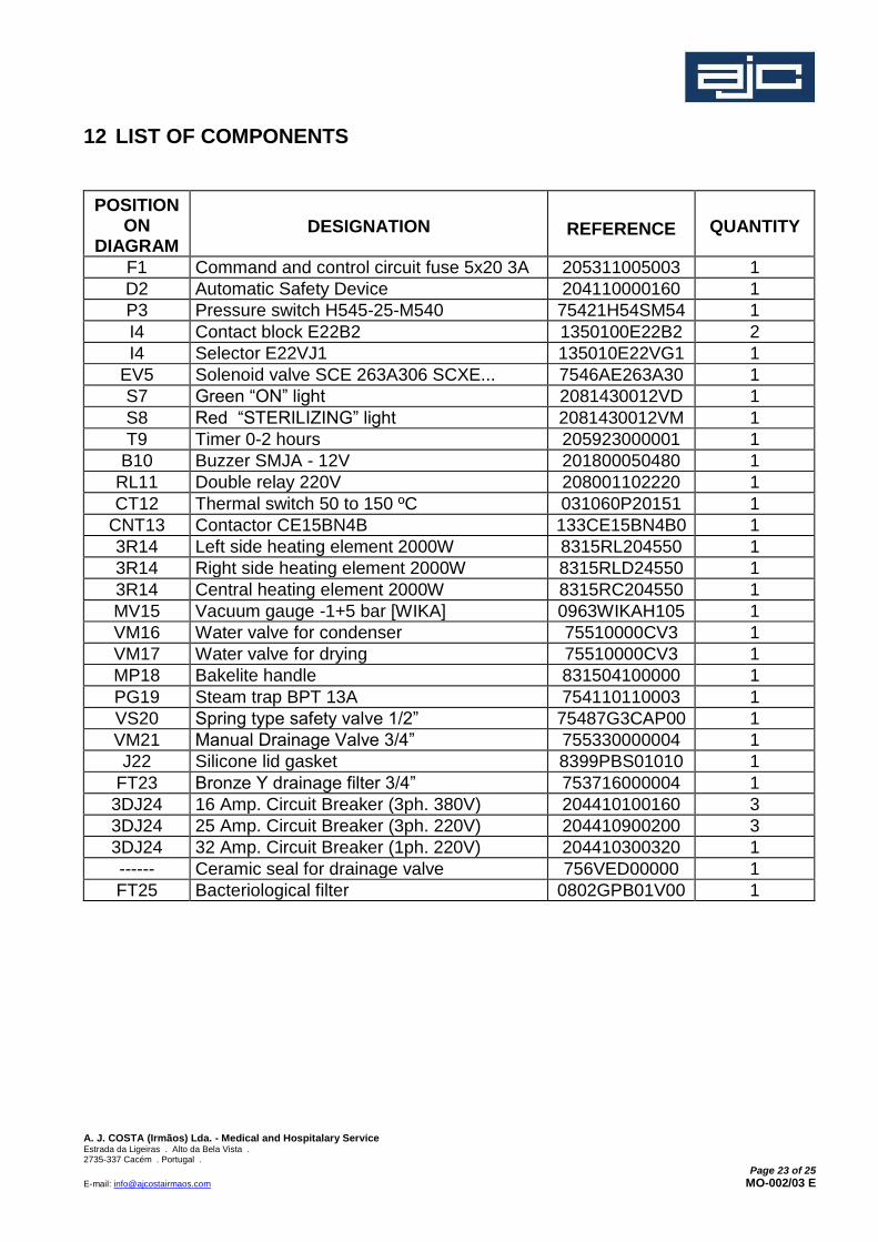
12 LIST OF COMPONENTS
POSITION ON
DIAGRAM
DESIGNATION
REFERENCE
QUANTITY
F1 Command and control circuit fuse 5x20 3A 205311005003 1
D2 Automatic Safety Device 204110000160 1
P3 Pressure switch H545-25-M540 75421H54SM54 1
I4 Contact block E22B2 1350100E22B2 2
I4 Selector E22VJ1 135010E22VG1 1
EV5 Solenoid valve SCE 263A306 SCXE... 7546AE263A30 1
S7 Green “ON” light 2081430012VD 1
S8 Red “STERILIZING” light 2081430012VM 1
T9 Timer 0-2 hours 205923000001 1
B10 Buzzer SMJA - 12V 201800050480 1
RL11 Double relay 220V 208001102220 1
CT12 Thermal switch 50 to 150 ºC 031060P20151 1
CNT13 Contactor CE15BN4B 133CE15BN4B0 1
3R14 Left side heating element 2000W 8315RL204550 1
3R14 Right side heating element 2000W 8315RLD24550 1
3R14 Central heating element 2000W 8315RC204550 1
MV15 Vacuum gauge -1+5 bar [WIKA] 0963WIKAH105 1
VM16 Water valve for condenser 75510000CV3 1
VM17 Water valve for drying 75510000CV3 1
MP18 Bakelite handle 831504100000 1
PG19 Steam trap BPT 13A 754110110003 1
VS20 Spring type safety valve 1/2” 75487G3CAP00 1
VM21 Manual Drainage Valve 3/4” 755330000004 1
J22 Silicone lid gasket 8399PBS01010 1
FT23 Bronze Y drainage filter 3/4” 753716000004 1
3DJ24 16 Amp. Circuit Breaker (3ph. 380V) 204410100160 3
3DJ24 25 Amp. Circuit Breaker (3ph. 220V) 204410900200 3
3DJ24 32 Amp. Circuit Breaker (1ph. 220V) 204410300320 1
------ Ceramic seal for drainage valve 756VED00000 1
FT25 Bacteriological filter 0802GPB01V00 1

A. J. COSTA (Irmãos) Lda. - Medical and Hospitalary Service Estrada da Ligeiras . Alto da Bela Vista . 2735-337 Cacém . Portugal .
Page 24 of 25
E-mail: [email protected] MO-002/03 E
13 TECHNICAL FEATURES
The difference between the required temperature and the reached temperature is 2 degrees
Celsius. The sterilization and drying times are programmed by the operator:
Uniclave 77
Ø 45 x 80 / Ø 50 x 80
Characteristics Standard Special Special
Power Supply 3F - 400VAC/50Hz 3F - 230VAC/50Hz 1F - 230VAC/50Hz
Voltage (V) 400 230 230
Intensity (A) 3 x 16A 3 x 16A 1 x 32A
Electric Cable 5G2,5 4G2,5 4G6
Electric Resistance 3 x 2000W 3 x 2000W 3 x 2000W
CONSUMPTION
Characteristics Uniclave 77
Ø 45 x 80
Uniclave 77
Ø 50 x 80
Electricity
2 kW when heating up to 134°C
0,25 kW during the 10 minutes
Sterilization at 134 °C
3 kW when heating up to 134°C
0,25 kW during the 10 minutes
Sterilization at 134 °C
Distilled Water 11 litres per cycle 20 litres per cycle

A. J. COSTA (Irmãos) Lda. - Medical and Hospitalary Service Estrada da Ligeiras . Alto da Bela Vista . 2735-337 Cacém . Portugal .
Page 25 of 25
E-mail: [email protected] MO-002/03 E
14 SCHEMATICS
14.1 MECHANICAL SCHEMATIC
The mechanical diagram has the following drawing code: 2.5710.1010
14.2 ELECTRIC SCHEMATIC
The electric diagram has the following drawing code, according to the model:
1-Phase : 230VAC/50Hz - 2.5710.1020
3-Phase : 400VAC/50Hz - 2.5710.1030
3-Phase : 230VAC/50Hz - 2.5710.1040