intermodal pulse dispersion in multimode optical fibres ... · pdf filerevista brasileira de...
TRANSCRIPT

Revista Brasileira de Física, Vol. 10, NP 3, 1980
Intermodal Pulse Dispersion in Multimode Optical Fibres and Its Measurement with a Nanosecond Test Facility
HARISH R. D. SUNAK and JOÃO BATISTA DE MELLO AYRES NETO
Instituto de .F/sica, Universidade Estadual de Campinas, 13 1(XI Campinas, SP, Brasil
Recebido em 10 de Fevereiro de 1980
We discuss pulse d ispers ion i n o p t i c a l f i b r e s and o u t l ine the
various mechanisms which con t r i bu te towards i t. The magnitude o f each
d ispers ion mcxhanism i n d i f f e r e n t types o f f i b r e s i s o u t l i n e d and i t s
e f f e c t on the: informat ion car ry i ng capaci t y d i scussed. A Nanosecond Test
Faci l i t y , f o r intermodal d ispers ion measurements i s discussed i n d e t a i l ,
together w i t h the procedure f o r i t s operat ion. Some r e s u l t s obtained
wi t h t h i s f a c i 1 i t y are i l lus t ra ted.
Discutimos a dispersão de pulsos em f i b r a s Ót icas e destaca-
mos os vãr ios mecanismos que contribuem para isso. Foram d i scutidos a in-
da a magnitude de cada mecanismo de dispersão em d i f e ren tes t i p o s de
f i b r a s e seu e f e i t o sobre a capacidade de t r a n s m i t i r informações . Um
"Nanosecond Test Faci l i ty", ou a r ran jo experimental de reso l ução tempo-
r a l de um nanosegundo, para medidas de dispersão intermodal f o i discuti-
do em detalhes, assim como o procedimento para sua operação. Alguns re-
sultados obt idos com este a r ran jo estão i lus t rados.
Thei-e i s a great i n t e r e s t i n B r a s i l a t the mment, towards de-
velopment o f f i b r e o p t i c a l communications systems w i t h i n the country.
~ r a c i o s a l has o u t l ined the various aims o f the programe i n Brasi 1 and
the work being c a r r i e d out towards i t s f u l f i l l m e n t . For a b r i e f h i s t o -
r y o f o p t i c a l f i b res and the various cornponents o f a system using these,
the reader i s re fe r red t o the a r t i c l e s by ao^ and ~ a u r e r ~ . Opt ical f i -
bres are beinq pul led4 a t the "Padre Roberto Landell de Moura" Research

and Development Centre o f Telebrás and we have been c a r r y i n g o u t measu-
r e m n t ~ ~ ' ~ ' ~ on these t o assess them exper imenta l 1 y.
Two fundamental masurements t o be c a r r i e d o u t a f t e r p u l l i n g a
f i b r e a re i t s s p e c t r a l a t t e n u a t i o n and pu lse d ispers ion8. A t t e n u s t i o n o f
the f i b r e 1 i m i t s the maximum spacing between repeaters i n a communi ca-
t i o n l i n k and d i s p e r s i o n l i m i t s i t s bandwidth o r the maximum i n f o r m a t i o n
capac i t y . D ispers ion i s d e f i n e d as the broadening t h a t occurs i n a s h o r t ,
subna~osecond 1 i g h t pu lse a f t e r p ropaga t ion i n the o p t i c a l f i b r e . By m a -
s u r i n g t h i s broadening ( T) we can c o n s e r v a t i v e l y determine the maximum
pu lse b i t r a t e (B) t h a t we can t r a n s m i t through a p a r t i c u l a r f i b r e by
u s i n g B = ( 2 ~ ) - ' f o r u n i t y mark/space r a t i o . Hence the g r e a t importance
o f such measurewnts and the e f f e c t o f d i v e r s e parameters on the broade-
n i n g f o r optimum system design. The a im o f t h i s paper i s t o d iscuss p u l -
se d i s p e r s i o n i n depth and a l s o i t s measurement wi t h a Nanosecond Tes t
F a c i l i t y . The paper i s d i v i d e d as f o l l o w s : s e c t i o n 2 discusses t h e pu lse
d i s p e r s i o n problem i n cons iderab le depth, i n c l u d i n g the v a r i o u s mecha-
nisms t h a t c o n t r i b u t e towards i t and t h e i r r e l a t i v e magnitudes i n d i f f e -
r e n t types o f f ib res ; s e c t i o n 3 c o n t a i ns d e t a i 1s o f t h e NanosecondTest
F a c i l i t y i n c l u d i n g the cho ice o f the v a r i o u s components and p o s s i b l e a l -
t e r n a t i v e s , the procedure f o r measuring in termodal p u l s e d i s p e r s i o n and
the p recau t ions necessary, and some examples o f the r e s u l t s ob ta ined . We
conclude i n Sec t ion 4 w i t h d i s c u s s i o n and conc lus ion .
2. THE PULSE DISPERSION PROBLEM
Pulse code moduiat ion (PCM) i s b e i n g i n c r e s i n g l y used i n com-
mun ica t ion s y s t e ~ ~ s , and s i n c e l a s e r s can be mde- locked9 read i l y t o g i v e
s h o r t o p t i c a l pu lses, pu lse d i s p e r s i o n i n an o p t i c a l f i b r e , a n d hence i t s
bandwidth, can be d i r e c t l y and conven ien t l y determined by 1 aunch i n g a
s h o r t o p t i c a l p u l s e i n t o i t and observ ing t h e broadening t h a t occurs i n
the pu lse p r o f i l e . Th is technique a l s o shows the change i n the pu lse pro-
f i l e , o f importance t o t h e systems des igner . I f r 1 i s the F u l l - w i d t h a t
half-maximum i n t e n s i t y p o i n t s o f the i n p u t pu lse and T~ o f the o u t p u t
pu lse, then the pu lse d i spers ion (AT) , assuming Gaussi an pu lse shapes, i s
g iven by Ar = ( r 2 - r:) 'I2. 2
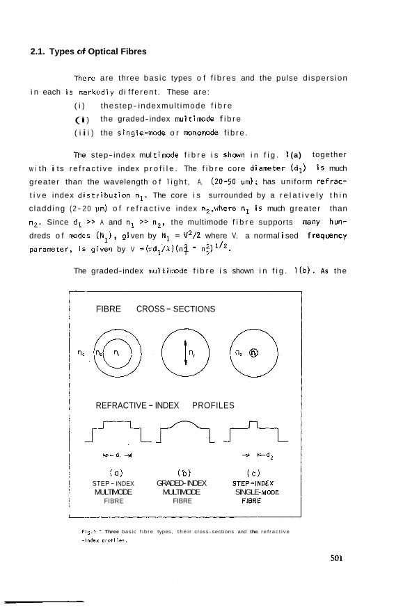
2.1. Types of Optical Fibres
There are three bas ic types o f f i b r e s and the pulse d ispers ion
i n each i s markedly d i f f e ren t . These are:
( i ) thes tep- indexmul t imode f i b r e
(i i ) the graded-index mul timode f i b r e
( i i i ) the single-mode o r monomode f i b r e .
The step- index mul timode f i b r e i s shown i n f i g . I (a) together
w i t h i ts r e f r a c t i v e index p r o f i l e . The f i b r e core diameter ( d l ) i s much
greater than the wavelength o f 1 i gh t , A, (20-50 has uni form re f rac -
t i v e index d i s t r i b u t i o n nl. The core i s surrounded by a r e l a t i v e l y t h i n
c ladd ing ( 2- 2 0 um) o f r e f r a c t i v e index n2,where nl i s much greater than
n2. Since dl >> A and nl 7> n2, the multimode f i b r e supports many hun-
dreds o f mdes (N1) , gi ven by N1 = v2/2 where V, a normal i sed f requency
parameter, i s given by V =(ndl/ l)(n2 1 - ni)1'2.
The graded-index multimode f i b r e i s shown i n f i g . l ( b ) . As the
FIBRE CROSS - SECTIONS
REFRACTIVE - INDEX PROFILES
a ) ( b ) ( c ) STEP - INDEX GRADED- INDEX STEP-INDEX MULTIMODE MULTIMODE SINGLE- MODE
FIBRE FIBRE FIBRE
Fig.1 - Three bas ic f i b r e types, t h e i r cross-sections and the r e f r a c t i v e
- index p r o f i l e s .
name impl ies, the r e f r a c t i v e index p r o f i l e o f the core i s graded i .e. i t
decreases r a d i a l l y from the cent re o f the f i b r e ax i s as
where a i s the core radius, A i s the r e l a t i v e r e f r a c t i v e index d i f f e r e n -
ce given by n2 = n l (1 - A), and a i s an exponent which r i ses t o i n f i n i -
t y f o r a conventional step- index mul timode f i b r e . For a value o f a - 2,
the number o f guided modes ( ~ 2 ) i n a graded-index f i b r e i s on ly h a l f the
modes i n a step- index f i b r e wi t h the s a m values o f A and core diameter.
The single-mode f i b r e shown i n f i g . l ( c ) , has core diameter
(d2) comparable t o h and n i i s j u s t g reater than n2. The f i b r e supports
on ly one s p a t i a l propagation rnode and f o r t h i s cond i t i on a t a p a r t i c u l a r
h, we must have V < 2.405; as before V i r given by (nd2/l)(n: - n f ) l 12 .
2.2. Mechanisms Contributing to Pulse Dispersion
A sho r t o p t i c a l pulse broadens a f t e r propagation i n an o p t i c a l
f i b r e due t o the fo l l ow ing mechanisms:
(a) Internoda2 dispersion ( r ) i s caused by the d i f ferences i n 9
the group v e l o c i t i e s o f the var ious mdes propagating i n the f i b r e . Va-
r ious o ther terms have a l so been used t o r e f e r t o intermodal dtspersion,
such as moda1 dispersion, waveguide dispers ion, mul t i - p a t h d i s p e r s ion,
multimode d ispers ion and mnochromatic d ispers ion. T i s completely do- 9
minant i n a multimode stap-index f i b r e as Nl i s large, and the o ther d is -
pers ive mechanisms, as discussed below, can be neglected. By designing a
graded-index f i b r e , N2 = (1/2) NI, and hence r can be reduced d r a s t i - 9
c a l l y ; i t i s e l im inated completely i n a single-mode f i b r e as N1 = 1. The
discussion and masuremrnt o f r i n multimode f i b r e s i s the s u b j e c t o f 9
t h i s paper.
(b) IntrwdaZ dZspersion (T,) i s due t o the wavelength depen-
dente o f the f i b r e core r e f r a c t i v e index, causing ve loc i t y d i f f e r e n c e s
amng the spect ra l components o f the 1 i ght source used. Two o ther terms
have a l so been used t o r e f e r t o r n a m l y , mater ia l d ispers ion and chro- m 7 rnatic d ispers ion. r i s n e g l i g i b l e compared t o r i n step- index multimo-
m 9
de f i b r e s even i f a l i g h t e m i t t i n g diode (LED) w i t h 40nm spect ra l width,
i s used as the 1 i gh t source. W i t h opt imal l y designed graded-index mul t i -
m d e f i b r e s T can be - l nsec/km and hence w i t h LED exc i t a t i on , T,,, can g
be greater than .r f o r A < 1 pm, as shown by ~awsonl'. Further .rm i s a 9
s t rong func t ion o f A, vary ing inverse ly and r can be zero i n the region m
o f 1.3 pm.
(c) Mode Dispersion (.r ) o f a p a r t i c u l a r propagating mode m
caused by the frequency dependence o f the propagating constant of t h a t
mode. As the magnitude o f .rm i s very small, i t w i l l on l y be important i n
single-mode f ib res operated near the zero mater ia l d ispers ion region.
(d) ProfiZe Kspersion (.r ) i s caused by the v a r i a t ion, wi t h P
wavelength, o f the r e l a t l v e re f rac t i ve- index d i f f e rence between core and
cladding. T w i l l be important on ly i n graded-index f i b res , a t a given P
wavelength, so tha t T can be minimised. We have prev ious ly shown8> l1 9
tha t r was n e g l i g i b l e compared t o .r w i t h measurements c a r r i e d o u t a t P 9
three wavelsngths, (694, 782, 871 nrn) bu t the resu l t s cannot be genera-
l ised: the r e l a t i v e r e f r a c t i v e index d i f f e rence between core and c lad-
d ing as a func t ion of wavelength can be markedly d i f f e r e n t as many d i f -
fe ren t materiais have been used f o r the core o f o p t i c a l f i b res .
2.3. Intermodal Dispersion in Multimode Fibres: Rays and Modes
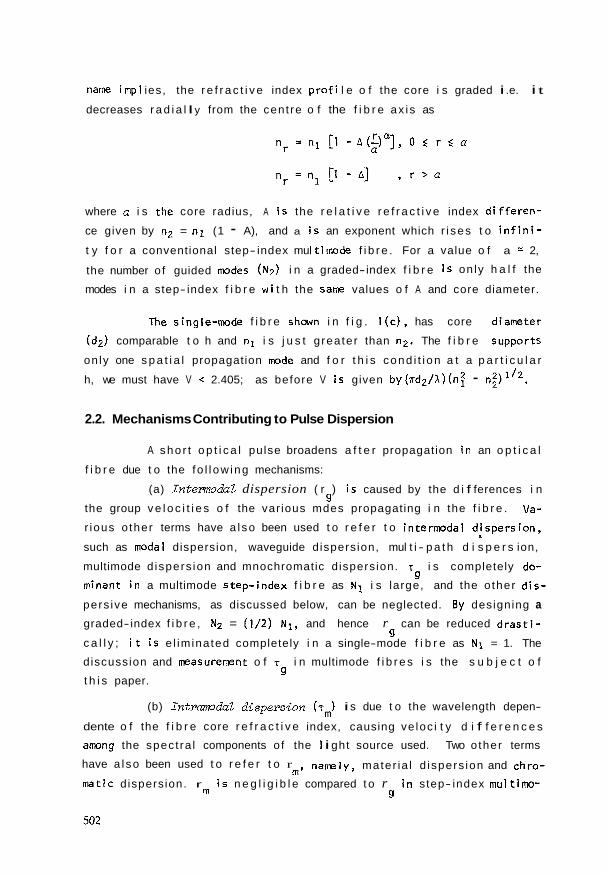
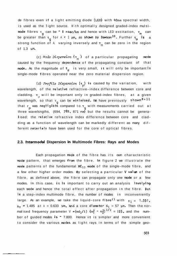
Each propagation mde o f the f i b r e has i t s own c h a r a c t e r i s t i c
mode pat tern, t h a t emerges from the f i b r e . I n f i g u r e 2 we i l l u s t r a t e the
mode pat te rns o f the fundamental HEli mode o f the single-mode f i b r e , and
a few o ther h igher order modes. By s e l e c t i n g a p a r t i c u l a r V value o f the
f i b r e , as def ined above, the f i b r e can propagate on ly one mode o r a few
modes. In t h i s case, i t i s important t o car ry out an ana lys is i nvo l y ing
each mode and hence the t o t a l e f f e c t a f t e r propagation i n the f i b r e . But
i n a step- index multimode f i b r e , the number o f modes i n inconvenient ly
large. As an example, we take the l i qu id- co re f i b r e l 1 w i t h n l = 1 2 5 1 ,
ng 1.485 a t A = 0.633 pm, and a core diameter dl = 57 pm. Then the nor-
mal ised frequency parameter V =(sdl/h) (nf - n;) 'I2 = 125, and the num-
ber o f guided modes i s - 7.800. Hence i t i s s impler and more convenient
t o consider the var ious modes as l i g h t rays i n terms o f the simple geo-
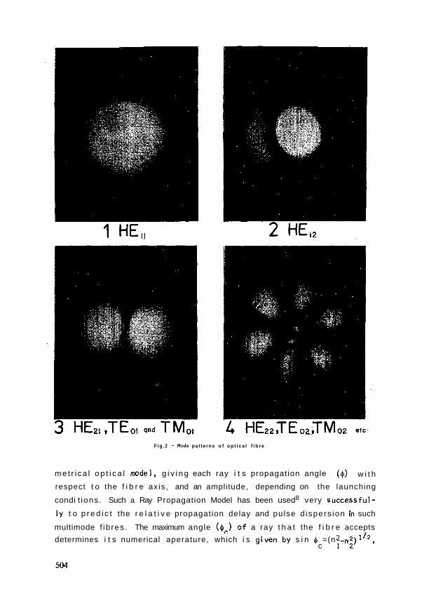
F i g . 2 - Mode p a t t e r n s o f o p t i c a l f i b r e
met r i ca l o p t i c a l model, g i v i n g each ray i t s propagation angle ($1 w i t h
respect t o the f i b r e axis, and an amplitude, depending on the launching
condi t ions . Such a Ray Propagation Model has been used8 very successful-
l y t o p r e d i c t the r e l a t i v e propagation delay and pulse d ispers ion in such
multimode f ib res . The maximum angle ($c) o f a ray t h a t the f i b r e accepts
determines i t s numerical aperature, which i s given by s i n 4 =(n2 lI2, c P 2 )
FIBRE- --- AXIS
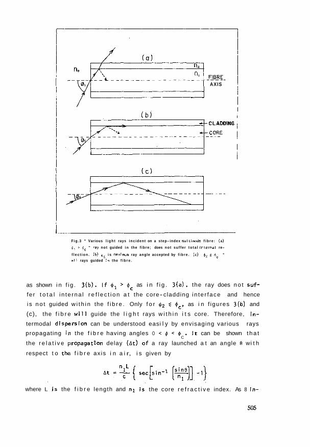
F i g . 3 - Various l i g h t rays i n c i d e n t on a s tep- index muitimode f i b r e : (a)
41 > $c - ray n o t guided i n the f i b r e ; does n o t s u f f e r t o t a l i n t e r n a l re-
f l e c t i o n . (b) (c i s maximum ray angle accepted by f i b r e . (c) (2 5 (c - a i 1 rays guided i 9 the f i b r e .
as shown i n f i g . 3(b) . I f > @c as i n f i g . 3(a) , the ray does n o t su f -
fe r t o t a l i n te rna l r e f l e c t i o n a t the core- cladding i n te r face and hence
i s n o t guided w i t h i n the f i b r e . Only f o r @2 @,, as i n f igures 3(b) and
(c), the f i b r e w i l l guide the l i g h t rays w i t h i n i t s core. Therefore, i n -
termodal d ispers ion can be understood easi l y by envisaging various rays
propagating i n the f i b r e having angles O < $I < $ . It can be shown t h a t C
the r e l a t i v e propagation delay ( ~ t ) o f a ray launched a t an angle 8 wi t h
respect t o thé! f i b r e ax is i n a i r, i s given by
where L i s the f i b r e length and n l i s the core r e f r a c t i v e index. As 8 i n -
creases, so does A t and i f a shor t 1 i g h t pulse i s launched i n t o a1 1 the
rays which can propagate a t d i f f e r e n t angles i n the core, the output pu l-
se w i l l be broadened. Intermodal d ispers ion i s completely d o m i n a n t i n
step- index mul timode f i bres and i s o f the order o f 30 ns/ km f o r every
per cent o f i n d e x d i f f e r e n c e between c o r e a n d c ladding. I n a g r a d e d -
index mul timode f i bre, T can be reduced considerably on ly i f launching i s 9
c a r r i e d ou t co r rec t l y , by matching the launching spot- size t o the cha-
r a c t e r i s t i c spot-size o f the f i b r e ; w i t h mismatched l a u n c h i n g c o n d i - t ions12, T becomes large, comparable t o t ha t obtained wi t h step- index
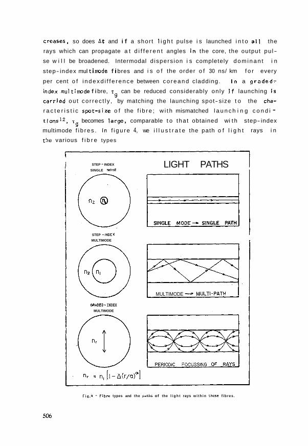
9 multimode f i b r e s . In f i g u r e 4, we i l l u s t r a t e the path o f l i g h t rays i n
the various f i b r e types
STEP - INDEX
SINGLE MODE
STEP -1NDEX
MULTIMODE
GRADED- INDEX MULTIMODE
LIGHT PATHS
SINGLE MODE- SINGLE PATH 1
MULTIMODE - MULTI-PATH
Fig .4 - F i b r e types and the paths of the l i g h t rays w i t h i n these f i b r e s .
3. A NANOSECOND TEST FACILITY
The problem o f measuring intermodal pulse d ispers ion i n a mul-
timode f i b r e f a l l s i n t o these categor ies, ( i ) t o se lec t a s u i t a b l e op-
t i c a l o s c i l l a t o r which produces o p t i c a l pulses, ( i i ) t o launch the l i g h t
e f f i c i e n t l y i n t o the f i b re , ( i i i ) t o de tec t the o p t i c a l p u l s e s , t h a t
emerge frorn the f ib re ,w i t h a photodetector, o r other s u i t a b l e system,
( i v ) t o d i sp lay the input and output pulses t o the f i b r e and t o record
these f o r measurement and i n t e r p r e t a t i o n o f intermodal d ispers ion.
To observe a c lea r broadening, the response o f the measuring
system has t o be much smal ler than the intermodal d ispers ion o f the f i -
bre. To malte the measurement system f a i r l y v e r s a t i l e , i t should be able
t o measure intermodal d ispers ions o f - 1 ns, which would be observed i n
long lengths o f graded-index f i b r e s and sho r t lenghts o f step- index f i -
bres. Hence the combined response o f the input o p t i c a l pulse, the photo-
de tec tor arid the osc i 1 Ioscope has t o be much less than one nanosecond, i . e. each o f these components has t o have a response o f the order o f a few
hundred p i coseconds .
3.1. Production of Subnanosecond Optical Pulses
We used a semlconductor laser as the source o f the o p t i c a l
pulses f o r the f o l lowing reasons: ( i ) l a rge pulse peak powers can be ea-
s i l y obtained, ( i i ) the output wavelength o f semiconductor lasers can be
var ied between 0 . 8 pm and 1.5 um by s u i t a b l e choice o f the materia1s;and
t h i s i s the region of i n t e r e s t i n o p t i c a l f i b res s ince they have minimum
at tenuat ion and minimum d ispers ion wi t h i n t h i s region, ( i i i ) semiconduc-
t o r lasers can be e a s i l y modulated t o produce o p t i c a l pulses having du-
ra t i onso f a few hundred picoseconds, ( i v ) systems w i l l use these devices
due t o t he i r compactness and easy modulation; hence measurement i n the
laboratory w i t h semiconductor devi ces determines the charac ter is t i c s o f
the f i b r e accurately, as would be encountered i n f i e l d condi t ions. This
i s p a r t i c u l a r l y important s ince the output s p a t i a l c h a r a c t e r i s t i cs o f se-
miconductor lasers are completely d i f f e r e n t t o o ther gas o r s o l i d - s t a t e
lasers, e.g. He-Ne and ruby lasers, which a l so have been used f o r d isper -
s ion measuri~ments?
5 OHM
MICROSTRIP TRANSMISSION
TRIGGER , I nF
so OHM ? I 2 N 3 9 0 4
AVALANCHE TRANSISTOR
$ 4,7 OHM
LASER sG-2001 \ L ~ ~ ~ , .
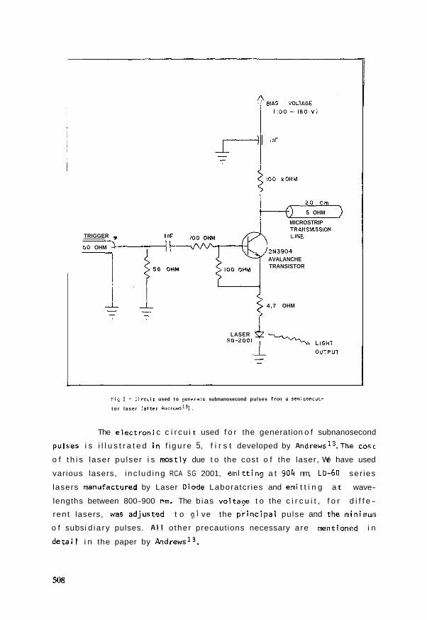
F i s . 5 - C i r c u i t used t o Zenerate subnanosecond pulses from õ seniiconduc-
t o r laser ( a f t e r ~ n d r e w s ' ~ ) .
The e lec t ron i c c i r c u i t used f o r the generation o f subnanosecond
pulses i s i l l u s t r a t e d i n f i g u r e 5, f i r s t developed by ~ n d r e w s l ~ . ~ h e cosc
o f t h i s laser pu lser i s mostly due t o the cost o f the laser, We have used
various lasers, i nc lud ing RCA S G 2001, e rn i t t ing a t 904 nm, L b 6 0 ser ies
lasers manlifactured by Laser Diode Laboratcr ies and erni t t i n g a t wave-
lengths between 800-900 nm. The b ias vol tage t o the c i r c u i t , f o r d i f f e -
rent lasers, was adjusted t o g i ve the p r i n c i p a i pulse and the rninirnum
o f subsi d ia ry pulses. A1 1 o ther precautions necessary are mentioned i n
d e t a i l i n the paper by ~ n d r e w s l ~ .

3.2. Launching and Deoection Optics
The launching and detec t ion o p t i cs have t o be desigiied care-
f u l l y bear ing i n mind tha t the semiconductor laser emi t s i n the near I n -
f rared. This i s f a i r l y irnportant f o r measurements t o be done rap fd l y and
w i t h ease. With a v i s i b l e cw laser , such as the He-Ne laser,measurernents
can be ca r r i ed out eaç i l y d i t h o u t any specia! o p t i c a l components.
I n f igure 6(a) i s the scherriatic arrangernent o f the launchlng
arrangemen t and the photograph, f i g u r e 6 (b) , s h w the components used.
Since the laser (L) emits i i g h t w i t h a la rge divergente angle, microscope
ob jec t i ve Ell, m g n i f i c a t i o n x45 w i t h a n u w r i c a l aperature o f 0.65, i s
used t o c o i l e c t a l l tne l i g h t and co i l ima te i t i n t o a p a r a l l e l beam.This
para1 l e l beam passes through a te t rava r i n t e r m d i a t e uni t (T), which hou-
ses a beam-sp l i t te r (B.s.). The l i g h t i s focussed i n t o the f i b r e by mi-
croscope ob jec t i ve MZ, which can be changed t o vary the Iaunch numerical
aperature. The f i b r e i s he?d i n p o s i t i o n by a vacuum chuck14 ( V . C . ) . To
.the te t rava r intermediate u n i t i s attached an i l l u m i n a t o r ( I ) , an i n c l i -
ned nonocular eye-piece uni t (M.T.) and a microscope i n f r a r e d v i e w e r , ( I .V) manufactured by Electrophysics Corporation. This a r rangemen t i s
necessary ( i ) t o pos i t í on the laser a t the foca l po in t o f microscope ob-
j e c t i v e M1 end i s clone by r o t a t i n g the beam-spl i t ter t o p o s i t i o n P2 and
viewing through the i n f r a r e d viewer; ( i i ) t o focus the l i g h t i n t o the f i -
bre. This i s done by r o t a t i n g the beam-spl i t ter t o p o s i t i o n P1. The f i -
bre end i s placed a t the foca l po in t o f the microscope ob jec t i ve M2, and
then i s f u r t h e r adjusted so tha t the Fresnel r e f l e c t i o n o f the laser spot
from the f i bre end can be observed, again through the i n f r a r e d viewer.Fi-
ne adjustment of the f i bre posi t i o n enables the l ase r focussed spot t o
be pos i t ioned i n the middle o f the f i b r e core.
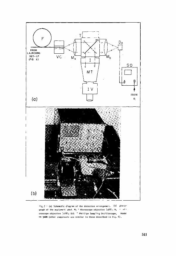
l'he l i g h t emerging frm the f i b r e end i s observed w i t h a de-
t e c t i o n arraiigernent, exac t l y s imi l a r t o the launching arrangement, and
shown i n f i g . 7. Focussing o f the output l i g h t i n t o the photodetector
( D ~ ) i s done simi l a r l y by observing the Fresnel r e f l e c t i o n from the de-
tec to r . Microscope o b j e c t i v e M3 (x20, N.A. = 0.54) has a numerical ape-
ra tu re greater than t h a t o f the f i b r e t o capture a11 the l i g h t rays emer-
ging from the f i b r e . Microscope ob jec t i ve M4 has a magni f i ca t ion o f x10
and ensures tha t the focussed spot diameter i s less than the diarneter o f

Fig.6 - (a ) Schematic diagram o f the iaunching arrangemnt. (b) Photograph
of the equipmnt used. L - semiconductor laser; Hi - microscope ob jec t i -
ve (x45); Hn - microscope object ive (x10) o r o ther coupling lens; Hj - coupling lens; D1 - s i l i c o n avalanche photodetector; T - Eaiing Tetravar
lntermediate Unit; B.S. - beam-split ter; P1, P2 - two posi t ions of the
beamspl l t t e r ; I - I l iuminator uni t; H.T. - i nc l i ned k n o c u l a r eye-piece
uni t ; I.V. - microscope in f ra red viewer; F - f i b r e under test; H.P - mi-
cro-posi t ioners; V.C. - vacuum chuck.
FROM .AUNCHING
SET- CIP
(FIG 6)
+ F R O M
D,
Fig.7 - (a) Schemtic diagram o f the detection arrangement. (b) photo-
~ r a p h of the equipment used. Hg - Hicroscope object ive ( ~ 2 0 ) ; M!, - mi-
croscope object ive ( ~ 1 0 ) ; S.O. - Phi l l i p s Sampl ing Oscl lloscope, Hodel
PH 3400 (other c q o n e n t s are simi lar t o those descrlbed i n f i g . 6).
t h e a c t i v e area o f the pho tode tec to r . I f t h l s i s n o t done, the d i s p e r -
s i o n measured w i ? l be less than i t s t r u e va lue, caused b y e l i m i n a t i n g
l i g h t which t r a v e l l e d a t t h e h i g h e r angles; i n o t h e r words, f i l t e r i n g o f
h i gher o r d e r modes.
3.3. Detectian and Display of Output Pulses
The requ i rements o f t h e pho tode tec to r a r e ( i ) h i g h s e r s i t i v i t y
so t h a t l a r g e actenuat ior is i n t h e f i b r e can be t o l e r a t e d and hence nea-
surements i n long lengths a r e p o s s i b l e , ( i i ) h i g h t i m e r e s o l u t i o n s o
t h a t even sinal 1 magnitudes of d i s p e r s i o n niay be detected, s p e c i a l l y i n
iong l e ~ g t i - i s o f graded- index f i b r e . P r e s e n t l y s i l i c o n avalanche diodes
f u l f i ! l t h i s r e q ~ i r e m e n t ve ry aaequate ly and we used v a r i o u s types manu-
f a c t u r e d by EMI, RCA and o t h e r companies. A1 1 had response o f l e s s than
a few hundred picoseconds and were v e r y adequate f o r o u r measurements.
Recently, an u l t ra- h igh- speed photodiode, Mode! 403 B, manufactured by
Spectra-Physics, has b e c o m ava i l a b l e , and has a r i s e - and f a l l - t i m e o f
-50 psec. A l though i t i s n o t o f t h e avalanche type, i t can s t i 11 be used
f o r d i s p e r s i o n measure,mnts as f i b r o l o s s can be ex t reme ly l o w ( < l dB/km)
and hence the i n p u t pu lse wouldnoc s u f f e r much a t t e n u a t i o n .
The d i s p l a y o f the pu lses has t o be done on sampl ing o s c i l l o s -
cope as r e a l - t i m e o s c i l l o s c o p e s donot have the speed necessary. We have
used a P h i l l i p s Sampling Osc i l l oscope , Model PM 3400, h a v i n g a r i s e - t i m e
o f 200 ps. I f a much f a s t e r response i s r e q u i r e d , a T e k t r o n i x Sam-
p l i n g Osci 1 loscope wi t h 25 psec r i s e t i m e can be used, c o n s i s t i n g o f 7904
mainframe, two 751 1 Sampl i n g Uni t s , 7 T l l Sampl i n g Sweep and two S-4 Sam-
p l i n g heads. Permanent records o f the observed pu lses can be made e i t h e r
by photographing the pu lses f rom the o s c i l l o s c o p e o r feed ing a s u i t a b l e
o u t p u t f rom i t t o an X- Y recorder .
3.4. Procedure for Measuring Dispersion and Results Obtained
The f i b r e s ends a r e f i r s t prepared, t o have a m i r r o r f i n i s h ,
by us ing a f i b r e b r e a k i n g machine c o n s t r u c t e d on t h e p r i n c i p l e s f i r s t
r e p o r t e d by Gloge et aZ. l5 The m i r r o r f i n i s h i s checked b y o b s e r v i n g
t h e ends wi t h a microscope. Th is i s impor tan t t o achieve a h i g h laun-

c h i n g e f f ic iemcy and t o launch a c c u r a t e l y wi t h a knowri numer ica l apera-
t u r e . The f i b r e ends a r e then p laced i n the vacuum chucks and h e l d f i rm-
l y i n pos i t i o n . Thé l a s e r L i s swi tched on and wi t h the beam-spl i t t e r o f
f i g . 6 i n t h e p o s i t i o n P p , i t i s p laced a t the f o c a l p o i n t o f o b j e c t i v e
M1. The beam-spi i t t e r i s then r o t a t e d t o pos i t i o n P 1 and the 1 i g h t f o -
cussed o n t o c le tector D l w i t h a c o u p l i n g lens M3. The o u t p u t f rom t h e de- \
t e c t o r i s f e d t o the sampl i n g o s c i l l oscope . By observ ing t h e t r a c e on
the osc i l losc;ope, the i n p u t p r o f i l e i s o p t i m i s e d b y a d j u s t i n g t h e supp ly
v01 tage t o t t ie i a s e r p u l s e r . F ig . 8(a) shows one example o f the r e s u l t
ob ta ined . The 1 i g h t i s launched i n t o the f i b r e by observ ing the Fresnel
~ i ~ . 8 - An example of the resul ts obtained wi th the Nanosecond Test Fa-
c i l i t y : (a) Input pulse launched i n t o f i b r e . (b) Output pulse a f t e r 105
m of Teiebrás f i b r e 79. Internwdal pulse disperslon i s 1.7 nsec, a f t e r deconvolution o f input pulse.

r e f l e c t i o r f rom the end o f the f i b r e , as a l ready d i s c u s s e d i n s e c t i o n
3.2. The o e t p u t frorn d e t e c t o r D 2 i s a l s o fed t o the sampl i n g o s c i I losco-
pe. I n f i g . 8(b) i s t h e o u t p u t pu lse observed a f t e r p ropaga t ion i n 105 m
o f Telebrás f i b r e 79. A f t e r deconvo lu t ion o f the i n p u t pu lse w i d t h , t h e
in termodal d i s p e r s i o n i s 1.7 nsec.
4. DISCUSSION AND CONCLUSION
The Nanosecond Tes t F a c i l i t y desc r ibed above p rov ides a sirn-
p l e , q u i c k and e f f e c t i v e m a n s f o r measuring in termodal d i s p e r s i o n i n
mul t imode o p t i c a l f i b r e waveguides. We have a l s o d iscussed the v a r i o u s
mechanisms t h a t cause d i s p e r s i o n and the r e l a t i v e magnitude of each i n
va r ious types o f f i b r e s . Measurement o f d i s p e r s i o n i n t h e f i b r e i t s e l f
i s impor tan t t o determine the i n f o r m a t i o n c a r r y i n g c a p a c i t y o f t h e f i -
b re . We have used t h e F a c i l i t y t o c a r r y o u t a sys temat i c s tudy6 o f d i s -
p e r s i o n i n TELEBRAS f i b r e s . I n p a r t i c u l a r , we i n v e s t i gated whether t h e
Ray Propagat ion Model c o u l d be used t o p r e d i c t the d i s p e r s i o n and t h e
l e n g t h dependence o f d i s p e r s i o n . The l a t t e r i s o f utrnost irnportance t o
i n v e s t i g a t e mode rn ix ing e f f e c t s and t h e i r I n f luence on d i spers ion ; these
r e s u l t s a re t o be pub l ished s h o r t l y 1 6 .
We a re very g r a t e f u l t o ~ e i e c o m u n i c a ~ õ e s B r a s i l e i r a s S/A (TE-
LEBRAS) f o r i i n a n c i a l l y s u p p o r t i n g t h i s work and f o r s u p p l y i n g t h e f i - b res . One o f us íJ.5.M. Ayres Neto) thanks FAPESP f o r a post- graduate
s c h o l a r s h i p . We a l s o thank D r . F.M. Smolka f o r des ign ing and s u p p l y i n g
the vacuum chuck.
REFERENCES
1 . H.M. M. Graciosa, "Cornun icações Opt icas : Um Programa ~ r a s i l e i ro", Re-
v i s t a ~ e l e b r á s , Ano I I , no 4 , 3-7, Outubro-Dezembro 1978.
2. K.C. Kao, " Fibras b t i c a s : h i s t ó r i a e f u t u r o" , Rev is ta Nacional de
~elecornunicaçÕes, Ano 1 , n? 2, 25-27, Junho 1979.
3. R.D. Maurer, " Fibras o t i c a s e componentes", Rev is ta Nacional de Te-
lecomunicaçÓes, Ano 1, n? 2, 27-31, Junho 1979.
4. "A ação dcecisiva da Telebrãs", e "Aqui nasce a tecnologia" , Rev is ta
Nacional de ~elecomunicaçÕes, Ano 1, n? 4, 62-67, Agosto 1979.
5. H.R.D. Sunak and João B a t i s t a de M. Ayres Neto, "Medidas do c o e f i c i - e n t e de conversão de modos em f i b r a s Ó t i c a s multimodo" , Rev is ta B r a s i -
l e i r a de F í s i c a , 9 (1 ) , 205-216, Março 1979.
6. João B a t i s t a de M. Ayres Neto, " E f e i t o s de propagação em f i b r a s Õ t i -
cas rnultimodo", Tese de Mestrado, I n s t i t u t o de F í s i c a , Un ive rs idade Es-
tadua l de Campinas, Campinas 13.100, Sept. 1979.
7. H.R.D. Suriak and João B a t i s t a de M. Ayres Neto, " Mate r ia l d i s p e r s i o n
mesurements i n o p t i c a l f i b r e waveguides", Rev is ta B r a s i l e i r a de F í s i c a ,
( t h i s i s s u e ) , 10 (3 ) , 000-000, Sept.1980.
8. H.R.D. Sunak, "Experimental Study o f p u l s e d i s p e r s i o n i n mult imode
o p t i c a l f i b r e waveguides", Ph.D. Thesis , U n i v e r s i t y o f Southampton, Sou-
thampton, U.K. 1975.
9. P.W.Smith, "Mode-locking o f l a s e r s " Proc. Inst.Elect.Electron.Eng. , 58 (9 ) , 1342-1357, September 1970.
10. R.Dawson, "Pulse w iden ing i n a mult imode o p t i c a l f i b ' re e x c i t e d by a
pu lsed GaAs LED", Appl i e d Opt i cs, 13 (2) , 264-265, February 1974.
11. H.R.D. Sunak, "The wavelength dependence o f pu lse d i s p e r s i o n i n m u l -
t imode o p t i c a l f i b r e waveguides", Rev is ta B r a s i l e i r a de F i s i c a , ( t h i s
issue) , 10(3) , 000-000, Sept. 1980.
12. H.R.D. Sunek, "Pulse d i s p e r s i o n measurements i n conven t iona l S e l f o c
f i b res" , App l ied Opt i cs , 1 8 ( 7 ) , 1106-1109, A p r i l 1979.
13. J.R. Andrews, " lnexpensive l a s e r d iode p u l s e genera to r f o r o p t i c a l
waveguide s tud ies" , Review o f S c i e n t i f i c Instruoaents, 45 ( I ) , 22-24, Ja-
nuary 1974.
14. A.H. Cherin, A. Osborne, and D.M. Petrowski , "Vacuum-assisted s i 1 i -
con- chip rnu l t i F i b r e chuck", Appl i e d Opt i cs , 26 ( 6 ) , 1464-1465, June,1977.
15. D. Gloge, P.W. Srnith, D.L. B isbee and E.L. Chinnock, "Opt i ca l f i b r e
end p repara t io r i f o r low- loss s p l i c e s l ' , B e l l System Technica l Journal, 52
(91, 1579-1588. Novernber 1973.
16. H.R.D. Sunak and J.B.M. Ayres Neto, "The l e n g t h dependence o f I n t e r -
moda1 p u l s e d i ~ ~ p e r s i o n i n Telebrás Mult imode O p t i c a l f i b r e waveguides I',
t o be pub 1 i shed.