gl400 series gl622/gl612 gl400 series …...the grade laser is an easy-to-use tool that offers...
TRANSCRIPT

GL400 Series
www.trimble.com
Trimble Construction Division5475 Kellenburger RoadDayton, Ohio 45424USA
+1-937-245-5600 Phone
www.trimble.com
User GuideBedienungsanleitung
Manuel de l´utilisateurGuida per l´uso
Gúia del usuarioGebruikershandleiding
OperatörshandbokBrugermanual
Guia do UsuárioBruksanvisningKäyttäjän opas
取扱説明書
© 2007, Trimble Navigation Limited. All rights reserved.
GL622/GL612GL400 Series
www.trimble.com
Trimble Construction Division5475 Kellenburger RoadDayton, Ohio 45424USA
+1-937-245-5600 Phone
www.trimble.com
User GuideBedienungsanleitung
Manuel de l´utilisateurGuida per l´uso
Gúia del usuarioGebruikershandleiding
OperatörshandbokBrugermanual
Guia do UsuárioBruksanvisningKäyttäjän opas
取扱説明書
© 2007, Trimble Navigation Limited. All rights reserved.
Руководство пользователя
Russ_Titel.indd 1 06.05.2008 08:38:53
© 2012 , Trimble Navigation Limited. All rights reserved.PN Q104848 Rev. D(05/13)
Trimble Spectra Precision Division5475 Kellenburger RoadDayton, Ohio 45424-1099, USA
+1-937-245-5600 Phone
Instrukcja obsługiGL622/GL612
130533trimble_GL622_00_Um.indd 1 22.05.13 09:22

Printed in Germany Q104848 Rev. D(05/13)
Service and Customer Advice
North & Latin AmericaTrimble Spectra Precision Division8261 State Route 235Dayton, Ohio 45424U.S.A.+1 (888) 272-2433(Toll Free in U.S.A.)+1-937-482-0030 Faxwww.trimble.comwww.spectraprecision.comwww.spectra-productivity.com
Africa & Middle EastTrimble Export Middle-EastP.O. Box 17760JAFZ View, DubaiUAE+971-4-881-3005 Phone+971-4-881-3007 Fax
EuropeTrimble Kaiserslautern GmbHAm Sportplatz 567661 KaiserslauternGERMANY+49-6301-711414 Phone+49-6301-32213 Fax
Asia-PacificTrimble Navigation Singapore PTE Ltd.80 Marine Parade Road, #22-06Parkway ParadeSingapore, 449269+65 6348 2212 Phone+65 6348 2232 Fax
ChinaTrimble BeijingRoom 2805-07, Tengda Plaza,No. 168 Xiwai StreetHaidian DistrictBeijing, China 100044+86 10 8857 7575 Phone+86 10 8857 7161 Faxwww.trimble.com.cn
d f
hg
i
k
i
c
e
b
a
j
l
Service and Customer Advice
North & Latin AmericaTrimble Spectra Precision Division5475 Kellenburger RoadDayton, Ohio 45424-1099, USA+1-937-245-5600 Phonewww.trimble.comwww.spectraprecision.comwww.spectra-productivity.com
Africa & Middle EastTrimble Export Middle-EastP.O. Box 17760JAFZ View, DubaiUAE+971-4-881-3005 Phone+971-4-881-3007 Fax
EuropeTrimble Kaiserslautern GmbHAm Sportplatz 567661 KaiserslauternGERMANY+49-6301-711414 Phone+49-6301-32213 Fax
Asia-Pacifi cTrimble Navigation Singapore PTE Ltd.80 Marine Parade Road, #22-06Parkway ParadeSingapore, 449269+65 6348 2212 Phone+65 6348 2232 Fax
ChinaTrimble BeijingRoom 2805-07, Tengda Plaza,No. 168 Xiwai StreetHaidian DistrictBeijing, China 100044+86 10 8857 7575 Phone+86 10 8857 7161 Faxwww.trimble.com.cn
130533trimble_GL622_00_Um.indd 2 22.05.13 09:22

1
TABLE OF CONTENTS
Introduction 2FOR YOUR SAFETY 2COMPONENTS 2How to use the Laser System 3 Powering the Laser 3 RC602 Radio Remote Control 3 Turning On/Off the RC602 3LASER SETUP 4 Turning On/Off the Laser 4 Features and functions 4 Standard Features 5 X-Y-grade entering mode 5 Using the Rotation mode 6 Manual mode 6 Special MENU Features 7 Menu Functions (Radio controlled) 7 Automatic PlaneLok mode 8 Automatic Grade Match 9 Automatic Axis Alignment (only GL622) 10 Activating/Deactivating Standby mode 10 Start Reference Check 10 Setting Menu 10 Info 11 Service menu 11Special Features - Vertical Setup 12 Line Scan 12 Setting menu details 12 Pairing 12 Pairing the transmitter with remote control 13 Pairing the transmitter with receiver 13 Mask mode 13 Grade Entry 14 Grade Display 14 Sensitivity 14 HI-alert selection 14 User Name 15 Set Password 15 Password On/Off 15 Radio (RF-Channel) 15 Select Language 16CALIBRATION 16 Checking Calibration of the Y- and X-Axes 16 Checking Calibration of the Z-(vertical) Axis 16Troubleshooting 17PROTECTING THE UNIT 18CLEANING AND MAINTENANCE 18PROTECTING THE ENVIRONMENT 18WARRANTY 18TECHNICAL DATA 19ELECTROMAGNETICAL COMPATIBILITY 20
GB
130533trimble_GL622_00_Buch 1 29.05.13 07:15

2
IntroductionThank you for choosing one of the Spectra Precision Lasers from the Trimble family of precision lasers.The grade laser is an easy-to-use tool that offers accurate horizontal, vertical and sloped laser reference up to 1300 ft (400 m) away using a receiver.
For Your Safety
For hazardless and safe operation, read all the user guide instructions.
• Useofthisproductbypeopleotherthanthosetrainedonthisproductmayresultinexposuretohazardouslaser light.
• Donotremovewarninglabelsfromtheunit.• TheGL622/GL612isaclass2laser(<3,4mW)IEC60825-1:2007)• Neverlookintothelaserbeamordirectittotheeyesofotherpeople.• Alwaysoperatetheunitinawaythatpreventsthebeamfromgettingintopeople‘seyes.• Ifinitialserviceisrequired,whichresultsintheremovaloftheouterprotectivecover,removalmustonlybe
performed by factory-trained personnel.Caution:Useofotherthanthedescribeduserandcalibrationtoolsorotherproceduresmayresultinexposuretohazardouslaserlight.
Caution:UsingdifferentthandescribedattheGL6X2userguide,mayresultinunsafeoperation.
COMPONENTS
a Keypad/LCD-Display b Handle c Rotor d Sunshade e Axes-Alignment-Marks f Sighting Guides/Scope Mounts g Battery door h Rubber Cover/Recharge Jack i 5/8” x 11 Tripod Mounts j Rubber Feet k Turnable Legs l Plus and Minus Battery Diagrams
130533trimble_GL622_00_Buch 2 29.05.13 07:15

3
HOW TO USE THE LASER SYSTEM
POWERING THE LASER
BatteriesWARNING
Ni-MHbatteriesmaycontainsmallamountsofharmfulsubstances.Besuretochargethebatterybeforeusingitforthefirsttime,andafternotusingitforanextendedlengthoftime.Chargeonlywithspecifiedchargersaccordingtodevicemanufacturer‘sinstructions.Donotopenthebattery,disposeofinfireorshortcircuit;itmayignite,explode,leakorgethotcausingpersonalinjury.Disposeinaccordance with all applicable federal, state, and local regulations. Keep the battery away from children.Ifswallowed,donotinducevomiting.Seekmedicalattentionimmediately
Recharging the BatteriesThelaserisshippedwitharechargeableNi-MHbatterypack.Note: TheapproximatechargeofthebatteriesisshownatthelefttopsideoftheLCD.
Thechargerrequiresapprox.10hourstochargeemptyrechargeablebatteries.
Forcharging,connecttheplugofthechargertotherechargejackofthebatterypack.
Neworlong-timeout-of-userechargeablebatteriesreachtheirbestperformanceafterbeingchargedandrechargedfivetimes.ForIndoorapplicationsthechargercanbeusedasapowersupplyfortheGL.
Alkalinebatteriescanbeusedasabackup.Insert4D-cellbatteriesnotingtheplus(+) and minus (-) diagrams inside the battery housing.
The batteries should only be charged when the laser is between 50° F and 104° F (10°C to 40°C). Charging at a higher temperature may damage the batteries. Charging at a lower temperature may increase the charge time and decrease the charge capacity, resulting in loss of performance and shortened life expectancy.
RC602 Radio Remote Control
Powering the RC6021. Open the battery door using a coin or similar pry device to release the batterydoortabontheRC602.RC602willbeshippedwithalkalinebatteries Rechargeable batteries can be used optional but need to bechargedexternally
2.InserttwoAAbatteriesnotingtheplus(+)andminus(-)diagramsinside the battery housing.
3.Close the battery door.Pushdownuntil it “clicks” into the lockedposition.
Turning On/Off the Radio Remote ControlThe radio remote control is a hand-held device that allows you to send operational commands to the laser from a remote location.
Pressthepowerbuttontoturnontheradioremotecontrol.A“ ”andadditionalverticalbarsappearintheright corner of the remote’s top display line indicating the radio connection status between the laser and the remote control.
Note:Whentheremotecontrolisinitiallyturnedon,thestandarddisplay(modelnumberandsoftwareversion)appearforthefirst3seconds,thentheaxessymbolsandlast-enteredgradeforeachaxisbrieflyappearintheLCD.
Witheverybuttonpress,theLCDbacklightisactivatedandturnsoffautomaticallyifnobuttonispressedfor8seconds.
To turn off the radio remote control, press and release the power button.
Note:5minutesafterthelastbuttonpress,theremotecontrolturnsoffautomatically.
130533trimble_GL622_00_Buch 3 29.05.13 07:15

4
LASER SETUPPosition the laser horizontally (tripod mount and rubber feet downward!) on a stable platform, wall mount or tripod at the desired elevation.The laser recognizes automatically whether it is used horizontally or vertically when switched on.
Turning On/Off the laserPressthepowerbuttontoturnOn/Offthelaser.
Note:Dependingonthesetup(horizontalorvertical)andifagradevaluehasbeendialedin,theunitstartsthetemperature/referencecheckwhilethethermometersymbolisflashing.
Whenthetemperature/referencecheckhasbeenfinished,thestandarddisplayappearsandthebubblesymbolsflash until self-leveling has been completed.
Iftheself-levelingcan’tbefinishedbasedontheselectedsensitivity,anerrormessageappears.
Features and Functions
Standard DisplayTheremotecontrolmirrorsthefunctionalityoftheGLkeypad
Button 1: QuicklypressandreleasestartstheMENU entry.
Button 2: Quicklypressandreleasestartsthegrade entering mode.
Button 3: Quicklypressandreleaseactivates/deactivates the manual mode.
Button 4: Quicklypressandreleasetotogglethrough the pre-selected rotation speeds.
Button 5, 8:up/downarrowbuttons.Button 6, 7:left/rightarrowbuttons.Button 9: ON/OFFbutton-pressfor1secondto
turnontheunit;pressandholdfor2seconds to turn off the unit.
Leveling/Standby – LED (green/red)
Batterystatuslaser HIalertfunctionisactivatedMaskselection BatteryStatusRemoteControl
StatusRadioConnectivityRotation speed
130533trimble_GL622_00_Buch 4 29.05.13 07:15

5
Standard Features
X-Y-grade entering – Step and Go mode
Quicklypressandreleasebutton2startsthegradeenteringmode.Bothgradevalueswillbeshown.Press/releasebutton1 a grade reverse YPress/releasebutton2 agradereverseX(onlyGL622)Press/releasebutton3 a return to the standard displayQuicklypressandreleasebutton4 to confirm the selected grade value and return to the standard display
Press and hold button 6 or 7(left/right)tochangeX-axisgradevalue(onlyGL622)afterthecomma;pressand hold buttons 6 + 7simultaneouslystartsX-axisquickchangemodewherethegradevalueinfrontofthecomma will be set to 0% and then starts changing in 1% increments.Press and hold button 5 or 8 (up/down) for changingY -axisgradevalue; pressandholdbuttons5 + 8 simultaneouslystartsY-axisquickchangemodewherethegradevalueinfrontofthecommawillbesetto0% and then starts changing in 1% increments.Note: The speed of the grade value change increases with the amount of time the button is held down.Note: Thegradevalueforbothaxesincreasesin1.00%increments.Whenthegradevalueforeitheraxisreachesitshighestamount,thegradevalueswitchestothelowestvalueforthataxis.Forexample,thevalueswitchesfrom+25%to-25%.Thelaserwillself-leveltotherequiredgradepositionafterconfirmingthegradechangewithbutton4.Note:Thebubblesymbolsatthelaser’sLCDwillflashuntilthelaserhasbeenself-leveledtotherequestedgrade position.
X-Y-grade entering – Digit Select mode (Default)
Quicklypressandreleasebutton2 starts the grade entering mode. .Bothgradevalueswillbeshown.Press/releasebutton1 aquicksetto0%Press/releasebutton2 a change the sign in front of the grade valuePress/releasebutton3 a return to the standard display.Quicklypressandreleasebutton4 to confirm the selected grade value and return to the standard display.
Press and release button 5 or 8(downorup)tomovethecursortotheX-(onlyGL622)orY-axisPressing and releasing button 6 or 7(rightorleft)movesthecursortotheright/left.
130533trimble_GL622_00_Buch 5 29.05.13 07:15

6
Usebutton 1 or 2(PlusorMinus)tosetthedesireddigit.Thelaserwillself-leveltotherequiredgradepositionafterconfirmingthegradechangewithbutton4.
Note: Thebubblesymbolsatthelaser’sLCDwillflashuntilthelaserhasbeenself-leveledtotherequestedgrade position.
Using the Rotation modeRepeatedly pressing the button 4togglesthrough300,600,900rpmregardlessiftheunitisinautomatic or manual mode.
Manual modePressing and releasing button 3attheStandardDisplayactivates/deactivatesthe manual mode regardless if set up horizontal or vertical.Manualmodeisindicatedbyhorizontallinesnexttotheaxessymbols.
InManualmode(horizontal),theY-axiscanbeslopedbypressingtheUp-(5)andDown-Arrow-(8) buttons on thelaser‘skeypadortheremotecontrol.Additionally,theX-axiscanbeslopedbypressingtheLeft-(6) and Right-(7)Arrow-buttonsonthelaserorremotecontrol.Inverticalmode,theupanddownarrowbuttonsadjusttheZ-axisslope,andtheleftandrightarrowbuttonsalignthelaserbeamtotheright/leftside.To resume automatic self-leveling mode, press the manual button again.
Special MENU Features
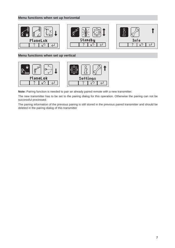
Menu Functions (Radio controlled)Press and release button 1attheStandardDisplaytoentertheMENU.The menu offers always only the features which can be selected depending on the setup (horizontal or vertical).The icon of the selected function will be highlighted.Adownarrowat the the right site indicates that the user can scroll down through themenuusing the button 8 (down arrow).Aftergoingtothenextmenurow,anup/downarrowatthetherightsiteindicatesthattheusercanscrollup/down through the menu (4 different screens) using the buttons 5/8(up/downarrows).Pressing and releasing button 3 changes the unit always back to the standard or previous display.Press and release the buttons 6/7 until the desired icon at the selected menu row is highlighted.Press and release button 4 to open the submenu OR start the selected function.
130533trimble_GL622_00_Buch 6 29.05.13 07:15
7
Menu functions when set up horizontal
Menu functions when set up vertical
Note: Pairing function is needed to pair an already paired remote with a new transmitter.The new transmitter has to be set to the pairing dialog for this operation. Otherwise the pairing can not be successful processed. The pairing information of the previous pairing is still stored in the previous paired transmitter and should be deleted in the pairing dialog of this transmitter
130533trimble_GL622_00_Buch 7 29.05.13 07:15

8
Automatic PlaneLok modeThe PlaneLok mode can be activated in horizontal and vertical automatic and manual mode. InPlaneLokmodewhensetuphorizontal,thebeamwillbelockedtoafixedelevationpoint(upto80m(260ft)locatedononeaxisat each side of the laser. Forkeepingverticalalignmentsfixedtoadirectionpoint,PlaneLokcanbeusedinbothdirectionsontheX-axis.1. Set up the laser over the reference point.2.AttachtheHL750receivertoagraderod.PlacethereceiveratthesecondpointandadjustittotheOn-gradeposition.Thereceivershouldbepermanentlymountedatthis location and at the desired elevation.
3.Usethesightingguidesonthetopofthelasertoalignthelasertothereceiver.Turnthelaseronthetripoduntilitisroughlyalignedtothereceiver’sposition(thealignmentrangeforbothaxesis+/-40°).
4.PressandreleasetheMENUbuttonattheStandardDisplayandselectPlaneLok.Inverticalmode,PlaneLokcanbestartedimmediatelybypressingbutton4.
Horizontalsetup Vertical setup
5.Whensetuphorizontally,pressandreleasebutton4 to open the PlaneLok submenu; select the desired PlaneLokaxis(X-onlyGL622)thenpressbutton4 to start PlaneLok.
Note:Thelaserstartstosearchforthereceiver.AflashingReceiverandLocksymbolappearsattheselectedaxisandbecomessolidwhenPlaneLokhasbeencompleted.
Note:Whenusedinverticalmode,thereceiverhastobeplacedwith the photocell on the bottom side.TheHL750display shows a flashing –PL– during the time thelaserissearchingandadjustingthebeamtotheon-gradeposition.WhenPlaneLok is complete, –PL– stops flashingat theHL750display. Note:Thelasercontinuestoservotothereceiver’ssignals.6.ExitingofPlaneLokcanbedonebypressingbutton3(ESC).
mm
130533trimble_GL622_00_Buch 8 29.05.13 07:15

9
Automatic Grade MatchTheGradeMatchmodecanbeactivatedinhorizontalautomaticandmanual mode.InGradeMatchmode,thelasercanbeusedtomeasuretheexistinggradevaluebetweentwoknownelevationpoints(upto80m(260ft)locatedononeaxisateachsideofthelaser1. Set up the laser over the reference point.
2.AttachtheHL750receivertoagraderod.Checkthelaser’selevationnexttothelaserthenpositionthereceiveratthesecondpointWITHOUTchangingthereceiver’selevationontherod.
3.Usethesightingguidesonthetopofthelasertoalignthelasertothereceiver.Turnthelaseronthetripoduntilitisroughlyalignedtothereceiver’sposition(thealignmentrangeforbothaxesis+/-40°).
4.PressandreleasetheMENUbuttonattheStandardDisplayandselectGradeMatch.
5.SelectthedesiredGradeMatchaxis(X-onlyGL622)thenpressbutton 4tostartGradeMatch.
Note:Thelaserstartstosearchforthereceiver.AflashingReceiverandanglesymbolappearsat theselectedaxisanddisappearswhenGradeMatchhasbeen completed.Whilethelaserissearchingandadjustingthebeamtotheon-gradeposition,theHL750displayshowsaflashing–GM–.WhenGradeMatchhasbeencompleted,theHL750goesbacktothestandardelevation display. The remote control as well as the laser will display the final measured grade value.Note:IfGradematchcan’tbecompletedbycheckingthelimits,thelasercomeswithanErrormessage(GradeMatchhasFailed)whichcanbedeletedwithbutton4(OK).TheHL750goesback to standard elevation indication.
mm
130533trimble_GL622_00_Buch 9 29.05.13 07:15

10
Automatic Axis Alignment (only GL622) AutomaticAxisAlignmentmode adjusts automatically the directionthegradeaxisispointingtothereceiver’slocationbyanelectronicallysimulationofrotatingtheunitonitsbasetomatchthehub.UsingAxisAlignment,thelaseraxiscanbealignedtoonedirectionhub(upto80m(260ft)locatedononeaxisateachsideofthelaser.1. Set up the laser over the reference point.2.PlacethegraderodwiththeattachedHL750receiveratthedesired
direction hub. 3.Usethesightingguidesonthetopofthelasertoalignthelasertothereceiver.Turnthelaseronthetripoduntilitisroughlyalignedtothereceiver’sposition(thealignmentrangeforbothaxesis+/-40°).
4.PressandreleasetheMENUbuttonattheStandardDisplayandselectAxisAlign.5.Selectthedesiredaxisthenpressbutton4tostartAxisAlign.
Note:Adjusting the receiver into thebeambeforestarting theautomaticAxisAlignment reduces the timeneeded for finishing the alignment.
Activating/Deactivating Standby modePressandreleasetheMENUbuttonattheStandardDisplayandselectStandby.Pressing and releasing button 4 activates the Standby mode. Theself-levelingwillbestoppedandthebeamwillbeturnedoffwhiletheHIalertisstillactive.ThedisplayshowsthestandbysymbolandtheLevel/StandbyLEDflashesredevery5seconds.
To deactivate Standby mode and restore full operation of the laser, press and release button 4.
Start Reference Check Beforestartingsomegradeworkwhich is verysensitiveanadditionalReferenceCheckcanbestartedmanually.PressandreleasetheMENUbuttonat theStandardDisplayandselectReferenceCheck.Pressing and releasing button 4startstheReferenceCheckconsideringthecurrenttemperatureinsidethehousing.Whiletherotorchecksthecorrectpositiontherotationwillbestopped.
Setting MenuPressandreleasetheMENUbuttonattheStandardDisplayandselectSettings.Press and release button 4toopentheSettingMenu;selectthedesiredfunctionthenpressbutton4 to open the selected submenu function OR start the selected function. PleaseseetheSettingMenudetailsattheendoftheuserguide.
130533trimble_GL622_00_Buch 10 29.05.13 07:15
11
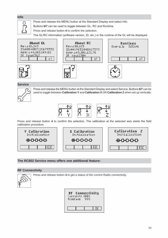
InfoPressandreleasetheMENUbuttonattheStandardDisplayandselectInfo.Buttons6/7canbeusedtotogglebetweenGL,RCandRuntime.Press and release button 4 to confirm the selection. TheGL/RCinformation(softwareversion,ID,etc.)ortheruntimeoftheGLwillbedisplayed.
ServicePressandreleasetheMENUbuttonattheStandardDisplayandselectService.Buttons6/7 can be used to toggle between Calibration Y and Calibration X OR Calibration Z when set up vertically.
Press and release button 4 to confirm the selection.The calibration at the selected axis starts the fieldcalibration procedure.
The RC602 Service menu offers one additional feature:
RF ConnectivityPress and release button 4 to get a status of the current Radio connectivity.
130533trimble_GL622_00_Buch 11 29.05.13 07:15
12
Special Features - Vertical Setup
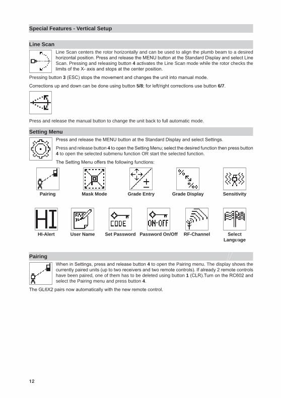
Line ScanLine Scan centers the rotor horizontally and can be used to align the plumb beam to a desired horizontalposition.PressandreleasetheMENUbuttonattheStandardDisplayandselectLineScan. Pressing and releasing button 4 activates the Line Scan mode while the rotor checks the limitsoftheX-axisandstopsatthecenterposition.
Pressing button 3(ESC)stopsthemovementandchangestheunitintomanualmode.
Correctionsupanddowncanbedoneusingbutton5/8;forleft/rightcorrectionsusebutton6/7.
Press and release the manual button to change the unit back to full automatic mode.
Setting MenuPressandreleasetheMENUbuttonattheStandardDisplayandselectSettings.
Press and release button 4toopentheSettingMenu;selectthedesiredfunctionthenpressbutton4 to open the selected submenu function OR start the selected function.
TheSettingMenuoffersthefollowingfunctions:
Pairing Mask Mode Grade Entry Grade Display Sensitivity
HI-Alert User Name Set Password Password On/Off RF-Channel
Select Language
PairingWheninSettings,pressandreleasebutton4 to open the Pairing menu. The display shows the currentlypairedunits(uptotworeceiversandtworemotecontrols).Ifalready2remotecontrolshave been paired, one of them has to be deleted using button 1(CLR).TurnontheRC602andselect the Pairing menu and press button 4.
TheGL6X2pairsnowautomaticallywiththenewremotecontrol.
130533trimble_GL622_00_Buch 12 29.05.13 07:15

13
Pairing the transmitter with remote controlThe chain symbol at button 1 indicates the remote has never been paired before which means no radio connectivity is given. Pressing the pairing button 1willinitiateapairingrequest.Thetransmitterhastobeinpairing mode as shown above.
Note:Makesurethatpairingmodeisselectedonlyatonetransmitterwhichiswithintheradiorangeoftheremoteduringapairingrequest.Otherwisepairingprocedurecanbeconfused.
Pairing the transmitter with receiverTo pair the transmitter and the receiver select Settings and press and release button 4 to open the Pairing menu.Thedisplayshowsthecurrentlypairedunits(upto2receivers).Ifalready2receivershavebeenpaired,one or both of them have to be deleted using button 1(CLR).
A
BC
Next,turnonthereceiverthenpressandholdtheDeadband(A)andtheAudio(B)buttonsfortwoseconds.AftertwosecondsthedisplayshowsMENUfirst,thenRDIO.
PressandreleasetheUnits(C)button–displayshowsthecurrentradiomode.
IfnotalreadysettoLS,pressUnitsbuttonandthenpressDeadbandorAudiobuttonuntilLS is displayed. PressUnitsbuttonagaintoenterselection.PressandreleasetheAudiobutton–displayshowsPAIR.PresstheUnitsbuttonagain–thedisplayshowsPAIRandarotatingbar.AftercompletingPAIR,OKwillbedisplayed.TheGL6X2pairsnowautomaticallywiththenewreceiver.PressandreleasethePowerbuttontwotimestoexitthemenu.Alasersymbolislittoconfirmthereceivercancommunicatewiththelaser.
Mask modeSelecttheMaskiconandpressandreleasebutton4toopentheMasksettingmenu.Dependingonwhichsideorcornerthebeamshouldbeturnedoff,therequiredsectorcanbeselected.Pressand release the buttons 5 to 8 for moving a short flashing line around the mask mode symbol. For selecting the sector where the bar is flashing, press and release button 1(SET).Aftersettingthefirst sector, button 1changestoshowCLRwhichofferesthecapabilityofdeletingtheselectedmask
sectoragain.Usebutton5 to 8tomovetheflashingbartootherrequiredareasandrepeatthesettingprocess.Whenallareashavebeenset,pressbutton 4 to store the mask sector selection until the unit will be turned off.
Hinweis:Theunitalwayspowersupwiththemaskmodedeactivated(default).
130533trimble_GL622_00_Buch 13 29.05.13 07:15

14
Grade Entry SelecttheGradeEntryiconandpressandreleasebutton4toopentheGradeEntrymenu.
Buttons6/7canbeusedtotogglebetweenStepandGoandDigitSelect.
Press and release button 4 to confirm the selection.
Step and Go Digit Select
Grade DisplaySelecttheGradeDisplayiconandpressandreleasebutton4toopentheGradeDisplaymenu.
ThedesiredGradeDisplayMode(Percent/Permille/Degree)canbeselectedusingthebuttons6/7.
Press and release button 4 to confirm the selected display mode.
Sensitivity SelectionSelect the Sensitivity icon and press and release button 4 to open the Sensitivity menu. The desiredSensitivity:Low,Mid(Default)andHigh)canbeselectedusingthebuttons6/7. Press and release button 4 to confirm the selected Sensitivity.
HI-alert SelectionSelecttheHIiconandpressandreleasebutton 4toopentheHI-alertmenu.ThedesiredHI-alert:5min.(Default),30secondsandHI-Off)canbeselectedusingthebuttons 6/7. Press and release button 4toconfirmtheselectedHI-alert.
130533trimble_GL622_00_Buch 14 29.05.13 07:15
15
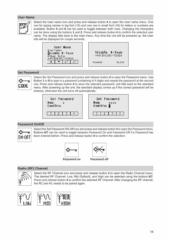
User NameSelecttheUsernameiconandpressandreleasebutton4toopentheUsernamemenu.Onerowfortypingnamesinbigfont(15)andonerowinsmallfont(18)forlettersornumbersareavailable.Button5 and 8canbeusedtotogglebetweenbothrows.Changingthecharacterscan be done using the buttons 1 and 2. Press and release button 4 to confirm the selected user name.Thedisplayfallsbacktothemainmenu.Anytimetheunitwillbepoweredup,theUserinfo will be displayed for couple seconds.
Set PasswordSelect the Set Password icon and press and release button 4toopenthePasswordmenu.UseButton1 to 8 to type in a password containing of 4 digits and repeat the password at the second row. Press and release button 4 to store the selected password; unit falls back to the standard menu.Afterpoweringuptheunit,thestandarddisplaycomesupifthecorrectpasswordwillbeentered, otherwise the unit turns off automatically.
Password On/OffSelecttheSetPasswordON-Officonandpressandreleasebutton4 to open the Password menu. Buttons6/7 can be used to toggle between Password On and Password Off if a Password has been entered before. Press and release button 4 to confirm the selection.
Password on Password off
Radio (RF) Channel SelecttheRFChanneliconandpressandreleasebutton4toopentheRadioChannelmenu.ThedesiredRFChannel:Low,Mid(Default),andHighcanbeselectedusingthebuttons6/7. Press and release button 4toconfirmtheselectedRFChannel.AfterchangingtheRFchannel,theRCandHLneedstobepairedagain.
130533trimble_GL622_00_Buch 15 29.05.13 07:15

16
Select LanguageSelect the Language icon and press and release button 4toopentheLanguagemenu.Usebutton5 to 8toselecttherequiredlocallanguage(EN,DE,IT,FR,ES,PT,NL,DA,NO,SV,FI,PL,TR,CZ).Press and release button 4 to store the selected Language; unit falls back to the standard menu.
CALIBRATION
Checking Calibration of the Y- and X-Axes1. Set up the laser 30 m (100 ft) from a wall and allow it to level.2. Setthegradeto0.000%inbothaxes.3. Raise/lowerthereceiveruntilyougetanon-gradereadingforthe+Yaxis.Using
the on-grade marking notch as a reference, make a mark on the wall.
Note: Forincreasedprecision,usethefine-sensitivitysetting(1.5mm/1/16in.)onthe receiver.
4.Rotatethelaser180°(-Yaxistowardthewall)andallowthelasertore-level.5.Raise/lowerthereceiveruntilyougetanon-gradereadingforthe–Y/axis.Usingthe
on-grade marking notch as a reference, make a mark on the wall. 6.Measurethedifferencebetweenthetwomarks.Iftheydiffermorethan3mmat30m(1/8inchat100feet),thelaserneedscalibrating.
7.AftercheckingtheY-axis,rotatethelaser90°.Repeattheabovestartingwiththe+Xaxisfacingthewall.
Checking Calibration of the Z-(vertical) AxisTo check vertical calibration, you need a plumb bob with at least 10m (30ft) of string.1. Suspend the plumb bob in front of a house i.e., attached to a window frame whose window height is at least
10m (30ft). 2.Setupthelaserinverticalsothatthelaserbeamstrikesthereceiver’son-gradepositionatthetopofthestring.3.Lookforanydeviationusingthereceiverfromthetopofthestringtothebottomofit.Ifthedeviationismorethan1mm(<1/16in.),theverticalaxisneedscalibrating.
Note:Ifcalibrationisrequired,please,refertothecalibrationinstructionsonourTrimblewebsitewww.trimble.com/support.shtml.
130533trimble_GL622_00_Buch 16 29.05.13 07:15

17
TroubleshootingAnyerrormessagecanbedeletedwithashortpressofbutton4 (OK). The table shows the related description andpossiblesolutions.Thenextservicecentershouldbecontactedifadifferenterrormessageasshownatthe table will be displayed.
Error codes Description Solution
21 TemporaryEEpromproblem Repeat pairing and re-enter the customer settings
120 HIalert-UnitHeigtchanged ChecklaserbeamelevationafterdeletingtheHIalert
130 MechanicalLimitduringAxisAlignment,GradeMatchorSpotMatch
Re-align the closer to the alignmentpoint;checkifexistingslopeisabove+/-25%
131 RakeAngleLimit Re-align the unit closer to the alignment point
140 Laser beam blocked Makesuretherearenoobstacles between the transmitterandtheHL750
141 Time Out - Function could not be completed in the allowed time
Checkradiooperatingrange/connection; check stable laser setup
150 Noreceiver-Receivernotavailableforsingleaxisautomatic function
Makesurethereceiverisonandpaired
152 Noreceiver-Thelasersearchedfor the receiver but could not find it
Checktheoperatingrangeforauto function and restart the auto alignment
153 Lost Receiver - The laser searched and found the receiver but then lost it
Checktheoperatingrangeforauto function and restart the auto alignment
160 XorYlevelsensordefect Contactservicecenter
130533trimble_GL622_00_Buch 17 29.05.13 07:15

18
PROTECTING THE UNIT
Donotexposetheunittoextremetemperaturesortemperaturechanges(donotleaveinsidethecar).Theunitisveryrobustandcanresistdamageifdroppedevenfromtripodheight.Beforecontinuingyourwork,alwayscheckthelevelingaccuracy.SeeCheckingCalibrationsection.Thelaseriswaterproofandcanbeused indoors and outdoors.
CLEANING AND MAINTENANCE
Dirtandwaterontheglasspartsoflaserorprismwillinfluencebeamqualityandoperatingrangeconsiderably.Cleanwithcottonswabs.Removedirtonthehousingwithalint-free,warm,wetandsmoothcloth.Donotuseharshcleansersorsolvents.Allowtheunittoairdryaftercleaningit.
PROTECTING THE ENVIRONMENT
The unit, accessories and packaging ought to be recycled. This manual is made of non-chlorine recycling paper.Allplasticpartsaremarkedforrecyclingaccordingtomaterialtype.
Do not throw used batteries into the garbage, water or fire. Remove them in compliance with environmental requirements.Hinweis für Kunden in der EU
Notice to Our European Union Customers
Forproductrecyclinginstructionsandmoreinformation,pleasegoto:
www.trimble.com/environment/summary.html
RecyclinginEurope:TorecycleTrimbleWEEE, Call+31497532430,andaskforthe“WEEEAssociate”
or
Mailarequestforrecyclinginstructionsto:TrimbleEuropeBVc/oMenloWorldwideLogisticsMeerheide455521DZEersel,NL
Warranty
TrimblewarrantstheGL622/GL612tobefreeofdefectsinmaterialandworkmanshipforaperiodof5years.Trimble or its authorized service center will repair or replace, at its option, any defective part, or the entire product,forwhichnoticehasbeengivenduringthewarrantyperiod.Ifrequired,travelandperdiemexpensestoandfromtheplacewhererepairsaremadewillbechargedtothecustomerattheprevailingrates.Customersshould send theproduct toTrimbleNavigationLtd. or thenearest authorized service center forwarrantyrepairsorexchange,freightprepaid.Anyevidenceofnegligent,abnormaluse,accident,oranyattempttorepair the product by other than factory-authorized personnel using Trimble certified or recommended parts, automatically voids the warranty. Special precautions have been taken to ensure the calibration of the laser; however,calibration isnotcoveredby thiswarranty.Maintenanceof thecalibration is theresponsibilityoftheuser.TheforegoingstatestheentireliabilityofTrimbleregardingthepurchaseanduseofitsequipment.Trimblewillnotbeheldresponsibleforanyconsequentiallossordamageofanykind.Thiswarrantyisinlieuofallotherwarranties,exceptassetforthabove,includinganyimpliedwarrantymerchantabilityoffitnessfora particular purpose, are hereby disclaimed. Thiswarrantyisinlieuofallotherwarranties,expressedorimplied.
130533trimble_GL622_00_Buch 18 29.05.13 07:15

19
TECHNICAL DATA
GL622/GL612
Leveling accuracy1,3: ±0.5mm/10m,1/16“@100ft,10arcsecondsGradeaccuracy1,3: ±1.0mm/10m,1/8“@100ft,20arcsecondsRotation: 300,600,900rpmOperational area1,2: appr.400m(1300feet)radiuswithdetectorLasertype: reddiodelaser650nmLaserclass: class2,<3.2mWSelf-levelingrange: appr.±14°Graderange(Y,X-GL622): ±25%bothaxes(notsimultaneously)Levelingindicators: LCDindicationsandLEDflashesRadiorange(HL750): upto80m(260ft)Powersource: NiMHbatterypackBatterylife1: 35hoursNiMH;40hoursalkalineOperatingtemp.: -20°Cto50°C(-4°Fto122°F)Storagetemp.: -20°Cto70°C(-4°Fto158°F)Tripodattachments: 5/8x11horizontallyandverticallyDustandWaterproof: IP67Weight: 3.1kg(6.8lbs)Lowvoltageindication: LCDbatteryindicatorLowvoltagedisconnection: unitshutsoff
1) at 21°Celsius2) under optimal atmospheric circumstances3) along the axis
Remote Control RC602
Radio Operating range1,3: upto100m(330ft)Powersource: 2x1.5VAAalkalinebatteriesBatterylife1: 130hoursDustandWaterproof: IP66Weight: 0.26kg(0.4lbs)
DECLARATION OF CONFORMITY
Please disregard the declaration of conformity within the manual.
Followingisthevaliddeclaration:
We
Trimble Kaiserslautern GmbH
Declareunderoursoleresponsibilitythattheproducts
GL622/GL612 and RC602
Towhichthisdeclarationrelatesisinconformitywiththefollowingstandards:
EN 50371:2002, EN 60825-1:2007, ETSI EN 300328 V1.7.1:2006, ETSI EN 301489-1 V1.9.2:2011, ETSI EN 301489-3 V1.4.1:2002
following the provisions of directive R&TTE 1999/5/EC.
The managing director
130533trimble_GL622_00_Buch 19 29.05.13 07:15

20
ELECTRO-MAGNETIC COMPATIBILITY
Compliancestatement(part15.19)Thisdevicecomplieswithpart15oftheFCCRulesandIndustryCanadalicence-exemptRSSstandard(s).Operationissubjecttothefollowingtwoconditions:(1)thisdevicemaynotcauseharmfulinterference,and(2)thisdevicemustacceptanyinterferencereceived,includinginterferencethatmaycauseundesiredoperation.Warning(part15.21)Changesormodificationsnotexpresslyapprovedbythepartyresponsibleforcompliancecouldvoidtheuser’sauthoritytooperatetheequipment.ThisinparticularisapplicablefortheantennawhichhasbeendeliveredwiththeGL622/GL612 andRC602UnderIndustryCanadaregulations,thisradiotransmittermayonlyoperateusinganantennaofatypeandmaximum(orlesser)gainapprovedforthetransmitterbyIndustryCanada.Toreducepotentialradiointerferencetootherusers,theantennatypeanditsgainshouldbesochosenthattheequivalentisotropically radiated power (e.i.r.p.) is not more than that necessary for succesful communication.
130533trimble_GL622_00_Buch 20 29.05.13 07:15