dispensette s dispensette s organic - brand.de · instruções de segurança 4 funções e...
TRANSCRIPT

Dispenset te ® S Organ icDispenset te ® S
Manua l de Operação · 3 Opera t ing Manua l · 33

2

Po
rtu
gu
ês
3
Índice
Página
Instruções de Segurança 4
Funções e Limitações de uso 5
Tabela de Seleção de Dispensadores 8
Elementos de Operação 9
Primeiros Passos 10
Montagem 10
Purga 12
Dispensação 13
Acessórios 14
Limites de Erro (Volume Nominal, Volume Parcial) 16
Verificação de Volume (Calibração) 17
Ajuste 18
Limpeza 19
Substituição do tubo de dosificação/válvulas 21
Autoclavação 23
Informações para Pedido · Acessórios · Peças de Substituição 24
Resolução de problemas 29
Reparo · Endereços de contato 30
Serviço de Calibração 31
Informações de Garantia · Descarte 32

4
Eventualmente, este instrumento pode ser utilizado com materiais, operações e equipamentos perigosos. Está além do escopo deste manual abordar todos os riscos de segurança potenciais associados com seu uso nestas aplicações. É responsabilidade do usuário do instrumento consultar e estabelecer práticas de segurança e saúde, além de determinar a aplicabilidade de limitações legais antes da utilização.
Instruções de segurança
1. Todos os usuários devem ler e compreender este manual de operação antes de utili-zar o instrumento além de observar estas instruções durante o uso.
2. Siga as instruções gerais para prevenção de acidentes e instruções de segurança; ex.: usar roupas protetoras, óculos de proteção e luvas.
3. Observe as informações do fabricante dos reagentes utilizados.
4. Ao dispensar líquidos inflamáveis, evite a formação de carga estática, ex. não dispense em recipientes plásticos; não seque os instrumentos com pano seco.
5. Use o instrumento somente para dispensar líquidos, com especial atenção às limitações de uso e operação. Observe as operações não recomendadas (veja página.4.) Em caso de dúvida, contate o fabricante ou fornece-dor.
6. Sempre utilize o instrumento de forma que nem o usuário e nem outras pessoas estejam em risco. Ao dispensar, o tubo de dosificação deve sempre apontar para longe de você ou de qualquer outra pessoa. Evite respingos e derramamentos. Utilize somente recipientes apropriados.
7. Nunca pressione o pistão para baixo quando a tampa de proteção do tubo de dosificação estiver rosqueada.
8. Nunca remova o tubo de dosificação ou a válvula de recirculação quando o cilindro estiver cheio.
9. Reagentes podem acumular na tampa rosca de segurança do tubo de dosificação. Limpe regularmente.
10. Ao utilizar frascos pequenos, use um suporte de fixação para prevenir o tombamento.
11. O instrumento, montado em um frasco, nun-ca deve ser segurado pelo seu corpo (carca-ça). A quebra ou separação do instrumento e do frasco podem levar a ferimentos ou lesões por produtos químicos (veja pág. 11 Fig.6).
12. Nunca use força sobre o instrumento. Faça movimentos suaves para operar o pistão para cima e para baixo.
13. Somente use peças de reposição originais. Não tente realizar nenhuma alteração téc-nica. Não desmonte o instrumento além do descrito no manual de operações!
14. Sempre verifique o instrumento quanto a defeitos visíveis. Em caso de sinais de pro-blemas potenciais (ex. dificuldade em mover o pistão, válvulas travadas ou vazamento), imediatamente pare a titulação. Consulte a seção “Resolução de Problemas” neste manual (veja pág. 29), e contate o fabricante caso necessário.
Por favor leia com atenção as informações a seguir!!
Funções e Limitações de Uso
Com os dispensadores para frascos Dispensette® S e Dispensette® S Organic os líquidos podem ser dis-pensados diretamente dos frascos. Disponíveis nos modelos digital, analógico e fixo.Os instrumentos tem marcação DE-M conforme e, opcionalmente, equipados com válvula de recirculação.

X
X
X
XX
X
X
X
X
Po
rtu
gu
ês
5
Funções e Limitações de Uso
Quando o instrumento é corretamente utilizado, o líquido dosificado somente entra em contato com os seguintes materiais quimicamente resistentes:
Dispensette® SVidro Borossilicato, Al2O3-cerâmica, ETFE, FEP, PFA, PTFE, platina-irídio, PP (tampa de segurança).Dispensette® S OrganicVidro Borossilicato, Al2O3-cerâmica, ETFE, FEP, PFA, PTFE, tântalo, PP (tampa de segurança)
Em alternativa, é possível utilizar adaptadores de frascos ETFE/PTFE ("Acessórios", página 26). A adequação dos adaptadores de frascos ETFE/PTFE deve ser cuidadosamente verificada pelo próprio utiliza-dor.
Digital Analógico
Dispensette® S Organic (código de cor amarelo)
Digital Analógico Volume Fixo
Dispensette® S (código de cor vermelho)
( código de coramarelo)
( código de cor vermelho)
Volume Fixo
Para a dosificação de ácido fluo- rídrico, recomendamos o dispen-sador para frascos Dispensette®
S Trace Analysis com mola da vál-vula de platina-irídio (veja manual de operação em separado).
Observação:

6
Funções e Limitações de Uso
O instrumento foi desenvolvido para dispensar lí-quidos, observando as seguintes limitações físicas:
– Temperatura de ambos, instrumento e solução, de 15 °C a 40 °C (de 59 °F a 104 °F).
– Pressão de vapor até 600mbar. Aspire lenta-mente acima de 300mbar, para evitar a ebulição do líquido.
– Viscosidade cinemática até 500 mm2/s (viscosi-dade dinâmica [mPas]= viscosidade cinemática [mm2/s] x densidade [g/cm3])
– Densidade: 2.2 g/cm3
Limitações de Uso Limitações de Operação
Líquidos que formam depósitos podem dificultar o movimento do pistão ou causar travamento (ex. soluções que cristalizam ou soluções alcalinas concentradas). Se o pistão apresentar dificuldade de movimentação, o instrumento deve ser limpo imediatamente (página 19).Ao dispensar meios inflamáveis, ex. não dispense em recipientes plásticos, não limpe com lenços secos.
O dosificador Dispensette® foi desenvolvido para aplicações gerais de laboratório e está em confor-midade com os padrões relevantes, ex. DIN EN ISO 8655. A compatibilidade do instrumento com aplicações específicas (ex. análise de traços, uso no setor alimentício, etc.) deve ser verificada pelo usuário. Aprovações para aplicações específicas, ex. para produção e fornecimento de alimentos, fármacos ou cosméticos não estão disponíveis.
Nunca utilize Dispensette® S para
– Líquidos que atacam Al2O3, ETFE, PFA, FEP, PTFE (ex. sódio azida dissolvido).
– Líquidos que atacam vidro borossilicato (ex. ácido fluorídrico)
– Líquidos que são decompostos cataliticamente pela platina-irídio (ex. H2O2)
– Ácido clorídrico >20% e ácido nítrico >30%
– Tetrahidrofurano
– Ácido trifluoroacético
– Líquidos explosivos (ex. dissulfeto de carbono)
– Suspensões (ex. Carvão) pois partículas sólidas podem aderir ou danificar o instrumento.
– Líquidos que atacam o PP (tampa rosca)**
Operações não recomendadas
Nunca utilize Dispensette® S Organic para
– Líquidos que atacam Al2O3, tântalo, ETFE, PFA, FEP, PTFE (ex. sódio azida dissolvido*).
– Líquidos que atacam vidro borossilicato (ex. ácido fluorídrico)
– Bases e soluções salinas
– Líquidos explosivos (ex. dissulfeto de carbono)
– Suspensões (ex. Carvão) pois partículas sólidas podem aderir ou danificar o instrumento.
– Líquidos que atacam o PP (tampa rosca)**
* Sódio Azida dissolvida é permitida em uma concentração máx. de 0,1%
** Em alternativa, é possível utilizar adaptadores de frascos ETFE/PTFE ("Acessórios", página 26). A adequação dos adaptadores de frascos ETFE/PTFE deve ser cuidadosamente verificada pelo próprio utilizador.

Po
rtu
gu
ês
7
Funções e Limitações de Uso
Armazene o instrumento e acessórios somente em locais com boas condições de limpeza, secos e frescos.Temperatura de armazenagem: de -20 °C a +50 °C (de -4 °F a 122 °F).
Condições de armazenagem
Dispensette® S (código de cor vermelho): sua ampla faixa de aplicação permite a dosificação, a partir de frascos, de reagentes agressivos, inclu-indo ácidos concentrados como H3PO4, H2SO4, bases como NaOH, KOH, soluções salinas, assim como vários solventes orgânicos.
Dispensette® S Organic (código de cor ama-relo): é ideal para dispensar solventes orgânicos, incluindo hidrocarbonetos clorados e fluorados (ex. triclorotrifluoroetano e diclorometano), ácidos con-centrados (ex. HCl e HNO3), ácido trifluoroacético, tetrahidrofurano (THF) e peróxidos.
Faixa de aplicação recomendada
Para ajuda na seleção do dispensador correto, Observe as Operações Não Recomendadas e a “Tabela de seleção de dosificadores” na próxima página.
Para a dosificação de ácido fluorídrico, recomenda-mos o dispensador para frascos Dispensette® S Trace Analysis com mola da válvula de platina-irídio (veja manual de operação em separado).
Observação:

8
Tabela de Seleção de Dispensadores
Para a dosificação de ácido fluorídrico, recomen-damos o dispensador para frascos Dispensette® S Trace Analysis com mola da válvula de platina-irídio (veja manual de operação em separado).
A tabela acima representa testes feitos antes do momento desta publicação. Siga sempre as instruções do manual de operações do instrumento, assim como as especificações de uso dadas pelo fabricante do reagente. Além dos produtos químicos presentes nesta tabela, outros podem ser dosificados, tais como uma variedade de soluções salinas, orgânicas e inorgânicas (p.ex., soluções tampão biológicas), detergentes biológicos e meios para cultura de células. Caso necessite de informações referentes a outros reagentes químicos não presentes nesta lista, contate a BRAND. Esta edição: 0517/13
Medium Disp. S Disp. S Organ
Acetaldeído + +Acetil cloreto +Acetilacetona + +Acetofenona +Acetona + +Acetonitrila + +Ácido acético (glac.), 100% + +Ácido acético, ≤ 96% + +Ácido acrílico + +Ácido adípico +Ácido bórico, ≤ 10% + +Ácido bromídrico +Ácido butírico + +Ácido clorídrico, ≤ 20% + +Ácido clorídrico, 20-37% ** +Ácido cloroacético + +Ácido clorosuflônico +Ácido crômico, ≤ 50% + +Ácido cromosulfúrico +Ácido dicloroacético +Ácido fluoroacético +Ácido fórmico, ≤ 100% +Ácido fosfórico, ≤ 85% + +
Ácido fosfórico, 85% + ácido sulfúrico, 98% 1:1
+ +
Ácido glicólico, ≤ 50% +Ácido hexanóico + +Ácido iodídrico, ≤ 57% ** + +Ácido lático +Ácido monocloroacético + +Ácido nítrico, ≤ 30% + +Ácido nítrico, 30-70% */** +Ácido oleico + +Ácido oxálico +Ácido peracético +Ácido perclórico + +Ácido pirúvico + +Ácido propiônico + +Ácido sulfúrico, ≤ 98% + +Ácido tartárico +Ácido tricloroacético +Ácido trifluoroacético (TFA) +Acrilonitrila + +Álcool alílico + +Álcool amílico (pentanol) + +Álcool benzílico + +Álcool isoamílico + +Alumínio cloreto +Amil cloreto (cloropent) +n-Amil acetato + +Aminoácidos +Amoníaco, ≤ 20% + +Amoníaco, 20-30% +Amônio cloreto +Amônio fluoreto +Amônio sulfato +Anidrido acético +Anilina + +Bário cloreto +Benzaldeído + +
Medium Disp. S Disp. S Organ
Benzeno + +Benzil cloreto + +Benzilamina + +
Benzina (gasolina de petróleo), p. ebul. 70-180 °C
+
Benzoil cloreto + +Bromobenzeno + +Bromonaftaleno + +Butanodiol + +1-Butanol + +n-Butil acetato + +Butil metil éter + +Butilamina + +Cálcio carbonato +Cálcio cloreto +Cálcio hidróxido +Cálcio hipocloreto +Carbono tetracloreto +Ciclohexano +Ciclohexanona + +Ciclopentano +Cloro naftaleno + +Cloroacetaldeído, ≤ 45% + +Cloroacetona + +Clorobenzeno + +Clorobutano + +Clorofórmico +Cobre sulfato +Cresol +Cumeno (isopropilbenzeno) + +Decano + +1-Decanol + +Dibenzil eter + +Diclorobenzeno + +Dicloroetano +Dicloroetileno +Diclorometano +Dietanolamina + +Dietil éter +Dietilamina + +1,2-Dietilbenzeno + +Dietilenoglicol + +Difenil éter + +Dimetil sulfóxido (DMSO) + +Dimetilanilina +Dimetilformamida (DMF) + +1,4-Dioxano +Etanol + +Etanolamina + +Éter de petróleo, p. ebul. 40-70 °C +Etil acetato + +Etil metil cetona + +Etilbenzeno +Etileno cloreto +Fenil etanol + +Fenil hidrazina + +Fenol + +Fluido de cintilação + +Formaldeído, ≤ 40% +Formamida + +
Medium Disp. S Disp. S Organ
Glicerol + +Glicol (etilenoglicol) + +Heptano +Hexano +Hexanol + +Hidrogênio peróxido, ≤ 35% +Isobutanol + +Isooctano +Isopropanol (2-propanol) + +Isopropil éter + +Metanol + +Metil benzoato + +Metil butil éter + +Metil formiato + +Metil propil cetona + +Metileno cloreto +Metoxibenzeno + +Nitrobenzeno + +
Óleo de aquecimento (Diesel), p. ebul. 250-350 °C
+
Óleo Diesel, p. ebul. 250-350 °C +Óleo mineral + +Óleos essenciais +n-Pentano +Percloroetileno +Petróleo, p. ebul. 180-220 °C +Piperidina + +Piridina + +Potássio cloreto +Potássio dicromato +Potássio hidróxido +Potássio permanganato +Prata acetato +Prata nitrato +Propilenoglicol (Propanodiol) + +Salicilaldeído + +Sódio acetato +Sódio cloreto +Sódio dicromato +Sódio fluoreto +Sódio hidróxido, ≤ 30% +Sódio hipoclorito +Tetracloroetileno +Tetrahidrofurano (THF) */ ** +Tetrametilamonio hidróxido +Tolueno +Triclorobenzeno +Tricloroetano +Tricloroetileno +Triclorotrifluoretano +Trietanolamina + +Trietilenoglicol + +Trifluoretano +Turpentina +Uréia +Xileno +Zinco cloreto, ≤ 10% +Zinco sulfato, ≤ 10% +
* use adaptadores para frascos em ETFE/PTFE** use junta em PTFE para bloco de válvulas

Po
rtu
gu
ês
9
Elementos de Operação
Chave de montagemTubo de enchimento e recirculação
Tubo de recirculação
Tubo de enchimento telescópico
Ajuste de volume
Locking
Tampa
Ajuste de volume
Carcaça
Tampa rosca
válvula de recirculação
Capa protetora Cilindro de dispensação
Pistão Pistão
Bloco de válvulas (rosca de frasco GL 45)
Tubo de dosificação
Comando da
Base do pistão
Marcador
Botão
Trava de segurança
Lacre
Unidade suporte do pistão
Trava
Dis
pens
ette
® S
Dig
ital
Dis
pens
ette
® S
A
naló
gico

1
2
10
Primeiros Passos
Use roupas de proteção, óculos de proteção e luvas! Siga todas as instruções de segurança e observe as limitações de uso e de ope-ração (páginas 4-6).
Atenção!
Todos os elementos estão na embalagem?
Confirme que na embalagem estão incluídos: Dispensadores para frascos Dispensette® S ou Dispensette® S Organic, tubo de dosificação ou tubo de dosificação com válvula de recirculação (disponível somente nos modelos com válvula de recirculação), ferramenta de montagem, adaptadores para frascos (listados abaixo), certificado de performance e este manual de operação.
Montagem
Volume nominal, ml Adaptadores para rosca, PP Tubo de enchimento comprimento, mm
1, 2, 5, 10 GL 24-25, GL 28/S 28, GL 32-33, GL 38, S 40 125-240
25, 50, 100 GL 32-33, GL 38, S 40 170-330
2. Montagem e alinhamento do instrumento em um frasco
Rosqueie o instrumento (rosca GL 45) em um frasco reagente, e então alinhe o tubo de dosificação com o rótulo do fra-sco. Para alinhar, gire o bloco de válvulas com o tubo de dosificação (Fig. 2).
Para evitar tombamento, utilize um so-porte quando utilizar frascos pequenos.
1. Montagem do tubo de enchi-mento/ tubo de recirculação
Ajuste o comprimento do tubo de enchi-mento telescópico à altura do frasco e conecte ao instrumento. Centralize e conecte o tubo de enchimento (parte de menor diâmetro) com cuidado para evitar danos ao bocal. Se um tubo de dosifica-ção com válvula de recirculação for uti-lizado, o tubo de recirculação, opcional, também deve ser instalado. Insira com a abertura voltada para fora.

3
Po
rtu
gu
ês
11
Primeiros Passos
Para frascos com outros tamanhos de rosca, selecione um adaptador compatível.
Os adaptadores fornecidos com o instrumento são fabricados em polipropileno (PP), e somente podem ser utilizados com meios que não atacam o PP. Em alternativa, é possível utilizar adaptadores de frascos ETFE/PTFE ("Acessórios", página 26). A adequação dos adaptadores de frascos ETFE/PTFE deve ser cuidadosamente verifi-cada pelo próprio utilizador.
Observação:
Sempre utilize luvas de proteção ao tocar no instrumento ou frasco, especialmente quando trabalhar com líquidos perigosos. Quando montado em um frasco reagente, sempre transporte o instrumento como mostrado na figura (Fig. 3).
Atenção:
Assembly (continued)

2
3
4
5
30 mm
1
!
12
1. Abra a tampa rosca do tubo de dosificação (veja instrumento com válvula de recirculação (Fig. 1). Por precaução, posicione o orifício de saída do tubo de dosificação na parede interior de um frasco de coleta.
2. Para purgar, suavemente puxe o pistão para cima aprox. 30mm e empurre para baixo rapidamente até a posição final. Repita o procedimento 3 vezes até que o tubo de dosificação esteja livre de bolhas(Fig. 3).
1. Abra a tampa rosca do tubo de dosificação (Fig. 1).
2. Posicione a válvula para ‘Recircular' (Fig. 2).
3. Para purgar, suavemente puxe o pistão para cima aprox. 30mm e empurre para baixo rapidamente até a posição final. Repita este processo por pelo menos 5 vezes (Fig. 3).
4. Gire a válvula para a posição ‘Dispensar' (Fig. 4).
5. Para evitar respingos ao purgar, posicione a saída do tubo de do-sificação na parede interna de um recipiente coletor adequado e dispense líquido para purgar o ar do tubo de dosificação até que esteja livre de bolhas de ar. Retire qualquer gota remanescente da saída do tubo de dosificação (Fig. 5).
Antes de utilizar o instrumento pela primeira vez, certifique-se de ter rinsado cuidadosamente e descarte as primeiras amostras dispensa-das. Evite respingos.
Use roupas protetoras, óculos de proteção e luvas! Nunca pres-sione o pistão para baixo quando a tampa rosca de proteção estiver conectada! Evite respingos de reagentes! Líquido pode acumular na tampa de proteção. Para evitar respingos dispense lentamente. Siga todas as instruções e observe as limitações de uso e operação (página 4-5).
Atenção!
Instrumentos com a válvula
Instrumentos sem a válvula de recirculação
Inicialização - Purga
Observação:

!
–+
1
2
3
21 3 Po
rtu
gu
ês
13
Ajuste analógico: Gire ¾ volta a trava do seletor de volume para soltar (1), ajuste o indicador movendo para o volume deseja-do (2), e então rosqueie a trava do seletor novamente (3).
Digital: Gire o botão de seleção de volume até que o volume desejado seja indicado (contador mecânico).
Volume fixo: O volume não é ajustável e não pode ser alterado.
1. Ajuste do volume
2. Dispensação
Dispensação
a) Remova a tampa rosca de segurança do tubo de dosificação (Fig. 1).
b) Quando utilizar instrumentos equipados com válvula de recir-culação, gire a válvula para a posição 'Dispensar'.
c) Posicione a saída do tubo de dosificação na parede interna de um recipiente coletor adequado.
d) Suavemente, suspenda o pistão até a posição final superior e então empurre para baixo devagar e continuamente com a mínima força até a posição final (Fig. 2).
e) Retire a gota remanescente do tubo de dosificação com a parede interna do recipiente coletor.
f) Rosqueie a tampa do tubo de dosificação (Fig. 3).
Use roupas protetoras, óculos de proteção e luvas! Nunca pres-sione o pistão para baixo quando a tampa rosca de proteção estiver conectada! Evite respingos de reagentes! Líquido pode acumular na tampa de proteção. Para evitar respingos dispense lentamente. Siga todas as instruções e observe as limitações de uso e operação (página 4-5).
Após utilizar o pistão, sempre pressione o mesmo para baixo até sua posição final (posição final).
Atenção:
Atenção!

2
3
1
4
14
Para a dispensação em série o tubo de dosificação flexível pode se utilizado nos dispensadores para frascos Dispensette® S e Dispensette® S Organic (“Acessórios”, página 27). A exatidão e coefi-ciente de variação do instrumento somente são obtidos para volume > 2 ml e com aproximação suave nos limites superior e inferior.O tubo pode ser esticado até um comprimento de no máx. 800 mm. A bobina deve ser deixada em voltas regulares e não deve ser torcida.
As operações não recomendadas são as correspondentes ao instru-mento uitilizado.
Montagem
1. Se o dosificador Dispensette® S estava em uso, o instrumento deve ser limpo antes da montagem do tubo de dosificação flexível (veja página 19).
2. Instrumentos com válvula de recirculação devem ser ajustados para 'Recircular', e a alavanca da válvula deve ser puxada para cima para remoção.
3. Puxe o corpo do tubo de dosificação para cima até o final do seu curso e então puxe para fora com movimentos suaves para cima e para baixo (Fig. 1).
4. Adapte o suporte do tubo de dosificação flexível pela parte de trás (Fig. 2) e fixe ao instrumento. Para isso o dosificador Dispensette® S não deve estar montado sobre o frasco. Posicione o tubo de descanso.
5. Pressione o encaixe da válvula de recirculação para baixo.
6. Deslize o corpo do tubo de dosificação flexível no bloco de válvu-las até o topo (Fig. 3).
7. Deslize o corpo do tubo de dosificação flexível todo o percurso para baixo ( Fig. 4).
8. Conecte a alavanca adequada ao tipo de válvula e pressione firmemente. Observe o código de cor e marcação (veja instruções de montagem 'Tubo de dosificação flexível para Dispensette® S').
Não deve haver nenhum dano visível no tubo de dosificação (ex. dobras, estrangulamentos ou similares). A cada uso examine cui-dadosamente! Para dispensar líquidos agressivos, você deve tomar medidas adicionais às precauções normais. Recomendamos o uso de escudo protetor. O frasco deve estar preso em um suporte. Para aju-dar a evitar respingos do tubo, sempre segure o tubo pelo manípulo e depois de sua utilização retorne ao seu suporte. Para limpar enxágue o tubo. Não desmonte!
Os seguintes acessórios estão disponíveis:
Utilize o suporte para frascos ('Acessórios', página 28).
Tubo de dosificação flexível com válvula de recirculação
Acessórios
Observação:
Atenção!

1
2
3
1
2
Po
rtu
gu
ês
15
Acessórios
A utilização de um de tubo secagem, cheio com um absorvente ade-quado (adquirido separadamente), é necessária para meios sensíveis à umidade e CO2 (Acessórios, pág. 28 ).
Montagem
1. Use uma moeda para desrosquear a tampa de ventilação (Fig. 1).
2. Rosqueie o tubo de secagem cheio com absorvente (Fig. 2)
3. Coloque o anel de vedação de PTFE sobre a rosca do frasco (Fig. 3) e rosqueie o instrumento no frasco.
Se necessário, vede as roscas do tubo de secagem, frasco e/ou adaptador com fita de PTFE.
Para meios estéreis, recomendamos a tampa de entrada de ar com cone Luer para microfiltro. Isto proporciona maior proteção contra contaminação quando o ar é aspirado para compensação de pressão após a dispensação. (veja Acessórios pág. 28).
Montagem
1. Desrosqueie a tampa de entrada de ar (veja 'Montagem do tubo de secagem', Fig. 1).
2. Rosqueie a tampa de entrada de ar com cone Luer (Fig. 1).
3. Coloque o anel de vedação de PTFE sobre a rosca do frascoe rosqueie o instrumento no frasco.
4. Insira um filtro estéril, disponível comercialmente, no cone Luer (Fig. 2).
Para meios muito voláteis, recomendamos vedar a conexão do bloco de válvulas e do frasco com um anel de vedação em PTFE ou com fita de PTFE (veja 'Acessórios' pág. 28).
Montagem
Coloque o anel de vedação de PTFE sobre a rosca do frasco (Fig. 3) e rosqueie o instrumento no frasco.
Tubo de secagem
Anel de vedação para o bloco de válvulas
Tampa de entrada de ar com cone Luer para microfiltro
Observação:

!20 °C
Ex
16
Limites de erro são relativos ao volume nominal (= volume máximo) indicados no instrumento, obtidos quando instrumento e água destilada estão em equilí-brio à temperatura ambiente (20 °C). O testes são realizados de acordo com a DIN EN ISO 8655-6 com um instrumento completamente cheio e dispen-sação suave e uniforme.
Limites de Erro
Os limites de erro estão suficientemente dentro dos limites da DIN EN ISO 8655-5. O limite máximo de erro para um único instrumento pode ser calcu-lado por EL = A + 2CV (ex. Para um volume de 25 ml: 125 µl + 2 x 25 µl = 175 µl).
* E = Exatidão, CV = Coeficiente de Variação
Note:
Limites de Erro
Volume nominalml
E* ≤ ± % µl
CV* ≤ % µl
1 0,6 6 0,2 2
2 0,5 10 0,1 2
5 0,5 25 0,1 5
10 0,5 50 0,1 10
25 0,5 125 0,1 25
50 0,5 250 0,1 50
100 0,5 500 0,1 100
Volume parcial Os valores percentuais para E e CV são relativos ao volume nominal (VN ) e devem ser convertidos para volumes parciais (VT ).
VN
VT
R T = · RN
ex. Volume E* ≤ ± % µl
CV* ≤ % µl
VN 25,0 0,5 125 0,1 25
VT = 50% N 12,5 1,0 125 0,2 25
VT = 10% N 2,5 5,0 125 1,0 25
Type Digital • Easy Calibration is manufac-tured under U.S. Patent 5,957,330.

Po
rtu
gu
ês
17
xi = Resultado das pesagensn = nr. de pesagens
Z = fator de correção (ex. 1,0029 ml/g bei 20 °C, 1013 hPa)
V0 = Volume Nominal
1. Preparo do InstrumentoLimpe o instrumento (veja “Limpeza”, pág. 19-23), encha com água destilada e purgue com cuidado.
2. Verifique o volumea) 10 dispensações em 3 faixas de volumes
(100%, 50%, 10%) são recomendados.
b) Para encher, puxe o pistão suavemente até o limite superior no volume selecionado.
c) Para dispensar, pressione para baixo o pistão continuamente, sem força, até o limite inferi-or.
d) Retire (inclua ao dosificado) a última gota da saída do tubo de dosificação
e) Pese a quantidade dispensada em uma balança analítica. (por favor siga o manual de operação do fabricante da balança).
f) Calcule o volume dispensado. O fator Z leva em conta a temperatura e o empuxo do ar.
3. Cálculo
Volume médio
V – V0
V0
E% = · 100Σ (xi – x ) 2
n – 1s = Z ·
Volume médio x = Σ xi
n Volume médio V = x · Z
Exatidão Desvio Padrão Coeficiente de Variação
Verificação o Volume ( Calibração)
100 s
VCV% =
O teste de volume gravimétrico de acordo com DIN EN ISO 8655-6 (para condições de medição, veja 'Limites de Erro' pág. 16) é realizado como segue:
Dependendo do uso, recomendamos que o teste gravimétrico do instrumento seja realizado a cada 3-12 meses. Este período deve ser ajustado para corresponder aos requerimentos individuais. O procedimento de teste completo (SOP) pode ser baixado em www.brand.de. Adicionalmente, também se deve realizar um teste functional em intervalos curtos de tempo, por exemplo dispensando o volume nominal em balões teste (balões volumétricos com 3 marcas calibrados DAkkS). Para avaliação e documentação em conformidade com ISO e GLP recomendamos o software EASYCAL™ da BRAND. Uma versão demo pode ser baixada em www.brand.de.

21
3 4
2
3
1
4
5 6
18
Após um longo período de utilização, um ajuste do instrumento pode ser necessário.
� Calibrar, por exemplo, no volume nominal (veja pág. 17)� Calcular o volume médio (resultado da pesagem) (veja pág.
17).� Ajuste o instrumento (para o volume médio calculado).� Após o ajuste, outra calibração é necessária para confirmar
que o ajuste foi realizado corretamente.
Exemplo: O teste gravimétrico mostra um valor atual de 9,90 ml para um instrumento de volume nominal de 10,00 ml.
1. Abra a carcaça deslizando a trava para a esquerda e remo-vendo a parte frontal (Fig. 1).
2. Retire a trava de proteção. O lacre de ajuste será rompido (Fig. 2). Descarte o lacre de ajuste.
3. Puxe o botão vermelho para desconectar a engrenagem. Ajuste o volume no display para o volume atual dosificado (ex. 9,90 ml) (Fig. 3).
4. Primeiro pressione o botão vermelho e então a trava de segurança (Fig. 4).
5. Coloque a parte frontal da carcaça e deslize a trava para a direita (Fig. 5). A alteração do ajuste de fábrica é indicado pela sinalização vermelha de calibração (Fig. 6).
1. Insira a ponta da ferramenta de montagem na tampa de cobertura (Fig. 1), e quebre o lacre com um movimento de rotação (Fig. 2). Descarte o lacre de ajuste.
2. Insira a ponta da ferramenta de montagem na rosca de ajuste (Fig. 3) e gire para a esquerda para aumentar o volume dispensado, ou gire para a direita para diminuir o volume dispensado (ex. Para um volume atual de 9,97 ml, gire aprox. ½ volta para a esquerda).
3. A mudança no ajuste é indicada por um disco vermelho (Fig. 4).
Volume nominal
Digital máx. +/-
Analógico/Fix máx. +/-
Um giro corresponde a
1 ml - 6 µl ~ 8 µl
2 ml 24 µl 12 µl ~ 16 µl
5 ml 60 µl 30 µl ~ 40 µl
10 ml 120 µl 60 µl ~ 80 µl
25 ml 300 µl 150 µl ~ 130 µl
50 ml 600 µl 300 µl ~ 265 µl
100 ml - 600 µl ~ 400 µl
Tipo Analógico
Tipo Digital
Faixa de ajuste
Tipo Digital
Tipo Analógico
Ajuste

1
2a
Po
rtu
gu
ês
19
Limpeza
O cilindro, válvulas, tubo de enchimento telescópico e tubo de dosificação contém reagente! Nunca remova o tubo de dosificação ou a válvula de recirculação enquanto o cilindro de dispensação estiver cheio. Direcione as válvulas e abertura dos tubos no sentido oposto ao seu corpo. Use roupas de proteção, óculos de proteção e proteção adequada para as mãos.
Atenção!
� Imediatamente, quando o pistão apresentar dificuldade de movimentação
� Antes da troca de reagente
� Antes da armazenagem por longo tempo
� Antes de desmontar o instrumento
� Antes de autoclavar
O instrumento deve ser limpo nas seguintes situações para assegurar a correta operação:
� Antes da troca da válvula
� Regularmente quando utilizar líquidos que formam depósitos (ex. Líquidos que cristalizam)
� Regularmente quando líquidos acumu-larem na tampa rosca
Limpeza
Os pistões e cilindros se combinam individualmente e não devem ser trocados por pistões de outros instrumentos!
1. Monte o instrumento em um frasco vazio rosqueando o mesmo e dispense (esvazie-o completamente ) (Fig. 1). Se o instrumento estiver equipado com a válvula de recirculação, deve ser esvazia-do nas posições 'Dispensar' e 'Recircular'.
2. Monte o equipamento em um frasco com um agente de limpeza apropriado (ex. água deionizada) e rinse o instrumento várias vezes enchendo e esvaziando completamente.
3. Desmontagem do pistão:
Para uma limpeza apropriada e remoção de quaisquer depósitos nas partes em contato com o líquido, sempre retire completamente o pistão do cilindro após rinsar com uma solução de limpeza apropri-ada. Se necessário, as partes também podem ser limpas em banho ultrassônico.
a) Analógico, volume ajustável e volume fixo
Segure o corpo firmemente e desrosqueie o suporte do pistão completamente girando para a esquerda. Cuidadosamente retire o pistão (Fig. 2a).
Observação:

2b
3
20
Mova a trava para a esquerda e remova a carcaça frontal.
Certo! Errado!
b) Tipo Digital
3. Desmontagem do pistão (continuação).
Note:
Posicione a ponta da ferramenta de montagem na cavidade de encaixe e gire a ferramenta de montagem no sentido anti-horário para soltar o pistão. Então retire o pistão do cilindro com cuidado.
4. Limpe o pistão e o cilindro (Fig. 3). Se necessário remova os depósitos na borda do cilindro de vidro com cuidado.
5. Rinse o pistão e o cilindro com água deionizada, e então seque cuidadosamente.
6. Insira o pistão completamente no cilindro e monte o instrumento. O pistão somente pode ser inserido no cilindro quando o tubo de dosificação estiver montado.
Realize a montagem e desmontagem somente com o ajuste no volume máximo (Fig. 2b).
Tipo Digital
O segmento de trava deve encaixar sob o anel do cilindro. Ao apertar a rosca do suporte do pistão utilizando a ferramenta de montagem, use os dedos para pressionar a unidade pistão/cilindro para trás contra a parede interna da carcaça traseira.
Para a Dispensette® S Organic, deslize o pistão para dentro do cilindro verticalmente fazendo movimentos de rotação.
Limpeza
Observação:

3
2
1
2
1
Po
rtu
gu
ês
21
Substituição do tubo de dosificação/válvulas
Cuidado:
Sempre instale a válvula adequada para cada tipo de instrumento e volume! (veja página 27 para 'Informações técnicas')Válvulas de enchimento idênticas são utilizadas nos modelos Dispensette® S e Dispensette® S Organic, porém as válvulas de dosificação são diferentes.Para a fácil identificação, as válvulas de dosificação para a Dispensette® S Organic tem a marca 'ORG' (Fig. 2)!
Substituição do tubo de dosificação
1. Instrumentos com válvula de recirculação devem ser ajustados para 'Recircular', e a alavanca da válvula puxada para cima para remoção (Fig. 1).
2. Puxe o tubo de dosificação para cima por todo seu percurso, então puxe para fora com movimentos suaves para cima e para baixo (Fig. 2).
3. Segure a peça de conexão do novo tubo de dosificação e puxe a carcaça para cima. Conecte a carcaça no bloco de válvulas até a sua posição final.
4. Deslize o tubo de dosificação para baixo por todo seu per-curso.
5. Para instrumentos com válvula de recirculação, posicione a alavanca da válvula na posição 'Recircular' e pressione firme-mente para encaixar (Fig. 3).
Substituição das válvulas
Válvula de dosificação
1. Após desmontar o tubo de dosificação (veja 'Substituição do tubo de dosificação' acima), use a ferramenta de montagem para desrosquear a válvula de dosificação (Fig. 1).
2. Rosqueie a nova válvula de dosificação, primeiramente com a mão, então aperte firmemente com a ferramenta de montagem (a rosca não deve ficar visível).
A válvula de saída com esfera de segurança fecha automatica-mente quando o tubo de dosificação não estiver montado. O acoplamento do tubo abre a válvula de segurança novamente.
Observação:

1
2
22
Se o instrumento não encher, e uma resistência elástica for evidente ao puxar o pistão para cima, é possível que a válvula de enchimento esteja simplesmente presa.Neste caso, solte a esfera da válvula utilizando uma leve pressão, por exemplo, com uma ponteira plástica de 200 microlitros (veja figura ao lado).
Válvula de enchimento
1. Retire o tubo de recirculação e o tubo telescópico (Fig. 1).
2. Use a ferramenta de montagem para desrosquear a válvula de enchimento (Fig. 2).
3. Rosqueie a nova válvula de enchimento primeiramente com mão e então aperte com a ferramenta de montagem.
Substituição do tubo de dosificação/válvulas
Substituição do tubo de dosificação/válvulas (cont.)
Observação:

1a
1b
2
Po
rtu
gu
ês
23
1. O instrumento deve ser limpo cuidadosamente antes da autocla-vação (veja 'Limpeza', páginas 19-20).
2. Abra a tampa rosca de fechamento do tubo de dosificação, e para instrumentos com válvula de recirculação, ajuste a válvula para 'Dispensar'.
3. Certifique-se de que a válvula esteja firmemente ajustada (Fig. 1a). No modelo digital, verifique adicionalmente o encaixe seguro do suporte do pistão (Fig. 1b).
4. Para garantir o acesso livre do vapor e prevenir que a esfera da válvula de enchimento fique presa, segure o instrumento na posição invertida, verticalmente, segurando o pistão, e bata leve-mente com a mão contra o corpo do instrumento ( Fig. 2). Então deite o instrumento horizontalmente na autoclave.
Assegure que o instrumento não entre em contato com superfi-cies metálicas na autoclave!
Preparação para autoclavação
Autoclavação
O instrumento pode ser autoclavado a 121 °C, 2 bar absoluto (30 psi) com um tempo de espera de pelo menos 15 minutos de acordo com a DIN EN 285.
Observação:
Não volte a montar o instrumento até que resfrie à temperatura ambi-ente (tempo de resfriamento aprox. 2 horas).Após cada autoclavação, inspecione todas as partes quanto a defor-midades ou danos. Se necessário, substitua as peças.É responsabilidade do usuário garantir a autoclavação efetiva.

24
Dispensette® S, Digital
Capacidade ml
Subdivisão ml
Tubo de dosificação sem válvula de recirculaçãoRef.
Tubo de dosificação com válvula de recirculaçãoRef.
0,1 - 1 0,005 4600 310 4600 311
0,2 - 2 0,01 4600 320 4600 321
0,5 - 5 0,02 4600 330 4600 331
1 - 10 0,05 4600 340 4600 341
2,5 - 25 0,1 4600 350 4600 351
5 - 50 0,2 4600 360 4600 361
Dispensette® S, Analógico
Capacidade ml
Subdivisão ml
Tubo de dosificação sem válvula de recirculação Ref.
Tubo de dosificação com válvula de recirculaçãoRef.
0,1 - 1 0,02 4600 100 4600 101
0,2 - 2 0,05 4600 120 4600 121
0,5 - 5 0,1 4600 130 4600 131
1 - 10 0,2 4600 140 4600 141
2,5 - 25 0,5 4600 150 4600 151
5 - 50 1,0 4600 160 4600 161
10 - 100 1,0 4600 170 4600 171
Dispensette® S, volume fixo
Capacidade ml
Tubo de dosificação sem válvula de recirculação Ref.
Tubo de dosificação com válvula de recirculaçãoRef.
1 4600 210 4600 211
2 4600 220 4600 221
5 4600 230 4600 231
10 4600 240 4600 241
Volume especial fixo 0.5 – 100 ml (informe ao pedir) 4600 290 4600 291
Itens fornecidos ver página 10.
Observação:
Informações para pedido

Po
rtu
gu
ês
25
Dispensette® S Organic, Digital
Capacidade ml
Subdivisão ml
Tubo de dosificação sem válvula de recirculação Ref.
Tubo de dosificação com válvula de recirculaçãoRef.
0,5 - 5 0,02 4630 330 4630 331
1 - 10 0,05 4630 340 4630 341
2,5 - 25 0,1 4630 350 4630 351
5 - 50 0,2 4630 360 4630 361
Dispensette® S Organic, Analógico
Capacidade ml
Subdivisão ml
Tubo de dosificação sem válvula de recirculaçãoRef.
Tubo de dosificação com válvula de recirculaçãoRef.
0,5 - 5 0,1 4630 130 4630 131
1 - 10 0,2 4630 140 4630 141
2,5 - 25 0,5 4630 150 4630 151
5 - 50 1,0 4630 160 4630 161
10 - 100 1,0 4630 170 4630 171
Dispensette® S Organic, volume fixo
Capacidade ml
Tubo de dosificação sem válvula de recirculaçãoRef.
Tubo de dosificação com válvula de recirculaçãoRef.
5 4630 230 4630 231
10 4630 240 4630 241
Volume especial fixo 2 – 100ml (informe ao pedir) 4630 290 4630 291
Para a dosificação de ácido fluorídrico, recomendamos o dispensador para fra-scos Dispensette® S Trace Analysis com mola da válvula de platina-irídio (veja manual de operação em separado).
Observação:
Informações para pedido

26
Acessórios · Peças de Reposição
Adaptadores para frascos
Em PP ou ETFE/PTFE.
Tubo de dosificação sem válvula de recirculação
Embalagem com 1 und.
Descrição Volume Nominal ml
Formato Comprim mm
Ref.
Para Dispensette® S 1, 2, 5, 10 Ponta fina 108 7080 02
5, 10 Padrão 108 7080 05
25, 50, 100 Ponta fina 135 7080 06
25, 50, 100 Padrão 135 7080 08
Para Dispensette® S Organic 5, 10 Ponta fina 108 7080 12
5, 10 Padrão 108 7080 14
25, 50, 100 Ponta fina 135 7080 16
25, 50, 100 Padrão 135 7080 19
Rosca externa Para rosca de frasco/ junta esmerilhada
Material Ref.
GL 32 GL 25 PP 7043 25
GL 32 GL 28/ S 28 PP 7043 28
GL 32 GL 30 PP 7043 30
GL 32 GL 45 PP 7043 45
GL 45 GL 32 PP 7043 96
GL 45 GL 35 PP 7044 31
GL 45 GL 38 PP 7043 97
GL 45 S* 40 PP 7043 43
GL 45 S* 54 PP 7044 30
GL 45 S* 60 PP 7043 48
GL 32 GL 25 ETFE 7043 75
GL 32 GL 28/ S 28 ETFE 7043 78
GL 32 GL 45 ETFE 7043 95
GL 45 GL 32 ETFE 7043 98
GL 45 GL 38 ETFE 7043 99
GL 45 S* 40 PTFE 7043 91
GL 32 NS 19/26 PP 7044 19
GL 32 NS 24/29 PP 7044 24
GL 32 NS 29/32 PP 7044 29
* Rosca suporte

Po
rtu
gu
ês
27
Acessórios · Peças de Reposição
Volume Nominal ml
Tubo de dosificaçãoØ externo Ø internomm mm
Ref.
1, 2, 5, 10 3 2 7081 32
25, 50, 100 4,5 3 7081 34
* Não indicado para HF
para volume nominal ml
Ref.
1, 2* 6749
5, 10 6727
25, 50, 100 6728
* Com marcação '1 + 2'
Tubo de dosificação com válvula integrada
Embalagem com 1 und.
Descrição Volume Nominal ml
Formato Comprim mm
Ref.
Para Dispensette® S 1, 2, 5, 10 Ponta fina 108 7081 02
5, 10 Padrão 108 7081 04
25, 50, 100 Ponta fina 135 7081 06
25, 50, 100 Padrão 135 7081 09
Para Dispensette® S Organic 5, 10 Ponta fina 108 7081 12
5, 10 Padrão 108 7081 14
25, 50, 100 Ponta fina 135 7081 16
25, 50, 100 Padrão 135 7081 19
Tubo de dosificação flexívelcom válvula de recirculação*
para Dispensette® S e Dispensette® S Organic
PTFE, enrolado, comprimento 800 mm, com manípulo de segu- rança. Emb. Com 1 und.
Válvula de dosificação para Dispensette® S
PFA/Boro 3.3/cerâmi-ca/platina-irídio. Sem marcação.Emb. com 1.
para volume nominal ml
Ref.
5, 10 6729
25, 50, 100 6730
Válvula de dosificação para Dispensette® S
Organic
PFA/Boro 3.3/cerâmi-ca/tântalo. Marcação 'ORG'. Emb. com 1.
para volume nominal ml
Ref.
1, 2, 5, 10 6734
25, 50, 100 6735
Válvula de enchimento paraDispensette® S eDispensette® S Organic
Válvula: PFA/ETFE/Boro 3.3/cerâmica. Sem marcação. Emb. com 1.

28
Ferramenta de calib-ração e montagem
para Dispensette® S e Dispensette® S Organic Emb. com 1.
Ref. 6748
Tubo de secagem com anel de vedação em PTFE
(sem agente secante) Embalagem com 1 und.
Ref. 7079 30
Tampa de aeração para microfiltro com conexão Luer-Lock
PP. Tampa de aeração e junta em PTFE. Embalagem com 1 und.
Ref. 7044 95
Tubo de recirculação
para Dispensette® S e Dispensette® S Organic
FEP. Emb. com 1 und.
Ref. 6747
Tampa rosca com alça
Embalagem com 1 und.
Descrição Volume nomi-nal ml
Ref.
PP, vermelho, para Dispensette® S
1, 2, 5, 10 7060 18
25, 50, 100 7060 19
PP, amarelo, para Dispensette® S Organic
5, 10 7060 25
25, 50, 100 7060 27
ETFE*, para Dispensette® S e Dispensette® S Organic
1, 2, 5, 10 7060 29
PTFE*, para Dispensette® S e Dispensette® S Organic
25, 50, 100 7060 31
Suporte para frasco
PP. Haste do suporte de 300 mm, placa da base 220x160 mm. Embalagem com 1 und.
Ref. 7042 75
Ref. 7044 86
Anel de vedação para bloco de válvulas
PTFE, para reagentes muito voláteis.Embalagem com 1 und.
Tubos de enchimento telescópicos
para Dispensette® S e Dispensette® S Organic
FEP. Se adaptam a várias alturas de frascos. Embalagem com 1 und.
Volume Nominal
ml
extern -Ø mm
Comprim. mm
Ref.
1, 2, 5, 10 6 70-140 7082 10
125-240 7082 12
195-350 7082 14
250-480 7082 16
25, 50, 100 7,6 170-330 7082 18
250-480 7082 20
Acessórios · Peças de Reposição

Po
rtu
gu
ês
29
Resolução de Problemas
Pistão move com dificuldade ou está preso
Formação de cristais, sujeira Pare de dosificar imediatamente. Solte o pistão com movimentos circulares, mas não desmonte. Siga as instruções de limpeza (veja pág. 19-22).
Não é possível encher Seletor de volume ajustado no mínimo
Ajuste para o volume desejável (veja pág. 13)
Válvula de enchimento presa Desrosqueie a válvula de enchimento do bloco de válvulas e limpe-a. Substitua a válvula se necesssário. Se a válvula estiver presa, utilize uma ponteira de 200 µl para desbloquear a mesma (veja página 22). Se necessário substitua a válvula de enchimento.
Não é possível dispensar A válvula de saída está travada Desrosqueie a válvula de dosificação do bloco de válvulas, limpe-a. Substitua a válvula se ne-cesssário. Se a válvula estiver presa, utilize uma ponteira de 200 µl para desbloquear a esfera da válvula que está presa.
Tubo de dosificação ou tubo de dosificação com válvula de recirculação não pode ser encaixado completamente
Válvula de dosificação não está completamente rosqueada
Aperte a válvula de dosificação com a ferramenta de montagem até que encontre a posição final e a rosca não esteja aparente.
Bolhas de ar no instru-mento
Reagente com alta pressão de vapor e enchimento muito rápido do instrumento
Encher o instrumento mais lentamente.
Rosca da válvula não apertada Aperte as válvulas firmemente com a ferramenta de montagem.
A purga do não foi realizada Realize a purga do instrumento (veja pág. 12).
Tubo de enchimento está solto ou danificado
Prenda o tubo telescópico de enchimento com firmeza. Se necessário corte o tubo aprox. 1cm do topo e reconecte ou substitua-o.
Válvulas não estão firmemente presas ou estão danificadas
Procedimento de limpeza (veja pág. 19-22 ). Aperte as válvulas utilizando a ferramenta de montagem.
O volume dispensado é menor que o indicado
Tubo de enchimento solto ou danificado
Procedimento de limpeza (veja pág. 19-22). Empurre firmemente o tubo para conectar. Se necessário corte o tubo aprox. 1cm do topo e reconecte ou substitua-o (veja pág. 21)
Válvula de enchimento está solta ou danificada
Procedimento de limpeza (veja pág. 20-22). Aperte as válvulas utilizando a ferramenta de montagem. Se necessário substitua as válvulas de enchimento e anéis de vedação.
Líquido vaza entre o instrumento e o frasco
Tubo de recirculação não inserido
Conecte o tubo de recirculação (veja pág. 10, Fig. 3).
Reagente volátil dispensado sem o conjunto
Monte o conjunto (veja pág. 15).
Problema Possível causa Ação corretiva

30
Reparos · Endereços de contato
– Limpe e descontamine o instrumento com cuidado.
– É muito importante sempre incluir uma descrição exata do tipo de problema e dos meios utilizados. Se a informação sobre os meios estiver faltando, o instru-mento não pode ser reparado.
– O transporte é por conta e risco do cliente.
Fora dos EUA e Canada:
– Preencha a “Declaração de Ausência de Riscos para a Saúde” e envie o instru-mento para o fabricante ou fornecedor. Solicite o modelo ao seu fornecedor ou fabricante. O modelo também se encontra na página www.brand.de para download.
Retorno para reparo
Nos EUA e Canada:
– Contate a Brand Tech Scientific, Inc. e obtenha a autorização para retorno antes de enviar o instrumento para serviço.
– Retorne somente instrumentos limpos e descontaminados, com o Número de Autorização para Retorno permanentemente visível do lado de fora da embalagem, para o endereço fornecido juntamente com o Número de Autorização para Retorno
Endereços de contato
Importante! Transporte de produtos perigosos sem permissão éviolação de lei federal.
BRAND GMBH + CO KGOtto-Schott-Straße 2597877 Wertheim (Germany)
Tel.: +49 9342 808-0Fax: +49 9342 808-98000E-Mail: [email protected]
EUA e Canadá:BrandTech® Scientific, Inc.11 Bokum RoadEssex, CT 06426-1506 (USA)
Tel.: +1-860-767 2562Fax: +1-860-767 2563www.brandtech.com
Índia:BRAND Scientific Equipment Pvt. Ltd. 303, 3rd Floor, ‘C‘ Wing, DelphiHiranandani Business Park, PowaiMumbai - 400 076 (India)
Tel.: +91 22 42957790 Fax: +91 22 42957791 E-Mail: [email protected] www.brand.co.in
China:BRAND (Shanghai) Trading Co., Ltd. Guangqi Culture Plaza Room 506, Building B No. 2899, Xietu Road Shanghai 200030 (P.R. China)
Tel.: +86 21 6422 2318Fax: +86 21 6422 2268 E-Mail: [email protected]

Po
rtu
gu
ês
31
Serviço de Calibração
As diretrizes BLP (GLP) e ISO 9001 requerem testes regulares de seus instrumentos volumétricos. Recomendamos verificar o volume a cada 3 – 12 meses. O intervalo depende dos requerimentos específicos do instrumento. Para instrumentos com uso frequente ou utilizados com meios agressivos, o intervalo deve ser menor. A intrução detalhada do teste pode ser encontrada em www.brand.de ou www.brandtech.com para download.Simplesmente envie o instrumento para ser calibrado, acompanhado por uma indicação de qual tipo de calibração é desejada. Seus instrumentos serão retornados em poucos dias juntamente com o relatório (Serviço de Calibração BRAND) ou um certificado DAkkS. Para maiores informações, por favor contate seu fornecedor ou a BRAND.

32
Não nos responsabilizamos por consequências causadas pelo manuseio im-próprio, uso, manutenção, operação e reparos não autorizados do instrumen-to ou consequências do desgaste normal, especialmente de peças suscetíveis a desgaste como pistões, selos, válvulas e quebra de vidro, assim como do descumprimento das instruções contidas neste manual. Não nos responsabi-lizamos por danos resultantes de qualquer ação não descritas no manual de operações ou se peças não originais tenham sido utilizadas.
Garantia
Sujeito à modificações técnicas sem aviso prévio. Salvo erro ou omissão.
Descarte
Para o descarte de equipamentos, observe os regulamentos nacionais relevantes.

Eng
lish
Table of Contents
33
Page
Safety Instructions 34
Functions and Limitations of Use 35
Dispenser Selection Chart 38
Operating Elements 39
First Steps 40
Assembly 40
Priming 42
Dispensing 43
Accessories 44
Error Limits (Nominal Volume, Partial Volume) 46
Checking the Volume (Calibration) 47
Adjustment 48
Cleaning 49
Replacement of discharge tube/ valves 51
Autoclaving 53
Ordering Information · Accessories · Spare Parts 54
Troubleshooting 59
Repairs · Contact addresses 60
Calibration Service 61
Warranty Information · Disposal 62

34
This instrument may sometimes be used with hazardous materials, operations, and equipment. It is beyond the scope of this manual to address all of the potential safety risks associated with its use in such applica-tions. It is the responsibility of the user of this instrument to consult and establish appropriate safety and health practices and determine the applicability of regulatory limitations prior to use.
Safety Instructions
With the Dispensette® S and Dispensette® S Organic bottle-top dispensers, liquids can be dispensed directly from the supply bottle. Available in digital, analog and fixed models.The instruments are marked DE-M and optionally equipped with recirculation valve.
Please read the following carefully!
Functions and Limitations of Use
!
1. Every user must read and understand this operating manual before operation.
2. Follow general instructions for hazard preven-tion and safety instructions; e.g., wear protec-tive clothing, eye protection and gloves.
3. Observe all specifications provided by reagent manufacturers.
4. When dispensing inflammable media, make sure to avoid the buildup of static charge, e.g., do not dispense into plastic vessels; do not wipe instruments with a dry cloth.
5. Use the instrument only for dispensing liquids, with strict regard to the defined limitations of use and operating limitations. Observe operat-ing exclusions (see page 36)! If in doubt, contact the manufacturer or supplier.
6. Always use the instrument in such a way that neither the user nor any other person is endangered. When dispensing, the discharge tube must always point away from you or any other person. Avoid splashes. Only use suitable vessels.
7. Never press down the piston when the dis-charge tube closure is attached.
8. Never remove the discharge tube or the recir-culation valve while the dispensing cylinder is filled.
9. Reagents can accumulate in the screw cap of the discharge tube. Thus, the screw cap should be cleaned regularly.
10. For small bottles, and when using the flexible discharge tube, use a bottle stand to prevent tipping over.
11. Never carry the mounted instrument by the cylinder sleeve or the valve block. Breakage or loosening of the cylinder may also lead to personal injury from chemicals (see page 41, Fig. 3).
12. Never use force on the instrument. Use smooth gentle movements to operate the piston upwards and downwards.
13. Use only original manufacturer's accessories and spare parts. Do not attempt to make any technical alterations. Do not dismantle the instrument any further than is described in the operating manual!
14. Always check the instrument for visible dam-age before use. If there is a sign of a potential malfunction (e.g., piston difficult to move, sticking valves or leakage), immediately stop dispensing. Consult the 'Troubleshooting' sec-tion of this manual (see page 59), and contact the manufacturer if needed.

X
X
X
XX
X
X
X
X
Eng
lish
35
Functions and Limitations of Use
Digital Analog-adjustable
Dispensette® S Organic (yellow color code)
Digital Analog-adjustable Fixed-volume
Dispensette® S (red color code)
( yellow color code)
( red color code)
When the instrument is correctly used, the dispensed liquid comes into contact with only the following chemically resistant materials:
Dispensette® SBorosilicate glass, AI2O3-ceramic, ETFE, FEP, PFA, PTFE, platinum-iridium, PP (screw cap).
Dispensette® S OrganicBorosilicate glass, AI2O3-ceramic, ETFE, FEP, PFA, PTFE, tantalum, PP (screw cap).
Alternatively ETFE/PTFE bottle adapters can be used (‚Accessories‘, page 56). The suitabillity of ETFE/PTFE bottle adapters must be checked by the user.
Fixed-volume
For dispensing hydrofluoric acid, we recommend the use of the Dispensette® S Trace Analysis bottle-top dispenser with pla-tinum-iridium valve spring (see separate operating manual).
Note:

36
Functions and Limitations of Use
This instrument is designed for dispensing liquids, observing the following physical limits:
– use temperature from +15 °C to +40 °C (from 59 °F to 104 °F) of instrument and reagent
– vapor pressure up to max. 600 mbar. Aspirate slowly above 300 mbar, in order to prevent the liquid from boiling.
– kinematic viscosity up to 500 mm2/s (dynamic viscosity [mPas] = kinematic viscosity [mm²/s] x density [g/cm³])
– Density up to 2.2 g/cm3
Limitations of Use Operating Limitations
Liquids, which form deposits may make the piston difficult to move or may cause jamming (e.g., crystallizing solutions or concentrated alkaline solu-tions). If the piston movement becomes sluggish or stiff, the instrument should be cleaned immediately (page 49).
When dispensing inflammable media, make sure to avoid to buildup of static charge, e.g., do not dispense into plastic vessels; do not wipe instru-ments with a dry cloth.
Dispensette® S is designed for general labora-tory applications and complies with the relevant standards, e.g. DIN EN ISO 8655. Compatibility of the instrument for a specific application (e.g., trace material analysis, food sector etc.) must be checked by the user. Approvals for specific applications, e.g. for production and administration of food, pharma-ceuticals or cosmetics are not available.
Dispensette® S never use with:
– liquids attacking Al2O3-ceramic, ETFE, FEP, PFA and PTFE (e.g., dissolved sodium azide*)
– liquids attacking borosilicate glass (e.g., hydrofluoric acid)
– liquids which are decomposed catalytically by platinum-iridium (e.g., H2O2)
– hydrochloric acid > 20 % and nitric acid > 30 %
– tetrahydrofuran
– trifluoroacetic acid
– explosive liquids (e.g., carbon disulfide)
– suspensions (e.g., of charcoal) as solid particles may clog or damage the instrument
– liquids attacking PP (screw cap)**
Operating Exclusions
Dispensette® S Organic never use with:
– liquids attacking Al2O3-ceramic, tantalum, ETFE, FEP, PFA and PTFE (e.g., dissolved sodium azide*)
– liquids attacking borosilicate glass (e.g., hydrofluoric acid)
– bases and saline solutions
– explosive liquids (e.g., carbon disulfide)
– suspensions (e.g., of charcoal) as solid particles may clog or damage the instrument
– liquids attacking PP (screw cap)**
* Dissolved sodium azide permitted up to a concentration of max. 0.1%.
** Alternatively ETFE/PTFE bottle adapters can be used (‚Accessories‘, page 56). The suitabillity of ETFE/PTFE bottle adapters must be checked by the user.

Eng
lish
37
Store the instrument and accessories only in cleaned condition in a cool and dry place. Storage temperature: from -20 °C to +50 °C (from -4 °F to 122 °F).
Storage Conditions
Dispensette® S: Its broad range of application permits bottle dispensing of aggressive reagents, including concentrated acids such as H3PO4, H2SO4, bases like NaOH, KOH, saline solutions, as well as many organic solvents.
Dispensette® S Organic is ideal for dispens-ing of organic solvents including chlorinated and fluorinated hydrocarbons (e.g., trichlorotrifluoro-ethane and dichloromethane), concentrated acids (e.g., HCl and HNO3), trifluoroacetic acid (TFA), tetrahydofuran (THF) and peroxides.
Recommended Application Range
For guidelines on selecting the right dispenser ob-serve the corresponding Operating Exclusions and the 'Dispenser selection chart' on the next page.
For dispensing hydrofluoric acid, we recommend the use of the Dispensette® S Trace Analysis bottle-top dispenser with platinum-iridium valve spring (see separate operating manual).
Note:
Functions and Limitations of Use
38
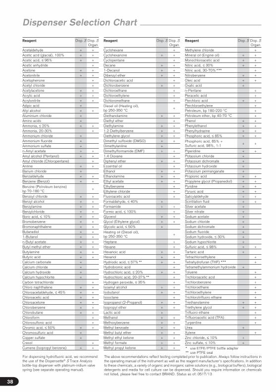
Dispenser Selection Chart
Reagent Disp. S Disp. S Organ
Acetaldehyde + +Acetic acid (glacial), 100% + +Acetic acid, ≤ 96% + +Acetic anhydride +Acetone + +Acetonitrile + +Acetophenone +Acetyl chloride +Acetylacetone + +Acrylic acid + +Acrylonitrile + +Adipic acid +Allyl alcohol + +Aluminium chloride +Amino acids +Ammonia, ≤ 20% + +Ammonia, 20-30% +Ammonium chloride +Ammonium fluoride +Ammonium sulfate +n-Amyl acetate + +Amyl alcohol (Pentanol) + +Amyl chloride (Chloropentane) +Aniline + +Barium chloride +Benzaldehyde + +Benzene (Benzol) + +
Benzine (Petroleum benzine) bp 70-180 °C
+
Benzoyl chloride + +Benzyl alcohol + +Benzylamine + +Benzylchloride + +Boric acid, ≤ 10% + +Bromobenzene + +Bromonaphthalene + +Butanediol + +1-Butanol + +n-Butyl acetate + +Butyl methyl ether + +Butylamine + +Butyric acid + +Calcium carbonate +Calcium chloride +Calcium hydroxide +Calcium hypochlorite +Carbon tetrachloride +Chloro naphthalene + +Chloroacetaldehyde, ≤ 45% + +Chloroacetic acid + +Chloroacetone + +Chlorobenzene + +Chlorobutane + +Chloroform +Chlorosulfonic acid +Chromic acid, ≤ 50% + +Chromosulfuric acid +Copper sulfate +Cresol +Cumene (Isopropyl benzene) + +
Reagent Disp. S Disp. S Organ
Cyclohexane +Cyclohexanone + +Cyclopentane +Decane + +1-Decanol + +Dibenzyl ether + +Dichloroacetic acid +Dichlorobenzene + +Dichloroethane +Dichloroethylene +Dichloromethane +
Diesel oil (Heating oil), bp 250-350 °C
+
Diethanolamine + +Diethyl ether +Diethylamine + +1.2 Diethylbenzene + +Diethylene glycol + +Dimethyl sulfoxide (DMSO) + +Dimethylaniline +Dimethylformamide (DMF) + +1.4 Dioxane +Diphenyl ether + +Essential oil +Ethanol + +Ethanolamine + +Ethyl acetate + +Ethylbenzene +Ethylene chloride +Fluoroacetic acid +Formaldehyde, ≤ 40% +Formamide + +Formic acid, ≤ 100% +Glycerol + +Glycol (Ethylene glycol) + +Glycolic acid, ≤ 50% +
Heating oil (Diesel oil), bp 250-350 °C
+
Heptane +Hexane +Hexanoic acid + +Hexanol + +Hydriodic acid, ≤ 57% ** + +Hydrobromic acid +Hydrochloric acid, ≤ 20% + +Hydrochloric acid, 20-37% ** +Hydrogen peroxide, ≤ 35% +Isoamyl alcohol + +Isobutanol + +Isooctane +Isopropanol (2-Propanol) + +Isopropyl ether + +Lactic acid +Methanol + +Methoxybenzene + +Methyl benzoate + +Methyl butyl ether + +Methyl ethyl ketone + +Methyl formate + +Methyl propyl ketone + +
Reagent Disp. S Disp. S Organ
Methylene chloride +Mineral oil (Engine oil) + +Monochloroacetic acid + +Nitric acid, ≤ 30% + +Nitric acid, 30-70% */** +Nitrobenzene + +Oleic acid + +Oxalic acid +n-Pentane +Peracetic acid +Perchloric acid + +Perchloroethylene +Petroleum, bp 180-220 °C +Petroleum ether, bp 40-70 °C +Phenol + +Phenylethanol + +Phenylhydrazine + +Phosphoric acid, ≤ 85% + +
Phosphoric acid, 85% + Sulfuric acid, 98%, 1:1
+ +
Piperidine + +Potassium chloride +Potassium dichromate +Potassium hydroxide +Potassium permanganate +Propionic acid + +Propylene glycol (Propanediol) + +Pyridine + +Pyruvic acid + +Salicylaldehyde + +Scintilation fluid + +Silver acetate +Silver nitrate +Sodium acetate +Sodium chloride +Sodium dichromate +Sodium fluoride +Sodium hydroxide, ≤ 30% +Sodium hypochlorite +Sulfuric acid, ≤ 98% + +Tartaric acid +Tetrachloroethylene +Tetrahydrofuran (THF) */** +Tetramethylammonium hydroxide +Toluene +Trichloroacetic acid +Trichlorobenzene +Trichloroethane +Trichloroethylene +Trichlorotrifluoro ethane +Triethanolamine + +Triethylene glycol + +Trifluoro ethane +Trifluoroacetic acid (TFA) +Turpentine +Urea +Xylene +Zinc chloride, ≤ 10% +Zinc sulfate, ≤ 10% +
* use ETFE/PTFE bottle adapter ** use PTFE seal
For dispensing hydrofluoric acid, we recommend the use of the Dispensette® S Trace Analysis bottle-top dispenser with platinum-iridium valve spring (see separate operating manual).
The above recommendations reflect testing completed prior to publication. Always follow instructions in the operating manual of the instrument as well as the reagent manufacturer‘s specifications. In addition to these chemicals, a variety of organic and inorganic saline solutions (e.g., biological buffers), biological detergents and media for cell culture can be dispensed. Should you require information on chemicals not listed, please feel free to contact BRAND. Status as of: 0517/13

Eng
lish
Operating Elements
Recirculation tube
Telescoping filling tube
Volume adjustment
Mounting toolFilling and recirculation tube
Locking
39
Cover plate
Volume adjustment
Housing
Screw cap
valve lever
Protective sleeve/ Dispensing cylinder
Piston Piston
Valve block (GL 45 bottle thread)
Discharge tube
Recirculation
Piston seat
Pointer
Knob
Safety lock
Cover plate
Piston mounting nut
Locking
Dis
pens
ette
® S
Dig
ital
Dis
pens
ette
® S
A
nalo
g-ad
just
able

1
2
40
First Steps
Is everything in the package?
Confirm that your package includes:Bottle-top dispenser Dispensette® S or Dispensette® S Organic, discharge tube or discharge tube with recirculation valve, telescoping filling tube, recirculation tube (included only in recirculation valve models), mounting tool, bottle adapters (listed below), a performance certificate and this operating manual.
Wear protective clothing, eye protection and gloves! Follow all safety instructions and observe limitations of use and operating limitations (page 34-36).
Warning:
Assembly
Nominal volume, ml Adapters for bottle thread
Filling tubeLength, mm
1, 2, 5, 10 GL 24-25, GL 28/S 28, GL 32-33, GL 38, S 40 125-240
25, 50, 100 GL 32-33, GL 38, S 40 170-330
2. Mounting the instrument on a bottle and align-ment
Screw the instrument (GL 45 threads) onto the reagent bottle, and then align the discharge tube with the bottle label. This is done by rotating the valve block with the discharge tube (Fig. 2).
To avoid tipping over, use a bottle stand for small bottles.
1. Mounting the filling tube/ recir-culation tube
Adjust the length of the telescoping fill-ing tube to the bottle height and attach it. Center and attach the filling tube (part with smaller diameter) carefully to avoid damaging the nozzle. If a discharge tube with a recirculation valve is used, the optional recirculation tube must also be installed. Insert it with the opening point-ing outward (Fig. 1).

3
Eng
lish
41
First Steps
Note:
Warning:
For bottles with other thread sizes, select a suitable adapter.
The adapters supplied with the instrument are made of polypropylene (PP), and can only be used for media which do not attack PP.Alternatively ETFE/PTFE bottle adapters can be used (‚Accessories‘, page 56). The suitabillity of ETFE/PTFE bottle adapters must be checked by the user.
Always wear protective gloves when touching the instrument or the bottle, especially when using dangerous liquids.When mounted to a reagent bottle, always carry the instrument as shown in figure 3!
Assembly (continued)

2
3
4
5
30 mm
1
!
42
Priming
Note:
1. Open the screw cap of the discharge tube (see 'instrument with recirculation valve', Fig. 1). To avoid splashes, hold discharge tube orifice on the inner wall of a suitable receiving vessel.
2. For priming pull up the piston approx. 30 mm and push it down rapidly until the lower stop. Repeat this procedure approximately 3 times until the discharge tube is bubble-free (Fig. 3).
1. Open the screw cap of the dispensing tube (Fig. 1).
2. Set valve to 'Recirculate' (Fig. 2).
3. For priming gently pull up the piston approx. 30 mm and push it down rapidly until the lower stop. Repeat this process at least 5 times (Fig. 3).
4. Turn valve to 'Dispense' (Fig. 4).
5. To avoid splashes when priming hold the discharge tube on the inner wall of a suitable receiving vessel and dispense liquid to prime the discharge tube until it is bubble-free. Wipe away any remaining drops from the discharge tube (Fig. 5).
Before using the instrument for the first time, ensure it is rinsed carefully and discard the first few samples dispensed. Avoid splashes.
Wear protective clothing, eye protection and gloves! Never press down the piston when the screw cap is screwed on! Avoid splash-ing the reagent! Liquid may accumulate in the screw cap. To avoid splashes dispense slowly. Follow all safety instructions and observe limitations of use and operating limitations (page 34-35).
Warning:
Instruments with recirculation valve
Instruments without recirculation valve

!
–+
1
2
3
21 3 Eng
lish
43
Dispensing
Digital: Rotate the volume-setting wheel until the desired volume is indicated (mechanical counter).
Fixed-volume: The volume is non-adjustable and cannot be changed.
1. Setting the volume
2. Dispensing
After using the piston, always press it down to the lower stop (parking position).
Caution:
Warning!
Analog-adjustable: Loosen the volume selector thumb screw ¾ turn (1), set the pointer to the desired volume (2) and then retighten the volume thumb screw (3).
a) Remove screw cap from the discharge tube (Fig. 1).
b) When using instruments equipped with the recirculation valve, turn the valve to 'Dispensing'.
c) Hold the discharge tube orifice on the inner wall of a suitable receiving vessel.
d) Gently lift the piston until the upper stop and then depress piston slowly and steadily with minimal force until the lower stop (Fig. 2).
e) Wipe off the discharge tube against the inner wall of the receiving vessel.
f) Reattach screw cap to discharge tube (Fig. 3).
Wear protective clothing, eye protection and gloves! Never press down the piston when the screw cap is screwed on! Avoid splash-ing the reagent! Liquid may accumulate in the screw cap. To avoid splashes dispense slowly. Follow all safety instructions and observe limitations of use and operating limitations (page 34-35).

2
3
1
4
44
Accessories
Warning:
For serial dispensing the flexible discharge tube can be used for the bottle-top dispenser Dispensette® S and Dispensette® S Organic ('Accessories', page 57). The specified accuracy and coefficient of variation of the instrument are only obtained for volumes > 2 ml and by gently approaching the upper and lower stops. The coil of the tubing can be stretched to a length of the 800 mm max. The entire coil must lie in regular loops and must not be twisted.
The applicable operating exclusions are those for the corresponding instrument used.
Assembly
1. If the Dispensette® S was in use, the instrument must be cleaned before mounting the flexible discharge tube (see page 49).
2. Instruments with a recirculating valve should be set to 'Recircu-late', and the valve lever pulled upwards to remove it.
3. Slide the discharge tube housing all the way up, then pull it forward with gentle up and down motions (Fig. 1).
4. Push the flexible discharge tube holder from the bottom of the valve block (Fig. 2) and tighten it. For this, Dispensette® S must not be mounted on the bottle. Install the receiver tube.
5. Press the plug of the recirculation valve downwards.
6. Slide the flexible discharge tube housing into the valve block up to the stop (Fig. 3).
7. Slide the discharge tube housing all the way down (Fig. 4).
8. Attach the valve handle that fits the discharge valve and press it in firmly. Note the color coding and marking (see mounting instruction 'Flexible discharge tube for Dispensette® S').
There should be no visible damage to the discharge tube (e.g. kinks or the like). Each time you are going to use the tubing, examine it carefully! To dispense aggressive liquids, you should take safety measures in addition to the normal precautions. We recommend use of a protective shield. The bottle must be supported using a bottle stand. To help avoid reagent splashing from the tube, always grip the tube firmly by the handle and replace into the holder after use. For cleaning rinse the tube carefully. Do not dismantle!
The following optional accessories are available:
Use a bottle stand ('Accessories', page 58).
Note:
Flexible discharge tube with recirculation valve

1
2
3
1
2
Eng
lish
45
Accessories
Use of a drying tube, filled with a suitable absorbent (purchased separately), might be necessary for moisture- and CO2- sensitive media ('Accessories', page 58).
Assembly
1. Use a coin to unscrew the air vent cap (Fig. 1).
2. Screw the filled drying tube in (Fig. 2).
3. Place the PTFE sealing ring on the bottle thread (Fig. 3) and screw the instrument onto the bottle.
If necessary, seal the threads of the drying tube, the bottle and/or the bottle adapter with PTFE tape.
Note:
For sterile media we recommend the air vent cap with Luer-cone to attach a micro filter. This provides increased protection against con-tamination by displacement air (see 'Accessories', page 58).
Assembly
1. Unscrew the air vent cap (see 'Assembly Drying tube', Fig. 1).
2. Screw in the air vent cap with a Luer cone (Fig. 1).
3. Place the PTFE sealing ring on the bottle thread and screw the instrument onto the bottle.
4. Insert a commercially available sterile filter into the Luer cone (Fig. 2).
For highly volatile media we recommend to seal the connection from valve bloc to bottle with the PTFE sealing ring and PTFE tape (see 'Accessories', page 58).
Assembly
Place the PTFE sealing ring on the bottle thread or the screwed-on adapter (Fig. 3) and screw the instrument onto the bottle.
Drying tube
Sealing ring for valve block
Air vent cap for micro filter with Luer-cone

!20 °C
Ex
Error Limits
Error limits related to the nominal capacity (= maximum volume) indicated on the instrument, obtained when instrument and distilled water are equilibrated at ambient temperature (20 °C/68 °F). Testing takes place according DIN EN ISO 8655-6 with a completely filled instrument and with uniform and smooth dispensing.
46
Error limits
Nominal volume ml
A* ≤ ± % µl
CV* ≤ % µl
1 0.6 6 0.2 2
2 0.5 10 0.1 2
5 0.5 25 0.1 5
10 0.5 50 0.1 10
25 0.5 125 0.1 25
50 0.5 250 0.1 50
100 0.5 500 0.1 100
Partial volume
The percentage values for A and CV are relative to the nominal volume (VN) and must be converted for partial volumes (Vp).
The error limits in DIN EN ISO 8655-5 are satisfied with a significant margin. The maximum error for a single measurement is calculated from the sum of error limits EL = A + 2 × CV (e.g., for the 25 ml size: 125 µl + 2 x 25 µl = 175 µl).
VN
VT
AT = · AN
e.g. Volume A* ≤ ± % µl
CV* ≤ % µl
VN 25.0 0.5 125 0.1 25
VT = 50% N 12.5 1.0 125 0.2 25
VT = 10% N 2.5 5.0 125 1.0 25
* A = Accuracy, CV = Coefficient of Variation
Note:
Type Digital • Easy Calibration is manufac-tured under U.S. Patent 5,957,330.

Eng
lish
47
xi = results of weighingsn = number of weighings
Z = correction factor (e. g., 1.0029 µl/mg at 20 °C, 1013 hPa)
V0 = nominal volume
Mean volume
V – V0
V0
A% = · 100Σ (xi – x ) 2
n – 1s = Z ·
Mean value x =Σ xi
n Mean volume V = x · Z
Accuracy Standard deviation Coefficient of variation
Checking the Volume (Calibration)
100 s
VCV% =
Gravimetric volume testing according to DIN EN ISO 8655-6 (for measurement conditions, see 'Error Limits', page 46) is performed as follows:
1. Preparation of the instrument
Clean the instrument ('Cleaning', page 49-52), fill it with distilled H2O and then prime it carefully.
2. Check the volume
a) 10 dispensing operations with distilled H2O in 3 Volume ranges (100 %, 50 %, 10 %) are recommended.
b) For filling pull up the piston gently until the upper stop of the volume set.
c) For discharge depress piston slowly and steadily without force until the lower stop.
d) Wipe off the tip of discharge tube.
e) Weigh the dispensed quantity on an analytical balance. (Please follow the operating manual of the balance manufacturer.)
f) Calculate the dispensed volume. The Z factor takes account of the temperature and air buoyancy.
3. Calculations
Depending on use, we recommend that gravimetric testing of the instrument be carried out every 3-12 months. This time frame should be adjusted to correspond with individual requirements. The complete testing procedure (SOP) can be downloaded at www.brand.de. In addition, you can also perform a func-tion test at shorter intervals, e.g. dispensing the nominal volume into a volumetric test flask (volumetric flask with 3 marks, DAkkS calibrated). For GLP- and ISO-compliant evaluations and documentation, we recommend the EASYCAL™ calibration software from BRAND. A demo version can be downloaded from www.brand.de.
21
3 4
2
3
1
4
5 6
Adjustment
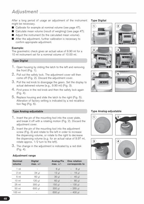
After a long period of usage an adjustment of the instrument might be necessary.� Calibrate for example at nominal volume (see page 47).� Calculate mean volume (result of weighing) (see page 47).� Adjust the instrument (to the calculated mean volume).� After the adjustment, further calibration is necessary to
confirm appropiate adjustment.
Example: The gravimetric check gives an actual value of 9.90 ml for a 10 ml instrument set for a nominal volume of 10.00 ml.
48
1. Open housing by sliding the latch to the left and removing the front (Fig. 1).
2. Pull out the safety lock. The adjustment cover will then come off (Fig. 2). Discard the adjustment cover.
3. Pull the red knob to disengage the gears. Set the display to actual delivered volume (e.g., 9.90 ml) (Fig. 3).
4. First press in the red knob and then the safety lock again (Fig. 4).
5. Replace housing and slide the latch to the right (Fig. 5). Alteration of factory setting is indicated by a red recalibra-tion flag (Fig. 6).
1. Insert the pin of the mounting tool into the cover plate, and break it off with a rotating motion (Fig. 2). Discard the adjustment cover.
2. Insert the pin of the mounting tool into the adjustment screw (Fig. 3) and rotate to the left in order to increase the dispensing volume, or rotate to the right to decrease the dispensing volume (e.g. for an actual value of 9.97 ml, rotate approx. 1/2 turn to the left).
3. The change in the adjustment is indicated by a red disk (Fig. 4).
Nominal volume
Digital max. +/-
Analog/Fix max. +/-
One rotation corresponds to
1 ml - 6 µl ~ 8 µl
2 ml 24 µl 12 µl ~ 16 µl
5 ml 60 µl 30 µl ~ 40 µl
10 ml 120 µl 60 µl ~ 80 µl
25 ml 300 µl 150 µl ~ 130 µl
50 ml 600 µl 300 µl ~ 265 µl
100 ml - 600 µl ~ 400 µl
Type Analog-adjustable
Type Digital
Adjustment range
Type Digital
Type Analog-adjustable

1
2a
Eng
lish
49
Cleaning
Cleaning
The cylinder, valves, telescoping filling tube and discharge tube contain reagent! Never remove the discharge tube while the dispensing cylinder is filled. Point the valves and tube openings away from your body. Wear protective clothing, eye protection and appropriate hand protection.
Warning!
� immediately when the piston is difficult to move
� before changing the reagent
� prior to long term storage
� prior to dismantling the instrument
� prior to autoclaving
The instrument must be cleaned in the following situations to assure correct operation:
� prior to changing the valve
� regularly when using liquids which form deposits (e.g., crystallizing liquids)
� regularly when liquids accumulate in the screw cap
Note:
The pistons and cylinders are individually matched, and should not be interchanged with piston from other instruments!
1. Screw the instrument onto an empty bottle and empty it com-pletely by dispensing (Fig. 1).If the instrument is equipped with a recirculation valve, it must be emptied in both the 'dispense' and 'recirculate' settings.
2. Screw the instrument onto a bottle filled with a suitable cleaning agent (e.g. deionized water) and rinse the instrument several times by completely filling and emptying it.
3. Disassembly of the piston:
For proper cleaning and removal of any deposits in the parts through which liquids pass, also always completely with draw the piston from the cylinder after rinsing with a suitable cleaning solution. If neces-sary, the parts can also be cleaned in an ultrasonic bath.
a) Analog-adjusted and fixed-volume model
Hold the housing securely and unscrew the piston seat completely by turning it to the left. Carefully pull out the piston (Fig. 2a).

2b
3
Cleaning
Move the latch to the left and remove the front housing.
Right! Wrong!
50
b) Digital type
3. Disassembly of the piston (continued).
Note:
Place the tip of the mounting tool in the piston mounting nut, and turn the mounting tool coun-ter-clockwise to loosen the piston mount. Then carefully pull out the piston of the cylinder.
4. Clean piston and cylinder (Fig. 3). If necessary carefully remove deposits at the edge of the glass cylinder.
5. Rinse the piston and cylinder with deionized water, and dry them carefully.
6. Insert the piston completely into the cylinder and then reassemble the instrument. The piston can only be inserted into the cylinder when the discharge tube is mounted.
Carry out assembly and dismantling at the maximum volume setting only (Fig. 2b).
Digital type
The stop segment must engage underneath the cylinder’s stop ring.When tightening the piston mounting nut using the mounting tool, use your thumbs to press the piston/cylinder unit back towards the back side of the housing.
For the Dispensette® S Organic, slide the piston into the cylinder vertically with a rotating motion.
Note:

3
2
1
2
1
Eng
lish
51
Replacement of discharge tube/ valves
Caution:
Always install the valve intended for the particular type and size of instrument! (see page 57 for 'ordering information')Identical filling valves are used in the Dispensette® S and Dispensette® S Organic, but the discharge valves are different. For easy identification, the discharge valves for the Dispensette® S Organic are labeled with "ORG" (Fig. 2)!
Replacing the discharge tube
1. Instruments with a recirculating valve should be set to 'Recirculate', and the valve lever pulled upwards to remove (Fig. 1).
2. Slide the discharge tube housing all the way up, then pull it forward with gentle up and down motions (Fig. 2).
3. Hold coupling piece of the new discharge tube and pull hous-ing up. Push housing into the valve block until it meets the stop.
4. Slide the discharge tube housing all the way down.
5. For instruments with a recirculation valve, pull up the valve lever to the 'Recirculate' position, and press it in tightly (Fig. 3).
Replacing valves
Discharge valve
1. After disassembling the discharge tube (see 'Replacing the discharge tube' above), use the mounting tool to unscrew the discharge valve (Fig. 1).
2. Screw in the new discharge valve first by hand, then tighten it securely with the mounting tool (the threads should no lon- ger be visible).
The discharge valve with a safety ball closes automatical-ly when the discharge tube is not mounted. Attaching the discharge tube opens the safety ball again.
Note:

1
2
52
Note:
If the instrument does not fill up, and if some elastic resistance is evident when the piston is pulled upward, then it is possible that the ball valve is stuck.In this case, loosen the ball valve using light pressure, for example, with a 200 µl plastic pipette tip (see the figure at the side).
Filling valve
1. Pull out the recirculation tube and the telescoping filling tube (Fig. 1).
2. Use the mounting tool to unscrew the filling valve (Fig. 2).
3. Screw in the new filling valve first by hand and then tighten it with the mounting tool.
Replacement of discharge tube/ valves
Replacing valves (cont.)

1a
1b
2
Eng
lish
53
Autoclaving
The instrument can be autoclaved at 121 °C (250 °F), 2 bar with a hold time of at least 15 minutes according to DIN EN 285.
Do not reassemble the instrument until it has cooled down to room temperature (Cooling time approx. 2 hours). After every autoclaving, inspect all parts for deformities or damage. If necessary, replace them.
It is the user's responsibility to ensure effective autoclaving.
Note:
1. The instrument must be carefully cleaned prior to autoclaving (see 'Cleaning', page 49-50).
2. Open the closure cap on the discharge tube, and for instruments with a recirculation valve, set the valve to 'Dispense'.
3. Check that the filling valve is securely seated (Fig. 1a). In the digital model, additionally check that the piston mounting is securely seated (Fig. 1b).
4. To ensure unhindered access for the steam and to prevent the ball valve in the filling valve from possibly becoming stuck, hold the instrument with the discharge piston pressed vertically down-ward, and gently tap against the casing with your hand (Fig. 2). Then lay it horizontally in the autoclave.
Be sure to avoid the instrument coming into contact with metal surfaces in the autoclave!
Preparation for autoclaving

54
Ordering Information
Dispensette® S, Analog-adjustable
Dispensette® S, Fixed-volume
Items supplied see page 40.
Note:
Dispensette® S, Digital
Capacity ml
Subdivision ml
Discharge tube without recirculation valveCat. No.
Discharge tube with recirculation valveCat. No.
0.1 - 1 0.005 4600 310 4600 311
0.2 - 2 0.01 4600 320 4600 321
0.5 - 5 0.02 4600 330 4600 331
1 - 10 0.05 4600 340 4600 341
2.5 - 25 0.1 4600 350 4600 351
5 - 50 0.2 4600 360 4600 361
Capacity ml
Subdivision ml
Discharge tube without recirculation valveCat. No.
Discharge tube with recirculation valveCat. No.
0.1 - 1 0.02 4600 100 4600 101
0.2 - 2 0.05 4600 120 4600 121
0.5 - 5 0.1 4600 130 4600 131
1 - 10 0.2 4600 140 4600 141
2.5 - 25 0.5 4600 150 4600 151
5 - 50 1.0 4600 160 4600 161
10 - 100 1.0 4600 170 4600 171
Capacity ml
Discharge tube without recirculation valveCat. No.
Discharge tube with recirculation valveCat. No.
1 4600 210 4600 211
2 4600 220 4600 221
5 4600 230 4600 231
10 4600 240 4600 241
Special fixed volumes: 0.5-100 ml (please state when ordering) 4600 290 4600 291

Eng
lish
55
Ordering Information
For dispensing hydrofluoric acid, we recommend the use of the Dispensette® S Trace Analysis bottle-top dispenser with platinum-iridium valve spring (see separate operating manual).
Note:
Dispensette® S Organic, Digital
Capacity ml
Subdivision ml
Discharge tube without recirculation valveCat. No.
Discharge tube with recirculation valveCat. No.
0.5 - 5 0.02 4630 330 4630 331
1 - 10 0.05 4630 340 4630 341
2.5 - 25 0.1 4630 350 4630 351
5 - 50 0.2 4630 360 4630 361
Dispensette® S Organic, Analog-adjustable
Capacity ml
Subdivision ml
Discharge tube without recirculation valveCat. No.
Discharge tube with recirculation valveCat. No.
0.5 - 5 0.1 4630 130 4630 131
1 - 10 0.2 4630 140 4630 141
2.5 - 25 0.5 4630 150 4630 151
5 - 50 1.0 4630 160 4630 161
10 - 100 1.0 4630 170 4630 171
Dispensette® S Organic, Fixed-volume
Capacity ml
Discharge tube without recirculation valveCat. No.
Discharge tube with recirculation valveCat. No.
5 4630 230 4630 231
10 4630 240 4630 241
Special fixed volumes: 2-100 ml (please state when ordering) 4630 290 4630 291

56
Bottle adapters
PP or ETFE/PTFE.
Discharge tube without recirculation valve
Pack of 1.
Description Nominal volume ml
Shape Length mm
Cat. No.
for Dispensette® S 1, 2, 5, 10 fine tip 108 7080 02
5, 10 standard 108 7080 05
25, 50, 100 fine tip 135 7080 06
25, 50, 100 standard 135 7080 08
for Dispensette® S Organic 5, 10 fine tip 108 7080 12
5, 10 standard 108 7080 14
25, 50, 100 fine tip 135 7080 16
25, 50, 100 standard 135 7080 19
Accessories · Spare Parts
Outerthread
for bottle thread/ ground joint
Material Cat. No.
GL 32 GL 25 PP 7043 25
GL 32 GL 28/ S 28 PP 7043 28
GL 32 GL 30 PP 7043 30
GL 32 GL 45 PP 7043 45
GL 45 GL 32 PP 7043 96
GL 45 GL 35 PP 7044 31
GL 45 GL 38 PP 7043 97
GL 45 S* 40 PP 7043 43
GL 45 S* 54 PP 7044 30
GL 45 S* 60 PP 7043 48
GL 32 GL 25 ETFE 7043 75
GL 32 GL 28/ S 28 ETFE 7043 78
GL 32 GL 45 ETFE 7043 95
GL 45 GL 32 ETFE 7043 98
GL 45 GL 38 ETFE 7043 99
GL 45 S* 40 PTFE 7043 91
GL 32 NS 19/26 PP 7044 19
GL 32 NS 24/29 PP 7044 24
GL 32 NS 29/32 PP 7044 29
* buttress thread

Eng
lish
57
Accessories · Spare Parts
Nominal volume ml
Discharge tubeOuter Ø Inner Ømm mm
Cat. No.
1, 2, 5, 10 3 2 7081 32
25, 50, 100 4,5 3 7081 34
* not suitable for hydrofluoric acid
for nominal volume ml
Cat. No.
1, 2* 6749
5, 10 6727
25, 50, 100 6728
* with valve marking '1 + 2'
Discharge tube with recirculation valve
Pack of 1.
Description Nominal volume ml
Shape Length mm
Cat. No.
for Dispensette® S 1, 2, 5, 10 fine tip 108 7081 02
5, 10 standard 108 7081 04
25, 50, 100 fine tip 135 7081 06
25, 50, 100 standard 135 7081 09
for Dispensette® S Organic 5, 10 fine tip 108 7081 12
5, 10 standard 108 7081 14
25, 50, 100 fine tip 135 7081 16
25, 50, 100 standard 135 7081 19
Flexible discharge tubing with recirculation valve*
for Dispensette® S and Dispensette® S Organic
PTFE, coiled, length 800 mm, with safety handle. Pack of 1.
Dispensette® S discharge valve
PFA/Boro 3.3/cera-mic/platinum-iridium.No valve marking.Pack of 1.
for nominal volume ml
Cat. No.
5, 10 6729
25, 50, 100 6730
Dispensette® S
Organic discharge valve
PFA/Boro 3.3/cera-mic/tantalum. Valve marked with 'ORG'.Pack of 1.
for nominal volume ml
Cat. No.
1, 2, 5, 10 6734
25, 50, 100 6735
Filling valve for Dispensette® S andDispensette® S Organic
Valve: PFA/ETFE/ Boro 3.3/ceramic.No valve marking.Pack of 1.
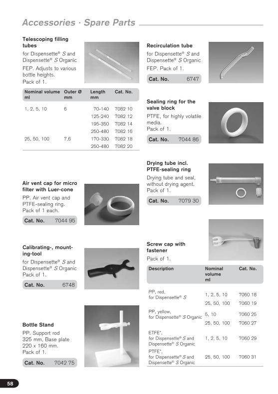
58
Accessories · Spare Parts
Calibrating-, mount-ing-tool
for Dispensette® S and Dispensette® S Organic Pack of 1.
Cat. No. 6748
Drying tube incl. PTFE-sealing ring
Drying tube and seal, without drying agent. Pack of 1.
Cat. No. 7079 30
Air vent cap for micro filter with Luer-cone
PP. Air vent cap and PTFE-sealing ring. Pack of 1 each.
Cat. No. 7044 95
Recirculation tube
for Dispensette® S and Dispensette® S Organic
FEP. Pack of 1.
Cat. No. 6747
Screw cap with fastener
Pack of 1.
Description Nominal volume ml
Cat. No.
PP, red, for Dispensette® S
1, 2, 5, 10 7060 18
25, 50, 100 7060 19
PP, yellow, for Dispensette® S Organic
5, 10 7060 25
25, 50, 100 7060 27
ETFE*, for Dispensette® S and Dispensette® S Organic
1, 2, 5, 10 7060 29
PTFE*, for Dispensette® S and Dispensette® S Organic
25, 50, 100 7060 31
Bottle Stand
PP. Support rod 325 mm, Base plate 220 x 160 mm. Pack of 1.
Cat. No. 7042 75
Cat. No. 7044 86
Sealing ring for the valve block
PTFE, for highly volatile media. Pack of 1.
Telescoping filling tubes
for Dispensette® S and Dispensette® S Organic
FEP. Adjusts to various bottle heights. Pack of 1.
Nominal volume ml
Outer Ø mm
Length mm
Cat. No.
1, 2, 5, 10 6 70-140 7082 10
125-240 7082 12
195-350 7082 14
250-480 7082 16
25, 50, 100 7,6 170-330 7082 18
250-480 7082 20

Eng
lish
59
Problem Possible cause Corrective action
Troubleshooting
Piston moves with difficulty or is stuck
Formation of crystals, dirty Stop dispensing immediately. Loosen piston with circular motion, but do not disassemble. Follow all cleaning instructions (page 49-52).
Filling not possible
Volume adjusted to minimum setting
Set to required volume (see page 43).
Filling valve stuck Unscrew the filling valve from the valve block, clean it, replace the filling valve if necessary. If the valve is stuck use a 200 µl pipette tip to loosen it (see page 52). If necessary replace the filling valve.
Dispensing not possible
Discharge valve stuck Unscrew the discharge valve from the valve block, clean it, replace the discharge valve if necessary (see page 51), use a 200 µl plastic tip to loosen any ball valve that is stuck.
Discharge tube or discharge tube with re-circulation valve cannot be mounted sufficiently
Discharge valve is not screwed in deeply enough
Tighten the discharge valve with the mounting tool until it meets the stop so that the threads are no longer visible.
Air bubbles in the instrument
Reagent with high vapor pressure has been drawn in too quickly
Slowly draw in reagent.
Valve screw connections loose Tighten the valves firmly with the mounting tool.
The instrument has not been primed
Prime the instrument (see page 42).
Filling tube is loose or damaged
Push the filling tube on firmly. If necessary cut off approx. 1 cm of tube at the upper end and re-connect it or replace filling tube.
Valves not firmly connected or damaged
Cleaning procedure (see page 49-52). Tighten the valves using the mounting tool.
Dispensed volume is too low
Filling tube is loose or damaged
Cleaning procedure (see page 49-52). Push the filling tube on firmly. If necessary, cut off approx. 1 cm of the tube at the upper end and re-connect it or replace filling tube (see page 51).
Filling valve is looseor damaged
Cleaning procedure (see page 49-52). Tighten the valves using the mounting tool. If necessary, replace filling valves.
Leaking liquid between instrument and bottle
Recirculation tube not connected
Connect recirculation tube (see page 38, Fig. 3).
Volatile reagent dispensed without sealing ring
Mount sealing ring (see page 45).

60
Repairs · contact addresses
– Clean and decontaminate the instrument carefully.
– It is essential always to include an exact description of the type of malfunc-tion and the media used. If information regarding media used is missing, the instrument cannot be repaired.
– Shipment is at the risk and the cost of the sender.
In the U.S. and Canada:
– Contact BrandTech Scientific, Inc. and obtain authorization for the return before sending your instrument for service.
– Return only cleaned and decontaminated instruments, with the Return Authorization Number prominently displayed on the outside of the package to the address provided with the Return Authorization Number.
BRAND GMBH + CO KGOtto-Schott-Straße 2597877 Wertheim (Germany)
Tel.: +49 9342 808-0Fax: +49 9342 808-98000E-Mail: [email protected]
USA and Canada:BrandTech® Scientific, Inc.11 Bokum RoadEssex, CT 06426-1506 (USA)
Tel.: +1-860-767 2562Fax: +1-860-767 2563www.brandtech.com
India:BRAND Scientific Equipment Pvt. Ltd. 303, 3rd Floor, ‘C‘ Wing, DelphiHiranandani Business Park, PowaiMumbai - 400 076 (India)
Tel.: +91 22 42957790 Fax: +91 22 42957791 E-Mail: [email protected] www.brand.co.in
China:BRAND (Shanghai) Trading Co., Ltd. Guangqi Culture Plaza Room 506, Building B No. 2899, Xietu Road Shanghai 200030 (P.R. China)
Tel.: +86 21 6422 2318Fax: +86 21 6422 2268 E-Mail: [email protected]
Contact addresses
Return for repair
Caution! Transporting of hazardous materials without a permit is a violation of federal law.
Outside the U.S. and Canada:
– Complete the “Declaration on Absence of Health Hazards” and send the instru-ment to the manufacturer or supplier. Ask your supplier or manufacturer for the form. The form can also be downloaded from www.brand.de.
Eng
lishISO 9001 and GLP-guidelines require regular examinations of your volumetric
instruments. We recommend checking the volume every 3-12 months. The interval depends on the specific requirements on the instrument. For instru-ments frequently used or in use with aggressive media, the interval should be shorter. The detailed testing instruction can be downloaded on www.brand.de or www.brandtech.com. BRAND also offers you the possibility to have your instruments calibrated by the BRAND Calibration Service or the BRAND-owned DAkkS Calibration Service. Just send in the instruments to be calibrated, accompanied by an indication of which kind of calibration you wish. Your instruments will be returned within a few days together with a test report (BRAND Calibration Service) or with a DAkkS Calibration Certificate. For further information, please contact your dealer or BRAND. Complete ordering information is available for download at www.brand.de (see Technical Documentation).
Calibration Service
61

Subject to technical modification without notice. Errors excepted.
Disposal
For the disposal of instruments, please observe the relevant national disposal regulations.
We shall not be liable for the consequences of improper handling, use, servic-ing, operation or unauthorized repairs of the instrument or the consequences of normal wear and tear especially of wearing parts such as pistons, seals, valves and the breakage of glass as well as the failure to follow the instructions of the operating manual. We are not liable for damage resulting from any actions not described in the operating manual or if non-original spare parts or components have been used.
U.S. and Canada:Information for warranty please see www.brandtech.com.
Warranty
62


9974 90 · Printed in Germany · 5/0817/7